Embed Size (px)
Citation preview
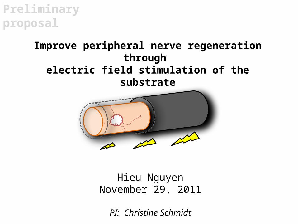
Improve peripheral nerve regeneration through electric field stimulation of the substrate
Hieu NguyenNovember 29, 2011
PI: Christine Schmidt
Preliminary proposal

2
Motivation
Motivation
• 11,000 Americans are affected by paralysis each year costing $7 billion
• An excess of 50,000 peripheral nerve repair procedures are performed annually
American Paralysis Association, 1997National Center for Health Statistics, Classification of Diseases, 9th Rev, 1995The Boston Globe. Afghanistan, September 2011. http://www.boston.com/bigpicture/2011/09/afghanistan_september_2011.htmlThe Animal Pet Doctor. http://animalpetdoctor.homestead.com/surg2.jpgDiabetic Foot Ulcer. Health.com 2009 http://www.health.com/health/static/hw/media/medical/hw/h9991432_001.jpg
3
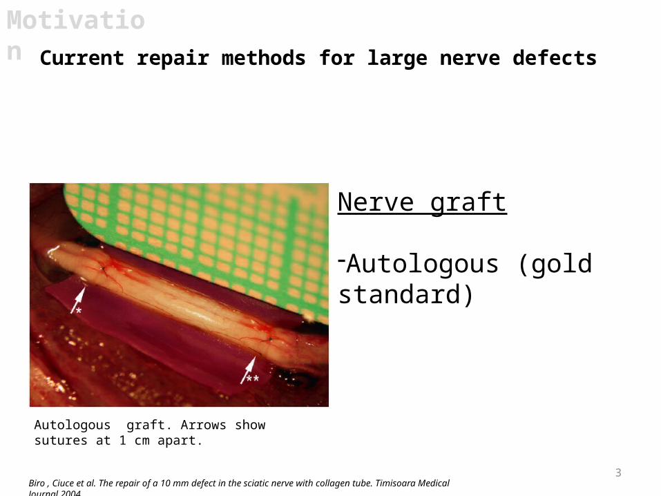
Current repair methods for large nerve defects
Motivation
Nerve graft
-Autologous (gold standard)
Biro , Ciuce et al. The repair of a 10 mm defect in the sciatic nerve with collagen tube. Timisoara Medical Journal 2004.
Autologous graft. Arrows show sutures at 1 cm apart.

4
Motivation
Avance® Nerve Graft. AxoGen® http://www.axogeninc.com/ . Published internet 2011.
Nerve graft
-Autologous (gold standard)-Acellular
Current repair methods for large nerve defects
Axogen’s acellular nerve graft.

5
Motivation
Biro , Ciuce et al. The repair of a 10 mm defect in the sciatic nerve with collagen tube. Timisoara Medical Journal 2004.
Nerve graft
-Autologous (gold standard)-Acellular-ECM/polymer-based
Current repair methods for large nerve defects
Collagen graft - arrows show sutures at 1 cm apart.
6
Motivation
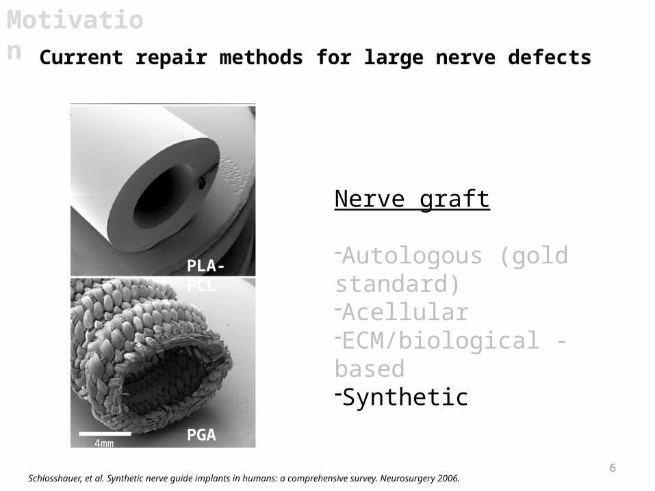
Schlosshauer, et al. Synthetic nerve guide implants in humans: a comprehensive survey. Neurosurgery 2006.
Nerve graft
-Autologous (gold standard)-Acellular-ECM/biological -based-Synthetic
Current repair methods for large nerve defects
PLA-PCL
PGA4mm
7
Motivation
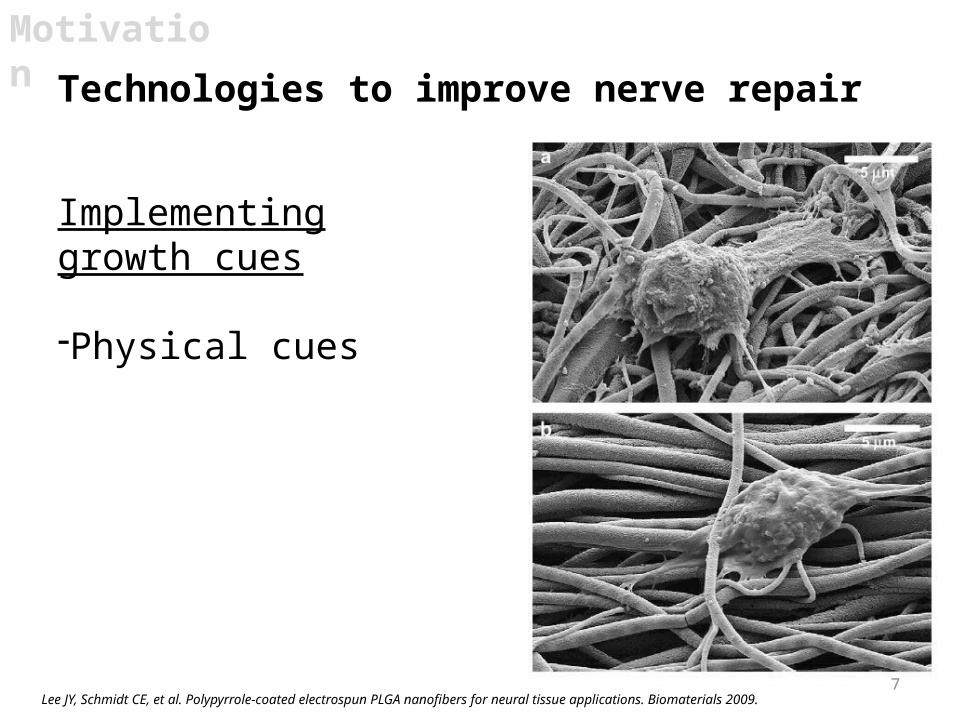
Implementing growth cues
-Physical cues
Lee JY, Schmidt CE, et al. Polypyrrole-coated electrospun PLGA nanofibers for neural tissue applications. Biomaterials 2009.
Technologies to improve nerve repair

8
Motivation
Li, Hoffman-Kim, et al. Multi-molecular gradients of permissive and inhibitory cues direct neurite outgrowth. Ann Biomed Eng 2008.
Implementing growth cues
-Physical cues-Chemical cues
Technologies to improve nerve repair
LN
CSPG
40µm

9
Motivation
Rajnicek, McCaig et al., Temporally and spatially… J. Cell Science 2006.
Implementing growth cues
-Physical cues-Chemical cues-Electrical cues
Technologies to improve nerve repair
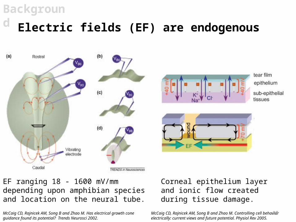
Electric fields (EF) are endogenous
EF ranging 18 - 1600 mV/mm depending upon amphibian species and location on the neural tube.
McCaig CD, Rajnicek AM, Song B and Zhao M. Has electrical growth cone guidance found its potential? Trends Neurosci 2002.
Corneal epithelium layer and ionic flow created during tissue damage.
McCaig CD, Rajnicek AM, Song B and Zhao M. Controlling cell behavior electrically: current views and future potential. Physiol Rev 2005.
Background
10
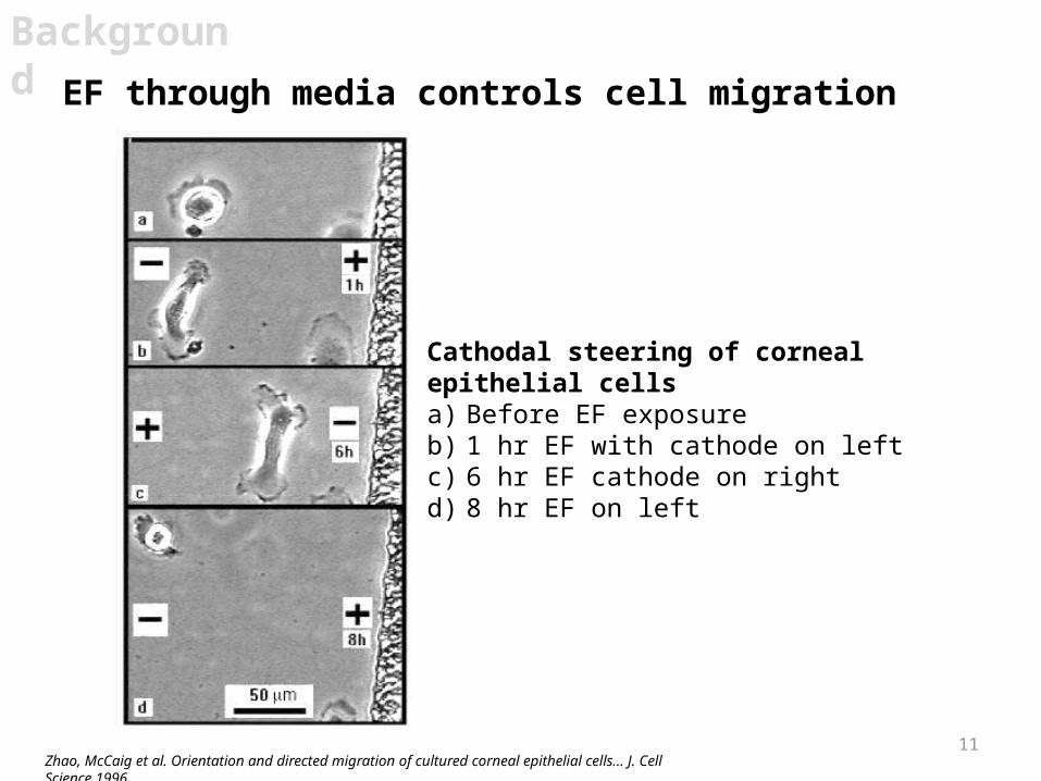
11Zhao, McCaig et al. Orientation and directed migration of cultured corneal epithelial cells… J. Cell Science 1996.
Background
EF through media controls cell migration
Cathodal steering of corneal epithelial cellsa) Before EF exposureb) 1 hr EF with cathode on leftc) 6 hr EF cathode on rightd) 8 hr EF on left
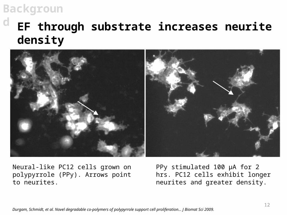
12Durgam, Schmidt, et al. Novel degradable co-polymers of polypyrrole support cell proliferation… J Biomat Sci 2009.
Background
EF through substrate increases neurite density
Neural-like PC12 cells grown on polypyrrole (PPy). Arrows point to neurites.
PPy stimulated 100 µA for 2 hrs. PC12 cells exhibit longer neurites and greater density.
13
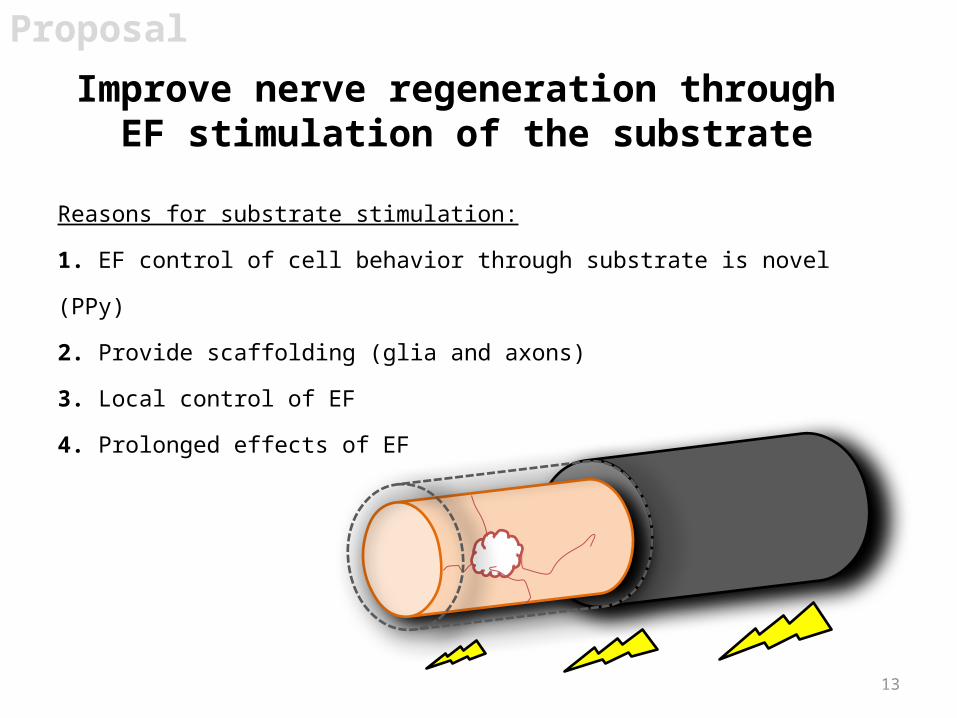
Improve nerve regeneration through EF stimulation of the substrate
Proposal
Reasons for substrate stimulation:
1. EF control of cell behavior through substrate is novel (PPy)
2. Provide scaffolding (glia and axons)
3. Local control of EF
4. Prolonged effects of EF

Aim 1 – Control cell growth by electrically stimulating a conductive substrate
Aims
Proposal
14
Aim 2 – Model and explore environmental changes surrounding cells within EFs
Aim 3 - Optimize an electrically conductive polymer to supply an EF across a nerve injury for commercial use
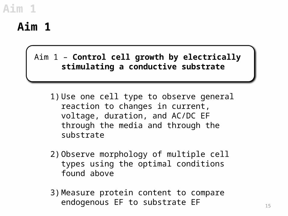
1) Use one cell type to observe general reaction to changes in current, voltage, duration, and AC/DC EF through the media and through the substrate
2) Observe morphology of multiple cell types using the optimal conditions found above
3) Measure protein content to compare endogenous EF to substrate EF
Aim 1
Aim 1
15
Aim 1 – Control cell growth by electrically stimulating a conductive substrate
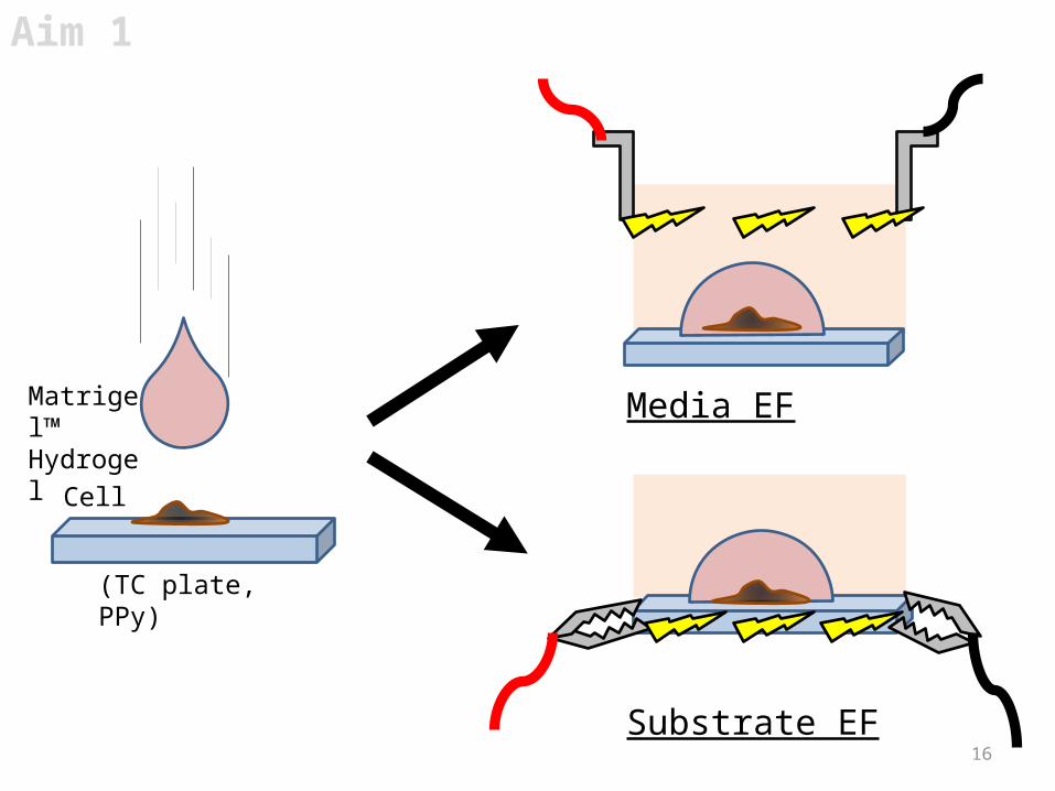
16Substrate EF
Media EFMatrigel™ Hydrogel
Cell
(TC plate, PPy)
Aim 1
17
Aim 1
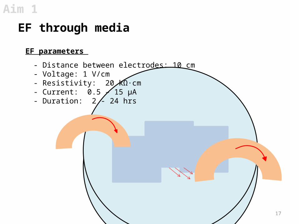
EF through media
EF parameters
- Distance between electrodes: 10 cm- Voltage: 1 V/cm - Resistivity: 20 kΩ·cm- Current: 0.5 – 15 µA- Duration: 2 - 24 hrs
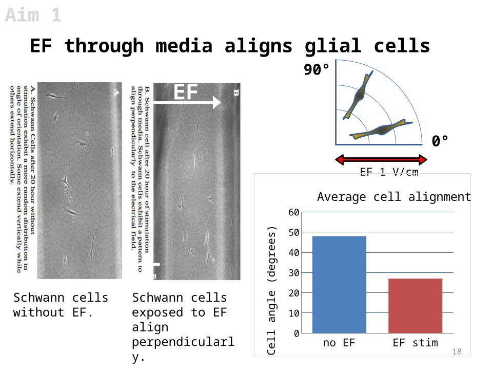
Schwann cells without EF.
Aim 1
EF through media aligns glial cells
18
90°
0°
EF 1 V/cm
no EF EF stim0
10
20
30
40
50
60
Average cell alignment
Cell
angl
e (d
egre
es)
EF
Schwann cells exposed to EF align perpendicularly.
100µm
19
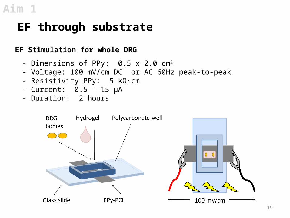
EF Stimulation for whole DRG
- Dimensions of PPy: 0.5 x 2.0 cm2
- Voltage: 100 mV/cm DC or AC 60Hz peak-to-peak- Resistivity PPy: 5 kΩ·cm- Current: 0.5 – 15 µA- Duration: 2 hours
Aim 1
EF through substrate

20
Aim 1
EF through substrate increases axon elongation
DRGs exposed to EF exhibit longer axons and growth parallel to EF (b III tubulin).
1mm
No EF
(axon length in µm) Control (n=506)
DC(n=358)
AC (n=281)
Average 820 927 (+13%) 996 (+21%)
Standard Deviation 302 278 343
Student’s t-test vs Control p<0.01 p<0.01
Axon lengths 3 days after 2 hr stimulation
21
Aim 1
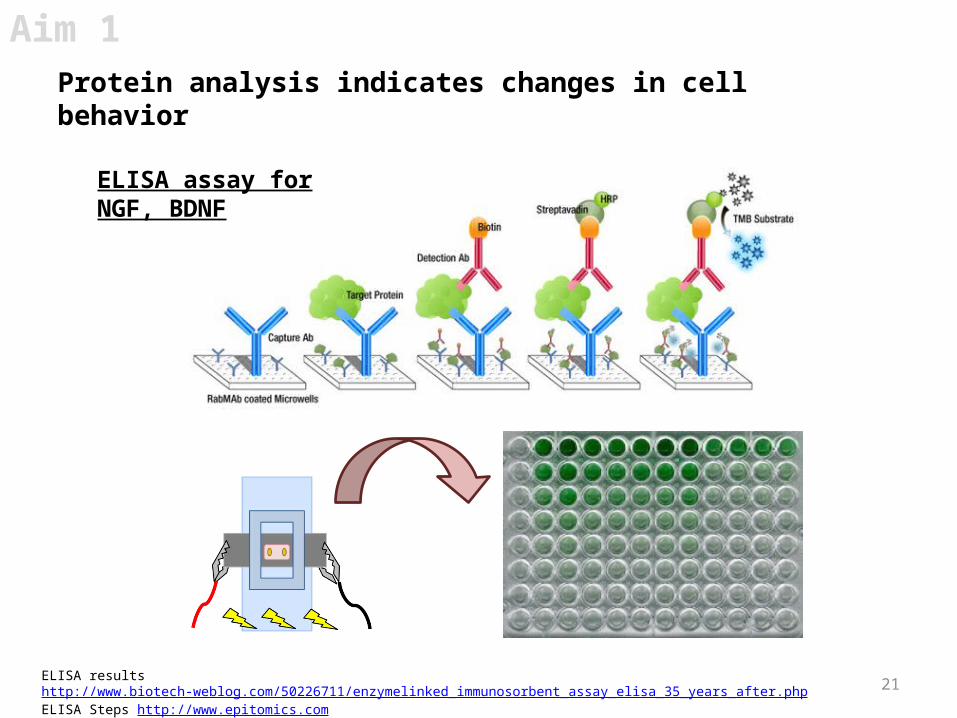
Protein analysis indicates changes in cell behavior
ELISA results http://www.biotech-weblog.com/50226711/enzymelinked_immunosorbent_assay_elisa_35_years_after.phpELISA Steps http://www.epitomics.com
ELISA assay for NGF, BDNF

22
Aim 1
Aim 1 – Future work
1) Determine whether I or V is changing cell behavior. Continue to observe cell changes in AC/DC EFs
2) Use optimized conditions above to observe changes in DRGs and astrocytes (possible bridge for CNS)
3) Supernatant is being collected for protein analysis of cells stimulated through the media vs substrate
Aim 1 – Control cell growth by electrically stimulating a conductive substrate
23
1) Model Debye length, induced current, and EF around a cell using Virtual Cell and COMSOL Multiphysics®
2) Can we create an electrical gradient inside a hydrogel
3) Examine cell behavior when placed on a stimulated hydrogel to see if there are any prolonged effects of EF to the environment
Aim 2
Aim 2
Aim 2 – Model and explore environmental changes surrounding cells within EFs
24
Aim 2
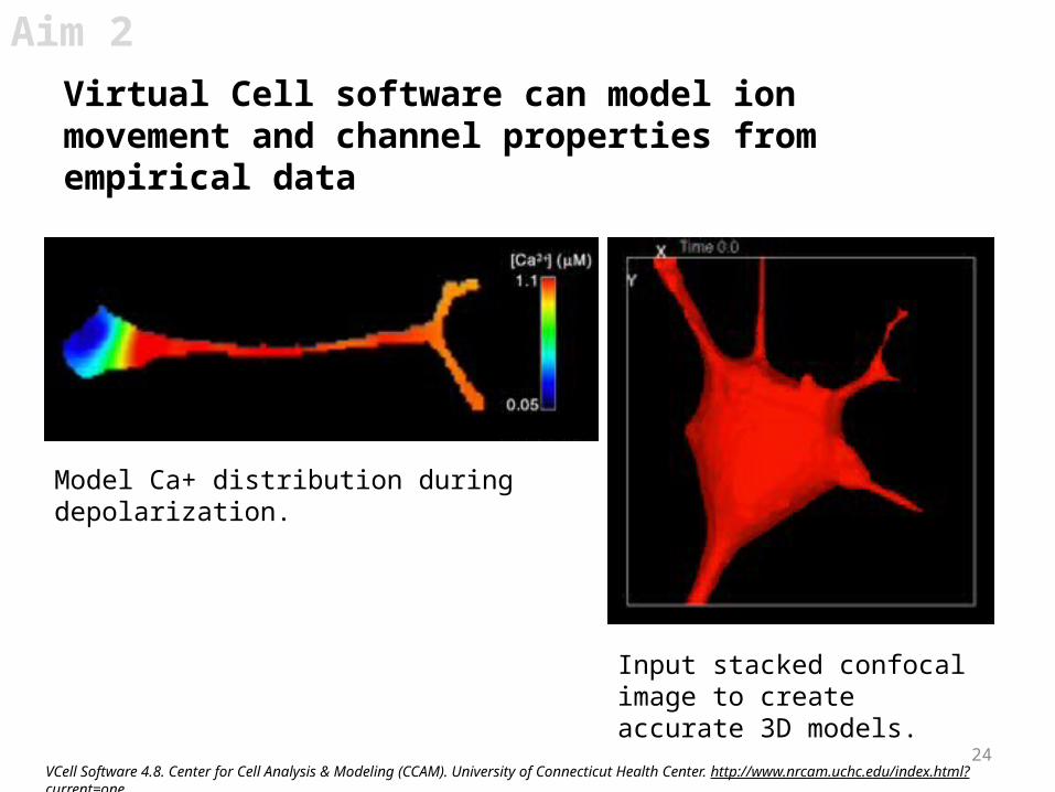
Virtual Cell software can model ion movement and channel properties from empirical data
VCell Software 4.8. Center for Cell Analysis & Modeling (CCAM). University of Connecticut Health Center. http://www.nrcam.uchc.edu/index.html?current=one.
Model Ca+ distribution during depolarization.
Input stacked confocal image to create accurate 3D models.
25
Aim 2
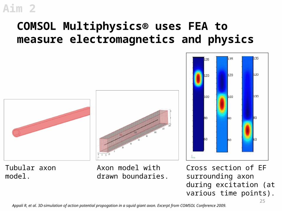
COMSOL Multiphysics® uses FEA to measure electromagnetics and physics
Appali R, et al. 3D-simulation of action potential propogation in a squid giant axon. Excerpt from COMSOL Conference 2009.
Tubular axon model. Axon model with drawn boundaries.
Cross section of EF surrounding axon during excitation (at various time points).

26
Aim 2
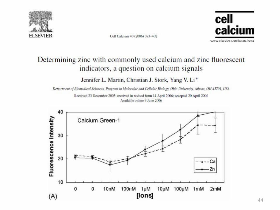
DC EF changes Ca+ concentration within a gel
Gel
Stimulate gel for 20 hrs Section gel into 5 parts
Add Calcium green-1
Calcium Green -1 http://www.umsl.edu/~tsytsarev/tsytsarev_files/Lecture10.htm
1 2
3 4
27
Aim 2
Control EF Stim0
10
20
30
40
50
60
Average cell alignment
Cell
angl
e (d
egre
es)90°
0°
EF 100 mV/cm
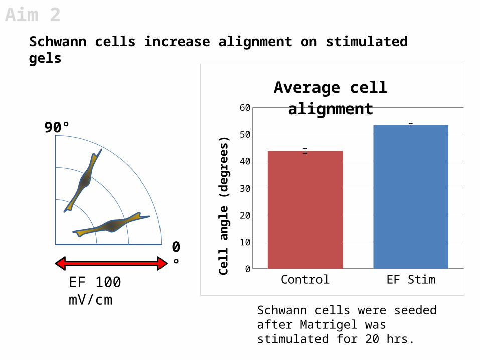
Schwann cells increase alignment on stimulated gels
Schwann cells were seeded after Matrigel was stimulated for 20 hrs.

28
1) Model Debye length, induced current, and EF arround a cell using Virtual Cell and COMSOL Multiphysics®
2) We have created and measured ionic changes in gels electrically stimulated through the substrate
3) Prolonged affects of stimulation on gel will need to be analyzed using microscopy/spectroscopy
Aim 2
Aim 2 – Future work
Aim 2 – Model and explore environmental changes surrounding cells within EFs

1) Test stability and biocompatibility of TDA’s polymer substrate
2) Examine cell behavior on 2D substrate exposed to EF (film)
3) Examine cell behavior in 3D structure exposed to EF (conduit)
Aim 3
Aim 3
29
Aim 3 – Optimize an electrically conductive polymer to supply an EF across a nerve injury for commercial use

30
Nerve
Aim 3

Glass slide
PPy-PCL
1.0 x 1.5 cm2 Polycarbonate wells
100 mV/cm
PC12 cells (20,000 cells)
Seed PC12
Pre-stim
Stim Image
2Timeline 2
1st day 2nd day 3rd day
Aim 3
Experimental setup for PPy stability and biocompatibility
31
32
NPS Control 1 2 PS Control 3 40
100
200
300
400
500
600
700
800
900
Total # of Live Cells on one PPy strip
Condition# Li
ve C
ells
24h
rs a
fter
stim
(w
/ st
.dev
.)
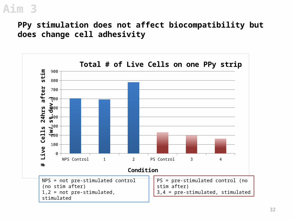
NPS = not pre-stimulated control (no stim after)1,2 = not pre-stimulated, stimulated
PS = pre-stimulated control (no stim after)3,4 = pre-stimulated, stimulated
Aim 3
PPy stimulation does not affect biocompatibility but does change cell adhesivity
33
Aim 3
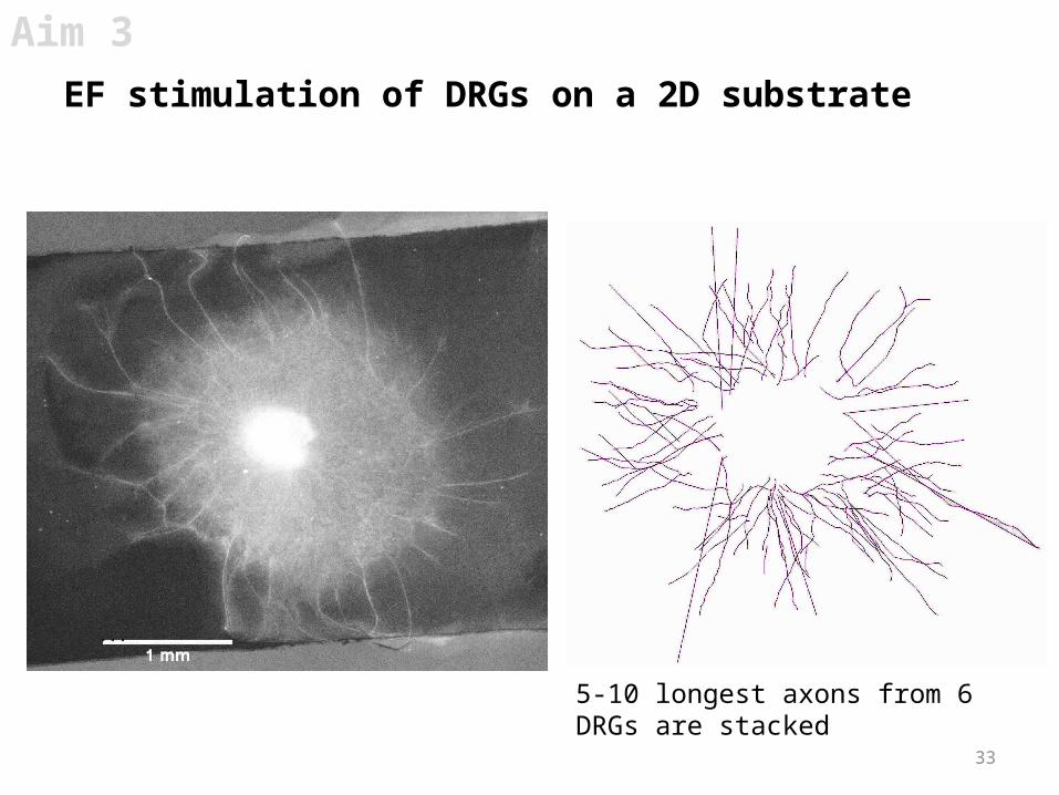
EF stimulation of DRGs on a 2D substrate
5-10 longest axons from 6 DRGs are stacked

34
Aim 3
EF stimulation of DRGs on a 2D substrate enhances axon growth toward electrodes
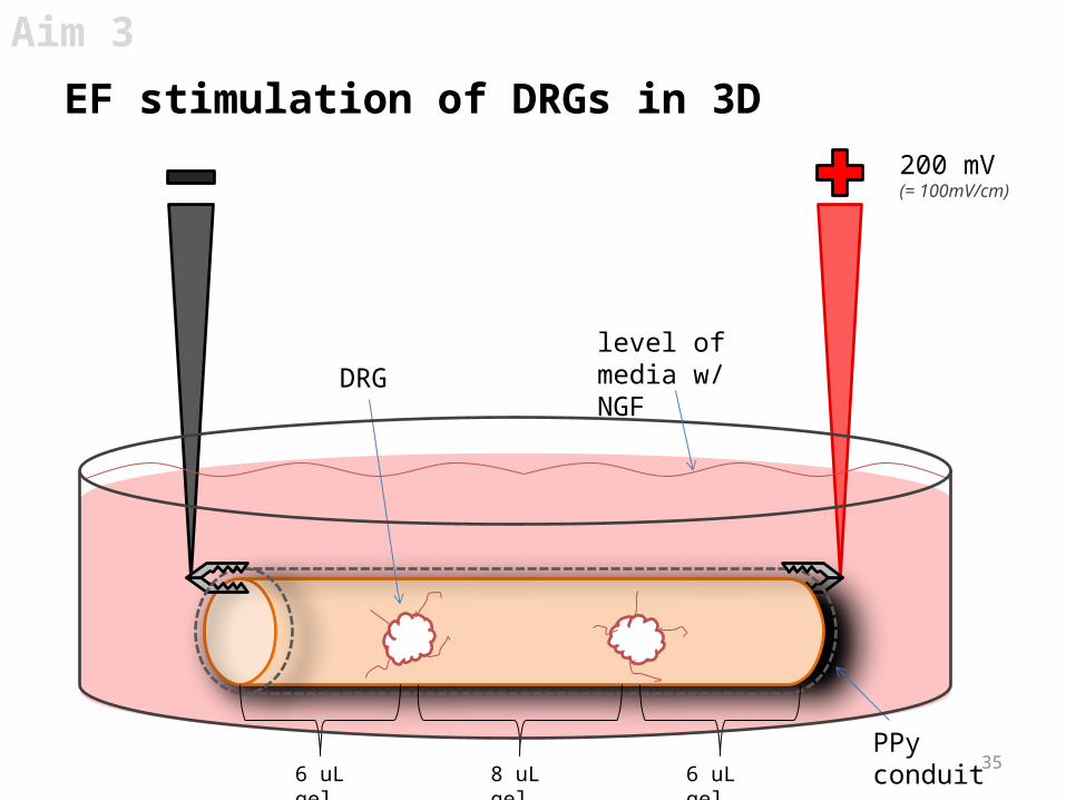
35PPy conduit
6 uL gel 8 uL gel 6 uL gel
DRGlevel of media w/ NGF
200 mV (= 100mV/cm)
Aim 3
EF stimulation of DRGs in 3D

36
Aim 3
EF stimulation of DRGs in 3D reduces axon density but may increase axon length
DRG in conduit with no EF DRG in conduit with EF 100 mV/cm for 2 hrs

37
1) TDA’s polymer is stable and biocompatible
2) DRGs stimulated with EF on 2D films display longer axons and directed growth towards electrodes
3) Need to repeat experiment to determine if EF stimulation in 3D conduits enhances nerve growth
Aim 3
Aim 3 – Future work
Aim 3 – Optimize an electrically conductive polymer to supply an EF across a nerve injury for commercial use
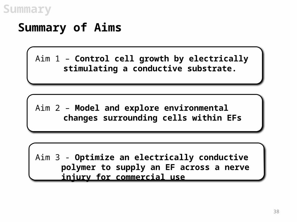
Aim 1 – Control cell growth by electrically stimulating a conductive substrate.
38
Aim 2 – Model and explore environmental changes surrounding cells within EFs
Aim 3 - Optimize an electrically conductive polymer to supply an EF across a nerve injury for commercial use
Summary
Summary of Aims
39
Aug
Sept
Oct
Nov
Dec
Jan
Feb
Mar
April
May
June
July
Aug
Sept
Oct
Nov
Dec
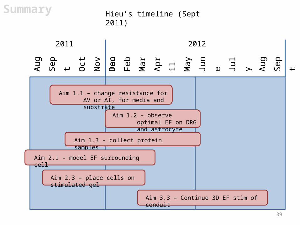
2011 2012
Aim 1.1 – change resistance for ΔV or ΔI, for media and substrate
Aim 1.3 – collect protein samples
Aim 2.1 – model EF surrounding cell
Aim 2.3 – place cells on stimulated gel
Aim 3.3 – Continue 3D EF stim of conduit
Hieu’s timeline (Sept 2011)Summary
Aim 1.2 – observe optimal EF on DRG and astrocyte
40
End
Acknowledgements
Schmidt groupChristine SchmidtJae Young LeeJon NickelsLeo ForcinitiZin KhaingJohn HardyCraig Milroy…and all other lab members!
My committeeRichard AldrichAaron BakerHenry RylanderLaura Suggs
Undergraduate AssistantsSung Ji AhnAlvin NguyenThomas MathewsDan WalkerJan NguyenJeff CoursenClaudia WeiJacque Chow
CollaborationsSilvia Luebben, TDAShawn Sapp, TDARobert Ross, VTI
FundingNDSEG FellowshipUndergraduate Research FellowshipIE Internship

41

42Schmidt, Langer,et al. Stimulation of neurite outgrowth using an electrically conducting polymer. Proc Natl Acad Sci 1997.
Background
EF through substrate increases neurite density
Neural-like PC12 cells increase neurite formationa) PC12 cells grown on polypyrrole (PPy) before stimulationb) PPy stimulated at 100 mV for 2 hrs, image taken 24 hrs after
43
Things to note
1. EF = electric field2. Current = movement of charged species3. Substrate = Polypyrrole (PPy)4. Cells used:
1. DRG = dorsal root ganglia2. Schwann cells3. Astrocytes
Proposal
44
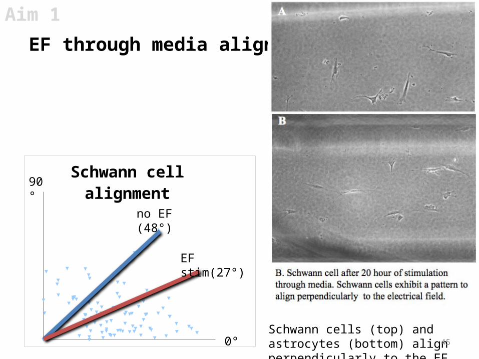
Schwann cells (top) and astrocytes (bottom) align perpendicularly to the EF.
EF
Aim 1
EF through media aligns glial cells
45
Schwann cell alignment
no EF (48°)
EF stim(27°)
90°
0°
46
Aim 1
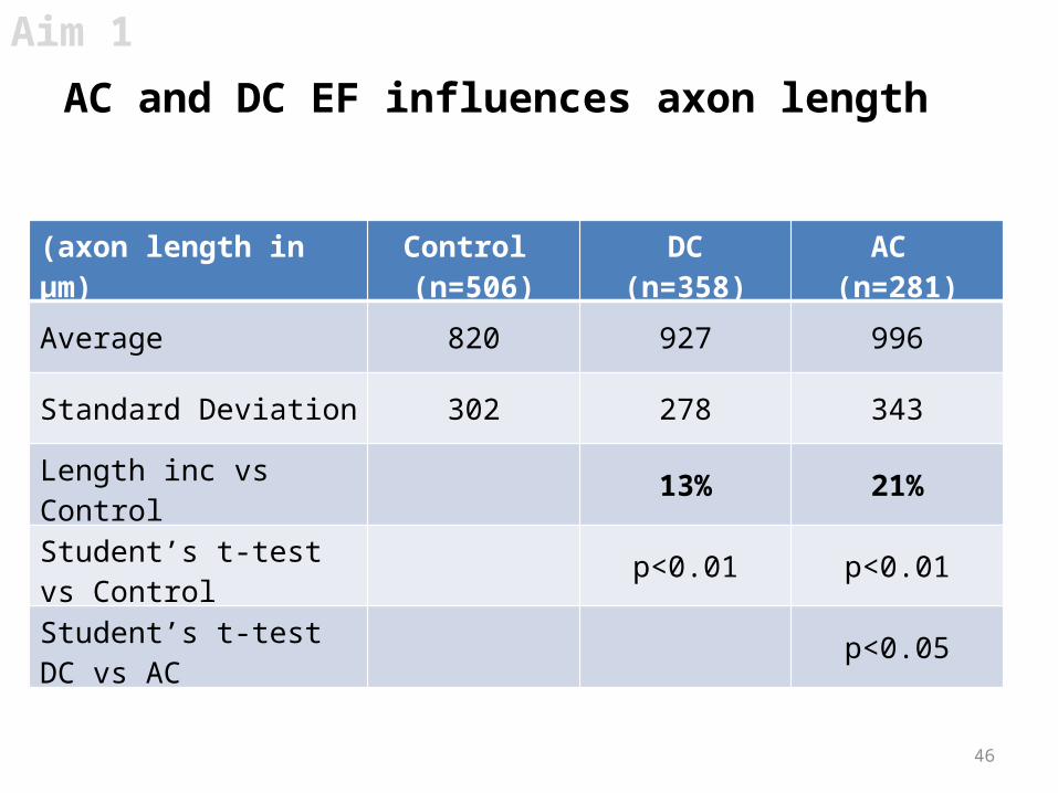
AC and DC EF influences axon length
(axon length in µm) Control (n=506)
DC(n=358)
AC (n=281)
Average 820 927 996
Standard Deviation 302 278 343
Length inc vs Control 13% 21%
Student’s t-test vs Control p<0.01 p<0.01
Student’s t-test DC vs AC p<0.05

47
Summary
Summary of Aims
Aim 1 - Determine how electrically stimulating a conductive substrate can control cell growth.(Characterization)
Aim 2 - Determine environmental changes around cells within EFs(Modeling and Exploratory)
Aim 3 - Optimize an electrically conductive polymer to supply an EF across a nerve injury(Translational)
![Insulin Receptor Substrate (IRS)-2 phosphorylation is ... · Insulin promotes the dephosphorylation of glycogen synthase (GS) and consequent stimulation of glycogen synthesis [10-12]](https://img.dokumen.tips/doc/110x75/5f0a00567e708231d4298871/insulin-receptor-substrate-irs-2-phosphorylation-is-insulin-promotes-the-dephosphorylation.jpg)


![[ABCS VIỆT NAM] 7-cau-hoi-giup-hieu-minh-hieu-tre](https://img.dokumen.tips/doc/110x75/559ae0a71a28ab052c8b47fb/abcs-viet-nam-7-cau-hoi-giup-hieu-minh-hieu-tre.jpg)


