Embed Size (px)
Citation preview


IMPORTANT SAFETY INSTRUCTIONSSave these instructions for later use.• Always use with the correct line voltage. Refer to the manufacturer's operating instructions for power requirements. Be advised that different operating
voltages may require the use of a different line cord and/or attachment plug.• Do not install the unit in an unventilated rack, or directly above heat producing equipment such as power amplifiers. Observe the maximum ambient
operating temperature listed in the product specification.• Slots and openings on the case are provided for ventilation – to ensure reliable operation and prevent it from overheating. These openings must not be
blocked or covered. Never push objects of any kind through any of the ventilation slots. Never spill a liquid of any kind on the unit.• Never attach audio power amplifier outputs directly to any of the unit's connectors.• To prevent shock or fire hazard, do not expose the unit to rain or moisture, or operate it where it will be exposed to water.• Do not attempt to operate the unit if it has been dropped, damaged, exposed to liquids, or if it exhibits a distinct change in performance indicating the need
for service.
This unit should only be opened by qualified service personnel. Removing covers will expose you to hazardous voltages.• Take precautions not to defeat the grounding or polarization of the unit's power cord.• Do not overload wall outlets, extension cords, or integral convenience receptacles, as this can result in a risk of fire or electrical shock.• Route power supply cords so that they are not likely to be walked on or pinched by items placed on or against them, paying
particular attention to cords at plugs, convenience receptacles, and the point at which they exit from the unit.• The unit should be cleaned only as recommended by the manufacturer.
This equipment has been tested and found to comply with the limits for a Class B digital device, pursuant to Part 15 of the FCC Rules. These limits are designedto provide reasonable protection against harmful interference in a residential installation. This equipment generates, uses and can radiate radio frequencyenergy and, if not installed and used in accordance with the instructions, may cause harmful interference to radio communications. However, there is noguarantee that interference will not occur in a particular installation. If this equipment does cause harmful interference to radio or television reception, whichcan be determined by turning the equipment off and on, the user is encouraged to try to correct the interference by one or more of the following measures:1. Reorient or relocate the receiving antenna.2. Increase the separation between the equipment and receiver.3. Connect the equipment into an outlet on a circuit different from that to which the receiver is connected.4. Consult the dealer or an experienced radio/TV technician for help.

A Harman International Company
Lexicon, Inc.3 Oak ParkBedford, MA 01730-1441 USATel 781-280-0300Fax 781-280-0490www.lexicon.com
Customer SupportTel 781-280-0300Fax 781-280-0495 (Sales)Fax 781-280-0499 (Service)
Lexicon Part No. 070-14738 | Rev 2 | 02/02
© 2002 Lexicon, Inc. All rights reserved.
This document should not be construed as a commitment on the part of Lexicon, Inc. The information it contains is subject to changewithout notice. Lexicon, Inc. assumes no responsibility for errors that may appear within this document.

Introduction Lexicon
ii
Introduction
Important Safety Instructions . . . . . . . . . . . .iv
Instruções de Segurança Importantes . . . . . . .iv
Wichtige Sicherheitsanweisungen . . . . . . . . . .v
Instrucciones Importantes de Seguridad . . . . .v
Instructions de Sûreté Importantes . . . . . . . .vi
Importanti Norme di Sicurezza . . . . . . . . . . .vi
Vigtig Information om Sikkerhed . . . . . . . . .vii
Tärkeitä Turvallisuusohjeita . . . . . . . . . . . . . .vii
Viktig Informasjon om Sikkerhet . . . . . . . . . .viii
Viktiga Säkerhetsföreskrifter . . . . . . . . . . . . .viii
Important User Information . . . . . . . . . . . . .ix
Informação de Usuário importante . . . . . . . . .x
Wichtiger Benutzer Information . . . . . . . . . . .xi
La Información del Usuario importante . . . . .xii
L'Information de l'Utilisateur importante . . . .xiii
Informazioni di Utente importanti . . . . . . . .xiv
Section 1: Getting Started
About the MPX 200 . . . . . . . . . . . . . . . . . . . . . . . .1-2Highlights
Front Panel Overview . . . . . . . . . . . . . . . . . . . . . . .1-4
Rear Panel Overview . . . . . . . . . . . . . . . . . . . . . . .1-6
Input and Output Connectors . . . . . . . . . . . . . . . .1-8
Setting Audio Levels . . . . . . . . . . . . . . . . . . . . . . . .1-8
Section 2: Basic Operation
The Adjust Knob . . . . . . . . . . . . . . . . . . . . . . . . . .2-2
Selecting and Loading Programs . . . . . . . . . . . . . . .2-2
Cueing Programs . . . . . . . . . . . . . . . . . . . . . . . . . .2-3
Editing Programs . . . . . . . . . . . . . . . . . . . . . . . . . .2-4Program Parameters
Tempo Features . . . . . . . . . . . . . . . . . . . . . . . . . . .2-5Tap Tempo • Audio Tap • Global Tempo • Setting Tempo via MIDI
The Compressor . . . . . . . . . . . . . . . . . . . . . . . . . .2-7Compressor Parameters
Bypass . . . . . . . . . . . . . . . . . . . . . . . . . . . . . . . . . .2-8
Storing Programs . . . . . . . . . . . . . . . . . . . . . . . . . .2-9
Selecting and Loading User Programs . . . . . . . . . . .2-9
ES
FR
IT
DE
PT
US
DK
FI
NO
SE
ES
FR
IT
DE
PT
US

IntroductionMPX 200
iii
Section 3: System Mode
Overview . . . . . . . . . . . . . . . . . . . . . . . . . . . . . . . .3-2
System Mode Parameters . . . . . . . . . . . . . . . . . . . .3-3
Section 4: Program Descriptions
Overview . . . . . . . . . . . . . . . . . . . . . . . . . . . . . . . .4-2
Single Programs . . . . . . . . . . . . . . . . . . . . . . . . . . .4-3Plate • Gate • Hall • Chamber • Ambience • Room • Tremolo •Rotary • Chorus • Flange • Detune • Pitch • Delay, Echo
Compressor . . . . . . . . . . . . . . . . . . . . . . . . . . . . .4-16
Special FX . . . . . . . . . . . . . . . . . . . . . . . . . . . . . .4-17Preset 117
Dual Programs . . . . . . . . . . . . . . . . . . . . . . . . . . .4-19Flange-Delay • Pitch-Delay • Chorus-Delay • Delay-Reverb •Flange-Reverb • Pitch-Reverb • Chorus-Reverb • Mono SplitDelay • Mono Split Reverb • Dual Mono
Section 5: MIDI Operation
MIDI Behavior . . . . . . . . . . . . . . . . . . . . . . . . . . . .5-2
Assigning a MIDI Channel for Program Load . . . . . .5-2
MIDI Bank Select and Program Change Messages . .5-2
Learning Other MIDI Patches . . . . . . . . . . . . . . . . .5-3
Section 5: MIDI Operation (continued)
Clearing a Learned Assignment . . . . . . . . . . . . . . . .5-4Learnable Front Panel Controls and Assignable MIDI Sources
MIDI Clock . . . . . . . . . . . . . . . . . . . . . . . . . . . . . .5-6
MIDI Dumps . . . . . . . . . . . . . . . . . . . . . . . . . . . . .5-6
MIDI Sysex Messages . . . . . . . . . . . . . . . . . . . . . . .5-6
MIDI Implementation Chart . . . . . . . . . . . . . . . . . .5-7
Appendix
Specifications . . . . . . . . . . . . . . . . . . . . . . . . . . . . .A-2
Declaration of Conformity . . . . . . . . . . . . . . . . . . .A-3
Index

Introduction Lexicon
iv
ENGLISHIMPORTANT SAFETY INSTRUCTIONS
Save these instructions for later use.Follow all instructions and warnings marked on the unit.Always use with the correct line voltage. Refer to the manufacturer’s operating instructionsfor the power requirements. Be advised that different operating voltages require the use ofa different line cord and/or attachment plug.Do not install this unit in an unventilated rack, nor directly above items that generate heat,such as power amplifiers. Observe the maximum ambient operating temperature listed inthe product specification.The openings on the case are provided for ventilation; to ensure reliableoperation and prevent it from overheating, these openings must not be blocked or covered.Never push objects of any kind through any of the ventilation slots. Never spill any liquidson the unit.Never attach audio power amplifier outputs directly to any of the unit’s connectors.To prevent shock or fire hazard, do not expose the unit to rain or moisture, or operate itwhere it will be exposed to moisture. Do not attempt to operate the unit if it has beendropped, damaged, exposed to liquids, or if it exhibits a distinct change in performanceindicating the need for service. This unit should only be opened by qualified servicepersonnel. Removing covers will expose you to hazardous voltages.
This triangle, which appears on your component, alerts you to the presence ofuninsulated, dangerous voltage inside the enclosure . . . voltage that may besufficient to constitute a risk of shock.
This triangle, which appears on your component, alerts you to importantoperating and maintenance instructions in this accompanying literature.
US USPORTUGUESE
INSTRUÇÕES DE SEGURANÇA IMPORTANTES
Economize estas instruções para uso posterior.Siga todas as instruções e advertências marcadas na unidade.Sempre use com a voltagem de linha correta. Se refira ao fabricante está operandoinstruções para as exigências de poder. Seja aconselhado que voltagens operacionaisdiferentes requeiram para o uso uma corda de linha diferente ou tomada de anexo.Não instale esta unidade em uma prateleira de unventilated, nem diretamente sobreartigos que geram calor, como amplificadores de poder. Observe o máximo quetemperatura operacional ambiente listou na especificação de produto.São providas as aberturas no caso para ventilação; assegurar operação segura e impedir istode aquecer demais, não devem ser bloqueadas estas aberturas ou devem ser cobertas.Nunca empurre objetos de qualquer amável por quaisquer das aberturas de ventilação.Nunca derrame qualquer líquido na unidade.Nunca prenda amplificador de poder auditivo produz diretamente a quaisquer dosconectores da unidade.Prevenir choque ou perigo de incêndio, não exponha a unidade para chover ou umidade,ou opera isto onde será exposto a umidade. Não tente operar a unidade se foi derrubado,estragado, exposto a líquidos, ou se exibe uma mudança distinta em desempenho queindica a necessidade por serviço. Esta unidade só deveria ser aberta através de pessoal deserviço qualificado. Removendo coberturas o exporão a voltagens perigosas.
Este triângulo que se aparece em seu componente o alerta à presença deuninsulated, voltagem perigosa dentro do enclosure . . . voltage que pode sersuficiente para constituir um risco de choque.
Este triângulo que se aparece em seu componente o alerta a operando importantese instruções de manutenção nesta literatura acompanhante.
PT PT

IntroductionMPX 200
v
DEUTSCHWICHTIGE SICHERHEITSANWEISUNGEN
Heben Sie sich diese Sicherheitsanweisungen auch für später auf. Befolgen Sie alle auf der Vorrichtung stehenden Anweisungen und Warnungen.Immer nur mit der richtigen Spannung verwenden! Die Gebrauchsanweisungen desHerstellers informieren Sie über die elektrischen Anforderungen. Vergessen Sie nicht daß beiverschiedenen Betriebsspannungen ggf. auch verschiedene Leitungskabel und/oderVerbindungsstecker zu verwenden sind. Stellen Sie die Vorrichtung nicht in ein unbelüftetes Gestell oder unmittelbar überwärmeerzeugende Geräte wie z.B. Tonverstärker. Halten Sie die in denProduktspezifikationen angegebene maximale Umgebungstemperatur bei Betrieb ein.Schlitze und Öffnungen im Gehäuse dienen der Belüfung; um verläßlichen Betriebsicherzustellen und Überheizen zu vermeiden dürfen diese Öffnungen nich verstopft oderabgedeckt werden. Stecken Sie nie irgend einen Gegenstand durch die Belüftungsschlitze.Vergießen Sie keine Flüssigkeiten auf den Apparat. Dieses Produkt is mit einem 3-drahtigen Erdungsstecker ausgerüstet. DieseSicherheitsmaßnahme darf nicht unwirksam gemacht werden.Schließen Sie nie Tonverstärker unmittelbar an einen Anschluß des Apparates an.Um elektrischen Schlag oder Feuer zu vermeiden, setzen Sie den Apparat weder Regennoch Feuchtigkeit aus und betreiben Sie ihn nicht dort wo Wasser eindringen könnte. Versuchen Sie nicht den Apparat zu betreiben falls er fallen gelassen, beschädigt, oderFlüssigkeiten ausgesetzt wurde, oder falls sich seine Arbeitsweise derart ändert daß darausein Bedarf nach Raparatur zu schließen ist. Dieser Apparat sollte nur von qualifizierten Fachleuten geöffnet werden. Das Abnehmenvon Abdeckungen setzt Sie gefährlichen Spannungen aus.
Dieses Dreieck auf Ihrem Apparat warnt Sie vor nicht-isolierter, gefährlicherSpannung im Gehäuse . . . stark genug um eine Berührungsgefahr darzustellen.
Dieses Dreieck auf Ihrem Apparat bedeutet daß wichtige Betriebs- undWartungsanweisungen in der mitgelieferten Dokumentation zu finden sind.
DE DEESPAÑOL
INSTRUCCIONES IMPORTANTES DESEGURIDAD
Guarde esta instrucciones para uso posterior.Utilice siempre el voltaje correcto. Diríjase a las instrucciones de operación del fabricantepara obtener las especificaciones de potencia. Esté al tanto de que voltajes de operacióndistintos requieren el uso de cables y/o enchufes distintos.No instale esta unidad en un estante sin ventilación, ni tampoco directamente encima deequipos que generen calor tales como amplificadores de potencia. Fíjese en lastemperaturas ambientales máximas de operación que se mencionan en las especificacionesdel producto.Las aperturas y ranuras del chasis sirven para proveer la ventilación necesaria para operar launidad con seguridad y para prevenir sobrecalentamiento, y por lo tanto no pueden serobstruidas o cubiertas. No introduzca objetos de ningún tipo a través de las ranuras deventilación, y nunca deje caer ningún líquido sobre la unidad.Este producto está equipado con un enchufe de 3 clavijas con conexión a tierra. Éste es unelemento de seguridad que no debe ser eliminado.Nunca conecte ningún tipo de salida de amplificadores de sonido directamente a losconectores de la unidad.Para prevenir descargas eléctricas o incendios, mantenga la unidad alejada de la lluvia,humedad o cualquier lugar en el que pueda entrar en contacto con agua.No trate de hacer funcionar la unidad si se ha caído, está dañada, ha entrado en contactocon líquidos, o si nota cualquier cambio brusco en su funcionamiento que indique lanecesidad de hacerle un servicio de mantenimiento.Esta unidad deberá ser abierta únicamente por personal calificado. Si usted quita lascoberturas se expondrá a voltajes peligrosos.
Este triángulo que aparece en su componente le advierte sobre la existencia dentrodel chasis de voltajes peligrosos sin aislantes . . . voltajes que son lo suficientementegrandes como para causar electrocución.
Este triángulo que aparece en su componente lo alerta sobre las instrucciones deoperación y mantenimiento importantes que están en los materiales de lectura quese incluyen.
ES ES

Introduction Lexicon
vi
FRANÇAISINSTRUCTIONS DE SÛRETÉ IMPORTANTES
Gardez ces instructions pour réference future.Observez toutes les instructions et tous les avertissements marqués sur l’appareil. Branchez uniquements sur un réseau de tension indiquée. Consultez le manueld’instruction du fabriquant pour les spécifications de courant. N’oubliez pas que différentestensions peuvent nécessiter l’utilisation de cables et/ou de fiches de connexion différents.N’installez pas l’appareil en un compartiment non-aéré ou directement au-dessusd’équipements générateurs de chaleur, tels qu’amplificateurs de courants, etc. Ne dépassezpas la température ambiante maximale de fonctionnement indiquée dans les spécificationsdu produit. Des fentes et ouvertures sont prévues dans le boîtier pour l’aération; Pour assurer le bonfonctionnement et pour prévenir l’échauffement, ces ouvertures ne doivent pas êtrecouvertes ou bloquées. N’insérez pas d’objets dans les fentes d’aération. Empêchez toutliquide de se répandre sur l’appareil.Ce produit est muni d’une fiche à trois fils pour la mise à terre. Ceci est une mesure desécurité et ne doit pas être contrariée. Ne connectez jamais d’amplificateurs audio directement aux connecteurs de l’appareil. Pour empêcher les chocs électriques et le danger d’incendie, évitez d’exposer l’appareil à lapluie ou à l’humidité, et ne le mettez pas en marche en un endroit où il serait exposé auxéclaboussures d’eau. N’essayez pas de faire fonctionner l’appareil s’il est tombé à terre, a été endommangé,exposé à un liquide, ou si vous observez des différences nettes dans son fonctionnement,indiquant la nécessité de réparations. Cet appareil ne doit être ouvert que par un personnel de service qualifié. En enlevant lescouvercles vous vous exposez à des tensions électriques dangereuses.
Ce triangle, sur votre appareil vous avertit de la présence de tension dangereuse,non-isolée à l’intérieur du boîtier . . . une tension suffisante pour représenter undanger d’électrocution.
Ce triangle sur sur votre appareil vous invite de suivre d’importantes instructionsd’utilisation et d’entretien dans la documentation livrée avec le produit.
FR FRITALIANO
IMPORTANTI NORME DI SICUREZZA
Conservare le presenti norme per l’utilizzo futuro.Osservare tutte le istruzioni e le avvertenze apposte sull’unità.Utilizzare esclusivamente con la tensione di rete corretta. Consultare le istruzioni operativefornite dal fabbricante per i dati riguardanti la tensione e l’assorbimento di corrente.Potrebbe essere necessario l’uso di cavi di rete e/o di spine diverse a seconda della tensioneutilizzata.Non installare l’unità in uno scaffale privo di ventilazione oppure direttamente sopra unafonte di calore, come, ad esempio, un amplificatore. Non superare la temperaturaambientale massima di funzionamento riportata nei dati tecnici del prodotto.Le fessure e le altre aperture nella scatola servono alla ventilazione. Per un funzionamentoaffidabile, e per evitare un eventuale surriscaldamento, queste aperture non vanno ostruiteo coperte in nessun modo. Evitare in tutti i casi di inserire oggetti di qualsiasi genereattraverso le fessure di ventilazione. Non versare mai del liquido di nessun tipo sull’unità.Questo prodotto viene fornito con una spina a 3 fili con massa. Tale dispositivo disicurezza non va eliminato.Evitare sempre di collegare le uscite dell’amplificatore audio direttamente ai connettoridell’unità.Per prevenire il pericolo di folgorazione e di incendio non esporre l’unità alla pioggia o adun’umidità eccessiva; evitare di adoperare l’unità dove potrebbe entrare in contatto conacqua.Evitare di adoperare l’unità se la stessa è stata urtata violentemente, se ha subito un danno,se è stata esposta ad un liquido o in caso di un evidente cambiamento delle prestazioni cheindichi la necessità di un intervento di assistenza tecnica.Ogni intervento sull’unità va eseguito esclusivamente da personale qualificato. La rimozionedella copertura comporta l’esposizione al pericolo di folgorazione.
Il presente triangolo impresso sul componente avverte della presenza di tensionipericolose non isolate all’interno della copertura . . . tali tensioni rappresentano unpericolo di folgorazione.
Il presente triangolo impresso sul componente avverte l’utente della presenza nelladocumentazione allegata di importanti istruzioni relative al funzionamento ed allamanutenzione.
IT IT

IntroductionMPX 200
vii
DANSKVIGTIG INFORMATION OM SIKKERHED
Gem denne vejledning til senere brug.Følg alle anvisninger og advarsler på apparatet.Apparatet skal altid tilsluttes den korrekte spænding. Der henvises til brugsanvisningen, derindeholder specifikationer for strømforsyning. Der gøres opmærksom på, at ved varierendedriftsspændinger kan det blive nødvendigt at bruge andre lednings- og/eller stiktyper.Apparatet må ikke monteres i et kabinet uden ventilation eller lige over andet udstyr, derudvikler varme, f.eks. forstærkere. Den maksimale omgivelsestemperatur ved drift, der ståropført i specifikationerne, skal overholdes.Der er ventilationsåbninger i kabinettet. For at sikre apparatets drift og hindreoverophedning må disse åbninger ikke blokeres eller tildækkes. Stik aldrig noget indigennem ventilationsåbningerne, og pas på aldrig at spilde nogen form for væske påapparatet.Dette apparat er forsynet med et stik med jordforbindelse. Denne sikkerhedsforanstaltningmå aldrig omgås.Udgangsstik fra audioforstærkere må aldrig sættes direkte i apparatet.Apparatet må ikke udsættes for regn eller fugt og må ikke bruges i nærheden af vand for atundgå risiko for elektrisk stød og brand.Apparatet må aldrig bruges, hvis det er blevet stødt, beskadiget eller vådt, eller hvisændringer i ydelsen tyder på, at det trænger til eftersyn.Dette apparat må kun åbnes af fagfolk. Hvis dækslet tages af, udsættes man for livsfarlighøjspænding.
Denne mærkat på komponenten advarer om uisoleret, farlig spænding i apparatet. . . høj nok til at give elektrisk stød.
Denne mærkat på komponenten advarer om vigtig driftsog vedligeholdsinforma-tion i den tilhørende litteratur.
DK DKSUOMI
TÄRKEITÄ TURVALLISUUSOHJEITA
Säilytä nämä ohjeet tulevaa käyttöä varten.Seuraa kaikkia yksikköön merkittyjä ohjeita ja varoituksia.Käytä aina oikeaa verkkojännitettä. Tehovaatimukset selviävät valmistajan käyttöohjeista.Huomaa, että eri käyttöjännitteet saattavat vaatia toisenlaisen verkkojohdon ja/tai-pistokkeen käytön.Älä asenna yksikköä telineeseen jossa ei ole tuuletusta, tai välittömästi lämpöä tuottavienlaitteiden, esim. tehovahvistimien, yläpuolelle. Ympäristön lämpötila käytössä ei saa ylittäätuotespesifikaation maksimilämpötilaa.Kotelo on varustettu tuuletusreiillä ja -aukoilla. Luotettavan toiminnan varmistamiseksi jaylilämpenemisen välttämiseksi näitä aukkoja ei saa sulkea tai peittää. Mitään esineitä ei saatyöntää tuuletusaukkoihin. Mitään nesteitä ei saa kaataa yksikköön.Tuote on varustettu 3-johtimisella maadoitetulla verkkopistokkeella. Tämä onturvallisuustoiminne eikä sitä saa poistaa.Älä kytke audiotehovahvistimen lähtöjä suoraan mihinkään yksikön liittimeen.Sähköiskun ja palovaaran välttämiseksi yksikkö ei saa olla sateessa tai kosteassa, eikä sitä saakäyttää märässä ympäristössä.Älä käytä yksikköä jos se on pudonnut, vaurioitunut, kostunut, tai jos sen suorituskyky onhuomattavasti muuttunut, mikä vaatii huoltoa.Yksikön saa avata vain laitteeseen perehtynyt huoltohenkilö. Kansien poisto altistaa sinutvaarallisille jännitteille.
Tämä kolmio, joka esiintyy komponentissasi, varoittaa sinua eristämättömänvaarallisen jännitteen esiintymisestä yksikön sisällä. Tämä jännite saattaa ollariittävän korkea aiheuttamaan sähköiskuvaaran.
Tämä kolmio, joka esiintyy komponentissasi, kertoo sinulle, että tässätuotedokumentoinnissa esiintyy tärkeitä käyttö- ja ylläpito-ohjeita.
FI FI

Introduction Lexicon
viii
NORSKVIKTIG INFORMASJON OM SIKKERHET
Ta vare på denne veiledningen for senere bruk.Følg alle anvisningene og advarslene som er angitt på apparatet.Apparatet skal alltid anvendes med korrekt spenning. Produktbeskrivelsen inneholderspesifikasjoner for strømkrav. Vær oppmerksom på at det ved ulike driftsspenninger kanvære nødvendig å bruke en annen ledning- og/eller støpseltype.Apparatet skal ikke monteres i skap uten ventilasjon, eller direkte over varmeproduserendeutstyr, som for eksempel kraftforsterkere. Den maksimale romtemperaturen som ståroppgitt i produktbeskrivelsen, skal overholdes.Apparatet er utstyrt med ventilasjonsåpninger. For at apparatet skal være pålitelig i bruk ogikke overopphetes, må disse åpningene ikke blokkeres eller tildekkes. Stikk aldri noe inn iventilasjonsåpningene, og pass på at det aldri søles noen form for væske på apparatet.Dette apparatet er utstyrt med et jordet støpsel. Dette er en sikkerhetsforanstaltning somikke må forandres.Utgangsplugger fra audioforsterkere skal aldri koples direkte til apparatet.Unngå brannfare og elektrisk støt ved å sørge for at apparatet ikke utsettes for regn ellerfuktighet og ikke anvendes i nærheten av vann. Apparatet skal ikke brukes hvis det har blitt utsatt for støt, er skadet eller blitt vått, eller hvisendringer i ytelsen tyder på at det trenger service.Dette apparatet skal kun åpnes av fagfolk. Hvis dekselet fjernes, utsettes man for livsfarlighøyspenning.
Komponenten er merket med denne trekanten, som er en advarsel om at det finnesuisolert, farlig spenning inne i kabinettet . . . høy nok til å utgjøre en fare forelektrisk støt.
Komponenten er merket med denne trekanten, som betyr at den tilhørendelitteraturen inneholder viktige opplysninger om drift og vedlikehold.
NO NOSVENSKA
VIKTIGA SÄKERHETSFÖRESKRIFTER
Spara dessa föreskrifter för framtida bruk.Följ alla anvisningar och varningar som anges på enheten.Använd alltid rätt nätspänning. Se tillverkarens bruksanvisningar för information omeffektkrav. Märkväl, att andra matningsspänningar eventuellt kräver att en annan typsnätsladd och/eller kontakt används.Installera inte enheten i ett oventilerat stativ, eller direkt ovanför utrustningar som avgervärme, t ex effektförstärkare. Se till att omgivningens temperatur vid drift inte överskriderdet angivna värdet i produktspecifikationen.Behållaren är försedd med hål och öppningar för ventilering. För att garantera tillförlitligfunktion och förhindra överhettning får dessa öppningar inte blockeras eller täckas. Ingaföremål får skuffas in genom ventilationshålen. Inga vätskor får spillas på enheten.Produkten är försedd med en jordad 3-trådskontakt. Detta är en säkerhetsfunktion som intefår tas ur bruk.Anslut aldrig audioeffektförstärkarutgångar direkt till någon av enhetens kontakter.För att undvika elstöt eller brandfara får enheten inte utsättas för regn eller fukt, elleranvändas på ställen där den blir våt.Använd inte enheten om den har fallit i golvet, skadats, blivit våt, eller om dess prestandaförändrats märkbart, vilket kräver service.Enheten får öppnas endast av behörig servicepersonal. Farliga spänningar blir tillgängliganär locken tas bort.
Denna triangel, som visas på din komponent, varnar dig om en oisolerad farligspänning inne i enheten. Denna spänning är eventuellt så hög att fara för elstötföreligger.
Denna triangel, som visas på din komponent, anger att viktiga bruksanvisningaroch serviceanvisningar ingår i dokumentationen i fråga.
SE SE

IntroductionMPX 200
ix
Important User InformationLexicon is pleased to present its user guides on CD-ROM.By utilizing CD-ROM technology we are able to provideour documentation in multiple languages.
The printed edition of the user guide is in English only.The enclosed CD-ROM includes the user guide inmultiple languages (Spanish, French, Italian, German,and Portuguese) in easy-to-use PDF format. TheCD-ROM also includes Adobe® Acrobat® Readers forboth PC and Macintosh platforms, enabling printing ofall or any part of the documents. In addition, we haveincluded dry audio tracks for product demonstrations.(Track 1 contains non-audio data.)
Please take a moment to read through the importantsafety information. For additional information aboutLexicon, Inc., our products and support, please visit ourweb site at www.lexicon.com.
Unpacking and Inspection
After unpacking the unit, save all packing materials incase you ever need to ship the unit. Thoroughly inspectthe modules and packing materials for signs of damage.Report any damage to the carrier at once; reportequipment malfunction to your dealer.
US

Introduction Lexicon
x
Informação de Usuário importanteNós somos agradados para apresentar nossos guias deusuário em CD-ROM. Utilizando tecnologia de CD-ROMnós podemos prover nossa documentação em idiomasmúltiplos.
A edição impresso do guia de usuário só está em inglês. O CD-ROM incluso inclui o guia de usuário em idiomasmúltiplos (espanhol, francês, italiano, alemão, eportuguês) em formato de PDF fácil-de-usar. O CD-ROMtambém inclui os Adobe® Acrobat® Reader para PC eplataformas de Macintosh que habilitam impressão detudo ou qualquer parte dos documentos.
Por favor leve um momento para ler do princípio ao fima informação de segurança importante conteve à frentedeste manual antes de instalar o CD-ROM. Parainformação adicional sobre Lexicon, Inc., nossosprodutos, e apóia, por favor visite nosso local de teia awww.lexicon.com.
Desempacotando e Inspeção
Depois de desempacotar a unidade, economiza todos osmateriais de embalagem no caso de você já precisatransportar a unidade. Completamente inspecione osmódulos e empacotando materiais para sinais de dano.Informe qualquer dano imediatamente ao portador; maufuncionamento de equipamento de relatório para seunegociante.
PT

IntroductionMPX 200
xi
Wichtige Benutzer informationLexicon ist erfreut, seine Benutzerhandbücher nun auchauf CD-ROM vorlegen zu können. Durch den Einsatz vonCD-ROM-Technologie können wir unsere Dokumentationin verschiedenen Sprachen zur Verfügung stellen.
Die gedruckte Ausgabe des Benutzerhandbuchs ist nur inenglischer Sprache verfügbar. Die beigelegte CD-ROMenthält das Benutzerhandbuch in verschiedenenSprachen (spanisch, französisch, italienisch, deutsch undportugiesisch) im leicht zu benutzenden PDF-Format.Die CD-ROM enthält auch Adobe® Acrobat® Readersowohl für PC wie auch für Macintosh; mit ihm ist esmöglich, das gesamte Dokument oder Teile davonauszudrucken. Darüber hinaus befinden sich auf derCD-ROM Audio-Tracks zur Produktdemonstration. (Track1 enthält keine Audio-Daten.)
Nehmen Sie sich bitte einen Augenblick Zeit und lesenSie die wichtigen Sicherheitshinweise. WeitereInformationen über Lexicon, Inc., sowie über unsereProdukte und unseren Support finden Sie auf unseremWebsite unter www.lexicon.com.
Auspacken und Überprüfung
Bewahren Sie nach dem Auspacken des Geräts dasVerpackungsmaterial für den Fall auf, dass Sie das Gerätwieder versenden müssen. Überprüfen Sie die Moduleund die Verpackung sorgfältig auf Anzeichen vonBeschädigung. Etwaige Schäden sind dem Transporteurunverzüglich anzuzeigen; Funktionsstörungen sind demzuständigen Händler zu melden.
DE

Introduction Lexicon
xii
Información importante para el usuarioLexicon se complace en presentar sus manuales deusuario en CD-ROM. Gracias a la utilización de latecnología de CD-ROM, nosotros podemos ofrecernuestra documentación en múltiples idiomas.
La edición impresa del manual del usuario sólo estádisponible en inglés. El CD-ROM que se entrega incluyeel manual del usuario en múltiples idiomas (español,francés, italiano, alemán y portugués) en formato PDF. ElCD-ROM también incluye Adobe® Acrobat® Readerspara plataformas tanto PC como Macintosh, lo cualpermite la impresión de todos o parte de losdocumentos. Además, hemos incluido pistas de audiosin efectos para demostraciones de los productos. (Lapista 1 contiene información que no es de audio.)
Dedique unos momentos a leer la información deseguridad importante. Si desea información adicionalacerca de Lexicon, Inc., nuestros productos o nuestraasistencia, visite nuestro sitio web en www.lexicon.com.
Desembalaje e inspección
Después de desembalar la unidad, guarde todos losmateriales de embalaje por si alguna vez transportar launidad. Inspeccione con atención los módulos y losmateriales de embalaje para comprobar que nomuestren desperfectos. Informe inmediatamente decualquier desperfecto al transportista; informe decualquier problema de funcionamiento del equipo a sudistribuidor.
ES

IntroductionMPX 200
xiii
Important - Informations utilisateurNous sommes fiers de présenter nos modes d’emploi enversion CD-ROM. L’utilisation des CD-ROM nousper-mettent de décliner nos manuels en plusieurslangues.
La version imprimée de ce manuel existe uniquement enanglais. Le CD-ROM regroupe les versions espagnole,française, italienne, allemande et portugaise au formatPDF. Le CD-ROM comprend également Adobe®Acrobat® Reader pour PC et Macintosh, ce qui vouspermet d’imprimer les documents en toute ou partie. Deplus, nous avons ajouté des pistes audio sans traitementpour la démonstration du produit (la piste 1 contient desdonnées non audio).
Prenez le temps de lire les informations relatives à lasécurité. Pour obtenir de plus amples informations surLexicon, Inc., nos produits et notre service clientèle,consultez notre site web à l’adresse : www.lexicon.com.
Contenu de l’emballage et inspection
Après avoir ouvert l’emballage, conservez-le pour toutretour. Inspectez avec soin les modules et les matériauxd’emballage pour tout signe de dommage. Veuillezrapporter immédiatement les dommages auprès dutransporteur. Les dysfonctionnements du matérieldoivent être signalés à votre revendeur.
FR

Introduction Lexicon
xiv
Importanti informazioni per l’utenteLexicon è lieta di presentare i propri manuali suCD-ROM. Utilizzando la tecnologia su CD-ROM siamostati capaci offrire la nostra documentazione in piùlingue.
L’edizione stampata del manuale è solamente in inglese.Il CD-ROM contiene il manuale in diverse lingue(Spagnolo, Francese, Italiano, Tedesco, e Portoghese)informato PDF, facile da utilizzare.
Il CD-ROM include anche Adobe‚, Acrobat‚ Reader perPC e per Macintosh, rendendo possibile la stampa ditutta la documentazione. Inoltre Sono incluse tracceaudio per dimostrazioni del prodotto. (La Traccia 1contiene dati non audio).
Si prega di prendere un momento per leggere leimportanti norme di sicurezza. Per ulteriori informazioniriguardo Lexicon, Inc., i nostri prodotti e la nostraassistenza, visiti il nostro sito internet www.lexicon.com.
Disimballaggio ed ispezione
Dopo aver disimballato l’unità, salvi tutto il materialed’imballaggio, in caso Lei abbia bisogno di spedirel’unità. Ispezioni attentamente i moduli ed il materialed’imballaggio per vedere se riportano segni di danno.Riporti subito ogni segno di danno al corriere; riferisca ilmalfunzionamento dell’attrezzatura al suo rivenditore.
IT

1About the MPX 200......................................................................1-2
Highlights
Front Panel Overview....................................................................1-4
Rear Panel Overview .....................................................................1-6
Input and Output Connectors.......................................................1-8
Setting Audio Levels......................................................................1-8
Getting Started

Getting Started Lexicon
1-2
ABOUT THE MPX 200Thank you for purchasing the Lexicon MPX 200 DualChannel Processor - a true stereo dual-channel processorwith 24-bit internal processing, 24-bit analog-to-digitaland digital-to-analog conversion, and S/PDIF digitalinputs and outputs. The MPX 200 features a newlydesigned digital compressor that works in front of, andin addition to, its outstanding effects. This makes theMPX 200 one of the most powerful processors in its priceclass.
The MPX 200 includes 240 presets with classic reverbprograms such as Ambience, Plate, Chamber, andInverse, as well as Tremolo, Rotary, Chorus, Flange, Pitch,Detune, and 5.5 second Delay and Echo. Sixty-four UserBank locations store variations of these programs.Dual-channel processing provides two independenteffects in a variety of configurations, including DualStereo (Parallel), Cascade, Mono Split and Dual Mono,indicated by the Routing LED in each of the dualprograms.
Up to eight adjustable parameters (four program andfour compressor) are available in each program. Thedigital compressor is available in all 240 programs,including the dual programs - simultaneously providingtwo effects and compression.
A full range of MIDI controls include Program Changemessages, MIDI bulk dumps, and an easy Learn modethat allows MIDI patching of front panel controls. Inaddition, tempo-controlled delays and modulation rateslock to Tap or MIDI Clock. Tap tempos are controllableby audio input, the front panel Tap/Cancel button, adual footswitch, an external MIDI controller, or MIDIProgram Change messages.

Getting StartedMPX 200
1-3
HIGHLIGHTS• World-class Lexicon reverb: Plate, Gate, Hall,
Chamber, Room, and Ambience
• Lexicon’s proprietary Lexichip® engine
• 24-bit analog-to-digital, digital-to-analog, andinternal processing
• 240 presets
• 64 user programs
• Dual programs provide two simultaneous effectswith four routing configurations
• Multiple delay, modulation, and pitch effects
• Dual effects combine Delay with Reverb, or eitherDelay or Reverb with Flange, Pitch, or Chorus
• Built-in digital compressor
• Intuitive front panel LEDs
• 3-stage headroom indicators
• 4-stage compressor indicators
• S/PDIF input and output (may be set to wet or dry toallow use as a high-quality, stand-alone converter)
• Pushbutton or footswitch selection of dry or mutedaudio output
• Simultaneous analog and digital outputs
• Independent processing on each input
• Tap Tempo for instant setting of delay andmodulation times (may be set using the front panelTap/Cancel button, a footswitch, audio input, orMIDI)
• Full MIDI control
• Software-selectable MIDI OUT/THRU port
• High impedance inputs for instruments
• Internal power supply
• Headphone output
• Cue program mode
• Assignable Bypass mode
• Global Mix, Tempo, and Compressor modes
• 20Hz-20KHz ± 1dB Frequency Response

Getting Started Lexicon
1-4
1. Input Knob
Adjusts the level of the incoming signal.
2. LEVEL LEDs L/R
Green indicates the presence of a signal for the leftand right channels. Red indicates input saturation forthe channel or internal processing saturation.
3. COMPRESSOR LEDs
Show the amount of gain reduction being obtained.
4. EFFECTS and ROUTING (DUAL) LEDs
Indicate which effects are selected and, for dual-effect programs, which routing configuration isselected.
FRONT PANEL OVERVIEW
1 2 3
4
5 6 9 11
7 10 12 138

Getting StartedMPX 200
1-5
5. EDIT Display
Indicates which parameter is selected for editing.
6. Load Button
Loads the cued program. Lights to indicate that thecued program is different from the current program.
7. Edit Button/MIDI LED
Lights to indicate that the current program has beenaltered from its original version. Blinks to indicateMIDI activity. Press the Load button to return tocueing new programs.
8. Adjust Knob
Performs multiple functions: selects effects androuting, controls edit functions, and changesparameter settings. Functions are assignable bypressing Load, Edit, etc.
9. Compressor Button
When on, the red LED lights and the four
COMPRESSOR LEDs show the amount of gainreduction being obtained.
10. Store Button
Activates store functions. When pressed with Tap,enters MIDI Learn Mode.
11. Bypass Button
Mutes or bypasses the incoming signal, dependingon the setting of the System Mode parameterBypass. When pressed for 2 seconds, accessesSystem Mode parameters.
12. Tap/Cancel Button
Flashes to indicate tempo-based programs. Whenpressed twice, sets tempo. When held, uses inputlevel or dialed-in value to determine tempo. Whenpressed with Store, enters MIDI Learn Mode.
13. Power Switch
Powers the unit on and off.

IMPORTANT!Be sure to select the appropriate voltage forthe area to avoid damaging the unit.
Getting Started Lexicon
1-6
1. Voltage Line Switch
Changes the voltage the unit will accept. (Locatedon the side of the unit.)
2. AC Input Connector
Provides power to the unit via the supplied powercord. Use the correct cable for receptacles in thearea.
3. FOOTSWITCH
A 1/4 inch Tip/Ring/Sleeve connector is available fora momentary contact footswitch, allowing footswitchcontrol of front panel Bypass and Tap functions. TheFOOTSWITCH jack requires a Tip/Ring/Sleeve
REAR PANEL OVERVIEW
1 3 5
2 4 6
7

Getting StartedMPX 200
1-7
1/4 inch plug. The Tip controls Tempo similar to theTap button and the Ring controls Bypass similar tothe Bypass button. A handy mnemonic toremember: “Tip for tempo; ring for reverb.”
Do not use an “unbalanced” Tip/Sleeve plug for thefootswitch. The MPX 200 will detect this as if theBypass button were being pressed. Powering-up theMPX 200 with a Tip/Sleeve plug inserted into thefootswitch jack will cause it to enter DiagnosticMode. If this occurs, power the MPX 200 off,remove the plug, and power it on again.
parameter MIDI OUT/THRU set to OUT. To changethe connector to a MIDI THRU port, change theparameter to Thru (Thr).
5. S/PDIF IN and OUT Connectors
Two RCA S/PDIF connectors are available to providedigital audio input and output. The unit acceptsinputs at 44.1kHz.
6. OUTPUT Connectors
LEFT and RIGHT 1/4-inch unbalanced outputs areavailable. If no cable is connected to the LEFT(PHONES) OUTPUT, the RIGHT (MONO) OUTPUTprovides a mono sum of both channels. If no cable isconnected to the RIGHT (MONO) OUTPUT, the LEFT(PHONES) OUTPUT can drive a set of stereoheadphones.
7. INPUT Connectors
LEFT and RIGHT 1/4 inch unbalanced inputs areavailable. If no cable is connected to the LEFT INPUT,the RIGHT (MONO) INPUT feeds a mono signal toboth channels.
Tip
Ring
Sleeve
Tip Sleeve
Ring
Tap
Bypass
4. MIDI IN and OUT/THRU Connectors
Two 5-pin DIN MIDI connectors are available forMIDI IN and software-selectable MIDI OUT/THRU.The MPX 200 is shipped with System Mode

Getting Started Lexicon
1-8
INPUT AND OUTPUT CONNECTORSThe INPUT and OUTPUT connectors on the MPX 200 are1/4 inch unbalanced sockets. If no cable is connected tothe LEFT INPUT, the RIGHT (MONO) INPUT feeds amono signal to both channels. The inputs are Hi-Z andsensitive enough to accommodate an electric guitarplugged directly into the MPX 200.
If no cable is connected to the RIGHT (MONO) OUTPUT,the LEFT (PHONES) OUTPUT becomes a stereo Tip/Ring/Sleeve output capable of driving a set of stereoheadphones.
It is always good practice to route audio cables awayfrom power cables.
SETTING AUDIO LEVELS1. Start with the Input knob set to 9:00 o’clock.
2. Set the input control to a nominal level. Begin to playor send audio to the MPX 200. The Level LEDs do notlight during the loudest passages.
3. While still sending audio to the MPX 200, graduallyturn up the Input control until the Clip LEDs showred on only the loudest peaks.
4. Set the Mix parameter to Dry.
5. Adjust output to the desired level.
6. If the MPX 200 is using a console’s sends andreturns, set the Mix parameter to Wet and theSystem Mode parameter Global Mix Mode to Global(Glo, see page 3-4). If using an instrument amplifier,start with Mix set halfway up.

Getting StartedMPX 200
1-9
The Level LEDs do not light when the incoming signal islow (more than 30dB below digital full-scale.) The ClipLEDs light red when the signal approaches overload(-1dB). Acceptable signals will cause the Level LEDs tolight green almost continuously, and the Clip LEDs toflash red on peaks.
Note:As with any audio product, it is good practice tofirst power on all outboard gear, then the mixer,then any loudspeakers.

2The Adjust Knob ...........................................................................2-2
Selecting and Loading Programs...................................................2-2
Cueing Programs ..........................................................................2-3
Editing Programs ..........................................................................2-4Program Parameters
Tempo Features ............................................................................2-5Tap Tempo • Audio Tap • Global Tempo • Setting Tempo via MIDI
The Compressor............................................................................2-7Compressor Parameters
Bypass...........................................................................................2-8
Storing Programs ..........................................................................2-9
Selecting and Loading User Programs ...........................................2-9
Basic Operation

Basic Operation Lexicon
2-2
THE ADJUST KNOBThe Adjust knob (pictured below) is located on the rightside of the front panel and performs multiple functions.For example:
A. When the Load button is pressed,the Adjust knob is used to selectprograms.
B. When the Edit button is pressed,the Adjust knob is used to controlone of the Edit functions.
To reassign the Adjust knob for selecting programs, pressthe Load button. Other functions are describedthroughout this user guide.
SELECTING AND LOADING PROGRAMSThe MPX 200 contains 240 presets and storage for 64user programs. To select a preset or user program as the running program:
1. Press the Load button. (Skip this step if theunit is already in Program Load Mode.)
2. Turn the Adjust knob until the desired programnumber appears on the display, or effects androuting are indicated by the EFFECTS and ROUTING(DUAL) LEDs.
3. Press Load again to load the selected program. Theprogram can also be set to load automatically (seeAuto Load on pages 3-3 and 3-6).
The number of the loaded program is displayedon the three-digit display. The LEDs for theselected program will light to indicate whicheffects the selected program contains. If theselected program contains a dual effect, the appropriateROUTING (DUAL) LED will light.

Basic OperationMPX 200
2-3
The compressor is always available in any program,situated in front of any other effects in the wetcomponent signal path. If compression is usedin the loaded program, the appropriateCOMPRESSOR LED will light. The compressorcan always be turned on or off with the Compressorbutton. The EFFECTS display shows what would run ifthat program were loaded.
CUEING PROGRAMSFor performing live or mixing in the studio, it issometimes desirable to “jump” from one program toanother. The MPX 200 allows programs to be cued forloading.
To cue a program for loading:
1. Turn the Adjust knob to select the desired Program(but do not press the Load button).
After 4 seconds, the display and the EFFECTS andROUTING (DUAL) LEDs will revert to showing thecurrently running program, but the Load button willremain lit to indicate its armed status. To review thecued program, rotate the Adjust knob one click toredisplay its number and effects.
2. Press Load to load the cued program.
The Load button lights when a new program hasbeen selected for loading, indicating that the buttonis armed. Pressing the Load button will load theselected program. (If the selected program has notbeen changed or the running program has not beenedited since it was loaded, the LED will not be lit,indicating that pressing this button will have noeffect.)

Basic Operation Lexicon
2-4
EDITING PROGRAMSThe Adjust knob is used to control edit functions. TheEDIT LEDs indicate the selected parameter, while thedisplay indicates that parameter’s setting.
1. Press the Edit button to enter Edit Mode.Each time the Edit button is pressed, theunit selects the next parameter.
2. Turn the Adjust knob to change the parametersetting. An appropriate value for that parameter willbe displayed.
After a parameter setting is changed, the MPX 200will wait 4-seconds, then "timeout" and revert todisplaying the active program number on thedisplay. Edit Mode is still active as long as the currentparameter LED is lit.
The System Mode parameters Global Compressor Mode,Global Mix Mode, and Global Tempo Mode (Tap) can beset to either Global (Glo) or Program (Pro). When set toProgram, a change to these parameters is considered aprogram edit and is reported with the activation of theEdit LED. When set to Global, a change is notconsidered an edit.
If Load is pressed prior to changing a parameter setting,pressing Edit will return to the previous parameter. TheEdit button lights when a parameter setting has beenchanged and differs from the stored setting.
Press the Load button to reassign the Adjust knob toselect Programs.
PROGRAM PARAMETERS
Mix (Dry, 1 to 100%)
Controls the proportion of processed (wet) tounprocessed (dry) signals. Settings range from Dry to100% (Wet).

Basic OperationMPX 200
2-5
Adjust (0 to 127)
Modifies various parameters of the current program.(The selection depends on the program running. SeeSection 4: Program Descriptions.) The parameter rangeis based on external MIDI controls having 128 steps.
EQ (28Hz to 19.4kHz, Off)
Controls the frequency content of the active program,usually by affecting the output HighCut filter or someother parameter appropriate to that program.
Lvl/Bal (0 to 100% or -50 to 50%)
Sets the level of the single effects or the balance of dualeffects. In single programs, the range is 0 to 100%,which represents the output level of the effect. However,in the dual programs, the Lvl/Bal range is -50 to 50%.When set to -50, only the output of the first effects blockis heard. When set to 0, an equal balance between theeffects blocks is heard. When set to 50, only the outputof the second effects block is heard. The current routingof the block is indicated by the front panel ROUTING(DUAL) LEDs.
TEMPO FEATURES
TAP TEMPOTap allows delays and effects to be locked to the tempoof the music. Whenever tempo is active in a program,the green Tap/Cancel LED flashes. To lock the delay oreffect to the tempo of the music, simply press Tap/Cancel twice in time with the music. The unit recognizestempos from 40 to 400 bpm (beats per minute).
AUDIO TAPIn addition to the Tap/Cancel button, tempocan be entered with audio input, such as twodrum hits or a vocal countoff. To use audio inputto set tempo:
1. Press and hold the Tap/Cancel button for 2seconds. (The dual footswitch input on therear panel performs the same function as theTap/Cancel button.) The display will read "Aud"(Audio).
. . . continued on page 2-6

Basic Operation Lexicon
2-6
2. While holding down Tap/Cancel, play two shortnotes in rhythm, then release Tap/Cancel. The MPX200 automatically calculates the tempo based on thetime between the two notes.
3. When Tap/Cancel is released, the current bpm willshow on the digital display and the Tap/Cancel LEDwill light to indicate that tempo can now be furtheradjusted from the front panel. Just turn the Adjustknob to dial in a tempo (in bpm).
4. Press Tap to exit this mode.
Audio tap is a must for live performances. It offers asimple method of setting delay times and modulationrates to match the music.
GLOBAL TEMPOThe Tap/Cancel button LED will flash when a tempo-controlled program is loaded. Most factory presets arestored with individual tempo rates, which can becustomized to suit personal taste. Tap in the new tempo,then store the modified version of the program in theUser Bank.
To recall the tempo rate stored with each program, setthe System Mode parameter Tempo Mode to Program(Pro). The unit will apply the individual tempo setting ofeach program as it is loaded. To apply the current temporate to all programs, set the System Mode parameterTempo Mode to Global (Glo). The unit will ignore indi-vidual tempo settings and apply the current tempo set-ting to each program as it is loaded.
SETTING TEMPO VIA MIDIWhen used in conjunction with Learn Mode, Tap can beset remotely from any MIDI device. MIDI controllers,such as the Lexicon MPX R1 Foot Controller, can be usedto send Continuous Controller messages or ProgramChange messages to the MPX 200. Many mixing
Basic OperationMPX 200
2-7
consoles can also send Continuous Controller orProgram Change messages.
The MPX 200 will learn these messages and set tempovia MIDI. The unit can also receive and utilize MIDIClock. See Section 5: MIDI Operation for instructions onsetting MIDI controllers.
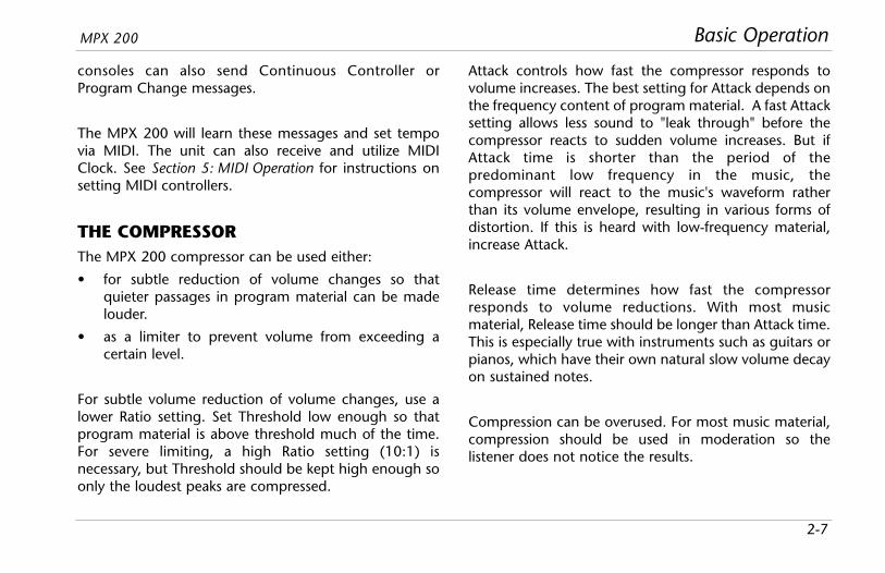
THE COMPRESSORThe MPX 200 compressor can be used either:
• for subtle reduction of volume changes so thatquieter passages in program material can be madelouder.
• as a limiter to prevent volume from exceeding acertain level.
For subtle volume reduction of volume changes, use alower Ratio setting. Set Threshold low enough so thatprogram material is above threshold much of the time.For severe limiting, a high Ratio setting (10:1) isnecessary, but Threshold should be kept high enough soonly the loudest peaks are compressed.
Attack controls how fast the compressor responds tovolume increases. The best setting for Attack depends onthe frequency content of program material. A fast Attacksetting allows less sound to "leak through" before thecompressor reacts to sudden volume increases. But ifAttack time is shorter than the period of thepredominant low frequency in the music, thecompressor will react to the music's waveform ratherthan its volume envelope, resulting in various forms ofdistortion. If this is heard with low-frequency material,increase Attack.
Release time determines how fast the compressorresponds to volume reductions. With most musicmaterial, Release time should be longer than Attack time.This is especially true with instruments such as guitars orpianos, which have their own natural slow volume decayon sustained notes.
Compression can be overused. For most music material,compression should be used in moderation so thelistener does not notice the results.

Basic Operation Lexicon
2-8
COMPRESSOR PARAMETERSTurn the Adjust knob to change the selectedcompressor parameter. An appropriate value for thatparameter will be displayed. Successive presses of theEdit button will sequence through the followingcompression parameters, then back to the four programparameters (see page 2-4).
Ratio (Off, 2-1, 3-1, 5-1, and 10-)
Determines the compression ratio of the compressor.Available ratios include 2:1, 3:1, 5:1, and 10:1.
Threshold (-32 to 0dB)
Determines the signal threshold below which thecompressor is inactive.
Attack (4, 8, 16, 30, 60, 125)
Controls the attack time (in milliseconds) of thecompressor.
Release (4, 8, 16, 30, 60, 125, 250)
Controls the release time (in milliseconds) of thecompressor.
After changing parameter settings, the MPX 200 willwait 4 seconds, then "timeout" and revert to displayingthe active program number on the display.
BYPASSThe Bypass button can be used to force the unitto pass only dry audio, to mute the outputsimmediately, or to mute the inputs to theloaded program. Its function depends on the setting ofthe System Mode parameter Bypass Mode. When BypassMode is set to Dry, the unit sends only dry, unprocessedaudio to the outputs. When set to Full Mute (Qui), theunit mutes the outputs. When set to Input Mute (Inp),the unit mutes the inputs only. Running effects willcontinue their natural decay. When enteringBypass Mode, “byP” will show on the displayand the Bypass LED will light.

When new programs are stored in a User Bank location,any program that was previously stored at that locationwill be automatically replaced.
Basic OperationMPX 200
2-9
STORING PROGRAMSAfter editing a preset, all changes made to the Edit andCompressor parameters can be stored in any of the 64User locations. To store a program:
1. Press the Store button. The Store LED willlight to indicate that the MPX 200 storefunction is armed, and the display will read “U1” orthe first empty User Bank location.
The Tap/Cancel LED will also light toindicate that pressing this button will exitwithout saving the current program.
2. To store a program in a User Bank location otherthan the one displayed, turn the Adjust knob untilthe desired location appears on the display. The LoadLED will light if the selected location already containsa program. The LED will not light if the selectedlocation is empty.
3. Press Store again to store the program.
The Store LED will flash rapidly while the store operationis occurring, and will no longer be lit when store iscomplete. The Edit and Load LEDs will also no longer belit when the saved version becomes the current activeprogram.
CAUTION
SELECTING AND LOADING USERPROGRAMSDuring program selection, turning the Adjust knob tonumbers higher than the presets selects the userprograms, indicated by the letter “U.” To load a userprogram, select the desired user program and press theLoad button.
If the selected User Bank location is empty, the EFFECTSand ROUTING (DUAL) LEDs will not light and pressingLoad will have no function.

3Overview ......................................................................................3-2
System Mode Parameters..............................................................3-3
System Mode

System Mode Lexicon
3-2
The MPX 200 provides ultimate control with its SystemMode parameters. System Mode can be used to changethe behavior of the MPX 200, as well as access itsinternal MIDI dumps and features.
To enter System Mode, press and hold Bypassfor approximately 2 seconds. The Bypass LEDlights and the display flashes "SyS" to indicatethat System Mode is active. When “SyS” stopsflashing, the display will read "Out" for Output Level, thefirst System Mode parameter.
Note:In System Mode, all other front panel controls aredisabled until System Mode is deactivated.However, the MPX 200 is still able to pass andprocess audio while in this mode.
System Mode parameters available in this mode areshown in the table on the next page. To select aparameter, press Bypass. Each press of the Bypass buttonwill advance to the next available parameter. A symbolic3-character string will appear on the digital display to
indicate which parameter is selected. When the lastparameter is selected, the next press of the Bypassbutton returns to the Output Level parameter. (Thisbehavior is similar to that of the Edit parameters.)
To view the current setting of the selected parameter,turn the Adjust knob one click. The display will show thecurrent setting. To change a parameter setting, turn theAdjust knob further (either left or right). (In someinstances, such as MIDI dumps, the Store LED lights.Press Store to execute the dump. The display willindicate the current state.)
Note: System Mode parameter settings are automaticallysaved. Changes made to these parameters areapplied immediately (except Global CompressorMode), and retained until settings are changedagain.
To exit System Mode, press and hold Bypassagain for approximately 2 seconds. The displaywill flash “Sto” to verify that changes have been stored.

Parameter Settings Display
10. MIDI Channel Off, 1 -16, All
11. MIDI Program On*, OffChange
12. MIDI Clock Receive On*, Off
13. MIDI OUT/THRU Thr, Out*
14. Auto Load On, Off*
15. Dump User Bank (1, 17, 33, 49)
16. Dump CurrentProgram
17. Dump SystemData
18. Clear User Bank
19. Initialize
* Indicates default setting
System ModeMPX 200
3-3
Parameter Settings Display
1. Output Level Off, -31 to 0dB*
2. Input Source Ana*, Dig
3. Digital Output Pro*, Dry
4. Global Mix Mode Glo, Pro*
5. Bypass Mode Dry*, Qui, Inp
6. Program Load Dry*, Qui
7. Global Tempo Mode Glo, Pro*(Tap)
8. Global Compressor Glo, Pro*Mode
9. Patching On*, Off
* Indicates default setting
SYSTEM MODE PARAMETERS

System Mode Lexicon
3-4
1. Output Level (Off, -31 to 0dB)
Adjusts overall output level of the MPX 200. This isthe first parameter displayed when System Mode isactivated.
2. Input Source (Ana, Dig)
Selects either analog (Ana) or digital (Dig) input. TheMPX 200 will mute when Input Source is set to Digand no digital signal is present.
Note: When Input Source is set to Digital (Dig)and the unit is in Load Mode or Edit Mode,the display will show a message for 4seconds whenever it detects any change inS/PDIF input status. For example, if the input cableis removed while connected and receiving a valid44.1kHz S/PDIF signal, the display will show "nod"for "no digital". When a digital signal is re-acquired, it will show "dig".
3. Digital Output (Pro, Dry)
Selects the source for the digital output. When set toPro, the digital output is the same as the analogoutputs. Its mix level will reflect the current settingof the Mix parameter. When set to Dry, the digitaloutput is the input. This setting is useful forrecording dry tracks while still providing processingat the analog outputs.
4. Global Mix Mode (Glo, Pro)
Controls the mix level that is applied when a newprogram is loaded. Mix levels are stored with eachprogram. When Global Mix Mode is set to Program(Pro), the unit applies the stored mix level of theselected program to that program as it is loaded.When set to Global (Glo), the unit ignores stored mixlevels and applies the current mix level to eachprogram as it is loaded.
Note:Global Mix Mode appears on the display as “d-p”for dry-processed. This name was chosen becausea digital display cannot show either “m” or “x.”

System ModeMPX 200
3-5
5. Bypass Mode (Dry, Qui, Inp)
Sets the function of Bypass. When set to Dry, the unitsends only dry, unprocessed audio to the outputs.When set to full mute (Qui), the unit mutes theoutputs. When set to input mute (Inp), the unitmutes the inputs only. Running effects will continuetheir natural decay.
6. Program Load (Dry, Qui)
Controls the processing of incoming audio signalsduring program load. When set to mute (Qui), theunit mutes during program load. When set to bypass(Dry), the unit sends only dry, unprocessed audio tothe outputs.
7. Global Tempo Mode (Tap) (Glo, Pro)
Controls the tempo setting that is applied when anew program is loaded. A tempo setting is storedwith each program. When Global Tempo Mode is setto Program (Pro), the unit applies the stored temposetting of each program as it is loaded. When set toGlobal (Glo), the unit applies the current temposetting to each program as it is loaded.
8. Global Compressor Mode (Glo, Pro)
Controls the compression settings that are appliedwhen a new program is loaded. Compressionsettings are stored with each program. When GlobalCompressor Mode is set to Program (Pro), the unitapplies the stored setting of each program as it isloaded. When set to Global (Glo), the unit appliesthe current compression setting to each program asit is loaded.
Note:The Program (Pro) setting for Global CompressorMode does not take effect until a new program isselected.
9. Patching (On, Off)
Enables and disables Learned Patches. When set toOn, the unit responds to Learned Patches. When setto Off, the unit ignores Learned Patches, preventingaccidental changes.

System Mode Lexicon
3-6
10. MIDI Channel (Off, 1 to 16, All)
Selects the MIDI Channel for MPX 200 messages.When set to Off, the unit ignores messages sent onall MIDI channels. When set within a range of 1 to16, the unit responds to messages sent on theselected MIDI channel. When set to All, the unitresponds to messages sent on all MIDI channels.
11. MIDI Program Change (On, Off)
Enables and disables MIDI Program Changemessages. When set to On, the unit responds toMIDI Program Change messages. When set to Off,the unit ignores MIDI Program Change messages,preventing accidental changes.
12. MIDI Clock Receive (On, Off)
Enables and disables MIDI Clock messages. When setto On, Tap Tempo is changed by incoming MIDImessages. When set to Off, the unit ignores MIDIClock messages, preventing accidental changes.
13. MIDI OUT/THRU (Thr, Out)
Controls the function of the MIDI OUT/THRUconnector. When set to Thru (Thr), the unit canforward - but cannot generate or modify - MIDImessages. When set to Out, the unit can generate itsown MIDI Dumps.
Note:MIDI dumps can only be performed when theSystem Mode parameter MIDI OUT/THRU is set toOut.
14. Auto Load (On, Off)
Determines whether the front panel Load buttonmust be pressed to load selected programs. Whenset to On, programs will automatically load 3/4second after the Adjust knob stops turning. When setto Off, programs will not load until the Load buttonis pressed.

System ModeMPX 200
3-7
Note:When any MIDI dumps are received by the MPX200 from an external device, they areautomatically applied or stored.
15. Dump User Bank (1, 17, 33, 49)
Executes a MIDI Dump of User Bank programs to anexternal MIDI device, such as a sequencer. Theseprograms can be dumped back to the unit. This isuseful to preserve User Bank programs from deletionprior to restoring defaults.
User programs are dumped in groups of 16,depending on the group selected with the Adjustknob. Group 1 refers to user programs 1 to 16.Group 17 refers to user programs 17-32. Group 33refers to user programs 33-48. Group 49 refers touser programs 49 to 64.
Once a group is selected, press the front panel Storebutton to execute the Dump. When dumped back,the group will be returned to its original User Banklocation.
16. Dump Current Program
Executes a MIDI Dump of the currently activeprogram. This allows programs to be saved to anexternal MIDI device. Press the front panel Storebutton to execute the dump. When dumped back,the program will automatically become thecurrently active program.
17. Dump System Data
Executes a MIDI Dump of all System Mode settingsand Learned Patches. Press the front panel Storebutton to execute the dump. When dumped back,the System Mode settings and Learned Patches willtake effect immediately.

System Mode Lexicon
3-8
18. Clear User Bank
Arms a procedure to erase the contents of the UserBank. Press the front panel Store button to executethis procedure and return the User Bank to itsfactory-default condition.
Note:The User Bank cannot be cleared while a Userprogram is running.
19. Initialize
Arms a procedure to restore parameters, SystemMode parameters, User Bank programs, and LearnedPatches to their factory-default conditions. Press thefront panel Store button to execute this procedure.The display will show “rSt” while this is taking place.This requires about one minute to complete.
Warning:
Executing either Clear User Bank or Initialize will erase allprograms stored in the User Bank.
WARNING

4Overview ......................................................................................4-2
Single Programs............................................................................4-3Plate • Gate • Hall • Chamber • Ambience • Room • Tremolo • Rotary •Chorus • Flange • Detune • Pitch • Delay, Echo
Compressor ................................................................................4-16
Special FX ...................................................................................4-17Preset 117
Dual Programs ............................................................................4-19Flange-Delay • Pitch-Delay • Chorus-Delay • Delay-Reverb • Flange-Reverb •Pitch-Reverb • Chorus-Reverb • Mono Split Delay • Mono Split Reverb •Dual Mono
Program Descriptions

Program Descriptions Lexicon
4-2
The 240 programs in the MPX 200 are designed toprovide a full array of high caliber ambience, reverb,delay, pitch shift, and other effects. While auditioningthese programs, it is recommended to vary the Adjustand EQ parameters.
The Adjust and EQ parameters have been carefullycustomized for each individual program. In many cases,they control several effect parameters simultaneously toprovide simple control of a complicated editing process.For example, in many Chamber and Room programs,Adjust controls the "liveness" of the space by changingdecay, EQ, and early reflections at the same time. Adjusthas a range of 0 to 127 to make it compatible with MIDIcontrol.
This section provides a general description of each MPX200 Program Bank. It includes tables that list theprograms available in each bank, and detail the functionof the Adjust knob and Tap button for these programs.(The Tap button only applies to programs that usetempo-controlled modulation rates or delay times.)
Program Bank Programs1. Plate 1-92. Gate 10-193. Hall 20-294. Chamber 30-395. Ambience 40-496. Room 50-597. Tremolo 60-648. Rotary 65-699. Chorus 70-7410. Flange 75-7911. Detune 80-8412. Pitch 85-8913. Delay, Echo 90-10414. Compressor 105-10915. Special FX 110-11916. Flange-Delay 120-12917. Pitch-Delay 130-13918. Chorus-Delay 140-14919. Delay-Reverb 150-15920. Flange-Reverb 160-16921. Pitch-Reverb 170-17922. Chorus-Reverb 180-18923. Mono Split Delay 190-20424. Mono Split Reverb 205-22425. Dual Mono 225-240

Program DescriptionsMPX 200
4-3
SINGLE PROGRAMS
PLATEPlate reverb was originally generated by a large, thinsheet of metal suspended upright under tension onsprings. Transducers attached to the plate transmitted asignal that made the plate vibrate - making any soundsbroadcast through it seem to be occurring in a largeopen space.
The Plate programs synthesize the sound of metal plateswith high initial diffusion and a relatively bright, coloredsound. These programs are designed to be heard as partof the music, mellowing and thickening the initial sound.They are a popular choice for enhancing pop music,particularly percussion.
Plate Presets Adjust Tap
1 Small Plate Liveness –
2 Medium Plate Liveness –
3 Large Plate Liveness Pre-Delay *
4 Tap Pre-Delay MidRT Pre-Delay *
5 Tape Slap ips (7.5/15) –
6 Rich Plate MidRT Pre-Delay *
7 Large&Bright MidRT Pre-Delay *
8 Vocal Plate Liveness Echo
9 Drum Plate Liveness –* (1/32 Note)

Program Descriptions Lexicon
4-4
GATEGated reverbs were originally created by feeding areverb, such as a metal plate, through an analog gatedevice. The decay time was set to instant, and the holdtime varied the duration of the sound.
The Gate programs provide a fairly constant sound withno decay until the reverb is cut off abruptly. Theseprograms work well on percussion - particularly on snareand toms - but it is recommended to experiment withother sound sources as well.
Note:When Time is altered with the Adjust knob, theeffect is re-loaded, causing audio to briefly mute orbypass to dry audio, depending on the setting ofthe System Mode Parameter Program Load (seepage 3-5).
Gate Presets Adjust Tap
10 StraightGate Time –
11 Slope Down Time –
12 Drum Gate Slope Pre-Delay *
13 140ms TapPre Slope Pre-Delay *
14 240ms TapPre Slope Pre-Delay *
15 340ms TapPre Slope Pre-Delay *
16 440ms TapPre Slope Pre-Delay *
17 540ms TapPre Slope Pre-Delay *
18 Inverse Time –
19 Dark Inverse Time –* (1/32 Note)

Program DescriptionsMPX 200
4-5
HALLLexicon's Hall programs recreate the acoustics of actualplaces, from grand reverberant enclosures to smallconcert halls.
The clean reverberation of the Hall programs is designedto add spaciousness, while leaving the source materialunchanged. In addition to general instrumental andvocal applications, the Hall programs are a good choicefor giving separately recorded tracks the sense ofbelonging to the same performance.
Hall Presets Adjust Tap
20 Small Hall MidRT –
21 Medium Hall MidRT –
22 Large Hall MidRT –
23 Small Church MidRT –
24 Large Church MidRT –
25 Jazz Hall MidRT –
26 Dance Hall MidRT –
27 Synth Hall MidRT –
28 Concert Hall MidRT –
29 Gothic Hall MidRT –

Program Descriptions Lexicon
4-6
CHAMBERHistorically, recording studio chambers were oddlyshaped rooms with a loudspeaker and set ofmicrophones to pick up the ambience in various parts ofthe room.
The stereo Chamber programs produce even, relativelydimensionless reverberation, with little change in coloras the sound decays. The initial diffusion is similar to theHall programs, but the sense of space and size is muchless obvious. This characteristic, along with the low colorof the decay tail, makes these programs useful on a widerange of material. They are especially useful on spokenvoice, giving a noticeable increase in loudness with verylow color.
Chamber Presets Adjust Tap
30 Brick Wall MidRT –
31 Basement MidRT –
32 Live Concert Liveness Echo Delay
33 Drum Chamber MidRT –
34 Moves on... Liveness –
35 Live Chamber Liveness –
36 VocalChambr1 Liveness Echo Delay
37 VocalChambr2 Liveness Echo Delay
38 Wide Chamber Liveness –
39 PCM60: Large MidRT –

Program DescriptionsMPX 200
4-7
AMBIENCEAmbience gives warmth, spaciousness, and depth to aperformance without coloring the direct sound, and iscommonly used to add a room sound to recorded musicor speech. In music recording, ambience can realisticallyadd distance to close-mic’ed signal.
The Ambience programs simulate reflections from roomsurfaces with random reflections, a gradual decay ofoverall level, and a gradual narrowing of bandwidth.
The Mix parameter adds depth to these programs,emulating the movement of a coincident pair ofmicrophones away from the sound source into the room.
Ambience Presets Adjust Tap
40 Announcer Decay –
41 VerySmallAmb Decay –
42 SmallAmb Decay –
43 MidSizeAmb Decay –
44 Studio "D" Decay –
45 Bright Amb Decay –
46 Dark Amb Decay –
47 Marble Foyer Decay –
48 Smooth Amb Decay –
49 Guitar Amb Decay –

Program Descriptions Lexicon
4-8
ROOMRoom programs emulate actual rooms where there is amore apparent sense of being in a small, live place.Room programs are very useful on drums and percussionand can also be applied to electric guitar tracks.
Room Presets Adjust Tap
50 Bedroom Walls –
51 Tiled Room LF Boost –
52 Studio "C" MidRT –
53 Small Room Liveness –
54 Studio "B" MidRT –
55 Rehearsal Room MidRT –
56 Studio "A" MidRT –
57 Large Room MidRT –
58 Fat Space MidRT –
59 Chunky Space MidRT –

Program DescriptionsMPX 200
4-9
TREMOLOTremolo is a rhythmic change in loudness, commonlyemployed as an expressive technique by vocalists andwind instrument players. It is also one of the oldestelectronic effects - frequently used with electric guitar,electric piano, and occasionally vocals. Differenttremolo effects are largely determined by the rate andwaveform shape of the loudness change (fast or slow,smooth or sharp). If the effect is used in a stereo mix, theleft and right can be synchronized in a variety of ways toproduce dramatic side-to-side motion.
The Tremolo programs offer a variety of tremolo shapes(square, sawtooth, triangle, sine, and rectified sine). Thesynchronization of the left and right sides can beadjusted to produce stereo effects. As the tremolo ratesare set with Tap, it is easy to match the tempo of themusic. The Adjust knob (Phase) can be used to set leftand right channel waveforms out-of-phase, resulting in apanning motion.
All of these programs should be used with Mix set to fullwet (100%). By adding more dry to the wet/dry mix,Mix effectively sets the depth of the tremolo. Take careto make the rate work with the tempo of the music, asTremolo is essentially a rhythmic effect .
Tremolo Presets Adjust Tap
60 RectSineTap Phase Rate (1/8 Note)
61 Square Tap Phase Rate (1/4 Note)
62 Sine Tap Trpl Phase Rate (1/4 Note)
63 Triangle Phase Rate (1/4 Note)
64 Sawtooth Phase Rate (1/4 Note)

Program Descriptions Lexicon
4-10
ROTARYRotary speaker cabinets were originally designed toprovide a majestic vibrato/choir effect for electronictheater and church organs. The most well known rotaryspeaker is the Leslie™ Model 122, which has twocounter-rotating elements: a high-frequency horn and alow-frequency drum with slow and fast speeds. As thespinning elements change speed, the sound generated istruly magical. The swirling, spacious effect is hard todescribe, but is instantly recognizable.
The rotary effect is a detailed simulation of a Leslie-stylecabinet. The input signal is split into high and low-frequency bands. The rotation effect is created by asynchronized combination of pitch shifting, tremolo,and panning. Like the physical model, the high (horn)and low (drum) frequencies are “spun” in oppositedirections. Horn and drum speeds are independent, andare designed with acceleration and decelerationcharacteristics to simulate the inertia of the originalmechanical elements.
A virtual requirement for any organ sound, the Rotaryprograms also sound great with guitar and electric pianorhythm parts. In fact, they are great alternatives tochorus and tremolo effects for any sound source.
All of these programs should be used with Mix set to fullwet (100%)to achieve the full effect.
Rotary Presets Adjust Tap
65 Rot SlowFast Switch –
66 Rot Slow Resnce –
67 Rot SpeedAdj Speed –
68 Rot TapRate1 Balance Rate
69 Rot TapRate2 Resnce Rate

Program DescriptionsMPX 200
4-11
CHORUSChorus effects multiply the original audio source tocreate a lush, full sound. Traditionally used to fatten uptracks and to add body to guitar without coloring theoriginal tone, chorus effects are also used in combinationwith echoes, plates, and other reverb effects.
The stereo Chorus programs use six independentlyrandomized delay voices panned across the stereo field.These programs, inherited from Lexicon's PCM 80,generate a rich, airy effects that simulates the sound ofmultiple sources from a single source. These programsare stunning on acoustic or clean electric guitar.
All of these programs should be used with Mix set to fullwet (100%) to achieve the full richness of the 6-voicechorus.
Chorus Presets Adjust Tap
70 Chorus1 Resnce –
71 Chorus2 Resnce –
72 Chorus3 Diffusn –
73 Slap Chorus1 Diffusn –
74 Slap Chorus2 Depth –

Program Descriptions Lexicon
4-12
FLANGEFlange effects were originally created by simultaneouslyrecording and playing back identical material on twotape recorders, then using hand pressure against theflange of the tape reels to slow down first one machine,then the other. The result was a series of changing phasecancellations and reinforcements, with a characteristicswishing, tunneling, and fading sound.
The MPX 200 stereo flanger has two 2-Tap delays - oneper channel. The first tap is fixed, and the second sweepspast it. Mixing the two delay taps together creates theflanging effect.
All of these programs should be used with Mix set to fullwet (100%) to achieve the full flange effect.
Flange Presets Adjust Tap
75 Flng Lite Speed —
76 Flng Lite180 Resnce —
77 Flng Med180 Speed —
78 Flng Deep Resnce —
79 Flng Deep180 Resnce —

Program DescriptionsMPX 200
4-13
DETUNEDetune effects add a delayed/pitch-shifted version of theoriginal source - thickening up the sound. They can beparticularly effective when used to simulate double-tracking. They are also great alternatives to choruseffects, adding the richness of a chorus without theaudible sweep caused by the chorus rate.
The 4-voice stereo Detune programs have one pair ofvoices per channel. As more detune amount is applied(with Adjust), the pair grow more out of tune, providinga lush sound without the need for mixing in a dry signal.All of these programs should be used with Mix set to fullwet (100%) to achieve the full effect.
Detune Presets Adjust Tap
80 Detune Mild Dtuning –
81 Detune Med&Warm Dtuning –
82 Detune Heavy Dtuning –
83 Det Xtreme Dtuning –
84 Pitch Detune Dtuning –
PITCHAltering the pitch of a sound allows a variety of effects,from subtle detuning to the creation of harmonies andchords. The stereo polyphonic Pitch programs allowcomplete program material or monophonic sources tobe shifted within a range of two octaves down to oneoctave up.
For pitch correction, use these programs with Mix set tofull wet (100%). For harmonization, use the desiredamount of wet-to-dry Mix.
Pitch Presets Adjust Tap
85 Pch Chrmatic Pitch –
86 Pitch Fine Pitch –
87 Pch 4th-5ths Pitch –
88 Pch PowerInV Pitch –
89 Vocal Chorus Depth –

Program Descriptions Lexicon
4-14
DELAY, ECHODelays and echoes repeat a sound a short time after itfirst occurs. The simplest (and oldest) delay effect is tapeslap - a single repeat about 100ms after the originalsound. Tape slap was often used on Elvis Presley’s voiceand rockabilly guitar tracks.
Tape slap becomes tape echo when the output of thetape is fed back into the input (feedback). This turns asingle repeat into a series of repeats, each a little softerand a little darker than the last. This darkening ischaracteristic of the analog tape recording process.
Digital echoes do not have this characteristic; eachrepeat has the same exact timbre. For digital echoes,loudness is the only difference from repeat to repeat.
Tape and digital echoes are both useful, but different.Tape echo is warmer, allowing the original sound todistinguish itself. Digital echo presents a “perfect” copyof the original sound.
The Delay and Echo programs include mono (5.5 seconds), stereo (2.7 seconds), and 6-voice multi-tapeffects. Each program can be used for tape or digitaldelay or echo effects. When the Adjust parameter is setto a value between 0 and 63, digital delay effects areproduced. Each repeat is the same timbre, but softer.When the Adjust parameter is set to a value between 64and 127, tape effects are produced. Each repeat isdarker and softer.
In programs 90 to 97, the Adjust parameter sets theamount of feedback with an increasing number ofrepeats as the setting is increased. Delay time is set withTap. Each program is preset with a different usefulrhythm. In programs 98 to 104, the amount of feedbackis preset and the Adjust parameter determines the delaytime.
With all delay and echo effects, note the way the repeatsfall rhythmically to the beat. The most typical delay andecho patterns are those that lock with the tempo of themusic.

Program DescriptionsMPX 200
4-15
Delay, Echo Presets Adjust Tap
90 Dly Mono Tap Feedbk Delay Time
91 DlyStereo Tap Feedbk Delay Time
92 Dly ShuflTap Feedbk Delay Time
93 Dly Dot8 Tap Feedbk Delay Time
94 Dly 8+3plTap Feedbk Delay Time
95 Dly Pong Tap Feedbk Delay Time
96 Dly XfbkTap1 Feedbk Delay Time
97 Dly XfbkTap2 Feedbk Delay Time
98 Dly Mono Time: –0 to 5.5s
99 Dly Stereo Time: –0 to 2.7s
Delay, Echo Presets Adjust Tap
100 Dly TapeSlap Time: –3 3/4 to 30ips
101 Multi Bounce Time: –0 to 100ms
102 MultiInverse Time: –0 to 400ms
103 Multi Linear Time: –0 to 400ms
104 Multi Pong Time: 0 to –150ms + Fbk

Program Descriptions Lexicon
4-16
COMPRESSORThe compressor in the MPX 200 is a stand-alone controlthat modulates the level feeding the other activeeffect(s). It has no effect on the dry signal coming out ofthe Mix control (or the Bypass signal when the SystemMode parameter Bypass Mode is set to Dry).Compression on a dry signal is obtained by using adelay-echo algorithm with delay times set to 0. Thus,the Mix parameter must be set to full wet (100%) for thisto work properly. This is the default setting when theSystem Mode parameter Global Mix Mode is set toProgram (Pro).
Programs 107, 108, and 109 use a parallel reverb-delayalgorithm to obtain compression on both a dry and wetsignal. To use these programs, observe the following:
• Keep the Mix parameter set to full wet (100%), thedefault setting when the System Mode parameterGlobal Mix Mode is set to Program (Pro). The drysignal will be obtained as a compressed "delayed"echo with the delay time set to 0.
• Adjust the reverb level by changing the Balanceparameter between full left (0%) and about 40%.(Typical values should be between 5% and 10%.)
Compressor Presets Adjust Tap
105 3:1 Compression Gain Make-up -
106 10:1 Compression Gain Make-up -
107 Small Hall/ Decay Pre-Delay * Compression
108 Medium Hall/ Decay Pre-Delay *Compression
109 Large Hall/ Decay Pre-Delay *Compression
* (1/32 Note)

Program DescriptionsMPX 200
4-17
SPECIAL FX
Special FX Presets Adjust Tap
110 Infinite Reverb Bass X-Over Frequency Echo
111 The Abyss ± Pitch Bend –
112 Jet Flange Tone Rate (Whole Note)
113 Chorus Verb Decay –
114 Rotary Delay Dly/Echo Time: 0-150ms+Fbk Rate (1/4 Note)
115 LowRumble Decay Time –
116 Echoes:Beats Echoes per Beat Delay Time
117 Stereo Stage * See page 4-18
118 Dream Sequence ± Shift Amount –
119 Infinite Delay Echo Feedback Delay Time

Program Descriptions Lexicon
4-18
PRESET 117This preset supplies reverb while preserving stereoimaging in a live stage setup. Stereo imaging ispreserved with time delay rather than conventionalleft/right panning, so a proper channel mix is maintainedin both left and right speakers. To use this program,observe the following:
• Use the MPX 200 in-line between mixer and houseamps, not as an effect that is mixed back into themain left and right signals.
• On your mixer, pan the input channel for eachmusician fully to that musician’s side of the stage.
• Keep the Mix parameter set to 50%, the defaultsetting when the System Mode parameter GlobalMix Mode is set to Program (Pro).
• Adjust the reverb level by setting the Balance param-eter between full left (-50) and about -10. (Typicalvalues should be between -45 and -40.)
• Set the Width parameter for the distance betweenthe speakers at each side of the stage. The programloads with an assumed width of approximately 20feet. The available Adjust knob range is 10 to 50 feet.These values assume that most audiencemembers are seated within 30 degrees of either sideof the stage centerline. The Adjust setting can beincreased if many audience members are seatedfurther to the sides of the stage, but otherwise itshould be kept as low as possible.

Program DescriptionsMPX 200
4-19
DUAL PROGRAMSThe dual programs combine either Delay with Reverb, oreither Delay or Reverb with Flange, Pitch, or Chorus. TheLvl/Bal parameter controls the relative balance of eacheffect in the combination.
Dual programs use four routing configurations: DualStereo (Parallel), Cascade, Mono Split, and Dual Mono,which are organized as follows:
• The first six programs in Banks 16 to 22 are set up inDual Stereo (Parallel) configuration - two stereoprograms placed side-by-side that receive andoutput stereo audio from both the left and rightchannels. The last four programs in each bank are setup in Cascade configuration - two stereo programs,one placed after the other. For example, in Flange-Delay, Flange passes its stereo signal to Delay.
• Banks 22 and 23 are arranged in Mono Splitconfiguration, which is similar to Dual Stereo(Parallel), except one effect (Flange) receives audiofrom the left input and the other effect (Delay)receives audio from the right input. Both effects thenoutput stereo audio.
• Dual Mono programs are grouped in the last bank(24). In these programs, one program (Flange)appears on the left channel only and the otherprogram (Delay) appears on the right channel only.
Generally, the Lvl/Bal parameter controls the balance ofthe two effects in each dual program. In the Cascadevariations, rather than simply controlling balance, theAdjust knob varies the amount of the first effect or drysignal that is fed into the second effect.
Dual Mono
Flange
Delay
L
R
L
R
Mono Split
Flange
Delay
L
R
L
R
Cascade
Flange DelayLR
LR
Dual Stereo (Parallel)
Flange
Delay
L
R
L
R

Program Descriptions Lexicon
4-20
FLANGE-DELAY
Flange-Delay Presets Adjust Tap Routing
120 Flng Tap Feedbk Delay Time (1/4 Note) Dual Stereo (Parallel)
121 Flng .8Tap Feedbk Dotted 1/8 Note Dual Stereo (Parallel)
122 Flng 3plTap Feedbk 1/8 Note Triplet Dual Stereo (Parallel)
123 Flng PongTap Feedbk Delay Time (1/4 Note) Dual Stereo (Parallel)
124 Flng Xfeed Time: 0-150ms — Dual Stereo (Parallel)
125 Flng Bounce Time: 0-200ms, Feedbk — Dual Stereo (Parallel)
126 Flng>Tap Feedbk Delay Time (1/4 Note) Cascade
127 Flng>Fbk Time: 0-150ms, Feedbk — Cascade
128 Flng>Pong Feedbk Delay Time (1/4 Note) Cascade
129 Flng>Bnce Time: 0-200ms, Feedbk — Cascade
Cascade
Flange DelayLR
LR
Dual Stereo (Parallel)
Flange
Delay
L
R
L
R

Program DescriptionsMPX 200
4-21
PITCH-DELAY
Pitch-Delay Presets Adjust Tap Routing
130 5th Tap Pitch Delay Time Dual Stereo (Parallel)
131 8ve 3pTap Pitch Delay Time Dual Stereo (Parallel)
132 8ve 8+3plTap Pitch Delay Time Dual Stereo (Parallel)
133 3rd4thPong Pitch Delay Time Dual Stereo (Parallel)
134 4th5th Xfeed Pitch Delay Time Dual Stereo (Parallel)
135 5th6th Xfeed Pitch Delay Time Dual Stereo (Parallel)
136 8ve>Xfeed Pitch Delay Time Cascade
137 5th>Xfeed Pitch Delay Time Cascade
138 MajMin>Fbk Pitch Delay Time Cascade
139 StepUp>Tap Pitch Delay Time Cascade
Cascade
Pitch DelayLR
LR
Dual Stereo (Parallel)
Pitch
Delay
L
R
L
R

Program Descriptions Lexicon
4-22
CHORUS-DELAY
Chorus-Delay Presets Adjust Tap Routing
140 Chor Tap Feedbk Delay Time Dual Stereo (Parallel)
141 Chor 8Tap Feedbk Delay Time Dual Stereo (Parallel)
142 Chor 8+3pl Feedbk Delay Time Dual Stereo (Parallel)
143 Chor Pong Feedbk Delay Time Dual Stereo (Parallel)
144 Chor Repeat Time – Dual Stereo (Parallel)
145 Chor Bounce Time – Dual Stereo (Parallel)
146 Chor>Tap Feedbk Delay Time Cascade
147 Chor>Repeat Time — Cascade
148 Chor>Pong Feedbk Delay Time Cascade
149 Chor>Bnce Time – Cascade
Cascade
Chorus DelayLR
LR
Dual Stereo (Parallel)
Chorus
Delay
L
R
L
R

Program DescriptionsMPX 200
4-23
DELAY-REVERB
Delay-Reverb Presets Adjust Tap Routing
150 Tap Small MidRT Delay Time Dual Stereo (Parallel)
151 3plTapMidSz MidRT Delay Time Dual Stereo (Parallel)
152 8+3pl Large MidRT Delay Time Dual Stereo (Parallel)
153 Pong Small MidRT Delay Time Dual Stereo (Parallel)
154 Xfeed MidSz MidRT Delay Time Dual Stereo (Parallel)
155 Xfeed Large MidRT Delay Time Dual Stereo (Parallel)
156 Tap>Room Liveness Delay Time Cascade
157 8+3pl>Large MidRT Delay Time Cascade
158 Xfeed>Room Liveness Delay Time Cascade
159 Xfeed>Large MidRT Delay Time Cascade
Cascade
Delay ReverbLR
LR
Dual Stereo (Parallel)
Delay
Reverb
L
R
L
R

Program Descriptions Lexicon
4-24
FLANGE-REVERB
Flange-Reverb Presets Adjust Tap Routing
160 LiteFl Small MidRT Speed (Whole Note) Dual Stereo (Parallel)
161 LiteFl MidSz MidRT Speed (Whole Note) Dual Stereo (Parallel)
162 LiteFl Large MidRT – Dual Stereo (Parallel)
163 Deep Fl Small MidRT – Dual Stereo (Parallel)
164 Deep Fl MidSz MidRT – Dual Stereo (Parallel)
165 Deep Fl Large MidRT – Dual Stereo (Parallel)
166 LiteFl>Small MidRT Speed (Whole Note) Cascade
167 LiteFl>Room Liveness Speed (Whole Note) Cascade
168 Deep Fl>Large MidRT – Cascade
169 Deep Fl>Room Liveness – Cascade
Cascade
Flange ReverbLR
LR
Dual Stereo (Parallel)
Flange
Reverb
L
R
L
R

Program DescriptionsMPX 200
4-25
PITCH-REVERB
Pitch-Reverb Presets Adjust Tap Routing
170 3rd4th Room Pitch Pre-Delay (1/32 Note) Dual Stereo (Parallel)
171 4th5th Room Pitch Pre-Delay (1/32 Note) Dual Stereo (Parallel)
172 5th6th Room Pitch Pre-Delay (1/32 Note) Dual Stereo (Parallel)
173 8ve MidSiz Pitch Pre-Delay (1/32 Note) Dual Stereo (Parallel)
174 Power MidSiz Pitch Pre-Delay (1/32 Note) Dual Stereo (Parallel)
175 Detune Room Dtuning Pre-Delay (1/32 Note) Dual Stereo (Parallel)
176 Fine>Small Pitch Pre-Delay (1/32 Note) Cascade
177 Power>Large MidRT Pre-Delay (1/32 Note) Cascade
178 4th>MidSiz MidRT Pre-Delay (1/32 Note) Cascade
179 8ve>MidSiz MidRT Pre-Delay (1/32 Note) Cascade
Cascade
Pitch ReverbLR
LR
Dual Stereo (Parallel)
Pitch
Reverb
L
R
L
R

Program Descriptions Lexicon
4-26
CHORUS-REVERB
Chorus-Reverb Presets Adjust Tap Routing
180 Chor1 Small MidRT – Dual Stereo (Parallel)
181 Chor1 MidSiz MidRT – Dual Stereo (Parallel)
182 Chor1 Large MidRT – Dual Stereo (Parallel)
183 Chor2 Small MidRT – Dual Stereo (Parallel)
184 Chor2 MidSiz MidRT – Dual Stereo (Parallel)
185 Chor2 Large MidRT – Dual Stereo (Parallel)
186 Chor1>Room Liveness – Cascade
187 Chor2>Room Liveness – Cascade
188 Chor3>Room Liveness – Cascade
189 Chor1>Small MidRT – Cascade
Cascade
Chorus ReverbLR
LR
Dual Stereo (Parallel)
Chorus
Reverb
L
R
L
R

Program DescriptionsMPX 200
4-27
MONO SPLIT DELAY
Mono Split Delay Presets Adjust Tap
190 Flng Tap Feedbk 1/4 Note
191 Flng Pong Feedbk 1/4 Note
192 Flng Xfeed Time –
193 Flng Bnce Time –
194 Deep Fl Dly Time –
195 5th Tap Pitch Delay Time
196 8ve 3plTap Pitch Delay Time
197 4th5th Xfeed Pitch Delay Time
198 5th6th Xfeed Pitch Delay Time
199 PchFine Tap Pitch Delay Time
200 Chor Tap Feedbk Delay Time
201 Chor Pong Feedbk Delay Time
202 Chor Xfeed Time –
203 Chor Bnce Time –
204 Chor Inverse Time –
Mono Split
Flange
Delay
L
R
L
R

Program Descriptions Lexicon
4-28
MONO SPLIT REVERB
Mono Split Reverb Presets Adjust Tap
205 Tap MidSiz MidRT Delay Time
206 Pong Large MidRT Delay Time
207 Bnce MidSz MidRT Delay Time
208 Xfeed Small MidRT Delay Time
209 Xfeed MidSiz MidRT Delay Time
210 LiteFL MidSz MidRT Speed
211 LiteFl Large MidRT –
212 DeepFl Small MidRT –
213 DeepFl MidSz MidRT –
214 DeepFl Room Liveness –
215 4th5th Room Pitch Pre-Delay 1/32
216 5th6th Room Pitch Pre-Delay 1/32
217 4ths Large MidRT –
218 8ve MidSz MidRT –
219 PchFin MidSz Pitch –
220 Chor1 Small MidRT –
221 Chor1 Large MidRT –
Mono Split
Flange
Delay
L
R
L
R

Program DescriptionsMPX 200
4-29
Mono Split Reverb Presets Adjust Tap
222 Chor2 MidSiz MidRT –
223 Chor2 Large MidRT –
224 Chor3 MidSiz MidRT –
Mono Split
Flange
Delay
L
R
L
R

Program Descriptions Lexicon
4-30
DUAL MONO
Dual Mono Presets Adjust Tap
225 Tap Small MidRT Delay Time
226 Tap MidSz MidRT Delay Time
227 Tap Large MidRT Delay Time
228 Tap Room Liveness Delay Time
229 DeepFl Tap Feedbk Speed (1/4 Note)
230 DeepFl Dot 8 Feedbk Speed (dotted 1/4 Note)
231 8ves Tap Pitch Delay Time
232 8ves 3pl Pitch Delay Time
233 Chor2 Tap Feedbk Delay Time
234 Chor2 Dot8 Feedbk Delay Time
235 LiteFl Large MidRT Speed
236 DeepFl Large MidRT Speed
237 8ves MidSz MidRT Pre-Delay 1/32
238 4ths Large MidRT Pre-Delay 1/32
239 Chor1 Room Liveness --
240 Chor2 Room Liveness --
Dual Mono
Flange
Delay
L
R
L
R

5MIDI Behavior ...............................................................................5-2
Assigning a MIDI Channel for Program Load.................................5-2
MIDI Bank Select and Program Change Messages ........................5-2
Learning Other MIDI Patches ........................................................5-3
Clearing a Learned Assignment.....................................................5-4Learnable Front Panel Controls and Assignable MIDI Sources
MIDI Clock....................................................................................5-6
MIDI Dumps .................................................................................5-6
MIDI Sysex Messages ....................................................................5-6
MIDI Implementation Chart ..........................................................5-7
MIDI Operation

MIDI Operation Lexicon
5-2
MIDI BEHAVIORThe MPX 200 "learns" Program Change and ContinuousController messages in Learn Mode. Learned Patches aresupported for the front panel Bypass, Tap, andCompressor buttons, as well as the EDIT parameters.
• The Bypass, Tap, and Compressor buttons can bepatched to Program Change messages.
• Program Change messages can be used to loadprograms.
• Program Change messages 0 to 99 are reserved forexecuting program loads.
ASSIGNING A MIDI CHANNEL FORPROGRAM LOADA single, selectable MIDI channel is used for all MPX 200messages. This channel can be assigned in System Modewith the MIDI Channel parameter (see page 3-6).
When the System Mode parameter MIDI Channel is setto Off, the unit ignores messages sent on all MIDI
channels. When set within a range of 1 to 16, the unitresponds to messages sent on the selected MIDI channel.The default MIDI channel is 1. When set to All, the unitresponds to messages sent on all MIDI channels.
Note:A MIDI channel should be assigned before MIDIfeatures are used.
MIDI BANK SELECT AND PROGRAMCHANGE MESSAGESMIDI Bank Select messages can be sent to the MPX 200with Continuous Controller 32. Bank 0 containsprograms 1 to 99; Bank 1 contains programs 100 to 199;Bank 2 contains programs 200 to 240; and Bank 3 servesas the User Bank. Bank selection is also accomplishedwhen a program is cued with the Adjust knob.
A MIDI Program Change message causes the selectedprogram to load from the selected bank, provided theselected program exists and the System Mode parameterMIDI Program Change has been set to On.

MIDI OperationMPX 200
5-3
For example, a Bank Select value of 1 followed by aProgram Change value of 57 will cause the MPX 200 toload program 157. A Bank Select value of 2 followed bya Program Change value of 57 will cause the MPX 200to do nothing, because there is no program 257. A BankSelect value of 0 followed by a Program Change value of0 will cause the MPX 200 to do nothing, because thereis no program 0. Likewise, a Program Change messagerequesting an empty location in the User Bank will beignored.
LEARNING OTHER MIDI PATCHESThe MPX 200 recognizes Pitch Bend, AfterTouch, andMIDI Continuous Controllers 1 to 31 and 33 to 119 - inaddition to Program Change messages - to manipulatethe audio controls.
To Learn a Continuous Controller or other MIDI message:
1. Press Store and Tap simultaneously to enterLearn Mode. The Store and Tap LEDs willlight to indicate Learn Mode is active, and “lrn” willappear on the display.
2. Press the desired button (for example, Tap orBypass), or the Edit button to choose the desirededitable parameter.
3. Send a Program Change message or move the MIDIcontroller through its full range. To use only afraction of the controller range, limit your movementto the desired range. The Edit LED will flash toindicate incoming MIDI activity.
4. Press Store to commit to the assignment.The Store LED will flash rapidly and “Sto”will appear on the display.
To assign another front panel control to a MIDIcontroller or Program Change message, repeat steps2 to 4.
5. Press Store and Tap simultaneously to exit LearnMode. The Store LED will flash rapidly to indicatethat Learn Mode is being exited.
. . . continued on page 5-4

MIDI Operation Lexicon
5-4
Note:When a MIDI controller is assigned to Tap, movingit upward through the mid-point of its Learnedrange will execute a "press" of the front panelbutton. When a MIDI controller is assigned to theBypass or Compressor buttons, moving above orbelow its mid-point will toggle the control on or off.
Some MIDI controllers do not allow repeated ProgramChange messages to be sent with a single button. Toassist these controllers, the unit also recognizes the nexthighest Program Change message with each ProgramChange message it learns for Bypass and Tap. Forinstance, if Program Change 20 is learned as the sourcefor Bypass, Program Change 21 will also control Bypassfunctions. To avoid conflicting Bypass and Tapassignments, leave a space between the assignments forthese two buttons.
CLEARING A LEARNED ASSIGNMENT
1. Press Store and Tap simultaneously to enterLearn Mode. The Store and Tap LEDs willlight to indicate Learn Mode is active, and “lrn” willappear on the display.
2. Select the desired front panel control to clear (forexample, Mix, Lvl/Bal, Adjust, or Bypass).
3. Press Store to clear the assignment. The Store buttonwill flash rapidly and “Clr” will appear on the display.
To clear another front panel assignment, repeat steps2 and 3.
4. Simultaneously press Store and Tap to exit LearnMode. The Store button will flash rapidly ifassignments have been changed.

MIDI OperationMPX 200
5-5
LEARNABLE FRONT PANEL CONTROLS AND ASSIGNABLE MIDI SOURCES
Front Panel MIDI Controllers MIDI Pgm Change Default ContinuousControl 1 to 31, 33 to 119 100 to 127 Controller No.
Mix Yes No 1
Adjust Yes No 2
EQ Yes No 3
Lvl/Bal Yes No 4
Ratio Yes No 5
Threshold Yes No 6
Attack Yes No 7
Release Yes No 8
Bypass Yes Yes 18
Tap/Cancel Yes Yes 17
Compressor (On/Off) Yes Yes 16

MIDI Operation Lexicon
5-6
MIDI SYSEX MESSAGESMIDI Sysex messages can be used to access all algorithmparameters. More information about using this advancedfeature with the MPX 200 and other Lexicon products isavailable at www.lexicon.com. The website offersinstructions, sample messages, and a complete table ofparameter Sysex addresses.
Note:Executing MIDI Sysex messages is a complicatedprocess. Please observe the cautionary notesincluded on the website.
MIDI CLOCKThe MPX 200 recognizes MIDI Clock messages andapplies the tempo (40 to 400 bpm) to programs that usethe Tap Tempo feature. Connect a MIDI device thatoutputs MIDI Clock, such as the MPX R1 Foot Controlleror a MIDI sequencer, to the MPX 200 MIDI IN connectorto have the MPX 200 automatically recognize and beginto process MIDI Clock messages. When the tempo of theconnected device changes, the unit will automaticallyadjust its delay times and modulation rates to match thenew tempo.
This feature can be disabled with the System Modeparameter MIDI Clock Receive (see page 3-6).
MIDI DUMPSMIDI Dumps can be used to save user programs, theselected program, or the System Mode settings andLearned Patch assignments to a storage device (typicallya MIDI sequencer). MIDI Dumps are performed inSystem Mode (see page 3-7).

MIDI OperationMPX 200
5-7
MIDI IMPLEMENTATION CHART
Function Transmitted Recognized Remarks
Basic Default X 1 Set as System Mode parameter MIDIChannel Channel X Off, 1-16, OMNI Channel (page 3-6)
Mode Default Mode 2Messages X XAltered X
Note X XNumber True Voice
Velocity Note ON X X (Off=9n v=0)Note OFF X X
After Keys X X Used as controllerTouch Channels X OX Learned
Pitch Bender X OX Used as controllerLearned
Control X OX 1 to 119 (0 and 32 used as Bank Select)Change Learned
. . . continued on page 5-8

MIDI Operation Lexicon
5-8
MIDI IMPLEMENTATION CHART (continued)
Function Transmitted Recognized Remarks
Program True # X 1 to 99 For Bank 0 (programs 1 to 99) Change 0 to 99 For Bank 1 (programs 100 to 199)
0 to 40 For Bank 2 (programs 200 to 240) 1 to 64 For Bank 3/User Bank (U1 to U64)*
System Lexicon O O Lexicon ID = 06/Product ID = 21 (decimal)Exclusive Real-Time X X Device ID = MIDI Channel
non Real-Time X X 0 to 15 = 1 to 16
System :Song Pos X X:Song Sel X X
Common :Tune X X
System :Clock X OReal Time :Commands X X
Aux :Local ON/OFF X XMessages :All Notes OFF X X
:Active Sense:Reset X X
Mode 1: OMNI ON, POLY Mode 3: OMNI OFF, POLY O: Yes X: NoMode 2: OMNI ON, MONO Mode 4: OMNI OFF, MONO
* Responds only if a program has been stored in the corresponding User location.

ASpecifications ................................................................................A-2
Declaration of Conformity ............................................................A-3
Appendix

Appendix Lexicon
A-2
Audio Inputs (2)Level -30dBu to +4dBuImpedance 500K unbalanced for
direct instrument input (unit detects a mono input on the right input)1/4" connectors
Audio Outputs (2)Level +8dBu typicalImpedance 75 Ohms for
headphone output(right only used formono output; left onlyused for stereoheadphones)1/4" connectors
Digital Audio Output24-bit digital S/PDIF output (always active)
Sample Rate 44.1kHzConnector Coaxial, RCA type
Digital Audio InputDigital S/PDIF input
Sample Rate Supports 44.1kHz onlyConnector Coaxial, RCA type
FootswitchTip/Ring/Sleeve phone jack for Bypass andTap (optional)
Frequency ResponseWet/Dry 20Hz-20kHz, ±1dB
THD+N<0.05%, 20Hz-20kHz
Dynamic RangeA/A >95dB typical,20Hz-
20kHz, unweightedA/D >100dB typical, 20Hz-
20kHz, unweightedD/A >100dB typical, 20Hz-
20kHz, unweighted
ConversionA/D, D/A 24-bits Sample Rate 44.1kHz
Crosstalk>55dB
Internal Audio Data PathDSP 24-bit
Power Requirements100-120/220-240V~50 - 60Hz, 25W
DimensionsWidth 19 inches (483mm)Height 1.75 inches (45mm)Depth 5.5 inches (140mm)
WeightUnit 3.15 pounds (1.41 kg)
EnvironmentOperating 32 to 104°F (0 to 40°C)TemperatureRelative 95% non-condensingHumidity
SPECIFICATIONS
Specifications are subject to change without notice.

AppendixMPX 200
A-3
DECLARATION OF CONFORMITY
Application of Council Directive(s): 89/336/EEC and 93/68/EEC
Standard(s) to which Conformity is Declared: EN 55103-1, EN 55103-2, and EN 60065: 1998
Manufacturer: Lexicon, Inc., 3 Oak Park, Bedford, MA 01730-1441 USAThe equipment identified here conforms to the Directive(s)and Standard(s) specified above.
Type of Equipment: Dual Channel Processor
Model: Lexicon MPX 200
Date: January 2001
Lexicon, Inc.Vice President of Engineering
3 Oak ParkBedford, MA 01730-1441 USA
Tel: 781-280-0300Fax: 781-280-0490

IIndex
AC Input Connector. . . . . . . . . . . . . . . . 1-6Adjust Knob. . . . . . . . . . . . . . . 1-5, 2-2, 4-2Adjust Parameter. . . . . . . . . . . . . . . 2-5, 4-2Ambience Programs . . . . . . . . . . . . . . . . 4-7Appendix . . . . . . . . . . . . . . . . . . . A1 to A3Attack Parameter . . . . . . . . . . . . . . . . . . 2-8Audio Levels, Setting . . . . . . . . . . 1-8 to 1-9Audio Tap . . . . . . . . . . . . . . . . . . 2-5 to 2-6Auto Load Parameter . . . . . . . . . . . . . . . 3-6Bank Select Messages. . . . . . . . . . 5-2 to 5-3Basic Operation . . . . . . . . . . . . . . 2-1 to 2-9Bypass. . . . . . . . . . . . . . . . . . . . . . . . . . 2-8Bypass Button . . . . . . . . . . . . . . . . . . . . 1-5Bypass Mode Parameter *. . . . . . . . . . . . 3-5Cascade Configuration . . . . . . . . . . . . . 4-19CD-ROM . . . . . . . . . . . . . . . . . . . . ix to xivChamber Programs . . . . . . . . . . . . . . . . 4-6
Chorus Programs . . . . . . . . . . . . . . . . . 4-11Chorus-Delay Programs . . . . . . . . . . . . 4-22Chorus-Reverb Programs . . . . . . . . . . . 4-26Clear User Bank * . . . . . . . . . . . . . . . . . . 3-8Clearing Learned Patches . . . . . . . . . . . . 5-4Clock, MIDI . . . . . . . . . . . . . . . . . . . . . . 5-6Compressor . . . . . . . . . . . . . . . . . . . . . . 2-7Compressor Button . . . . . . . . . . . . . . . . 1-5COMPRESSOR LEDs . . . . . . . . . . . . . . . . 1-4Compressor Parameters . . . . . . . . . . . . . 2-8Compressor Programs . . . . . . . . . . . . . 4-16Connectors. . . . . . . . . . . . . . 1-6 to 1-7, 1-8Cueing Programs . . . . . . . . . . . . . . . . . . 2-3Declaration of Conformity . . . . . . . . . . . A-3Delay, Echo Programs. . . . . . . . 4-14 to 4-15Delay-Reverb Programs . . . . . . . . . . . . 4-23Detune Programs. . . . . . . . . . . . . . . . . 4-13
Digital Output Parameter *. . . . . . . . . . . 3-4Dual Mono Configuration. . . . . . . . . . . 4-19Dual Mono Programs . . . . . . . . . . . . . . 4-30Dual Stereo (Parallel) Configuration . . . 4-19Dual Programs . . . . . . . . . . . . . 4-19 to 4-30Dump Current Program *. . . . . . . . . . . . 3-7Dump System Data * . . . . . . . . . . . . . . . 3-7Dump User Bank * . . . . . . . . . . . . . . . . . 3-7Dumps, MIDI . . . . . . . . . . . . . . . . . 3-7, 5-6Echo, Delay Programs . . . . . . . 4-14 to 4-15Edit Button . . . . . . . . . . . . . . . . . . . . . . 1-5EDIT Display . . . . . . . . . . . . . . . . . . . . . 1-5Editing Programs . . . . . . . . . . . . . . . . . . 2-4EFFECTS LEDs . . . . . . . . . . . . . . . . . . . . 1-4EQ Parameter . . . . . . . . . . . . . . . . . 2-5, 4-2Flange Programs . . . . . . . . . . . . . . . . . 4-12Flange-Delay Programs. . . . . . . . . . . . . 4-20
* Indicates System Mode parameters and functions.

Index Lexicon
I-2
Flange-Reverb Programs . . . . . . . . . . . . 4-24Footswitch. . . . . . . . . . . . . . . . . . 1-6 to 1-7Front Panel . . . . . . . . . . . . . . . . . 1-4 to 1-5Gate Programs. . . . . . . . . . . . . . . . . . . . 4-4Getting Started. . . . . . . . . . . . . . 1-1 to 1-9Global Compressor Mode Parameter * . . 3-5Global Mix Mode Parameter * . . . . . . . . 3-4Global Tempo . . . . . . . . . . . . . . . . . . . . 2-6Global Tempo Mode Parameter * . . . . . . 3-5Hall Programs . . . . . . . . . . . . . . . . . . . . 4-5Initialize * . . . . . . . . . . . . . . . . . . . . . . . 3-8INPUT Connectors . . . . . . . . . . . . . 1-7, 1-8Input Knob . . . . . . . . . . . . . . . . . . . . . . 1-4Input Source Parameter * . . . . . . . . . . . . 3-4Inspection Instructions . . . . . . . . . . ix to xivLearned Patches. . . . . . . . . . . . . . 5-3 to 5-5LEVEL LEDs L/R . . . . . . . . . . . . . . . . . . . 1-4Limited Warranty . . . . . . . Inside Back CoverLoad Button . . . . . . . . . . . . . . . . . . . . . 1-5Loading Programs . . . . . . . . . . . . 2-2 to 2-3Loading User Programs . . . . . . . . . . . . . 2-9Lvl/Bal Parameter . . . . . . . . . . . . . 2-5, 4-19MIDI Bank Select Messages . . . . . 5-2 to 5-3MIDI Behavior . . . . . . . . . . . . . . . . . . . . 5-2MIDI Channel Parameter * . . . . . . . . . . . 3-6
MIDI Clock . . . . . . . . . . . . . . . . . . . . . . 5-6MIDI Clock Receive Parameter * . . . . . . . 3-6MIDI Dumps. . . . . . . . . . . . . . . . . . 3-7, 5-6MIDI Implementation Chart . . . . . 5-7 to 5-8MIDI IN Connector . . . . . . . . . . . . . . . . 1-7MIDI Learned Patches . . . . . . . . . 5-3 to 5-5MIDI LED. . . . . . . . . . . . . . . . . . . . . . . . 1-5MIDI Operation . . . . . . . . . . . . . . 5-1 to 5-8MIDI OUT/THRU Connector . . . . . . . . . . 1-7MIDI OUT/THRU Parameter * . . . . . . . . . 3-6MIDI Program Change Messages . . 5-2 to 5-3MIDI Program Change Parameter *. . . . . 3-6MIDI Program Load Channel . . . . . . . . . 5-2MIDI, Setting Tempo via . . . . . . . 2-6 to 2-7MIDI Sysex Messages . . . . . . . . . . . . . . . 5-6Mix Parameter . . . . . . . . . . . . . . . . . . . . 2-4Mono Split Configuration . . . . . . . . . . . 4-19Mono Split Delay Programs . . . . . . . . . 4-27Mono Split Reverb Programs . . 4-28 to 4-29MPX 200, About the . . . . . . . . . . 1-2 to 1-3OUTPUT Connectors . . . . . . . . . . . . 1-7, 1-8Output Level Parameter * . . . . . . . . . . . . 3-4Parallel (Dual Stereo) Configuration. . . . 4-19Patching Parameter * . . . . . . . . . . . . . . . 3-5Pitch Programs . . . . . . . . . . . . . . . . . . 4-13
Pitch-Delay Programs . . . . . . . . . . . . . . 4-21Pitch-Reverb Programs . . . . . . . . . . . . . 4-25Plate Programs. . . . . . . . . . . . . . . . . . . . 4-3Power Switch. . . . . . . . . . . . . . . . . . . . . 1-5Preset 117 . . . . . . . . . . . . . . . . . . . . . . 4-18Program Banks. . . . . . . . . . . . . . . . . . . . 4-2Program Change Messages . . . . . 5-2 to 5-3Program Descriptions . . . . . . . . . 4-1 to 4-30Program Load Channel, MIDI . . . . . . . . . 5-2Program Load Parameter * . . . . . . . . . . . 3-5Program Parameters. . . . . . . . . . . 2-4 to 2-5Ratio Parameter . . . . . . . . . . . . . . . . . . . 2-8Rear Panel . . . . . . . . . . . . . . . . . . 1-6 to 1-7Release Parameter . . . . . . . . . . . . . . . . . 2-8Room Programs . . . . . . . . . . . . . . . . . . . 4-8Rotary Programs . . . . . . . . . . . . . . . . . 4-10Routing Configurations . . . . . . . . . . . . 4-19ROUTING (DUAL) LEDs . . . . . . . . . . . . . 1-4S/PDIF IN and OUT Connectors . . . . . . . 1-7Safety Instructions. . . . . . Inside Front Cover,
iv to viiiSelecting Programs . . . . . . . . . . . 2-2 to 2-3Selecting User Programs. . . . . . . . . . . . . 2-9Setting Audio Levels. . . . . . . . . . . 1-8 to 1-9Setting Tempo. . . . . . . . . . . . . . . 2-5 to 2-7
* Indicates System Mode parameters and functions.

IndexMPX 550
I-3
Single Programs. . . . . . . . . . . . . 4-3 to 4-15Specifications. . . . . . . . . . . . . . . . . . . . . A-2Special FX Programs. . . . . . . . . 4-17 to 4-18Store Button . . . . . . . . . . . . . . . . . . . . . 1-5Storing Programs . . . . . . . . . . . . . . . . . . 2-9SysEx Messages . . . . . . . . . . . . . . . . . . . 5-6System Mode . . . . . . . . . . . . . . . 3-1 to 3-8System Mode Parameters . . . . . . . 3-3 to 3-8Table of Contents . . . . . . . . . . . . . . . ii to iiiTap Tempo . . . . . . . . . . . . . . . . . . . . . . 2-5Tap/Cancel Button . . . . . . . . . . . . . 1-5, 4-2Tempo Features . . . . . . . . . . . . . . 2-5 to 2-7Threshold Parameter . . . . . . . . . . . . . . . 2-8Tip/Ring/Sleeve Connector . . . . . . . . . . . 1-7Tremolo Programs . . . . . . . . . . . . . . . . . 4-9Unpacking Instructions . . . . . . . . . . ix to xivUser Programs . . . . . . . . . . . . . . . . . . . . 2-9VOLTAGE LINE SWITCH . . . . . . . . . . . . . 1-6Warranty . . . . . . . . . . . . . Inside Back Cover
* Indicates System Mode parameters and functions.

LIMITED WARRANTY
Lexicon, Inc. offers the following warranty on this product:
What is the Duration of this Warranty?This warranty will remain in effect for one (1) year from the original date ofpurchase.
Who is Covered?This warranty may be enforced by the original purchaser and subsequentowners during the warranty period, provided the original dated sales receiptor other proof of warranty coverage is presented at time of service.
What is Covered?This warranty covers all defects in material and workmanship on this product,except as specified below. The following are not covered:1. Damage resulting from
A. Accident, misuse, abuse, or neglect.B. Failure to follow instructions contained in the User Guide.C. Repair or attempted repair unauthorized by Lexicon, Inc.D. Failure to perform recommended periodic maintenance.E. Causes other than product defects, including lack of skill,
competence, or experience on the part of the owner.2. Damage occurring during any shipment of this product. Claims for
shipping damages must be made with the carrier.3. Damage to a unit that has been altered, or on which the serial number
has been defaced, modified, or removed.
What Expenses will Lexicon, Inc. Assume?Lexicon, Inc. will pay all labor and material expenses for covered items.Payment of shipping charges is discussed in the next section of the warranty.
How is Service Obtained?When this product needs service, write, telephone, or fax Lexicon, Inc. torequest information about where the unit should be taken or sent. Whenmaking a written request, please include your name, complete address, and
daytime telephone number; the product model and serial numbers; and adescription of the problem. Do not return the unit to Lexicon, Inc. withoutprior authorization.
When Shipping a Product for Service . . .1. Pay any initial shipping charges, which are the responsibility of the
owner. If necessary repairs are covered by this warranty, Lexicon, Inc. willpay return shipping charges to any destination in the United States usingthe carrier of our choice.
2. Pack the unit securely. Package insurance is strongly recommended.3. Include a copy of the original dated sales receipt. (A copy of the original
dated sales receipt must be presented when warranty service is required.)4. Do not include accessories such as power cords or user guides unless
instructed to do so.
What are the Limitations of Implied Warranties?Any implied warranties, including warranties of merchantability and fitness fora particular purpose, are limited in duration to the length of this warranty.
What Certain Damages are Excluded?Lexicon’s liability for a defective product is limited to repair or replacement ofthat product, at our option. Lexicon, Inc. shall not be liable for damagesbased on inconvenience; loss of use of the product; loss of time; interruptedoperation; commercial loss; or any other damages, whether incidental,consequential, or otherwise.
How do State Laws Relate to this Warranty?Some states do not allow limitations on the duration of implied warrantiesand/or the exclusion or limitation of incidental or consequential damages. Assuch, the above limitations may not apply. This warranty is not enforceableoutside of North America. This warranty provides specific legal rights.Additional rights may be provided by some states.
A Harman International Company
Lexicon, Inc3 Oak ParkBedford, MA 01730-1441USA
Tel 781-280-0300Fax..781-280-0490
www.lexicon.com
Customer SupportTel 781-280-0300Fax..781-280-0495 (Sales)Fax..781-280-0499 (Service)

A Harman International Company
Lexicon, Inc.3 Oak ParkBedford, MA 01730-1441 USATel 781-280-0300Fax 781-280-0490www.lexicon.com
Customer SupportTel 781-280-0300Fax 781-280-0495 (Sales)Fax 781-280-0499 (Service)
Lexicon Part No. 070-14738 | Rev 2 | 02/02

Percussion2 Bass Drum . . . . . . . . . . . . . . . . . . . . . .(0:30)3 Snare Drum 1 . . . . . . . . . . . . . . . . . . .(0:46)4 Snare Drum 2 . . . . . . . . . . . . . . . . . . .(0:38)5 Stick . . . . . . . . . . . . . . . . . . . . . . . . . .(0:38)6 Shaker . . . . . . . . . . . . . . . . . . . . . . . .(0:39)7 Claps . . . . . . . . . . . . . . . . . . . . . . . . .(0:41)8 Conga . . . . . . . . . . . . . . . . . . . . . . . .(0:48)9 Table & Udo . . . . . . . . . . . . . . . . . . . .(0:54)
10 Percussion 1 . . . . . . . . . . . . . . . . . . . .(1:00)11 Percussion 2 . . . . . . . . . . . . . . . . . . . .(1:23)12 Open Drum Kit . . . . . . . . . . . . . . . . . .(1:16)13 Funk Drum Kit . . . . . . . . . . . . . . . . . . .(1:08)14 Fusion Drums & Bass . . . . . . . . . . . . . .(0:33)15 Funk Drums & Bass . . . . . . . . . . . . . . .(0:33)16 Fusion Drums & Bass . . . . . . . . . . . . . .(1:18)17 Broadband Click . . . . . . . . . . . . . . . . .(0:38)18 Narrowband Click . . . . . . . . . . . . . . . .(0:38)
Guitar19 Acoustic Chords 1 . . . . . . . . . . . . . . . .(0:59)20 Acoustic Chords 2 . . . . . . . . . . . . . . . .(2:13)21 Acoustic Chords 3 . . . . . . . . . . . . . . . .(1:12)22 Acoustic Leads . . . . . . . . . . . . . . . . . . .(0:41)23 Acoustic Stops . . . . . . . . . . . . . . . . . . .(0:36)24 Electric Solo . . . . . . . . . . . . . . . . . . . .(0:44)25 Electric Clean & Fast . . . . . . . . . . . . . .(0:32)26 Electric Dirty . . . . . . . . . . . . . . . . . . . .(1:24)27 Electric Crunch . . . . . . . . . . . . . . . . . .(0:38)
Bass28 Slap (120 bpm) . . . . . . . . . . . . . . . . . .(1:29)29 Fingered (120 bpm) . . . . . . . . . . . . . .(0:49)
Do not play Track 1 on an audioCD player. It contains the computerportion of the disc and will emit full-scale digital noise.
Dry TracksThis card lists the dry tracks included on the CD-ROM enclosed with this user guide.
A Harman International Company
WARNING

Voice30 Female Vocal 1 . . . . . . . . . . . . . . . . . .(0:43)31 Female Vocal 2 . . . . . . . . . . . . . . . . . .(0:56)32 Female Vocal 3 . . . . . . . . . . . . . . . . . .(0:20)33 Male Vocal 1 . . . . . . . . . . . . . . . . . . . .(1:20)34 Male Vocal 2 . . . . . . . . . . . . . . . . . . . .(0:21)35 Vocal Group 1 . . . . . . . . . . . . . . . . . . .(0:26)36 Vocal Group 2 . . . . . . . . . . . . . . . . . . .(0:28)
Keyboard37 Hammond 1 . . . . . . . . . . . . . . . . . . . .(0:12)38 Hammond 2 . . . . . . . . . . . . . . . . . . . .(0:07)39 Rhodes . . . . . . . . . . . . . . . . . . . . . . . .(0:59)
Horns40 Horn Section 1 . . . . . . . . . . . . . . . . . .(1:23)41 Horn Section 2 . . . . . . . . . . . . . . . . . .(1:36)42 Sax Solo . . . . . . . . . . . . . . . . . . . . . . .(0:30)43 Tenor Sax Solo . . . . . . . . . . . . . . . . . . .(2:21)
Miscellaneous44 Flute Solo . . . . . . . . . . . . . . . . . . . . . .(0:24)45 Accordian Solo . . . . . . . . . . . . . . . . . .(0:35)
Dual Mono (Left/Right)46 Kick/Snare . . . . . . . . . . . . . . . . . . . . . .(0:30)47 Kick/Bass . . . . . . . . . . . . . . . . . . . . . . .(0:37)48 African Bell/Slit Drum . . . . . . . . . . . . . .(0:43)49 Acoustic Guitar/Vocal . . . . . . . . . . . . . .(0:23)50 Electric Guitar/Vocal . . . . . . . . . . . . . . .(1:31)51 Church Guitars . . . . . . . . . . . . . . . . . .(0:36)52 Ms. Pride/Xavier . . . . . . . . . . . . . . . . .(1:04)
Post53 Ambulance . . . . . . . . . . . . . . . . . . . . .(0:19)54 Motorcycle . . . . . . . . . . . . . . . . . . . . .(1:08)55 Street Noise . . . . . . . . . . . . . . . . . . . . .(1:00)56 Propeller Place . . . . . . . . . . . . . . . . . . .(0:58)57 Jet Airplane . . . . . . . . . . . . . . . . . . . . .(1:02)58 Pipe Band . . . . . . . . . . . . . . . . . . . . . .(1:20)59 TV Music . . . . . . . . . . . . . . . . . . . . . . .(0:18)60 Monologue . . . . . . . . . . . . . . . . . . . . .(1:06)
TOTAL TIME . . . . . . . . . . . . . . . . . . . . . .(54:31)