Embed Size (px)
Citation preview

6059
1/1
11.2
019
1
Installation and Maintenance Manual
Before you install this cavity slider, ensure you open the attached boxes and read the enclosed information carefully.
IMPORTANT INFORMATION
ZG00078
6059
1/2
11.2
019
2
Quick Start Guide ....................................................................................................................3
Preparation for Installation ....................................................................................................4
Installing the Unit in the Opening .........................................................................................6
Electrical Installation ..............................................................................................................8
Safety Beam Installation ........................................................................................................9
Finishing the Installation ......................................................................................................10
Commissioning .....................................................................................................................11
Operation ...............................................................................................................................11
Removal of Door and Belt ....................................................................................................12
Controller Specifications ......................................................................................................14
Maintenance .........................................................................................................................15
Sample Control Layout ........................................................................................................15
Default Input Configuration .................................................................................................15
SMC Input Wiring .................................................................................................................16
SMC Overview ......................................................................................................................16
Trouble Shooting ..................................................................................................................17
Components Checklist ..........................................................................................................18
Maintenance Checklist .........................................................................................................19
Contents

6059
1/3
11.2
019
3
8
HEAT SINKS FOR SMC COMPONENTS
2 X 6mm2 FLEX SUPPLIED ON 100m ROLLS BY CS FOR DOORS
3-WAY MOLEX SNR PLUGMOTOR PHASE WIRES
MOTOR HALL EFFECT WIRESS
AUX OUTPUTS FROM SMCCONFIGURABLE VIA SMC VIEW
SAFETY BEAM INPUTS (2 SETS)
CLEAN CONTACT INPUTS 1 - 3CONFIGURABLE VIA SMC VIEW
POWERED DEVICE INUT4 CONFIGURABLE VIA SMC VIEW12VDC/24VDC MICRO JUMPER
POWERED DEVICE INUT5 CONFIGURABLE VIA SMC VIEW12VDC/24VDC MICRO JUMPER
20AMP BALDE FUSE REMOVABLE
USER INTERFACE INPUT RJ45 PIN 1 - PIN 1 WIRINGRS485 FULL DUPLEX
CANUS INTERFACE 1 RJ12
CANBUS INTERFACE 2 RJ12
PSU COMMS RJ11 PIN 1 - PIN 1 WIRING RS485 HALF DUPLEX
DIP SWITCHES FOR HARDWARE SETTINGSSEE TABLE
JUMPERS FOR POWERED DEVICE VOLTAGE SELECTION 12VDC/24VDC
2-WAY MOLEX SNR PLUG24VDC MAIN POWER
CLEAN CONTACT INPUTS 6CONFIGURABLE VIA SMC VIEW
RJ45 SERIAL COMMS POWER 5VDC/12VDCMICOR JUMPER SELECT
J-TAG PROGRAMMER HEADER
SPI-BUS HEADER PLUG INMODULE PCBJUMP PIN 12(Vol Sel) and 8 (Vcc)on Power up to reset to defaults as per DIP switch setting
LEDS TO INDICATE STATUS AS PER TABLE
DIP Switch Descriptons
RJ11 RS-485 Half Duplex
RJ45 RS-485 Full Duplex
RJ PLUG PIN ORDERVIEW FROM BOTTOM
1 2 3 4 5 6 7 8
LED Function Table
Dip Switch ON OFF1 CAN Open CAN Terminate2 Motor CW to Open Motor CCW to Open3 BN42-23 Motor BN42-33 Motor4 Default Settings 1 Default Settings 25 RJ11 RS485-PSU RJ11 RS485-SMC View6 SMC View Std SMC View + OLED
Pin Colour Label1 White/Orange Stripe CnVss2 White/Green Stripe Vcc 12/5VDC3 Whiote/Blue Strip RxB4 Blue Solid RxA5 White/Brown Stripe TxB6 Brown Solid TxA7 Green Solid GND8 Orange Solid Reset
Pin Colour Label1 Yellow NC2 Green Data B3 Red Data A4 Black 0VLED Colour LED ON LED OFF LED Flashing
1 Green 5VDC GOOD 5VDC Fault NA2 Red 24VDC GOOD 24VDC Fault NA3 Red 12VDC GOOD 12VDC Fault NA4 Green Safety Beam 2 Good Safety Beam 2 Distrupted Safety Beam 2 Good, Ignored5 Green Safety Beam 1 Good Safety Beam 1 Distrupted Safety Beam 1 Good, Ignored6 Green PC Comm Task Running PC Comm Task Crashed PC Comm Task Send/Receive7 Green Door Fault Normal Operation Door Trial Exired - Code required8 Red Door Open Door Not Open No Known Open Position9 Red Door Opening Door Not Opening Door Failed to Open 10 Red Door Closing Door Not Closing Door Failed to Close11 Red Door Closed Door Not Closed No Known Close Position
QUICK START
1 READ BEFORE YOU START
3 DO THE CYCLE TEST
2 INSTALL
4 LINE & FINISH
5 SERVICE
5 ROUGH IN WIRING
Read the Installation and Maintenance Manual FULLY before beginning the installation
Once the unit is physically installed into the opening, aligned correctly and has been checked that it is moving freely then it should be connected to the power temporarily (you can run an extension cord if required) and complete the cycle test (page 8).
Failure to follow the following steps carefully may be costly and time consuming.Charge out rates for repairs, components and associated travel costs will apply.
Install wall linings, taking care to follow the instructions on how to finish the access covers for a neat, tidy finish. Ensure you plug labelled switches correctly back together. Take care not to pinch or stretch any electrical wiring when lining.
Don’t paint over the safety beams! Ensure you inform your painter! EXTRA CARE MUST BE TAKEN IN AND AROUND THE SAFETY BEAM WIRES LOCATED IN THE VERTICAL DOOR JAMBS.
Safety Beam
On page 8 there are individual explanations of the purpose of each cable and the most common locations to run them to.Run all of your cables to the correct locations and ensure they are connected to the correct inputs on the red controller.
SA#This unit is supplied:
with all supplied switches pre-wired for plug & play
with no switching devices supplied (Customer to organise)
with some of the switching devices pre-wired and the rest to be organised by the customer.
Commission included
Customer commissioning
This unit has been tested in our factory and filmed in operation. To request a copy of the video, email [email protected] and mention the SA# above.
BEFORE YOU BEGIN: Contact the CS AutoCav Manager on +64 9 276 0800 (NZ) or 1800-573-486 (AU) to go over installation notes specific to this unit or to request a quote for commissioning.
(BUT DO NOT LINE!)
(before lining walls)
Contact CS to ensure your service plan is in place for regular maintenance.
Install the unit the same as you would any manual CS Cavity Slider, taking into account the following points:
- Extra height above the track for packing and wiring See diagram page 6- Access panel handing and position See diagram page 10- Connection of switching devices and/or sensors Page 8- Track must be kept clean and free of dirt or swarf (no contamination at all)- Door slides freely without rubbing on anything. (Disconnect drive bar to check.)

6059
1/4
11.2
019
4
Preparation for Installation
WHAT YOU NEED TO KNOW FIRST
BEFORE YOU START
Construction of the wall. The wall referred to in these instructions is ex 100mm x 50mm wooden framework. In reality this may mean a 94mm x 47mm or 90mm x 45mm wooden framework. Although not shown, the unit covered in these instructions may also be fitted into other types of wall materials (steelstud, concrete, brick, etc.).
For concrete or masonry type walls: fix a 100mm x 50mm timber fixing plate into the opening on both sides and under the head.
Fix these in place with ø10mm x 98mm long countersunk masonry anchors at 400mm centres.
Lintel or trimmer sizes. CS AutoCav units are non-loadbearing units. They require the lintel (or trimmer, ceiling joist or structural component) directly above the track to span the full trim size opening width. Timber lintels sized from NZS3604/ AS1684 are acceptable if the weight of the door leaf/leaves is less than 75kg per metre of total door width. If heavier, specific design is required for all other kinds of structural components and for the timber lintels. Please consult your engineer.
The hole in the wall. Calculation of how big the hole in the wall framing should be to fit this unit:
CS AutoCav90 Single unit Height = door leaf height + 260mm
Width = (door leaf width x 2) + 30mm
Standard clearances under the door. With this CS AutoCav unit sitting hard on top of the concrete or timber floor, the clearance under the door leaf ranges between 22 - 30mm (adjustable). The majority of these standard clearances is taken up by the floor covering (e.g. carpet, tiles etc.).
Modified clearances under the door. If you require more than 30mm clearance under the door: pack the CS AutoCav unit off the floor by the extra amount you need.
If you need less than 22mm clearance under the door leaf (e.g. for polished timber floors) there are three options to do this:
A CS can supply special seals that can be fitted to the bottom of the door leaf.
B* A door leaf up to 15mm taller can be fitted.
C* The whole cavity can be made up to 15mm shorter.
(*B & C are only available when pre-ordered.)
Contamination of the top track. CS Automatic Units require the track running surface to be clean and free of any contamination or damage. For smooth reliable service, the tyres on the carriage should not be chipped, dented or have swarf embedded in the tyre.Please ensure you take extra care with the carriages to avoid any damage during the installation process.
Fixing cavity slider to the floor Installing the cavity slider 100% plumb and level will NOT guarantee a correctly sliding door. If any of the wall, lintel, floor and door are not plumb and straight this can cause the door to slide incorrectly into the pocket.
It is for this reason that the skirting block fixing (found at the base of the cavity slider behind the split jambs) is only secured once you have ensured door is running parallel to the cavity pocket.
1 Remove packaging and check components. Remove the transport support (if fitted). Retain the screws for fitting the track. Check for any transportation damage. Check that the track is free from dust or debris. If not done, this will affect the operation of the unit.
If anything looks out of specification or you are unsure, contact CS before beginning your install.
2 Refit the track to the unit Only necessary if the track has been removed (to help with transport).
With the frame standing upright, fit the track. The notched end in the underside of the track must be at the closing jamb end of the track.
Fit the following screws using a long screw driver:
Back stud to track #8 x 30 self tappers 2 off
Split jamb to track #8 x 50 self tappers 4 off
Intermediate stud to track #8 x 50 self tappers 4 off
Back stud
Cabling allowance
TrackSplit jamb
Intermediate stud
#8 x 50mm screws
#8 x 30mm screws

6059
1/5
11.2
019
5
Preparation for Installation
5-5.5mm20-21mm
Screwtube
Screwtube
Track
2 Note: There are 3 versions of the split jambs depending on the type ordered as shown (diagram A, B or C.) The appropriate holes to fit these will be pre drilled.
A
C
B
Track fixing screw tubes
3-Cell Split jamb
Make sure that the back stud holes line up with the track screw tubes.
85mm to centre
85mm to
centre
ø25mm x 13mm deep
140 x 30mm x 20mm deep
Custom shoulder cap screw
Tapped adaptor plate
Drive bar
3 Preparing your own door In the centre of the top of your door leaf, router out a 140 x 30mm x 20mm deep hole for the drive bar connector.
Drill two holes 85mm in from either edge of the top of your door leaf in the positions as marked.
3 Screw both mounting plates to the door with the mounting plates placed exactly in the centre of the door thickness.
At the bottom of the door leaf cut a groove to the dimensions and tolerances shown. Make it central of the door thickness and absolutely straight.
4 Fit the door (if not already fitted) Load the carriages into the notched end of the track and slide into place.
Position the door underneath the carriages and offer the mounting plate onto the wheel hanger shaft.
Depress the plunger using the bolt head and slide until the bolt snaps into locked position
Connect the drive bar to the door using long custom shoulder cap screws.
5 Fit the closing jamb (if supplied). Use 2 screws #8 x 25mm long, as supplied.
(For NCJ detail option the track should butt into the finished wall lining. Refer to the additional instruction sheet).
AluSealed units: Ensure the closing jamb plate is fitted to the top of the closing jamb as shown with the bent lug towards the face side of the closing jamb.
#8 x 25mm pan head screws
#8 x 25mm pan head screws
AluSealed closing jamb
AluSealed head jamb
#8 x 19mm hex head screw

6059
1/6
11.2
019
6 © Cavity Sliders Limited
Pack and nail closing jamb (first).
Aluminium back stud
Screw through prepunched holes
Aluminium split jamb
Fix with nail or Dynabolt
Closing jambPackingJack stud Framing stud
Two timber split jambs
Pack & nail closing jamb (second).
Distance same as at bottom
Distance same as at top
Door leaf
Lintel
Nog
Bottom plate assembly
4 Fix the closing jamb (if required). Plumb closing jamb. Use a level!
Pack and nail at 500mm centres to the jack stud through the recessed centre section of the closing jamb and packing.
First: fix the top of the closing jamb. Second: fix the bottom of the closing jamb.
For timber: use ø2.8mm x 60mm nails. For steel : use #8 self tapping screws. Ensure that the distances between the closing jamb
and the split jamb are the same. The distance at the bottom must never be
more than the distance at the top. Measure this carefully! Fix between the top and bottom. Use a straight edge to make sure that the closing jamb is straight.
Installing the unit in the opening
1 Place the whole unit into the framed opening in the wall. Check that the jack studs on both sides of the door opening are plumb in both directions.
2 Fix the aluminium back stud. Plumb-up the two timber split jambs. Use a level!
While keeping the timber split jambs plumb, pack behind the aluminium back stud as shown. Screw the aluminium back stud including the packing to the 100mm x 50mm jack stud through the pre-punched holes.
Timber studs: use #8 x 29mm wood screws. Steel studs: #8 x 29mm self-tapping screws.
3 Level the track. The track must be fitted level and straight. For Full-Height (FH) detail option: The bottom of the track should finish flush with the underside of the finished ceiling (refer to the additional instruction sheet).
Drive bar
Head jamb

6059
1/7
11.2
019
7
119
Lintel
Cabling allowance
Wooden cover plug
Head jamb(architraved option)
Pelmet block
Head jamb(grooved option)
Pre-drilledø8mm holefor masonry anchor
Door leaf
Skirting fixing block
A--A =parallel gap
Drill ø3mm nail hole
AA
AA
Equal
Equal
Skirting block fixing
Door
Ad
just
men
t
Parallel
Parallel
3-cell split jamb
TimberFormed split jamb
Installing the unit in the opening
5 Fix the bottom plate assembly. The door must slide parallel with the bottom plate assembly (see the 2 sets of black A-A arrows). If not, gently tap the front of the assembly to the left or right until it does.
The door should now slide smoothly and fit into the recess in the closing jamb, leaving parallel gaps on either side between the door leaf and the closing jamb. Fix the skirting block fixing to the floor only when the cavity pocket has been adjusted so that the door closes neatly into the closing jamb and slides parallel to the bottom plate of the cavity slider.
Fix bottom plate assembly to the floor as follows:
To concrete floors: Fix with ø8mm x 90mm masonry anchors through the pre-drilled holes in the skirting fixing blocks of the bottom plate. (See the red stamped arrow on the timber).
To timber floors: Fix the bottom plate assembly with ø3.15mm x 75mm nails on either side in the centre of the skirting fixing block thickness. (See the red stamped on the timber). Pre-drill ø3mm holes for these nails.
6 Adjust the door height. Use the small end of the spanner supplied to rotate the hexagonal nut at the bottom of the carriage hanger shaft.
To raise door: Rotate spanner from left to right. To lower door: Rotate spanner from right to left.
8 Check door alignment. For trouble free operation, perform the following checks:
Carefully move the door manually from fully open to fully closed, checking that it moves freely.
Check that the alignment when fully closed and fully open is plumb and true.
Note: The hanger shaft fits at the top into a self locking nut. If you lower the hexagonal nut too far, the shaft will become loose from the self locking nut. If the turning resistance suddenly feels much easier, you have gone too far.
If the belt has lifted (or dropped) from the above action, reposition the belt bracket by loosening the bolt holding this in place, level up and re-tighten.
7 Fit the head jambs (if not already fitted). Before fitting head jambs, check that you have the desired clearance under the door and that the door is plumb (instruction 6). Slide the head jamb into place between the vertical jambs. When installing a unit with NoClosingJamb (NCJ) detail, scribe to suit the distance between the split jamb and opposing wall. (Refer to the additional instruction sheet.)
‘Flush up’ the joints. Then screw them into place with the #8 x 32mm long countersunk head screws (as supplied). Gently tap wooden plugs to cover the screw heads.
To lower door
To raise door
Adjusting spanner
Plunger pin

6059
1/8
11.2
019
8
Electrical Installation Instructions
2 Initial Cycle Test Turn on power (you can run an extension cord if
required).
Wait 10 seconds.
Press test switch or activation device once.
Door will slowly fully open and pause (Door is learning open position).
Door will then quickly return to the position it started in then slowly fully close and remain closed (Door is learning close position).
Press switch once more.
Door will open fully, pause, then close fully.
This completes the test proving that the door is functioning.
Power down unit.
If plugs were removed then replace as recorded in the photograph from the first step.
3 Rough in wiring BEFORE lining walls A CS Autocav unit will have a combination of the
following cables, which will be clearly labelled and referenced on a wiring diagram provided.
The most common cables are individually explained below:
A External activation (White 6 core security cable) Run this to where activation is desired to be positioned on the ‘outside’ or ‘secure’ side of the unit. May be identified by red sticker.
B Internal activation (White 6 core security cable) Run this to where activation is desired to be positioned on the ‘inside’ or ‘exit free’ side of the unit. May be identified by green sticker.
C Outputs (White 6 core security cable) This typically sends signals such as Door open, Door closed, Door locked, Door fault etc. for use with security and automation systems.
Check with your site’s security or automation technician first, but typically running into the ceiling space is a safe bet to allow for future connection. May be identified by blue sticker.
D Power Supply Cable (Black 2 core) Run this to the desired location of power supply (typically ceiling)
E Power Supply Coms Cable (Grey 4 core) Run this to the desired location of power supply (typically ceiling)
F. Controller Service Coms Cable (Grey 8 core) this cable allows communication with the controller for commissioning and servicing.
Run to a position where the supplied RJ45 socket can be mounted to allow for future connection (typically ceiling or other easily accessible area)
G Safety Beam Receiver Cables Emitter: Grey cable to head with blue and grey wire Receiver: Black cable to head with blue & black wire
Door leaf
MotorTensioner Controller
1 Mounting consideration for power supply and battery backup The CS AutoCav system uses DC motor control to drive a toothed belt to which the door(s) are connected. The drive system is housed within the top track of the door installation. This allows for either in wall fitting (cavity slider) or on wall mounting (surface slider).
The CS AutoCav requires a standard 10A general power outlet. This powers a 24VDC power supply. The door controller uses this DC power supply to drive the motor and ancillary devices. Batteries can be connected to the power supply unit for mains power loss protection.
A powerful gearbox is mated to the DC motor to provide low maintenance reliable operation.
Mounted externally from the door is the DC power supply, batteries, and activation devices. Consideration of wiring for these devices is required prior to cavity slider installation.
H Fire This input is to use with building fire alarm system to hold door open in event of fire.
Check with your site’s fire alarm technician first, but typically running into the ceiling space is a safe bet to allow for future connection.
3 pin standard domestic powerpoint required within 5m radius
Safety Beams
Laptop
Power supply & battery backup Typically mounted in the ceiling above the unit

6059
1/9
11.2
019
9
Safety Beam Installation
4 Installing safety beams Mark two mounting positions. Recommended height
is 200mm and 900mm above floor.
Drill ø13mm holes in each side of the door frame in the positions marked.
S.B EMITTER 1-VE
S.B EMITTER 1+VE
S.B EMITTER 2-VE
S.B EMITTER 2+VE
S.B RECEIVER 1-VE
S.B RECEIVER 1+VE
S.B RECEIVER 2-VE
S.B RECEIVER 2+VE
S.B EMITTER
S.B EMITTER
S.B RECEIVER
S.B RECEIVER
BLUE
2 WAY CONNECTOR
2 WAY CONNECTOR
2 WAY CONNECTOR
2 WAY CONNECTOR
GREY
BLUEGREY
BLUEBLACK
BLUEBLACK
GREY (2 CORE)
GREY (2 CORE)
BLACK (2 CORE)
BLACK (2 CORE)
BLACKPINK
BLACKPURPLE
BLACKPINK
BLACKPURPLE
Receiver (R)
Emitter (E)
Safety Beam Wiring
700
200
Receiver (R)
Receiver (R)
Emitter (E)
Emitter (E)
TAKE EXTRA CARE WITH THESE CABLES!!
Given the highly responsive nature of the safety beams they can be quite sensitive to installation damage such as pinching, friction damage and breakage.
Run the grey emitter cables to the safety beam heads on the closing jamb side
Run the black receiver cables to the safety beam heads on the split jamb side
Slide the heads and the cables into the vertical jambs.
Connect wires (see below). Receiver goes on one side and Emitter goes on the other side.
6059
1/10
11.
2019
10
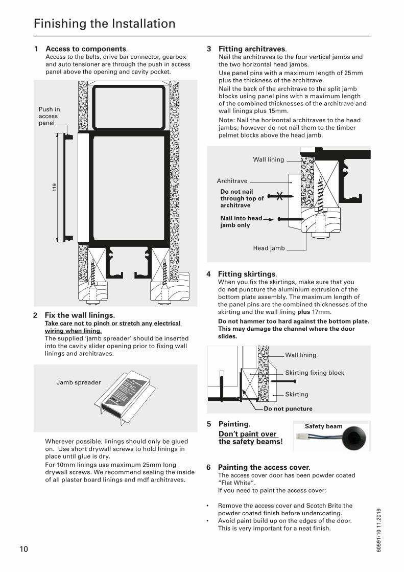
Jamb spreader
Finishing the Installation
119
1
19
Wall lining
Architrave
Head jamb
Nail into head jamb only
Do not nail through top of architrave
Safety beam
Push in access panel
3 Fitting architraves. Nail the architraves to the four vertical jambs and the two horizontal head jambs.
Use panel pins with a maximum length of 25mm plus the thickness of the architrave.
Nail the back of the architrave to the split jamb blocks using panel pins with a maximum length of the combined thicknesses of the architrave and wall linings plus 15mm.
Note: Nail the horizontal architraves to the head jambs; however do not nail them to the timber pelmet blocks above the head jamb.
4 Fitting skirtings. When you fix the skirtings, make sure that you do not puncture the aluminium extrusion of the bottom plate assembly. The maximum length of the panel pins are the combined thicknesses of the skirting and the wall lining plus 17mm.
Do not hammer too hard against the bottom plate. This may damage the channel where the door slides.
5 Painting. Don’t paint over
the safety beams!
6 Painting the access cover. The access cover door has been powder coated
“Flat White”. If you need to paint the access cover:
• Remove the access cover and Scotch Brite the powder coated finish before undercoating.
• Avoid paint build up on the edges of the door. This is very important for a neat finish.
Skirting
Wall lining
Do not puncture
Skirting fixing block
1 Access to components. Access to the belts, drive bar connector, gearbox and auto tensioner are through the push in access panel above the opening and cavity pocket.
2 Fix the wall linings. Take care not to pinch or stretch any electrical wiring when lining. The supplied ‘jamb spreader’ should be inserted into the cavity slider opening prior to fixing wall linings and architraves.
Wherever possible, linings should only be glued on. Use short drywall screws to hold linings in place until glue is dry.
For 10mm linings use maximum 25mm long drywall screws. We recommend sealing the inside of all plaster board linings and mdf architraves.

6059
1/11
11.
2019
11
Commissioning
1 Final commission and test. CS recommends using our commissioning service from one of our expert technicians.
Call for more information and a quote:
New Zealand: 0800 SLIDER (0800 754 337) Australia: 1800 573 486 International: +64 9 276 0800
Refer to the wiring diagram provided with the unit to ensure all cables are connected to the correct inputs and outputs.
Wire your chosen activation options to the appropriate cables that were run as indicated earlier in this document.
CAREFULLY ENSURE DOOR IS FREE FROM OBSTRUCTION AND IS MOVING FREELY BEFORE POWERING UP UNIT.
Power up the unit and test your activation options are functioning correctly.
Final mounting of activation options will now complete the installation.
1 Basic operation Operation of the AutoCav will vary depending
on customer requirements. Input functions can be selected from 32 options and outputs from 30 options.
Six inputs can be wired to the controller – eight if safety beams are not required.
Six outputs are offered – four transistor and two solid state relay.
2 Initial power up Upon power up the door will test the safety beams and ignore one or both pairs if they are deemed non operational. The door will not move until an input is received. When it receives an input it will perform the command at reduced speed for the first time. This is to test the end stops of the doorway. After the door has tested the extents of travel, preset speed will be achieved.
3 Safety beam blocked If door is closed no effect is seen.
If open, the door will remain open until the safety beam is clear.
If closing, the door will stop and open until safety beam is clear.
4 Obstacle in doorway When moving, the door will monitor parameters used to determine if an obstacle is present. Once an obstacle is detected the door will reverse direction to its end limit.
The door will move slowly past a previously detected obstacle to test the object has been removed. If the obstacle is present for five tests the door will remain fully open until given an input command.
5 Loss of power In the event that mains power to the AutoCav is lost, then one of two outcomes will apply:
A Battery backup will seamlessly power the door for up to 48 hours - dependant on battery charge/age.
B If no battery backup has been specified, the door will be able to be manually pushed in either direction with a force not greater than 110N.*
*Force subject to the following conditions: weight/size
of door, friction acting on door (seals etc.) and quality of installation/door.
Operation

6059
1/12
11.
2019
12
Bi-Parting
Single
Door leaf
Door leaf
Drive bar
Drive bar
2 x 90mm cap screws
2 x 90mm cap screws
Removal of Door and Belt
(If required at a later date for maintenance purposes)
Begin by removing the head jamb from one side (if fitted).
1 Removing the drive bar. Before removing the carriages you need to disconnect the drive bar from the socket on top of the door.
Follow the relevant instructions below.
Version 1: Remove the fastening clip from the door socket using a screwdriver, allowing the drive bar to be pulled forward and removed from the socket.
Version 2: Remove the belt connector bolt and T-nut from connector assembly, allowing the drive bar to be removed from the track.
Using a flat bladed screw driver, depress the tap marked “press” and lever upwards toward the track. Should the wedge be damaged in removal, contact your nearest CS branch for a replacement.
Once the locking wedge is removed, the drive bar will slide forward towards you and up out of the socket.
16mm ring spanner
Roll pin
To disconnect the drive bar from the belt, undo the cap screw whilst holding the T nut on the back. Once this is removed the drive bar will slide out.
2 Removing the belt. To release the tension on the belt for removal: Lift the roll pin to release the ratchet, allowing the pulley to move towards the gearbox.
Use a 16mm ring spanner to wind the bolt on the end until the pulley has moved along its slot fully.
Roll the belt off the pulley.
3 To re-tension the belt: Fit the belt over the pulleys at gearbox and tensioner ends, making sure that the belt to drive bar connector is located correctly. Undo the 16mm bolt. This will allow the pulley to slide back and tension the belt.
4 Removing the door leaf. Fit the club end of the adjusting spanner over the hexagonal nut at the bottom of the hanger pin.
Use the extended part of the spanner to press down the plunger pin that protrudes up from the mounting plate. Once this plunger is fully depressed, slide the spanner sideways towards the plunger pin.
The whole carriage (including the shaft) will now disengage from the mounting plate.
To lower door
To raise door
Adjusting spanner
Plunger pin
Club end of spanner

6059
1/13
11.
2019
13
Removal of Door and Belt
It is not always easy to slide the spanner sideways. You may need to relieve the door’s weight by putting a wedge between door and floor.
Closing jamb
Cavity Door leaf
Hook hole(aids removal)
T-guide
Unlocking clip
If you need to remove the T-guide: lift the unlocking clip and pull the black nylon T-guide forward. Use a hook to aid removal if required.
If you also want the carriages out: Slide them toward the notched end of the track and then take them out.
To replace the door or the carriages again: Follow the same steps, but in reversed order.
6059
1/14
11.
2019
14
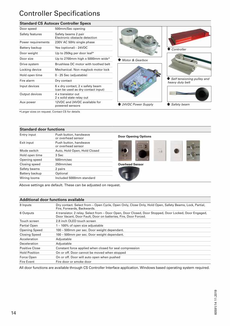
Standard CS Autocav Controller SpecsDoor speed 500mm/Sec opening
Safety features Safety beams 2 pairElectronic obstacle detection
Power requirements 230V AC 50Hz single phase
Battery backup Yes (optional) - 24VDC
Door weight Up to 250kg per door leaf*
Door size Up to 2700mm high x 5000mm wide*
Drive system Brushless DC motor with toothed belt
Locking device Mechanical. Non maglock motor lock
Hold open time 0 - 25 Sec (adjustable)
Fire alarm Dry contact
Input devices 6 x dry contact, 2 x safety beam (can be used as dry contact input)
Output devices 4 x transistor out2 x solid state relay out
Aux power 12VDC and 24VDC available for powered sensors
*Larger sizes on request. Contact CS for details
Standard door functionsEntry input Push button, handwave
or overhead sensor Door Opening Options
Exit input Push button, handwave or overhead sensor
Mode switch Auto, Hold Open, Hold ClosedHold open time 3 SecOpening speed 500mm/secClosing speed 250mm/sec Overhead SensorSafety beams 2 pairsBattery backup OptionalWiring looms Included 5000mm standard
Above settings are default. These can be adjusted on request.
Additional door functions available8 Inputs Dry contact. Select from – Open Cycle, Open Only, Close Only, Hold Open, Safety Beams, Lock, Partial,
Fire, Forwards, Backwards.6 Outputs 4 transistor. 2 relay. Select from – Door Open, Door Closed, Door Stopped, Door Locked, Door Engaged,
Door Vacant, Door Fault, Door on batteries, Fire, Door Forced.Touch screen 2.8 inch OLED touch screenPartial Open 1 – 100% of open size adjustableOpening Speed 100 – 500mm per sec. Door weight dependant.Closing Speed 100 – 500mm per sec. Door weight dependant.Acceleration AdjustableDeceleration AdjustablePositive Close Constant force applied when closed for seal compressionHold Position On or off. Door cannot be moved when stoppedForce Open On or off. Door will auto open when pushedFire Event Fire door or smoke door
All door functions are available through CS Controller Interface application. Windows based operating system required.
Controller Specifications
Motor & Gearbox
24VDC Power Supply Safety beam
Controller
Self tensioning pulley and heavy duty belt

6059
1/15
11.
2019
15
Servicing of the CS AutoCav should be carried out approximately every 5000 uses by a competent technician. As an example, doors used 30-40 times a day are moderate use (10000 - 15000 open cycles per year)Results should be recorded (see back page).A simple maintenance guide is given below. These checks should be integrated into a maintenance schedule.
Maintenance
Sample AutoCav Control Layout
Default Input Configuration
Latched input. Fire input allowed, all others ignored.
Latched input. Fire and Open Aux input allowed, all others ignored.
Momentary input. Open cycle, hold closed to keep door open.
Momentary input. Open cycle, hold closed to keep door open.
Momentary input. Open cycle, hold closed to keep door open.
Momentary input. Open door, hold closed to keep door open.
Safety beam, stops door from closing if active.
Safety beam, stops door from closing if active.
Door Leaf1 Check the carriages are running freely.
Wipe/clean the track if necessary.2 Check the door has floor clearance, and runs clear
of the floor guide.3 If door seals are fitted check for excessive wear. Door Controller1 Ensure cables are free from the moving drive bar
and belt.2 Ensure controller lid fits firmly.3 Check for loose plugs/terminals.
Door Motor1 Ensure the motor mounts are secure.2 Check for oil leaks.3 Ensure belt and pulley is in good condition.4 Check belt tension.
Door Operation1 Check safety devices are operational.2 Ensure the door and associated equipment are
functioning correctly.3 If batteries are connected an ‘on battery’ test should
be performed.4 Check the 24VDC power supply is free of dust and
has adequate air flow.

6059
1/16
11.
2019
16
INPUT 2
INPUT 3
S.B Emmitter 1 Screen
S.B Emitter 2 Screen
S.B Receiver 2 Screen
S.B Receiver 1 ScreenINPUT 8 0VDC
S.B Receiver 2+veINPUT 7
S.B Emmitter 1+ve
S.B Emitter +ve
+24/+12VDC125mA rated
INPUT 5
0VDC
0VDC
INPUT 4
+24/+12VDC125mA rated
+24 VDCPoly Fused 1Amp Total
OUTPUT 5Solid State Relay 1 Contacts
+12 VDCPoly Fused 1Amp Total
0VDC 0VDC
OUTPUT 6Solid Sate Relay 2 Contacts
OUTPUT 4 Isolated Digital
OUTPUT 3 Isolated Digital
OUTPUT 2 Isolated Digital
S.B Receiver 1+veINPUT 8
INPUT 1
INPUT 2 0VDC
INPUT 3 0VDC
INPUT 6INPUT 6 0VDC
OUTPUT 1 Isolated Digital
INPUT 1 0VDC
SMC Input Wiring
8
HEAT SINKS FOR SMC COMPONENTS
2 X 6mm2 FLEX SUPPLIED ON 100m ROLLS BY CS FOR DOORS
3-WAY MOLEX SNR PLUGMOTOR PHASE WIRES
MOTOR HALL EFFECT WIRESS
AUX OUTPUTS FROM SMCCONFIGURABLE VIA SMC VIEW
SAFETY BEAM INPUTS (2 SETS)
CLEAN CONTACT INPUTS 1 - 3CONFIGURABLE VIA SMC VIEW
POWERED DEVICE INUT4 CONFIGURABLE VIA SMC VIEW12VDC/24VDC MICRO JUMPER
POWERED DEVICE INUT5 CONFIGURABLE VIA SMC VIEW12VDC/24VDC MICRO JUMPER
20AMP BALDE FUSE REMOVABLE
USER INTERFACE INPUT RJ45 PIN 1 - PIN 1 WIRINGRS485 FULL DUPLEX
CANUS INTERFACE 1 RJ12
CANBUS INTERFACE 2 RJ12
PSU COMMS RJ11 PIN 1 - PIN 1 WIRING RS485 HALF DUPLEX
DIP SWITCHES FOR HARDWARE SETTINGSSEE TABLE
JUMPERS FOR POWERED DEVICE VOLTAGE SELECTION 12VDC/24VDC
2-WAY MOLEX SNR PLUG24VDC MAIN POWER
CLEAN CONTACT INPUTS 6CONFIGURABLE VIA SMC VIEW
RJ45 SERIAL COMMS POWER 5VDC/12VDCMICOR JUMPER SELECT
J-TAG PROGRAMMER HEADER
SPI-BUS HEADER PLUG INMODULE PCBJUMP PIN 12(Vol Sel) and 8 (Vcc)on Power up to reset to defaults as per DIP switch setting
LEDS TO INDICATE STATUS AS PER TABLE
DIP Switch Descriptons
RJ11 RS-485 Half Duplex
RJ45 RS-485 Full Duplex
RJ PLUG PIN ORDERVIEW FROM BOTTOM
1 2 3 4 5 6 7 8
LED Function Table
Dip Switch ON OFF1 CAN Open CAN Terminate2 Motor CW to Open Motor CCW to Open3 BN42-23 Motor BN42-33 Motor4 Default Settings 1 Default Settings 25 RJ11 RS485-PSU RJ11 RS485-SMC View6 SMC View Std SMC View + OLED
Pin Colour Label1 White/Orange Stripe CnVss2 White/Green Stripe Vcc 12/5VDC3 Whiote/Blue Strip RxB4 Blue Solid RxA5 White/Brown Stripe TxB6 Brown Solid TxA7 Green Solid GND8 Orange Solid Reset
Pin Colour Label1 Yellow NC2 Green Data B3 Red Data A4 Black 0VLED Colour LED ON LED OFF LED Flashing
1 Green 5VDC GOOD 5VDC Fault NA2 Red 24VDC GOOD 24VDC Fault NA3 Red 12VDC GOOD 12VDC Fault NA4 Green Safety Beam 2 Good Safety Beam 2 Distrupted Safety Beam 2 Good, Ignored5 Green Safety Beam 1 Good Safety Beam 1 Distrupted Safety Beam 1 Good, Ignored6 Green PC Comm Task Running PC Comm Task Crashed PC Comm Task Send/Receive7 Green Door Fault Normal Operation Door Trial Exired - Code required8 Red Door Open Door Not Open No Known Open Position9 Red Door Opening Door Not Opening Door Failed to Open 10 Red Door Closing Door Not Closing Door Failed to Close11 Red Door Closed Door Not Closed No Known Close Position
SMC Overview

6059
1/17
11.
2019
17
If you experience trouble with your AutoCav, please ask a qualified electrician to try the following solutions:
There is no power in the AutoCav controller (LED 1, LED 2 & LED 3 are OFF).• Check power outlet• Check power cable leads• Check power supply, power supply switch and fuse • Check power cable from UPS to controller
Door stays open and does not close
1. Safety beam is active (one of the LED 4 or LED 5 is OFF/both of the LEDs are OFF)
• Make sure the safety beams have not been blocked by something (e.g. paint, obstacle, tape)• Restart the controller*• Check the wiring according to the installation manual• Make sure Emitters are in one side and Receivers on the other side• Short out the safety inputs from the controller (Contact CS FOR DOORS for instruction of
safety beam short out)
2. One of the inputs stay active
• Activation Devices (e.g. push buttons, overhead sensor, PLC ) are faulty • Wrong wiring or damaged wires• Input 6 is ON. Input 6 is fire input and it is normally open.
One or more activation devices do not work• Wrong/ damaged wiring• Activation device is faulty• Key switch has been used to deactivate the other inputs (check wiring and schematic)
Door starts opening /closing but stops suddenly
Door opens and closes slowly • Swarf or dirt in the door’s track• Worn carriages• Any kind of obstacle in the door’s pocket, or somewhere that does not let the door move freely• To make sure door is running freely,
a) Unplug the power lead of the door’s controllerb) Open and close the door manuallyc) Door should run smoothly and freely
*To restart the controller, you need to turn off and turn on the controller. To do this, unplug the power lead of the controller and plug in again.
If the problems remain Please make sure you have done all the above steps, then install SMC Team Viewer software on your laptop.Connect your laptop to SMC controller, and call CS FOR DOORS technical support on 0800 754 337.Software is available from www.csfordoors.co.nz or the USB flash memory supplied with the unit.
Troubleshooting

6059
1/18
11.
2019
18
Components Checklist
AUTO COMPONENTS
CS Motor ZB00084
Dunker Motor ZB00118
Controller ZB00092
Tensioner ZB00310/11
Adapter Plate ZB00308
Drive Bar ZB00307
Belt Joiner ZB00318
Power Supply ZB00344
QTY QTY QTY QTY QTY QTY QTY QTY
ACTIVATION PACKS
ACPACK001 ACPACK002 ACPACK003 ACPACK004
QTY QTY QTY QTY
ACPACK005 ACPACK006 ACPACK008 CUSTOM
QTY QTY
QTY QTY
WIRING
6 Core Loom ZB00204
Safety Beams ZB00038
Power Cable ZB00206
RJ45 Cable ZB00102
SMC Cable ZB00096
Test Kit ZB00379
IEC Power
NZ US
QTY QTY QTY QTY QTY QTY QTY
WIRING DIAGRAM PROGRAMMING SMC DIP SWITCHES
QTY
QTY NO. DESCRIPTION ON OFF
1 CAN
2 Direction
3 Motor Type
4 Default Settings
5 RJ11
6 SMC
Technician: Date:
Job Name: SA:

6059
1/19
11.
2019
19
Maintenance Checklist
Date Checked
Door Leaf
1Check the carriages are running freely. Wipe/clean the track if necessary.
2Check the door has floor clearance, and runs clear of the floor guide.
3If door seals are fitted check for excessive wear.
Door Controller
1Ensure cables are free from the moving drive bar and belt.
2 Ensure controller lid fits firmly.
3 Check for loose plugs/terminals.
Door Motor
1 Ensure the motor mounts are secure.
2 Check for oil leaks.
3Ensure belt and pulley is in good condition.
4 Check belt tension.
Door Operation
1 Check safety devices are operational.
2Ensure the door and associated equipment are functioning correctly.
3If batteries are connected an ‘on battery’ test should be performed.
4Check the 24VDC power supply is free of dust and has adequate air flow.

6059
1/20
11.
2019
20
5 - 7 Rakino Way, Mt Wellington, Auckland, New Zealand
+64 9 276 0800 +64 9 276 2525 [email protected] www.csfordoors.co.nz
Auckland Head Office