Embed Size (px)
Citation preview

1

2

3

4

5
The SEL-700G Generator Protection Relay is the newest member of the SEL-700 series platform. It combines the protection features of the proven SEL-300G Generator Relay with the SEL-700 series platform features. Additionally, an automatic synchronizer function eliminates the need for standalone synchronizer equipment.

6
The SEL-700GT Intertie Protection Relay provides a complete intertie protection solution for distributed generation. With optional synchronous generator protection and synchronization, this relay provides complete generator and intertie protection in one compact and economical package.
The SEL-700GT provides IEEE 1547-compliant protection for any type of distributed generation, including gas turbine, diesel, methane recovery, wind, and photovoltaic.
Phase differential (87), compensator distance (21C), out-of-step (78), and 100 percent stator ground (64G) protection are not available with the SEL-700GT. Use the appropriate SEL-700G model for applications that require any of these protection elements.

7
The SEL-700GW Wind Generator Relay is a complete feeder protection solution for distributed generation. The SEL-700GW provides high system availability by using two sets of overcurrent elements (50/51) to detect and isolate a fault on either feeder. TheSEL-700GW also provides many of the functions of a programmable logic controller (PLC). Multiple communications options, a variety of I/O choices, and programmable SELOGIC® control equations make the SEL-700GW a complete solution.
8

9
ANSI device number functions included in the standard SEL-700G0 model include the following:
• Volts-per-hertz element (24)
• Undervoltage (27)
• Reverse/low forward power (32)
• Loss-of-field (40)
• Directional ground overcurrent (67G)
• Negative-sequence overcurrent (46)
• Thermal element (49T)
• Neutral overcurrent (50N/51N/51G)
• Phase overcurrent (50P)
• Voltage-controlled/voltage-restrained time-overcurrent (51C/51V)
• Overvoltage (59)
• Overfrequency and underfrequency elements (81)
• Restricted earth fault (REF)
• Ground differential element (87N)

10
Optional ANSI device number functions included in the SEL-700G include the following:
• Backup mho phase distance element (21)
• Synchronism check (25)
• 100 percent stator ground elements (64G)
• Out-of-step protection (78)
• Current differential elements (87)
• Second set of phase overcurrent (50P)

11
All SEL-700G models include IEEE C37.118-compliant synchrophasors for system state, response, and control capabilities.
Selected SEL-700G models have the built-in automatic synchronizer function, which provides output contact interfaces for the generator field voltage regulator and the prime mover speed control governor. Frequency, voltage, and phase control of the generator is automatically synchronized and connected to the power system with this function.
The thermal model provides protection from generator overheating due to excessive positive-and negative-sequence current draw. The thermal model is based on IEC 60255-8. If the RTD (resistance temperature detector) option is installed, the trip threshold can be biased for ambient temperature.
Four independent rate-of-change-of-frequency elements are provided with individual time delays for use when frequency changes occur (e.g., when there is a sudden imbalance between generation and load). These elements call for control action or switching action, such as network decoupling or load shedding. Each element includes logic to detect either increasing or decreasing frequency and above or below nominal frequency.
REF protection provides sensitive detection of internal ground faults on grounded wye-connected windings. The neutral current CT (current transformer) provides the operating current. Polarizing current is derived from the residual current calculated for the protected winding. A sensitive directional element determines whether the fault is internal or external.

12
The SEL-700G offers high-performance features in a package economical enough for small machine protection. Consider using this relay by itself to protect 1 to 5 MW machines.
In high-resistance grounded generator protection applications, the SEL-700G0+ can also provide 100 percent stator ground fault coverage if a neutral VT (voltage transformer, not shown) is included. (See the SEL-700G data sheet for complete model information.)
The left picture on this slide shows a diesel generator plant, while the right picture shows standby generators, both of which can be protected with the SEL-700G.
The one-line diagram represents the diesel generator application. There are multiple generators connected to the bus. The machine is a brush-type, salient pole rotor.

13
The SEL-700G1+ includes all of the protection functions of the proven SEL-300G, presently used to protect many of the world’s largest generators. (See the SEL-700G data sheet for complete model information.)
The one-line diagram shows a unit-connected generator. In addition to the functions available in the SEL-700G0, the SEL-700G1+ offers the following functions:
• Autosynchronizer
• Backup mho phase distance element (21C)
• Synchronism check (25)
• Synchronism check undervoltage (27S)
• RTD thermal elements (49RTD)
• Second set of phase overcurrent (50P)
• Synchronism check overvoltage (59S)
• 100 percent stator ground elements (64G)
• Out-of-step protection (78)
• Current differential elements (87)

14
The SEL-700G is a comprehensive, multifunction relay intended for primary and/or backup protection for any size synchronous machine.
Alternatively, the SEL-300G can be used as backup for applications that require a different hardware platform for primary and backup protection.

15
The combination of fundamental neutral overvoltage (59N) and third-harmonic voltage differential (V3d) provides 100 percent stator ground fault coverage. The two elements are treated as independent protection zones (64G1 and 64G2), each with its own settable definite-time delay.
Two important advantages of this method are the sensitivity and element overlap. The 59N element has good sensitivity for middle winding faults in the V3d element dead band. The V3d element detects low-winding faults that produce very little neutral fundamental voltage. Both elements detect faults in the upper area of the winding, providing two methods to detect more serious faults.

16

17
Each time a generator returns to service, it must synchronize to the power system before the interconnecting breaker can be closed. Synchronizing is the act of matching the magnitude and the frequency of the generator and system voltage and bringing the two voltages into phase alignment.
IEEE C50.12 and IEEE C50.13 provide the synchronizing limits for salient pole and round rotor machines. Closing the interconnection breaker outside these limits may cause electrical and mechanical transients that can exceed those transients experienced during three-phase short circuits.

18
Generator and transformer mechanical damage can be caused by excessive currents that circulate through the windings. Damage to the windings and core lamination is possible.
The prime mover and generator shafts are subjected to torsional stresses, possibly resulting in slippage of couplings, bearing misalignment, and fatigue damage to the shaft.
Power system disturbances are caused by the transients in active and reactive power.

19
Selected SEL-700G models (SEL-700G0+ and SEL-700G1+) have a built-in automatic synchronizer function, which provides output contact interfaces for the generator field voltage regulator and the prime mover speed control governor. With this function, frequency, voltage, and phase control of the generator are automatically synchronized and connected to the power system. These relays also provide generator start reports to record the automatic synchronizing event. The generator synchronization process can be viewed on a PC-based synchroscope with ACSELERATOR QuickSet® SEL-5030 Software.
You can specify the SEL-700G with a built-in generator synchronism-check function (25G). The synchronism-check function is extremely accurate and provides supervision for an acceptable voltage window and maximum percentage difference, maximum and minimum allowable slip frequency, target closing angle, and breaker closing delay.

20
The SEL-700G autosynchronizer matches the frequency, phase angle, and voltage of a generator to that of the bus before allowing the generator breaker to be closed.
In the example above, the SEL-700G monitors the generator frequency, phase angle, and voltage using the VAX, VBX, and VCX voltage inputs. (The SYNCPX setting determines the specific voltage input used.)
Generator mechanical speed and the associated electrical frequency and phase angle are adjusted by sending raise/lower pulses to the governor.
Generator voltage is adjusted by sending raise/lower pulses to the excitation system.
The width of the raise/lower pulses are proportional to the difference between the actual and target magnitudes. As the slip frequency and/or voltage get closer to the target value, the width of the raise/lower pulses gets shorter to prevent hunting. The raise/lower pulses stop when the magnitude is within an acceptable window.
When the synchronization conditions are satisfied (slip, voltage window, and voltage difference), the SEL-700G initiates a close, compensating for the present slip and breaker closing time.

21
ACSELERATOR QuickSet software provides a synchroscope display when connected to an SEL-700G. The synchroscope display emulates the familiar look of an electromechanical synchroscope device. This allows the observer to monitor the autosynchronization process.

22
The SEL-700G with automatic synchronizer function generates a generator synchronism report with all the relevant analog and digital signals to facilitate quick event analysis. The sample rate can be selected from 0.25, 1, and 5 cycles. The report captures 4,800 time-stamped data points.
23

24
The IEEE 1547 standard is applicable to all distributed resource technologies with aggregate capacity of 10 MVA or less, interconnected to the electrical power system at primary or secondary distribution voltages. The standard focuses on radial primary or secondary distribution systems.
The standard has been widely adopted in the United States, with a few exceptions in California, New York, and Texas.
In 2008, IEEE 1547.2 was approved. It provides technical background and application details to support understanding of IEEE 1547-2003.

25
The SEL-700GT provides an IEEE 1547-2003-compliant solution to protect both the electric utility grid and distributed generation equipment. With the SEL-700GT, all IEEE 1547 requirements are met, including the following:
• Voltage-based protection
• Unintentional islanding protection
• Current-based protection with directional overcurrent
• Out-of-phase reclosing protection

26
The ―plus‖ option adds synchronous generator protection and autosynchronization to
provide complete generator and intertie protection in one compact and economical package. The SEL-700GT+ does the work of the following three devices:
• Interconnection relay
• Generator relay
• Autosynchronizer

27
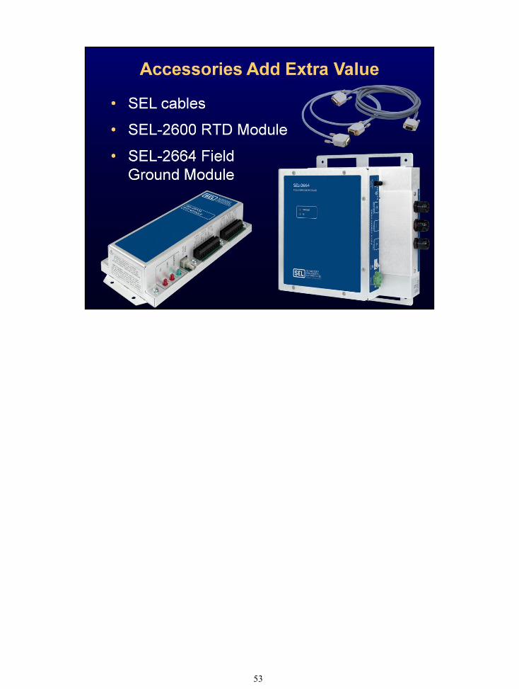
Combining the SEL-700G with the SEL-2664 Field Ground Module offers the following features for field ground detection:
• Comprehensive generator protection in the SEL-700G.
• Sensitive, early detection of field ground faults.
• Easy installation with no settings in the SEL-2664.
• Noise-free electrical isolation through fiber-optic communication.
Key benefits of the SEL-2664 include the following:
• Operates on most large or small generators.
• Configures to trip, warn, or simply monitor field ground resistance to match customer needs.
• Includes high-quality construction and the widest operating temperature range in the industry (–40° to +85°C).
• Accurately detects field grounds, whether the generator is de-energized, stopped, or operating. The SEL-2664 has best-in-class accuracy of 5 percent or 500 ohms.
The SEL-2664 has three mounting options: wall, panel, and rack. The rack mount includes an adapter plate and panel-mount unit.

28
The basic function of a synchronous machine rotor is to produce the rotating magnetic field necessary to induce voltage in the stator windings. The source for this magnetic field is the dc current that circulates through the field winding.
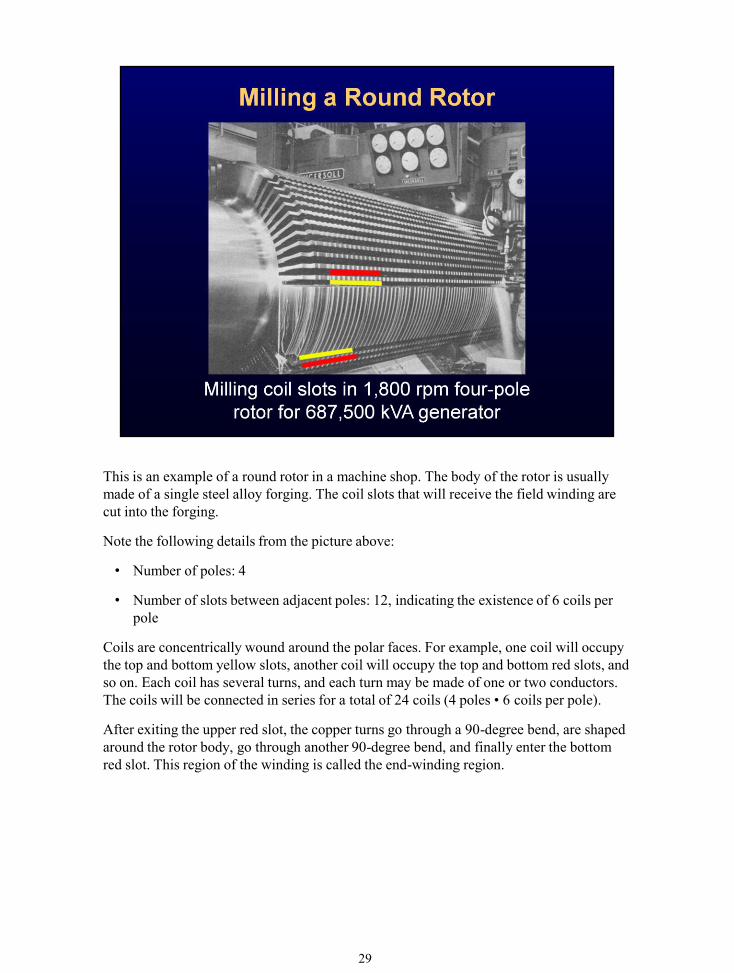
Synchronous machine rotors are divided into two groups: round rotors and salient pole rotors. Round rotors are found in machines with high nominal speeds (1,800 to 3,600 rpm at 60 Hz), while salient pole rotors are common to machines with lower speeds (1,200 rpm and below at 60 Hz). There are some specific applications in which salient pole rotors are required to operate at 1,800 rpm (four-pole machines at 60 Hz).
29
This is an example of a round rotor in a machine shop. The body of the rotor is usually made of a single steel alloy forging. The coil slots that will receive the field winding are cut into the forging.
Note the following details from the picture above:
• Number of poles: 4
• Number of slots between adjacent poles: 12, indicating the existence of 6 coils per pole
Coils are concentrically wound around the polar faces. For example, one coil will occupy the top and bottom yellow slots, another coil will occupy the top and bottom red slots, and so on. Each coil has several turns, and each turn may be made of one or two conductors. The coils will be connected in series for a total of 24 coils (4 poles • 6 coils per pole).
After exiting the upper red slot, the copper turns go through a 90-degree bend, are shaped around the rotor body, go through another 90-degree bend, and finally enter the bottom red slot. This region of the winding is called the end-winding region.

30
In the scheme shown above, a voltage square wave is injected onto the field, and the resulting current leakage to ground is measured. This measurement is used to estimate the ground resistance. If this calculated ground fault resistance is outside the predetermined normal range, then an alarm and/or trip is generated.
Switched dc voltage injection is superior compared to the other methods because of the following:
• The voltage divider method requires the generator field to be excited—measurement is difficult at or around null point.
• Both ac and dc injections have long-term corrosion problems because of leakage paths via bearings to ground, etc.
• Switched bipolar dc injection is at a very low frequency of 0.25 or 1 Hz. This low-frequency signal overcomes field-to-ground capacitance without inducing corrosion.

31
A square wave with positive and negative magnitudes, Voscp and Voscn, is applied to the field winding circuit.
Referring to the drawing on the previous slide, Rx is the rotor ground fault resistance, and Cfg is the capacitance from the field winding and ground.
If there is no connection between the rotor and the ground (Rx equals infinity), no direct current will flow in the loop in the steady state, and the voltage across the sense resistor (Rs) will be zero. If there is a fault with resistance Rx, a current will flow in the loop, and a significant voltage will develop on the resistance Rx. Fault resistance Rx can then be calculated as a function of the voltage drop across resistor Rs.

32
SEL-700G rear serial ports include the following:
• Port 2: multimode (ST®) fiber-optic serial port
• Port 3: EIA-232
• Port 4: optional Slot C serial communications card (SELECT EIA-232/485)
If the application requires inputs from the SEL-2600 RTD Module, an SEL-2664, and an SEL communications processor, SEL recommends connecting the SEL-2600 to the fiber-optic serial Port 2. Connect the SEL-2664 using an SEL-2812MR Fiber-Optic Transceiver to the EIA-232 Port 3, and connect the SEL communications processor using the EIA-232 Port 4.
33
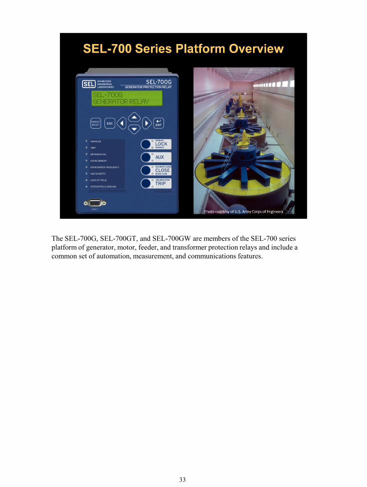
The SEL-700G, SEL-700GT, and SEL-700GW are members of the SEL-700 series platform of generator, motor, feeder, and transformer protection relays and include a common set of automation, measurement, and communications features.

34
The SEL-700G provides another product in the popular SEL-700 series product line. These relays are designed and tested to the same rigorous standards as the SEL-300 and SEL-400 series relays.

35
MIRRORED BITS® communications technology provides bidirectional relay-to-relay digital communications. MIRRORED BITS communications can operate independently on up to two EIA-232 rear serial ports and one fiber-optic rear serial port on a single SEL-700G. Use MIRRORED BITS communications to transmit and receive information between the SEL-700G and other relays within the power plant to enhance coordination.
In addition to comprehensive protection functions, the SEL-700G offers many features that add value, including the following:
• Comprehensive metering. Fundamental metering is provided for all currents, voltages, frequency, and calculated power quantities. Root-mean-square (rms) metering is provided for phase currents and voltages. Harmonic metering provides magnitude of current harmonics.
• Breaker-wear monitoring.
• Comprehensive reporting, including oscillography, load profiling, and SER (Sequential Events Recorder) reports.
• ACSELERATOR QuickSet software.

36
Customize the SEL-700G to suit your particular protection and control applications. SELECT I/O option cards include digital (contact) inputs and outputs, analog inputs and outputs, and RTD inputs.
Communications card options are described on the previous slide.
The SELECT I/O options can be ordered in new relays or installed in existing relays in the field.

37

38
Power supply options include:
• 24-48 Vdc
• 110-250 Vdc
• 110-230 Vdc
Multiple protocols are available on the Ethernet port(s): Modbus® TCP, Telnet, and FTP, with optional IEC 61850 and DNP3 LAN/WAN (local-area network/wide-area network).
The green Connectorized® terminals offer the advantage of robust connections while minimizing installation and replacement time. Installing or removing the Connectorized terminals takes only a few minutes. All wiring remains connected to the terminal block. Connectorized terminals accept wire size 12 to 24 AWG.
The voltage and current inputs use conventional screw-terminal blocks. Ring terminals are recommended for current inputs.

39

40
The SEL-700G uses a 200 MHz ColdFire® microcontroller for the main processor. Removing heat from the very capable and fast microprocessor was a challenge that SEL answered with an SEL-patented, heat-sink design. The product is rated to +85°C (+185°F).
The SEL-700G samples analog input waveforms at 32 samples per cycle and processes relay and protection logic at 4 samples per cycle.
SEL tests the SEL-700G to rigorous industry compliance standards, including the following:
• CSA C22.2
• IEC/EN 61010 (CE Mark)
• UL File Number E320062, Class I, Zone 2 Hazardous Location approved

41
Use the front panel to monitor power system data, view fault indications and event information, set the relay, and operate local control.
There are eight LEDs (light-emitting diodes) that provide information on relay self-test and fault types. Six of the LEDs are programmable and have a slide-in card for changing labels.
Seven navigation pushbuttons perform a variety of functions. These functions include changing relay settings, observing metered data, viewing event report summaries, checking relay internal status, exercising contact outputs for testing, and resetting targets. The pushbuttons allow easy maneuvering among menus displayed on the 2 x 16 character backlit LCD (liquid crystal display).
Four programmable pushbuttons provide user inputs for control action. Start and stop functions are provided in the default settings, but any button action can be programmed. The pushbuttons also have eight independent LEDs to provide programmable indication for I/O, logic, or group settings.

42

43
The SEL-700G provides comprehensive metering. Fundamental metering is provided for all currents, voltages, frequency, and calculated power quantities. RMS metering is provided for phase currents and voltages.
Refer to the SEL-700G instruction manual for details on all of the metering available in the SEL-700G.

44
Gain added value provided by event reports, SER, monitoring, and metering functions. Reduce operating costs with extensive reporting, metering, and monitoring of operational and protection events.
Gain an unmatched view of performance during critical events with the SEL-700G comprehensive reporting, which includes the following features:
• The load profile feature allows you to select up to 17 from the approximately 180 available analog quantities. Sample at 5-, 10-, 15-, 30-, or 60-minute intervals. Over 4,000 time samples are stored in nonvolatile memory.
• Raw or filtered event reports (32 samples per cycle or 4 samples per cycle) allow you to select from 180-, 64-, or 15-cycle event reports stored in nonvolatile memory.
• Up to 1,024 most recent entries are stored in the SER.
45
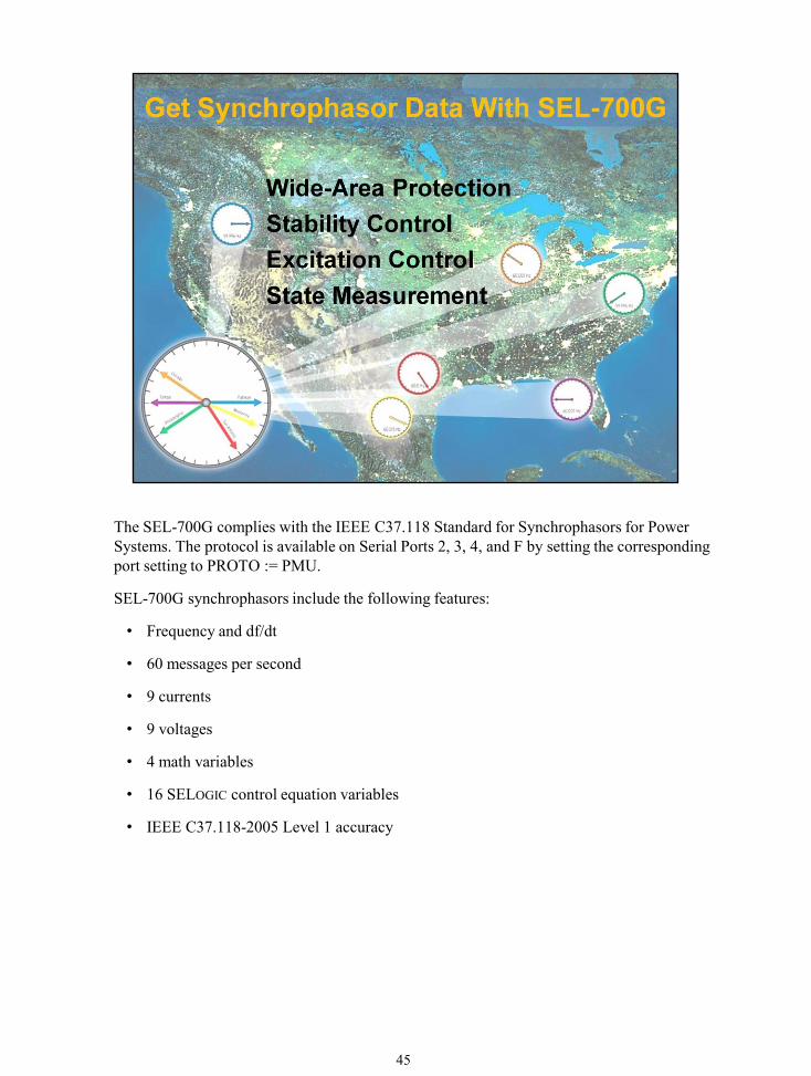
The SEL-700G complies with the IEEE C37.118 Standard for Synchrophasors for Power Systems. The protocol is available on Serial Ports 2, 3, 4, and F by setting the corresponding port setting to PROTO := PMU.
SEL-700G synchrophasors include the following features:
• Frequency and df/dt
• 60 messages per second
• 9 currents
• 9 voltages
• 4 math variables
• 16 SELOGIC control equation variables
• IEEE C37.118-2005 Level 1 accuracy

46

47
The SEL-700G contains a comprehensive set of 32 SELOGIC control equations, local and remote control bits, and counters.

48
SELOGIC control equations add great flexibility to the SEL-700G to create specialized logic for control or protection. Enhanced SELOGIC control equations use Relay Word bit names to create Boolean logic equations. The equations accept several logical operators for combining Relay Word bit names. These operators are shown on the slide. Using Relay Word bits, the equations can take on a great degree of complexity when applications require these capabilities. The output of each equation is a logical 1 (true) or logical 0 (false), depending on the logic state of each Relay Word bit and the relationship of these bits as defined by the operators.
Many settings in the SEL-700G are in the form of SELOGIC control equations. The factory-set default values can be modified to support specialized protection and automation functions.

49

50
The relay chassis contains three expansion slots (C, D, and E) for adding the option cards. Add the following communications options:
• Ethernet (10/100BASE-T copper, 100BASE-FX fiber)
– IEC 61850 – Modbus TCP
– DNP3 LAN/WAN – Telnet and FTP
• Serial
– MIRRORED BITS communications – Modbus RTU (multisession)
– DNP3 serial – SEL ASCII
– EIA-485 port – EIA-232 port
• DeviceNet™ communications card
Extensive communications and software capabilities are possible. Communicate seamlessly with built-in SEL ASCII, MIRRORED BITS communications, Event Messenger, IEEE C37.118 protocol (synchrophasor data), Modbus RTU, and optional Ethernet with IEC 61850, Modbus TCP, DNP3 serial or LAN/WAN, and DeviceNet protocols. Quickly and easily set the SEL-700G with the included ACSELERATOR QuickSet software.
Concurrent Ethernet sessions include: (2) Telnet, (2) FTP, (6) IEC 61850, (3) DNP3, and (2) Modbus.

51

52
Gain even more value from the SEL-700G via convenient product accessories.
53

54
The SEL-700G operates over a –40° to +85°C (–40° to +185°F temperature range and features a worldwide, ten-year product warranty. As an ISO 9001:2008-certified company, SEL builds in reliability by using superior design processes.

55