Embed Size (px)
Citation preview
CIG
RE-
UK
Sprin
g C
onfe
renc
e an
d Te
chni
cal V
isit
14-1
5 M
arch
201
2.
Francisco M. Gonzalez-Longatt, www.fglongatt.org.ve 1
Implications of the DC Voltage Control Strategy on the Dynamic Behavior of Multi-terminal HVDC following a Converter Outage
F. Gonzalez-Longatt1,2, J. Roldan3
M. Burgos-Payán3, V. Terzija4
1 Coventry University2 Venezuelan Wind Energy Association
3 Universidad de Sevilla4 The University of Manchester

CIG
RE-
UK
Sprin
g C
onfe
renc
e an
d Te
chni
cal V
isit
14-1
5 M
arch
201
2.
Francisco M. Gonzalez-Longatt, www.fglongatt.org.ve 2
I. OutlineI. IntroductionII. Control Strategies for MTDC Networks Operation
(i) Inner-Fast Current Controller, (ii) DC Voltage Controller, (iii) AC Voltage Controller, (iv) Active Power Controller, (v) Reactive Power Controller.
III. DC Voltage Control: Methods(i) Direct Voltage-Droop Method (ii) Voltage-Margin Method
IV. Simulations and Results(i) Case I: Sudden load increase, (ii) Case II: One Converter Outage
V. Conclusions

CIG
RE-
UK
Sprin
g C
onfe
renc
e an
d Te
chni
cal V
isit
14-1
5 M
arch
201
2.
Francisco M. Gonzalez-Longatt, www.fglongatt.org.ve 3
I. Introduction (1/2)• The EU and the G8 Heads of
Government committed their countries in 2009 to an 80 % reduction in Green House Gas emissions by 2050.
• International consensus to reach this target requires the EU to achieve a 'nearly zero-carbon power supply‘.
• Supergrid is the name of this future electricity system that will enable Europe to undertake a once-off transition to sustainability.
• Multi-terminal HVDC (MTDC) using Voltage Source Converter (VSC) is the most appropriate technology to enable the concept of Supergrid.

CIG
RE-
UK
Sprin
g C
onfe
renc
e an
d Te
chni
cal V
isit
14-1
5 M
arch
201
2.
Francisco M. Gonzalez-Longatt, www.fglongatt.org.ve 4
I. Introduction (2/2)• The power injections (Pi) in a DC grid
are controlled by the converters. • On a MTDC grid as Supergrid, the
power flow into, or out of, each converter can be dynamically changed without any reconfiguration of the HVDC grid.
• Although Supergrid should allow the full control of active power on all converters, several control challenges arise from this condition.
• The purpose of this paper is to analyze the potential implications of the DC Voltage Control Strategy on the dynamic behavior of Multi-terminal HVDC following a Converter Outage.
Scot
land
Sho
re
Lin
e (5
GW
)E
ngla
nd S
hore
Lin
e(2
4GW
)
Nor
Ned
2
Nor
Ned
(7G
Q In
terf
ace
Cap
acity
)
Den
mar
k Sh
ore
Lin
e (3
.5G
W)

CIG
RE-
UK
Sprin
g C
onfe
renc
e an
d Te
chni
cal V
isit
14-1
5 M
arch
201
2.
Francisco M. Gonzalez-Longatt, www.fglongatt.org.ve 5
II. Control Strategies for MTDC (1/3) Schematic representation of MTDC control system
hierarchy The master control optimizes the overall performance of the MTDC by regulating the DC side voltage. It is provided with the minimum set of functions necessary for coordinated operation of the terminals in the DC circuit, i.e. start and stop, minimization of losses, oscillation dampingand power flow reversal, black start, AC frequency and AC voltage support.
The terminal controllers determine the behavior of the converter at the system bus.
They are designed for the main functions for controlling: active power (P), reactive power (Q), AC and the DC voltage (Vac, Udc)
Time Scale
VSCdcn
iP ,dc iP
,dc iUiV
,g iP,l iP
1gP
1lP

CIG
RE-
UK
Sprin
g C
onfe
renc
e an
d Te
chni
cal V
isit
14-1
5 M
arch
201
2.
Francisco M. Gonzalez-Longatt, www.fglongatt.org.ve 6
II. Control Strategies for MTDC (2/3)
Terminal Controllers are based on locals actions and measurements.Wide-area measurement and control can improve the system performance.
refQQ
acV,ac refV
*qi
*di
refPP
dcU,dc refU
,ac CtrlVCtrlQ
,dc CtrlUCtrlPTerminal Controller

CIG
RE-
UK
Sprin
g C
onfe
renc
e an
d Te
chni
cal V
isit
14-1
5 M
arch
201
2.
Francisco M. Gonzalez-Longatt, www.fglongatt.org.ve 7
II. Control Strategies for MTDC (3/3)
refQQ
acV,ac refV
*qi
*di
refPP
dcU,dc refU
,ac CtrlVCtrlQ
,dc CtrlUCtrlP
refQ
Q,
,i Q
p Q
KK
s *
qi
maxi
maxi
,,
i Udcp Udc
KK
s *
di
maxi
maxi,dc refU
dcU acV
,ac refV ,,
i Vacp Vac
KK
s *
qi
maxi
maxi
refP
P,
,i P
p P
KK
s *
di
maxi
maxi
*dv
*qv
,d refi
,q refi
di
qi
dv
qv
,,
i idp id
KK
s
,,
i iqp iq
KK
s
LL
Q Controller P Controller
Udc ControllerVac Controller
Idq Controller
Terminal Controller

CIG
RE-
UK
Sprin
g C
onfe
renc
e an
d Te
chni
cal V
isit
14-1
5 M
arch
201
2.
Francisco M. Gonzalez-Longatt, www.fglongatt.org.ve 8
III. DC VOLTAGE CONTROL
When the active power is to be transmitted from Terminal B to Terminal A (PA<0, PB>0), the voltage margin (Udc) is subtracted from the DC reference voltage for Terminal A.
(i) Voltage Margin Method (VMM) (ii) Voltage-Droop Method (VDM)
When Udc drops the slack converter station (VSCA) will increase the active power injection in the DC grid PA until a new equilibrium point.
,AdcU
AP
dcU
upperPlowerP
,AdcU
AP
Slope mcdcU
Initial operating pointInverter
Lower limitRectifier
“a”
Upper limit
upperPlowerP
,adc refU
“b”
brefP
brefU
arefP

CIG
RE-
UK
Sprin
g C
onfe
renc
e an
d Te
chni
cal V
isit
14-1
5 M
arch
201
2.
Francisco M. Gonzalez-Longatt, www.fglongatt.org.ve 9
IV. Simulations and Results (1/2)• The dynamic behavior of AC/DC Test System is analyzed based
on time-domain simulations. DigSILENT PowerFactoryTM
v14.0.525.1.
• Case I: The effect of sudden load increases on power flows and transient response in the AC/DC Test System.
• Case II: The effects of a converter outage on the dynamic response are also analyzed.
AC Test System: of Stagg and El-Abiad. DC Test System: VSC MTDC system.

CIG
RE-
UK
Sprin
g C
onfe
renc
e an
d Te
chni
cal V
isit
14-1
5 M
arch
201
2.
Francisco M. Gonzalez-Longatt, www.fglongatt.org.ve 10
IV. Simulations and Results (2/2)• An sequential solution algorithm is used for the AC/DC
power flow solution.
• That solution is used as initial conditions for the dynamic simluations.
fglongatt
PowerFactory 14.0.525
Stagg and El-Abiad Test System
DC Voltage Control on Multi-Terminal HVDC Juan Manuel Roldan
Francisco M. Gonzalez-Longatt, PhD
Project: fglongatt Graphic: AC Power Networ Date: 01/01/2012 Annex:
ElmSouth
NorthLake Main
Bus 598.940.99-4.20
Bus 499.200.99-4.31
Bus 399.501.00-3.94
Bus 2100.001.00-2.44
Bus 1106.001.060.00
20/10
20.0010.00
G~G2
40.00-106.69113.94
External Grid
135.98..85.82 ..0.85
2-5
25.62-0.8325.64
2-5
-25.36-1.3525.64
45
-0.36-1.263.70
45
0.36-3.653.70
2-4
-17.43-0.2617.88
2-4
17.62-3.1517.88
3-4
22.261.6622.64
3-4
-22.21-3.4822.64
2-3
13.90-3.6914.37
2-3
-13.780.0614.37
1-3
36.0814.8938.87
1-3
-34.93-16.7338.87
1-2
99.9070.93119.03
1-2
-97.14-69.02119.03
60/40
60.0010.00
40/5
40.005.00
45/15
45.0015.00
DIg
SILE
NT
fglongatt
PowerFactory 14.0.525
VSC Multi-Terminal HVDC System
DC Voltage Control Dynamic Case
Francisco M. Gonzalez-Longatt, PhD
Project: Graphic: DC Power Netwo Date: 01/01/2012 Annex:
RECTIFIER INVERTER
INVERTER
Multi-Terminal HVDC System
Bus 598.940.99-4.20
Bus 399.501.00-3.94
Bus 2100.001.00-2.44
Bus 8148.240.990.00
Bus 7149.701.000.00
Bus 6154.221.030.00
35.005.00
18.550.00
-60.0040.00
VSC 37
18.550.00
VSC 37
-19.620.00
VSC 58
35.005.00
VSC 58
-36.230.00
VSC 26
-60.0040.00
VSC 26
57.900.00
6-7
-28.940.0029.00
6-7
29.820.0029.00
6-8
28.090.0027.32
6-8
-27.000.0027.32
7-8
-9.240.004.67
7-8
9.330.004.67
DIg
SILE
NT

CIG
RE-
UK
Sprin
g C
onfe
renc
e an
d Te
chni
cal V
isit
14-1
5 M
arch
201
2.
Francisco M. Gonzalez-Longatt, www.fglongatt.org.ve 11
Models on DSL
FRAME P-Q Controller: Active and Reactive Power Controller (P-Q Mode)
Frame: P-Q ModeDeveloped by: Juan M. Roldan
Francisco M. Gonzalez-Longatt, PhD01/01/2012
P controllerElmDsl*Pref
0
1
2Current Controller
ElmDsl*
0
1
2
3
0
1
PLL measureElmPhi*
0
1
2
P-Q measStaPqmea*
0
1
VSCElmVscmono*
0
1
2
3
0
1
Control fElmDsl*
fref 0
1
Q controllerElmDsl*Qref
0
1
FRAME P-Q Controller: Active and Reactive Power Controller (P-Q Mode)
iq(1)
iqref
idrefDPf
id(1)
Q
Fmeas
P
sinrefcosref
Pmq
Pmd
DIg
SILE
NT
FRAME Control Udc-Q: Controller Udc-Q
FRAME Udc-Q ModeDeveloped by: Juan M. Roldan
Francisco M. Gonzalez-Longatt, PhD01/01/2012
VSC-1ElmVscmono*
0
1
2
3
0
1Vdc ControlElmVdc*
Vdc_ref
0
1
2
3
Current C..ElmDsl*
0
1
2
3
0
1
Idc measStaImea*
Vdc measStaVmea*
P-Q measStaPqmea* Q control
ElmDsl*Qref
0
1
Vac measStaVmea*0
1
transformation phase ..ElmDsl* iq
0
1
2
3
0
1
PLLElmPhi*
0
1
FRAME Control Udc-Q: Controller Udc-Qud
iqid
idref
iqref
Pmq
PmdIdc
Vdc
Q
uiur
cosref
sinref
DIg
SILE
NT
idq controller: Current Controller, Internal-Fast Loop
Developed by: Juan M. Roldan and F. Gonzalez-Longatt, PhDProject: Multi-Terminal HVDC
Date: 01/01/[email protected]
-
Pmdq limiter
Max
0
1
0
1
-
Current Limit..
Max_I
0
1
0
1
{K (1+1/sT)}K,T
Max_Pm
Min_Pm
{K (1+1/sT)}K,T
Max_Pm
Min_Pm
idq controller: Current Controller, Internal-Fast Loop
0
1
2
3
0
1Pmq
Pmd
iql
idl
iqref
idref
uq
ud
diq
did
iq
id
DIg
SILE
NT
CIG
RE-
UK
Sprin
g C
onfe
renc
e an
d Te
chni
cal V
isit
14-1
5 M
arch
201
2.
Francisco M. Gonzalez-Longatt, www.fglongatt.org.ve 12
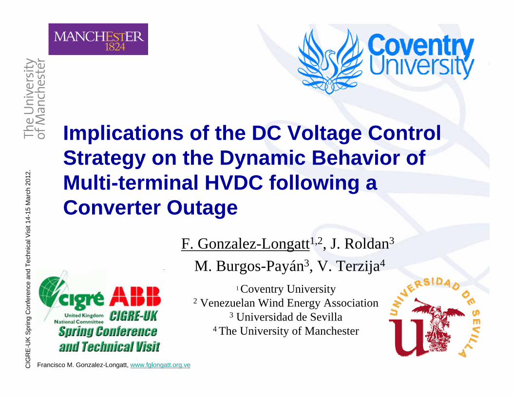
DC Voltage Controllers: DSL ModelsUdc-P droop controller: Udc Droop Controller
Droop
Udc-P Droop Controller Developed by: Juan M. Roldan
Francisco M. Gonzalez-Longatt, PhDProject: Multi-Terminal HVDC
01/01/2012, [email protected]
- {K (1+1/sT)}Kp,Tp
Max_I
Min_IKKv
Limiter with input si..
-
Udc-P droop controller: Udc Droop Controller
2
1
4
3
0
5I_min
I_max
Idrefu
Pref
P dP
Plower
KDV
DV
Pmax
Udc
Udcref
DIg
SILE
NT
Udc Controller: Voltage-Margin Method (VMM)
Udc-P Voltage-Margin Method Developed by: Juan M. Roldan
Francisco M. Gonzalez-Longatt, PhDProject: Multi-Terminal HVDC
01/01/2012, [email protected]
Constant1/mc
{K (1+1/sT)}Ku,Tu
Max_I
Min_I
Limiter with input signals-
Udc Controller: Voltage-Margin Method (VMM)
2
1
0
5
3
4
I_max
I_min
o11u1
Ud
Idc
o1du
Pupper
Plower
IdrefU
Udc_ref
Udc
o12
DIg
SILE
NT
,
,i Udc
p Udc
KK
s di
maxi
maxi,dc refU
dcU1
cm
refP
P

CIG
RE-
UK
Sprin
g C
onfe
renc
e an
d Te
chni
cal V
isit
14-1
5 M
arch
201
2.
Francisco M. Gonzalez-Longatt, www.fglongatt.org.ve 13
Case I: Sudden Load Increase (1/2)
0 0.1 0.2 0.3 0.4 0.5 0.6 0.729
30
31
32
Time (s)
Pow
er 6
-7 (M
W)
MarginDroop ADroop B
0 0.1 0.2 0.3 0.4 0.5 0.6 0.727.5
28
28.5
29
Time (s)
Pow
er 6
-8 (M
W)
MarginDroop ADroop B
0 0.1 0.2 0.3 0.4 0.5 0.6 0.76
7
8
9
10
11
Time (s)
Pow
er 7
-8 (M
W)
MarginDroop ADroop B
RECTIFIER INVERTER
INVERTER
Multi-Terminal HVDC System
Bus 598.940.99-4.20
Bus 399.501.00-3.94
Bus 2100.001.00-2.44
Bus 8148.240.990.00
Bus 7149.701.000.00
Bus 6154.221.030.00
35.005.00
18.550.00
-60.0040.00
VSC 37
18.550.00
VSC 37
-19.620.00
VSC 58
35.005.00
VSC 58
-36.230.00
VSC 26
-60.0040.00
VSC 26
57.900.00
6-7
-28.940.0029.00
6-7
29.820.0029.00
6-8
28.090.0027.32
6-8
-27.000.0027.32
7-8
-9.240.004.67
7-8
9.330.004.67
Sudden Load Increase
Voltage margin method produces the smallest stress on AC system.
Voltage-Droop method increases power transfer during initial response.
40P MW

CIG
RE-
UK
Sprin
g C
onfe
renc
e an
d Te
chni
cal V
isit
14-1
5 M
arch
201
2.
Francisco M. Gonzalez-Longatt, www.fglongatt.org.ve 14
Case I: Sudden Load Increase (2/2)• The blue line shows the bus voltage’s
response with only one voltage controller operating, voltage margin method.
• The red line represents the dynamic response when a voltage droop controller (mc = -0.1) is operating on converter station VSC26.
• The transient over-voltages and under-voltages are reduced as expected using the droop control.
• The slopes of the voltage-droop controller considered in this simulation are 1/mc= -10.0, -8.0, -2.0 p.u. for converters VSC26, VSC37, VSC58 respectively.
0 0.2 0.4 0.6 0.8 11
1.01
1.02
1.03
1.04
Time (s)
Bus V
olta
ge (p
.u)
0.1 0.15 0.2
1.01
1.02
1.03
MarginDrop
0 0.2 0.4 0.6 0.8 10.97
0.975
0.98
0.985
0.99
Time (s)
Bus V
olta
ge (p
.u)
0.05 0.1 0.15
0.97
0.975
0.98
0.985
0.99MarginDroop
Bus 5, AC voltage transient with margin and droop control strategies
Bus 6, DC voltage transient with margin and droop control strategies

CIG
RE-
UK
Sprin
g C
onfe
renc
e an
d Te
chni
cal V
isit
14-1
5 M
arch
201
2.
Francisco M. Gonzalez-Longatt, www.fglongatt.org.ve 15
Case II: Converter Outage (1/2)
RECTIFIER INVERTER
INVERTER
Multi-Terminal HVDC System
Bus 598.940.99-4.20
Bus 399.501.00-3.94
Bus 2100.001.00-2.44
Bus 8148.240.990.00
Bus 7149.701.000.00
Bus 6154.221.030.00
35.005.00
18.550.00
-60.0040.00
VSC 37
18.550.00
VSC 37
-19.620.00
VSC 58
35.005.00
VSC 58
-36.230.00
VSC 26
-60.0040.00
VSC 26
57.900.00
6-7
-28.940.0029.00
6-7
29.820.0029.00
6-8
28.090.0027.32
6-8
-27.000.0027.32
7-8
-9.240.004.67
7-8
9.330.004.67
Outage
X36.23P MW
0 0.1 0.2 0.3 0.4 0.5 0.6 0.725
30
35
40
45
Time (s)
Pow
er 6
-7 (M
W)
MarginDroop ADroop B
0 0.1 0.2 0.3 0.4 0.5 0.6 0.7-20
-10
0
10
Time (s)
Pow
er 7
-8 (M
W)
MarginDroop ADroop B
0 0.1 0.2 0.3 0.4 0.5 0.6 0.710
15
20
25
30
Time (s)Po
wer
6-8
(MW
)
MarginDroop ADroop B
Reverse power FlowConverter outage can create reverse power flows, overload on undersea cables and converter stations is a real possibility.Voltage-Droop method performs better.

CIG
RE-
UK
Sprin
g C
onfe
renc
e an
d Te
chni
cal V
isit
14-1
5 M
arch
201
2.
Francisco M. Gonzalez-Longatt, www.fglongatt.org.ve 16
Case II: Converter Outage (2/2)• This simulation results are used to
investigate the effect of a distributed voltage droop control on bus 2 (VSC26).
• The response of bus voltage at bus 6 considering a perturbation based on the outage of VSC58 demonstrates how an incorrect selection slope value may causes transient responses with greater over-voltages on the DC bus (Droop B, green line).
• If voltage-droop slope is correctly selected it can assist the main the voltage at slack bus 3 and the system can handling transients caused by one converter station outage
0 0.2 0.4 0.6 0.8 11
1.05
1.1
1.15
1.2
Time (s)
Bus V
olta
ge (p
.u)
MarginDroop ADroop B
0 0.2 0.4 0.6 0.8 10.97
0.975
0.98
0.985
0.99
0.995
1
Time (s)
Bus V
olta
ge (p
.u)
0.05 0.1 0.150.97
0.975
0.98
0.985
0.99
0.995MarginDroop ADrrop B
Bus 5, AC voltage transient with margin and droop control strategies
Bus 6, DC voltage transient with margin and droop control strategies

CIG
RE-
UK
Sprin
g C
onfe
renc
e an
d Te
chni
cal V
isit
14-1
5 M
arch
201
2.
Francisco M. Gonzalez-Longatt, www.fglongatt.org.ve 17
Conclusions• This paper presents simulation results show the effect of
DC Voltage control strategy on the dynamic behavior of bust voltages at multi-terminal HVDC following a converter-station outage: (i) voltage margin method and (ii) voltage-droop method.
• When two converters on the MTDC operate with DC voltage droop characteristic, it appears a "collaborative scheme" for the DC voltage support, sharing the task of controlling the DC voltage.
• Simulation results demonstrate the voltage margin control is capable to survive a converter outage just if this converter is operating on constant power mode.

CIG
RE-
UK
Sprin
g C
onfe
renc
e an
d Te
chni
cal V
isit
14-1
5 M
arch
201
2.
Francisco M. Gonzalez-Longatt, www.fglongatt.org.ve 18
Any questions?
Francisco M. Gonzalez-Longatt, PhD, SMIEE, MIETCoventry University, Coventry, UK
Website: www.fglongatt.org.veEmail: [email protected]


![High Voltage DC-DC Converter Using Voltage Multiplier Cells ....pdfinvestigated in [18].Voltage multiplier cells (VMCs) are adopted to provide high voltage gain and reduce voltage](https://img.dokumen.tips/doc/110x75/60213ce132bc2b630a08ef22/high-voltage-dc-dc-converter-using-voltage-multiplier-cells-pdf-investigated.jpg)