Embed Size (px)
Citation preview

IMPLEMENTATION GUIDE
Copyright © 2009, Juniper Networks, Inc. 1
IMPLEMENTING A LAYER 2 ENTERPRISE INFRASTRUCTURE WITH RSTP
Although Juniper Networks has attempted to provide accurate information in this guide, Juniper Networks does not warrant or guarantee the accuracy of the information provided herein. Third party product descriptions and related technical details provided in this document are for information purposes only and such products are not supported by Juniper Networks. All information provided in this guide is provided “as is”, with all faults, and without warranty of any kind, either expressed or implied or statutory. Juniper Networks and its suppliers hereby disclaim all warranties related to this guide and the information contained herein, whether expressed or implied of statutory including, without limitation, those of merchantability, fitness for a particular purpose and noninfringement, or arising from a course of dealing, usage, or trade practice.
2 Copyright © 2009, Juniper Networks, Inc.
IMPLEMENTATION GUIDE - Implementing a Layer 2 Enterprise Infrastructure with RSTP
Table of Contents
Introduction . . . . . . . . . . . . . . . . . . . . . . . . . . . . . . . . . . . . . . . . . . . . . . . . . . . . . . . . . . . . . . . . . . . . . . . . . . . . . . . . . . . . . . . . . . . . . . . . . . . . . .3
Scope . . . . . . . . . . . . . . . . . . . . . . . . . . . . . . . . . . . . . . . . . . . . . . . . . . . . . . . . . . . . . . . . . . . . . . . . . . . . . . . . . . . . . . . . . . . . . . . . . . . . . . . . . . .3
Design Considerations . . . . . . . . . . . . . . . . . . . . . . . . . . . . . . . . . . . . . . . . . . . . . . . . . . . . . . . . . . . . . . . . . . . . . . . . . . . . . . . . . . . . . . . . . . . .3
VLANs and 802.1Q . . . . . . . . . . . . . . . . . . . . . . . . . . . . . . . . . . . . . . . . . . . . . . . . . . . . . . . . . . . . . . . . . . . . . . . . . . . . . . . . . . . . . . . . . . . . .3
Rapid Spanning Tree Protocol . . . . . . . . . . . . . . . . . . . . . . . . . . . . . . . . . . . . . . . . . . . . . . . . . . . . . . . . . . . . . . . . . . . . . . . . . . . . . . . . . 4
Integrated Routing and Bridging . . . . . . . . . . . . . . . . . . . . . . . . . . . . . . . . . . . . . . . . . . . . . . . . . . . . . . . . . . . . . . . . . . . . . . . . . . . . . . . 4
Virtual Router Redundancy Protocol . . . . . . . . . . . . . . . . . . . . . . . . . . . . . . . . . . . . . . . . . . . . . . . . . . . . . . . . . . . . . . . . . . . . . . . . . . . 4
DHCP Relay . . . . . . . . . . . . . . . . . . . . . . . . . . . . . . . . . . . . . . . . . . . . . . . . . . . . . . . . . . . . . . . . . . . . . . . . . . . . . . . . . . . . . . . . . . . . . . . . . . . 4
Implementation . . . . . . . . . . . . . . . . . . . . . . . . . . . . . . . . . . . . . . . . . . . . . . . . . . . . . . . . . . . . . . . . . . . . . . . . . . . . . . . . . . . . . . . . . . . . . . . . . 5
Configuration Guidelines. . . . . . . . . . . . . . . . . . . . . . . . . . . . . . . . . . . . . . . . . . . . . . . . . . . . . . . . . . . . . . . . . . . . . . . . . . . . . . . . . . . . . . . 5
Interface and VLAN Configuration . . . . . . . . . . . . . . . . . . . . . . . . . . . . . . . . . . . . . . . . . . . . . . . . . . . . . . . . . . . . . . . . . . . . . . . . . . . . 5
RSTP Configuration . . . . . . . . . . . . . . . . . . . . . . . . . . . . . . . . . . . . . . . . . . . . . . . . . . . . . . . . . . . . . . . . . . . . . . . . . . . . . . . . . . . . . . . . . 6
IRBs and VRRP Configuration . . . . . . . . . . . . . . . . . . . . . . . . . . . . . . . . . . . . . . . . . . . . . . . . . . . . . . . . . . . . . . . . . . . . . . . . . . . . . . . . .7
Bridge Domains Configuration . . . . . . . . . . . . . . . . . . . . . . . . . . . . . . . . . . . . . . . . . . . . . . . . . . . . . . . . . . . . . . . . . . . . . . . . . . . . . . . .7
DHCP Relay Configuration . . . . . . . . . . . . . . . . . . . . . . . . . . . . . . . . . . . . . . . . . . . . . . . . . . . . . . . . . . . . . . . . . . . . . . . . . . . . . . . . . . . 8
Verification . . . . . . . . . . . . . . . . . . . . . . . . . . . . . . . . . . . . . . . . . . . . . . . . . . . . . . . . . . . . . . . . . . . . . . . . . . . . . . . . . . . . . . . . . . . . . . . . . . . 8
Troubleshooting . . . . . . . . . . . . . . . . . . . . . . . . . . . . . . . . . . . . . . . . . . . . . . . . . . . . . . . . . . . . . . . . . . . . . . . . . . . . . . . . . . . . . . . . . . . . . . . 9
Implementation Example . . . . . . . . . . . . . . . . . . . . . . . . . . . . . . . . . . . . . . . . . . . . . . . . . . . . . . . . . . . . . . . . . . . . . . . . . . . . . . . . . . . . . . 9
Network Topology . . . . . . . . . . . . . . . . . . . . . . . . . . . . . . . . . . . . . . . . . . . . . . . . . . . . . . . . . . . . . . . . . . . . . . . . . . . . . . . . . . . . . . . . . . . 9
Hardware Used for Validation . . . . . . . . . . . . . . . . . . . . . . . . . . . . . . . . . . . . . . . . . . . . . . . . . . . . . . . . . . . . . . . . . . . . . . . . . . . . . . . .10
Testing Equipment Used for Validation . . . . . . . . . . . . . . . . . . . . . . . . . . . . . . . . . . . . . . . . . . . . . . . . . . . . . . . . . . . . . . . . . . . . . . .10
Software Used for Validation . . . . . . . . . . . . . . . . . . . . . . . . . . . . . . . . . . . . . . . . . . . . . . . . . . . . . . . . . . . . . . . . . . . . . . . . . . . . . . . .10
Detailed Configurations . . . . . . . . . . . . . . . . . . . . . . . . . . . . . . . . . . . . . . . . . . . . . . . . . . . . . . . . . . . . . . . . . . . . . . . . . . . . . . . . . . . . . 11
Summary . . . . . . . . . . . . . . . . . . . . . . . . . . . . . . . . . . . . . . . . . . . . . . . . . . . . . . . . . . . . . . . . . . . . . . . . . . . . . . . . . . . . . . . . . . . . . . . . . . . . . . . 15
Appendix A: Conventions/Glossary . . . . . . . . . . . . . . . . . . . . . . . . . . . . . . . . . . . . . . . . . . . . . . . . . . . . . . . . . . . . . . . . . . . . . . . . . . . . . . . 15
Appendix B: Detailed Configurations . . . . . . . . . . . . . . . . . . . . . . . . . . . . . . . . . . . . . . . . . . . . . . . . . . . . . . . . . . . . . . . . . . . . . . . . . . . . .16
About Juniper Networks . . . . . . . . . . . . . . . . . . . . . . . . . . . . . . . . . . . . . . . . . . . . . . . . . . . . . . . . . . . . . . . . . . . . . . . . . . . . . . . . . . . . . . . . . 25
Table of Figures
Figure 1: Network diagram with RSTP . . . . . . . . . . . . . . . . . . . . . . . . . . . . . . . . . . . . . . . . . . . . . . . . . . . . . . . . . . . . . . . . . . . . . . . . . . . . . 9
Copyright © 2009, Juniper Networks, Inc. 3
IMPLEMENTATION GUIDE - Implementing a Layer 2 Enterprise Infrastructure with RSTP
Introduction
This document discusses implementation of Layer 2 design for enterprise networks using Rapid Spanning Tree Protocol
(RSTP). Both Juniper Networks® EX Series Ethernet Switches and MX Series 3D Universal Edge Routers run the Juniper
Networks Junos® operating system and support a similar set of Layer 2 features. By supporting Layer 2, Layer 3, or a
combination of both, these devices provide flexibility in designing and deploying networks. For example, Layer 2 can be
implemented initially and Layer 3 functionality can be enabled later on the same devices at no additional costs.
This document provides an overview of the design considerations and protocols used, highlighting some of the
differences between EX Series and MX Series supported features. It concludes with an implementation example,
configuration guidelines, and verification and troubleshooting procedures.
Scope
The objective of this document is to provide guidelines and an implementation example for Layer 2 enterprise
environments using EX Series Ethernet Switches in the access layer and MX Series 3D Universal Edge Routers for
core and aggregation. After a brief features and protocols overview, we present the topology implemented and
provide configuration examples, verification, and troubleshooting procedures. The design presented in this document
uses RSTP to prevent loops. Other design options using MSTP, RTG, and Virtual Chassis are presented in separate
implementation guides.
This document is intended for network design and operation engineers or other technical audiences who are
supporting enterprise customers with Layer 2 deployments using the EX Series and MX Series.
Design Considerations
The network architecture presented in this document is based on a collapsed campus model where EX Series switches
are used in the access layer, while the core and aggregation layers are combined using MX Series routers. The access
switches are dual-homed to two aggregation/core switches. This is needed in order to provide physical redundancy
while allowing for load balancing. Device redundancy at Layer 2 introduces the potential of broadcast storms with
packets traveling endlessly and crippling the network. A mechanism is therefore needed to prevent Layer 2 loops. The
EX Series switches support three standard versions: 802.1D Spanning Tree Protocol (STP), 802.1w RSTP, and 802.1s
Multiple Spanning Tree Protocol (MSTP). The MX Series routers add support for Virtual Spanning Tree Protocol (VSTP)
which is compatible with Per-VLAN Spanning Tree Plus (PVST+) and Rapid-PVST+ protocols supported on Cisco
Systems routers and switches. The version of STP that is implemented in this document is RSTP.
Layer 3 will be enabled only at the aggregation/core layer. MX Series routers are configured with integrated routing
and bridging (IRB) and VRRP (Virtual Router Redundancy Protocol). They will also act as DHCP relay agents to allow
clients in the access layer to obtain IP addresses dynamically.
VLANs and 802.1Q
A VLAN is a logical grouping of end devices allowing communication as if they were on the same LAN.
On the EX Series, ports that are assigned to a VLAN can be configured as either access or trunk ports. A port in access
mode connects to a network device such as a desktop computer, an IP telephone, a printer, a file server, or a security
camera. The interface itself belongs to a single VLAN. Trunk interfaces are generally used to interconnect switches to
one another. The frames on a trunk port are tagged as defined in 802.1Q standard.Juniper Networks EX3200 Ethernet
Switch and EX4200 Ethernet Switch both support a maximum of 4096 VLANs. VLANs 0 and 4095 are reserved by
Junos OS.

4 Copyright © 2009, Juniper Networks, Inc.
IMPLEMENTATION GUIDE - Implementing a Layer 2 Enterprise Infrastructure with RSTP
Rapid Spanning Tree Protocol
Spanning Tree Protocol (STP) is used to create a loop-free topology in Layer 2 networks. STP calculates the best
path through a switched network that contains redundant paths and uses bridge protocol data unit (BPDU) packets
to exchange information between switches. STP uses the information provided by the BPDUs to elect a root bridge,
identify root ports for each switch, identify designated ports for each physical LAN segment, and prune specific
redundant links to create a loop-free topology. The resulting tree topology provides a single active Layer 2 data path
between any two end stations.
RSTP decouples the states and roles of ports. It uses fewer port states than STP: discarding, learning, and forwarding.
It also introduces two additional port roles for a total of five: designated, alternate, backup, and disabled. RSTP
provides faster convergence time than the original STP. It identifies certain links as point-to-point and uses protocol
handshake messages rather than fixed timeouts. When a point-to-point link fails, the alternate link can transition to
the forwarding state without waiting for any protocol timers to expire and bypassing port states. Note that with RSTP
(as with STP), all VLANs belong to the same spanning-tree instance.
Integrated Routing and Bridging
Integrated routing and bridging (IRB) interfaces on the MX Series support both Layer 2 bridging and Layer 3 routing on
the same interface. Frames are bridged if they are not sent to the router’s media access control (MAC) address. Frames
sent to the router’s MAC address are routed to other interfaces configured for Layer 3 routing.
The EX Series switches also support routed interfaces called Routed VLAN Interfaces (RVI). (These are not
implemented in this guide.) As opposed to IRBs which route bridge domains, RVIs route VLANs. A port of a switch
VLAN is identified by an interface and a VLAN-id which is globally significant across the switch.
Virtual Router Redundancy Protocol
EX Series switches and MX Series routers support Virtual Router Redundancy Protocol (VRRP). With VRRP, routers
viewed as a redundancy group share the responsibility for forwarding packets as if they owned the IP address
corresponding to the default gateway configured on the hosts. At any time, one of the VRRP routers acts as the master,
and other VRRP routers act as backup routers. If the master router fails, a backup router becomes the new master.
Using this approach, router redundancy is always provided, allowing traffic on the LAN to be routed without relying on a
single router.
DHCP Relay
DHCP requests sent from a client to a server are normally restricted to the same physical segment, LAN, or VLAN on
which the client resides. In the event that the server and client are on different LANs or VLANs, a relay agent is needed.
The main advantage of this feature is that a single DHCP server can serve clients on remote LANs or VLANs, eliminating
the need for a dedicated DHCP server in each LAN or VLAN environment. Both EX Series and MX Series devices can be
configured to relay requests to a DHCP/BOOTP server and use the DHCP Relay Agent option (option 82) in the relayed
messages. Since Layer 3 is not implemented on the access switches in this guide, the MX Series routers will act as the
DHCP relay agents.
Copyright © 2009, Juniper Networks, Inc. 5
IMPLEMENTATION GUIDE - Implementing a Layer 2 Enterprise Infrastructure with RSTP
Implementation
Configuration Guidelines
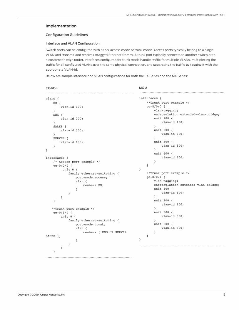
Interface and VLAN Configuration
Switch ports can be configured with either access mode or trunk mode. Access ports typically belong to a single
VLAN and transmit and receive untagged Ethernet frames. A trunk port typically connects to another switch or to
a customer’s edge router. Interfaces configured for trunk mode handle traffic for multiple VLANs, multiplexing the
traffic for all configured VLANs over the same physical connection, and separating the traffic by tagging it with the
appropriate VLAN-id.
Below are sample interface and VLAN configurations for both the EX Series and the MX Series:
EX-VC-1
vlans { HR { vlan-id 100; } ENG { vlan-id 200; } SALES { vlan-id 300; } SERVER { vlan-id 600; }}
interfaces { /* Access port example */ ge-0/0/0 { unit 0 { family ethernet-switching { port-mode access; vlan { members HR; } } } }
/*Trunk port example */ ge-0/1/0 { unit 0 { family ethernet-switching { port-mode trunk; vlan { members [ ENG HR SERVER SALES ]; } } } }
MX-A
interfaces { /*Trunk port example */ ge-8/0/0 { vlan-tagging; encapsulation extended-vlan-bridge; unit 100 { vlan-id 100; } unit 200 { vlan-id 200; } unit 300 { vlan-id 300; } unit 600 { vlan-id 600; } }} /*Trunk port example */ ge-8/0/1 { vlan-tagging; encapsulation extended-vlan-bridge; unit 100 { vlan-id 100; } unit 200 { vlan-id 200; } unit 300 { vlan-id 300; } unit 600 { vlan-id 600; } }}
6 Copyright © 2009, Juniper Networks, Inc.
IMPLEMENTATION GUIDE - Implementing a Layer 2 Enterprise Infrastructure with RSTP
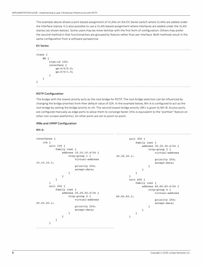
The example above shows a port-based assignment of VLANs on the EX Series switch where VLANs are added under
the interface stanza. It is also possible to use a VLAN-based assignment where interfaces are added under the VLAN
stanza (as shown below). Some users may be more familiar with the first form of configuration. Others may prefer
the second method in that functionalities are grouped by feature rather than per interface. Both methods result in the
same configuration from a software perspective.
EX Series:
vlans { HR { vlan-id 100; interface { ge-0/0/0.0; ge-0/0/1.0; } }}
RSTP Configuration
The bridge with the lowest priority acts as the root bridge for RSTP. The root bridge selection can be influenced by
changing the bridge priorities from their default value of 32K. In the example below, MX-A is configured to act as the
root bridge by setting the bridge priority to 4K. The second lowest bridge priority (8K) is given to MX-B. Access ports
are configured manually as edge ports to allow them to converge faster (this is equivalent to the “portfast” feature on
other non-Juniper platforms). All other ports are set to point-to-point.
IRBs and VRRP Configuration
MX-A:
interfaces { irb { unit 100 { family inet { address 10.10.10.4/24 { vrrp-group 1 { virtual-address 10.10.10.1; priority 254; accept-data; } } } } unit 200 { family inet { address 20.20.20.4/24 { vrrp-group 2 { virtual-address 20.20.20.1; priority 254; accept-data; } } } }
unit 300 { family inet { address 30.30.30.4/24 { vrrp-group 3 { virtual-address 30.30.30.1; priority 254; accept-data; } } } } unit 600 { family inet { address 60.60.60.4/24 { vrrp-group 4 { virtual-address 60.60.60.1; priority 254; accept-data; } } } }

Copyright © 2009, Juniper Networks, Inc. 7
IMPLEMENTATION GUIDE - Implementing a Layer 2 Enterprise Infrastructure with RSTP
An IRB is configured on the MX Series in two steps:
1. Configuring the IRB interface using the irb statement.
2. Referencing the IRB interface at the bridge domain level of the configuration.
VRRP can be configured on the IRB interface so that redundant links can be used to carry traffic between the bridge
domain and the router network.
The example below shows IRBs configured with VRRP groups and virtual addresses. The priority is set to 254 for groups
1, 2, and 4 on MX-A. This makes MX-A the master for these groups, while MX-B will be left with the default priority of
100 and will act as the backup. The “accept-data” command allows an IRB interface to accept packets destined for
virtual IP address.
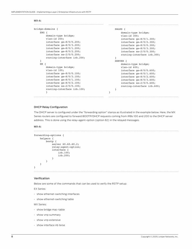
Bridge Domains Configuration
Bridge domains limit the scope of MAC learning (and thereby the size of the MAC table). They also determine where
the device should propagate frames sent to broadcast, unknown unicast, and multicast MAC addresses. Each interface
belonging to a bridge domain needs to be referenced under the corresponding bridge domain stanza. IRB interfaces are
also referenced using the “routing-interface” statement as shown below:
MX-A:
interfaces { irb { unit 100 { family inet { address 10.10.10.4/24 { vrrp-group 1 { virtual-address 10.10.10.1; priority 254; accept-data; } } } } unit 200 { family inet { address 20.20.20.4/24 { vrrp-group 2 { virtual-address 20.20.20.1; priority 254; accept-data; } } } }
unit 300 { family inet { address 30.30.30.4/24 { vrrp-group 3 { virtual-address 30.30.30.1; priority 254; accept-data; } } } } unit 600 { family inet { address 60.60.60.4/24 { vrrp-group 4 { virtual-address 60.60.60.1; priority 254; accept-data; } } } } }}
8 Copyright © 2009, Juniper Networks, Inc.
IMPLEMENTATION GUIDE - Implementing a Layer 2 Enterprise Infrastructure with RSTP
DHCP Relay Configuration
The DHCP server is configured under the “forwarding option” stanza as illustrated in the example below. Here, the MX
Series routers are configured to forward BOOTP/DHCP requests coming from IRBs 100 and 200 to the DHCP server
address. This is done using the relay-agent-option (option 82) in the relayed messages.
MX-A:
forwarding-options { helpers { bootp { server 60.60.60.2; relay-agent-option; interface { irb.100; irb.200; } } }}
Verification
Below are some of the commands that can be used to verify the RSTP setup:
EX Series:
• show ethernet-switching interfaces
• show ethernet-switching table
MX Series:
• show bridge mac-table
• show vrrp summary
• show vrrp extensive
• show interface irb terse
MX-A:
bridge-domains { ENG { domain-type bridge; vlan-id 200; interface ge-8/0/0.200; interface ge-8/0/3.200; interface ge-8/0/1.200; interface ge-8/0/2.200; interface xe-2/0/0.200; routing-interface irb.200; } HR { domain-type bridge; vlan-id 100; interface ge-8/0/0.100; interface ge-8/0/3.100; interface ge-8/0/1.100; interface ge-8/0/2.100; interface xe-2/0/0.100; routing-interface irb.100; }
SALES { domain-type bridge; vlan-id 300; interface ge-8/0/1.300; interface ge-8/0/2.300; interface ge-8/0/0.300; interface ge-8/0/3.300; interface xe-2/0/0.300; routing-interface irb.300; } SERVER { domain-type bridge; vlan-id 600; interface ge-8/0/0.600; interface ge-8/0/1.600; interface ge-8/0/2.600; interface ge-8/0/3.600; interface xe-2/0/0.600; routing-interface irb.600; }}

Copyright © 2009, Juniper Networks, Inc. 9
IMPLEMENTATION GUIDE - Implementing a Layer 2 Enterprise Infrastructure with RSTP
Both:
• show spanning-tree interface
• show spanning-tree bridge
• show spanning-tree statistics interface
Troubleshooting
The following commands can be used for troubleshooting RSTP:
EX Series:
• clear ethernet-switching table
• restart ethernet-switching
M Series:
• show bootp statistics
Both:
• monitor traffic interface <name> layer2-headers
• monitor traffic interface <name> size <size> detail
• set protocols rstp traceoptions file <filename>
• set protocols rstp traceoptions flag all
• show system core-dumps
Implementation Example
Network Topology
In our topology, RSTP is enabled on all of the trunk and access ports on the EX Series as well as the trunk ports on the
MX Series. MX-A is set as the RSTP root bridge. The following diagram shows the resulting logical topology indicating
port states and roles:
Figure 1: Network diagram with RSTP
IRB 100: 10.10.10.3/24IRB 200: 20.20.20.3/24IRB 300: 30.30.30.3/24
IRB 600: 60.60.60.3/24
VRRPGroup 1: 10.10.10.1/24
Group 2: 20.20.20.1/24Group 3: 30.30.30.1/24Group 4: 60.60.60.1/24
IRB 100: 10.10.10.4/24IRB 200: 20.20.20.4/24IRB 300: 30.30.30.4/24IRB 600: 60.60.60.4/24
VL
AN
60
0
VL
AN
10
0
VL
AN
10
0, 2
00
VL
AN
20
0
VL
AN
30
0
VL
AN
30
0
VL
AN
30
0
VL
AN
30
0
VL
AN
30
0
VL
AN
30
0
VL
AN
10
0
VL
AN
10
0,2
00
VL
AN
20
0
201/1
ge-0/0/22
ge-0/1/0
ge-1/0/0 ge-8/0/3
ge-1/0/1 ge-8/0/2ge-1/0/2 ge-8/0/1
ge-1/0/3 ge-8/0/0
xe-2/0/0 xe-2/0/0
vlan 10
0, 20
0, 30
0, 60
0
vlan
100
, 20
0, 3
00
, 60
0 vla
n 1
00
, 20
0, 3
00
, 60
0
vlan 10
0, 200, 3
00, 600vlan 100, 200, 300, 600
vlan 100, 200, 300, 600 vlan 100, 200, 300, 600
vlan 100, 20
0, 300, 60
0
ge-0/1/1 ge-0/1/0 ge-0/1/1 ge-0/1/0 ge-0/1/1 ge-0/1/0 ge-0/1/1
DHCP server60.60.60.2/24
DHCP client DHCP client DHCP client DHCP clientIP: 30.30.30.100/24GW: 30.30.30.1
IP: 30.30.30.101/24GW: 30.30.30.1
IP: 30.30.30.102/24GW: 30.30.30.1
IP: 30.30.30.103/24GW: 30.30.30.1
ge-0/0/0 ge-0/0/0ge-0/0/23 ge-0/0/1 ge-0/0/0 ge-0/0/23 ge-0/0/1ge-0/0/0 ge-0/0/23 ge-0/0/23ge-0/0/1 ge-0/0/1
201/3 201/4 201/2Agilent N2X tester
172.19.59.28
RSTP
MX-B MX-A
EX-VC-1 EX-VC-2 EX-VC-3 EX-VC-4
VLAN 100 VLAN 200 VLAN 300 VLAN 600 FWD/ROOT BLK/ALT FWD/DESG

10 Copyright © 2009, Juniper Networks, Inc.
IMPLEMENTATION GUIDE - Implementing a Layer 2 Enterprise Infrastructure with RSTP
Hardware Used for Validation
The following platforms are needed to implement the topology described:
• Four EX4200 line Ethernet switches.
• Two MX Series 3D Universal Edge Routers: Juniper Networks MX240 3D Universal Edge Router, MX480 3D Universal
Edge Router, or MX960 3D Universal Edge Router. We have used one MX480 and one MX960 for the aggregation
devices.
Table 1: Hardware
EQUIPMENT COMPONENTS
4 x EX4200 • 4 x 4-port uplink Gigabit Ethernet module (EX-UM-4SFP)
• 21 small form-factor pluggable transceivers (SFPs)
1 x MX480
1 x MX960
(XFPs)
Testing Equipment Used for Validation
Table 2: Testing Equipment
EQUIPMENT COMPONENTS
Agilent N2X tester 4 x 10/100/1000 Mb ports
Linux DHCP server
Software Used for Validation
Table 3: Software
EQUIPMENT COMPONENTS
EX Series and MX Series Junos OS 9.0

Copyright © 2009, Juniper Networks, Inc. 11
IMPLEMENTATION GUIDE - Implementing a Layer 2 Enterprise Infrastructure with RSTP
Detailed Configurations
The detailed configurations for EX-VC-1 and MX-A are listed below:
EX-VC-1
…truncated
interfaces { ge-0/0/0 { unit 0 { family ethernet-switching { port-mode access; vlan { members HR; } } } } ge-0/0/1 { unit 0 { family ethernet-switching { port-mode access; vlan { members ENG; } } } } ge-0/0/22 { ether-options { link-mode full-duplex; speed { 100m; } } unit 0 { family ethernet-switching { port-mode access; vlan { members SERVER; } } } } ge-0/0/23 { unit 0 { family ethernet-switching { port-mode trunk; vlan { members [ HR ENG ]; } } } } ge-0/1/0 { enable; unit 0 { family ethernet-switching { port-mode trunk; vlan { members [ ENG HR SERVER SALES ]; } }
MX-A
…truncated
interfaces { ge-1/0/0 { vlan-tagging; encapsulation extended-vlan-bridge; unit 100 { vlan-id 100; } unit 200 { vlan-id 200; } unit 300 { vlan-id 300; } unit 600 { vlan-id 600; } } ge-1/0/1 { vlan-tagging; encapsulation extended-vlan-bridge; unit 100 { vlan-id 100; } unit 200 { vlan-id 200; } unit 300 { vlan-id 300; } unit 600 { vlan-id 600; } } ge-1/0/2 { vlan-tagging; encapsulation extended-vlan-bridge; unit 100 { vlan-id 100; } unit 200 { vlan-id 200; } unit 300 { vlan-id 300; } unit 600 { vlan-id 600; } } ge-1/0/3 { vlan-tagging; encapsulation extended-vlan-bridge; unit 100 { vlan-id 100; } unit 200 { vlan-id 200;

12 Copyright © 2009, Juniper Networks, Inc.
IMPLEMENTATION GUIDE - Implementing a Layer 2 Enterprise Infrastructure with RSTP
} } ge-0/1/1 { enable; unit 0 { family ethernet-switching { port-mode trunk; vlan { members [ HR SERVER ENG SALES ]; } } } } ge-0/1/2 { unit 0 { family ethernet-switching; } } ge-0/1/3 { unit 0 { family ethernet-switching; } } vme { unit 0 { family inet { address 172.19.59.190/24; } } }}protocols { rstp { interface ge-0/0/0.0 { edge; } interface ge-0/0/1.0 { edge; } interface ge-0/1/0.0 { mode point-to-point; } interface ge-0/1/1.0 { mode point-to-point; } }}vlans { ENG { vlan-id 200; } HR { vlan-id 100; } SALES { vlan-id 300; } SERVER { vlan-id 600; }}
} unit 300 { vlan-id 300; } unit 600 { vlan-id 600; } } xe-2/0/0 { vlan-tagging; encapsulation extended-vlan-bridge; unit 100 { vlan-id 100; } unit 200 { vlan-id 200; } unit 300 { vlan-id 300; } unit 600 { vlan-id 600; } } irb { unit 100 { family inet { address 10.10.10.3/24 { vrrp-group 1 { virtual-address 10.10.10.1; accept-data; } } } } unit 200 { family inet { address 20.20.20.3/24 { vrrp-group 2 { virtual-address 20.20.20.1; accept-data; } } } } unit 300 { family inet { address 30.30.30.3/24 { vrrp-group 3 { virtual-address 30.30.30.1; accept-data; } } } } unit 600 { family inet { address 60.60.60.3/24 { vrrp-group 4 { virtual-address 60.60.60.1; accept-data; }

Copyright © 2009, Juniper Networks, Inc. 13
IMPLEMENTATION GUIDE - Implementing a Layer 2 Enterprise Infrastructure with RSTP
} } } } lo0 { unit 0 { family inet { address 127.0.0.1/32; } } }}forwarding-options { helpers { bootp { server 60.60.60.2; relay-agent-option; interface { irb.100; irb.200; } } }}protocols { vrrp { traceoptions { file vrrp; flag general; flag state; } } rstp { bridge-priority 8k; interface ge-1/0/0 { mode point-to-point; } interface ge-1/0/1 { mode point-to-point; } interface ge-1/0/2 { mode point-to-point; } interface ge-1/0/3 { mode point-to-point; } interface xe-2/0/0 { mode point-to-point; } }}bridge-domains { ENG { domain-type bridge; vlan-id 200; interface ge-1/0/0.200; interface ge-1/0/3.200; interface ge-1/0/1.200; interface ge-1/0/2.200; interface xe-2/0/0.200; routing-interface irb.200; } HR { domain-type bridge; vlan-id 100; interface ge-1/0/0.100;

14 Copyright © 2009, Juniper Networks, Inc.
IMPLEMENTATION GUIDE - Implementing a Layer 2 Enterprise Infrastructure with RSTP
interface ge-1/0/3.100; interface ge-1/0/1.100; interface ge-1/0/2.100; interface xe-2/0/0.100; routing-interface irb.100; } SALES { domain-type bridge; vlan-id 300; interface ge-1/0/1.300; interface ge-1/0/2.300; interface ge-1/0/0.300; interface ge-1/0/3.300; interface xe-2/0/0.300; routing-interface irb.300; } SERVER { domain-type bridge; vlan-id 600; interface ge-1/0/0.600; interface ge-1/0/1.600; interface ge-1/0/2.600; interface ge-1/0/3.600; interface xe-2/0/0.600; routing-interface irb.600; }}
Copyright © 2009, Juniper Networks, Inc. 15
IMPLEMENTATION GUIDE - Implementing a Layer 2 Enterprise Infrastructure with RSTP
Summary
With the EX Series Ethernet Switches and MX Series 3D Universal Edge Routers, Juniper Networks offers its enterprise
customers compelling end-to-end solutions that can meet the requirements of either Layer 2 or Layer 3 deployments.
In Layer 2 environments, network administrators are faced with the task of preventing and possibly troubleshooting
loops. This document shows how to implement a layer design using RSTP. Three other designs using MSTP, RTGs, and
Virtual Chassis technology are described in separate implementation guides.
With the guidelines presented in these documents, Juniper Networks customers can integrate the EX Series and
MX Series into their Layer 2 networks. They can later enable Layer 3 on the same devices without additional cost to
leverage feature-rich Junos OS while minimizing capital and operational expenses.
Appendix A: Conventions/Glossary
BOOTP Bootstrap Protocol
BPDU Bridge protocol data unit
DHCP Dynamic Host Configuration Protocol
DPC Dense Port Concentrator
IRB Integrated routing and bridging
MSTP Multiple Spanning Tree Protocol
PVST Per-VLAN Spanning Tree
RSTP Rapid Spanning Tree
RTG Redundant Trunk Group
RVI Routed VLAN Interface
STP Spanning Tree Protocol
SFP Small form-factor pluggable transceiver
VLAN Virtual LAN
VRRP Virtual Router Redundancy Protocol
VSTP Virtual Spanning Tree Protocol
XFP 10-gigabit small form-factor pluggable transceiver

16 Copyright © 2009, Juniper Networks, Inc.
IMPLEMENTATION GUIDE - Implementing a Layer 2 Enterprise Infrastructure with RSTP
Appendix B: Detailed Configurations
MX-B
…truncated
interfaces { xe-2/0/0 { vlan-tagging; encapsulation extended-vlan-bridge; unit 100 { vlan-id 100; } unit 200 { vlan-id 200; } unit 300 { vlan-id 300; } unit 600 { vlan-id 600; } } /* Trunk example */ ge-8/0/0 { vlan-tagging; encapsulation extended-vlan-bridge; unit 100 { vlan-id 100; } unit 200 { vlan-id 200; } unit 300 { vlan-id 300; } unit 600 { vlan-id 600; } } ge-8/0/1 { vlan-tagging; encapsulation extended-vlan-bridge; unit 100 { vlan-id 100; } unit 200 { vlan-id 200; } unit 300 { vlan-id 300; } unit 600 { vlan-id 600; } } ge-8/0/2 { vlan-tagging; encapsulation extended-vlan-bridge; unit 100 { vlan-id 100; } unit 200 { vlan-id 200;

Copyright © 2009, Juniper Networks, Inc. 17
IMPLEMENTATION GUIDE - Implementing a Layer 2 Enterprise Infrastructure with RSTP
} unit 300 { vlan-id 300; } unit 600 { vlan-id 600; } } ge-8/0/3 { vlan-tagging; encapsulation extended-vlan-bridge; unit 100 { vlan-id 100; } unit 200 { vlan-id 200; } unit 300 { vlan-id 300; } unit 600 { vlan-id 600; } } irb { unit 100 { family inet { address 10.10.10.4/24 { vrrp-group 1 { virtual-address 10.10.10.1; priority 254; accept-data; } } } } unit 200 { family inet { address 20.20.20.4/24 { vrrp-group 2 { virtual-address 20.20.20.1; priority 254; accept-data; } } } } unit 300 { family inet { address 30.30.30.4/24 { vrrp-group 3 { virtual-address 30.30.30.1; priority 254; accept-data; } } } } unit 600 { family inet { address 60.60.60.4/24 { vrrp-group 4 { virtual-address 60.60.60.1; priority 254; accept-data; }
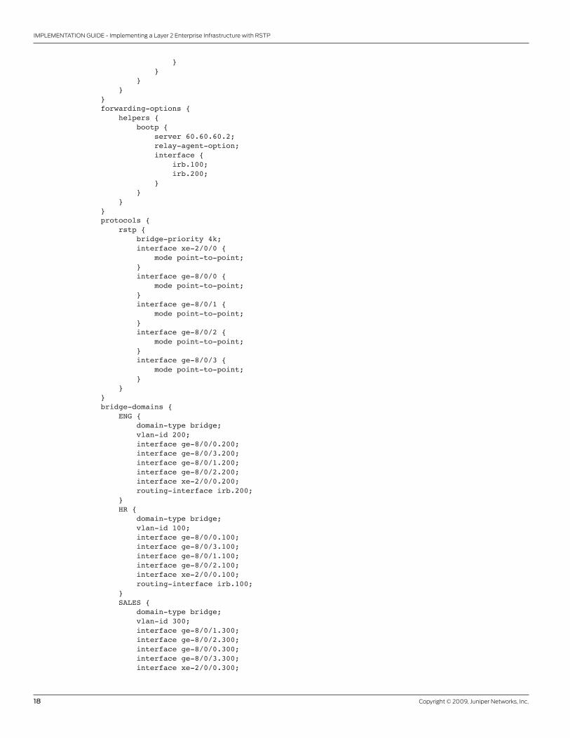
18 Copyright © 2009, Juniper Networks, Inc.
IMPLEMENTATION GUIDE - Implementing a Layer 2 Enterprise Infrastructure with RSTP
} } } }}forwarding-options { helpers { bootp { server 60.60.60.2; relay-agent-option; interface { irb.100; irb.200; } } }}protocols { rstp { bridge-priority 4k; interface xe-2/0/0 { mode point-to-point; } interface ge-8/0/0 { mode point-to-point; } interface ge-8/0/1 { mode point-to-point; } interface ge-8/0/2 { mode point-to-point; } interface ge-8/0/3 { mode point-to-point; } }}bridge-domains { ENG { domain-type bridge; vlan-id 200; interface ge-8/0/0.200; interface ge-8/0/3.200; interface ge-8/0/1.200; interface ge-8/0/2.200; interface xe-2/0/0.200; routing-interface irb.200; } HR { domain-type bridge; vlan-id 100; interface ge-8/0/0.100; interface ge-8/0/3.100; interface ge-8/0/1.100; interface ge-8/0/2.100; interface xe-2/0/0.100; routing-interface irb.100; } SALES { domain-type bridge; vlan-id 300; interface ge-8/0/1.300; interface ge-8/0/2.300; interface ge-8/0/0.300; interface ge-8/0/3.300; interface xe-2/0/0.300;

Copyright © 2009, Juniper Networks, Inc. 19
IMPLEMENTATION GUIDE - Implementing a Layer 2 Enterprise Infrastructure with RSTP
routing-interface irb.300; } SERVER { domain-type bridge; vlan-id 600; interface ge-8/0/0.600; interface ge-8/0/1.600; interface ge-8/0/2.600; interface ge-8/0/3.600; interface xe-2/0/0.600; routing-interface irb.600; }
}
EX-VC-2
…truncated
interfaces { ge-0/0/0 { unit 0 { family ethernet-switching { port-mode access; vlan { members SALES; } } } } ge-0/0/1 { unit 0 { family ethernet-switching { port-mode access; vlan { members SALES; } } } } ge-0/0/23 { unit 0 { family ethernet-switching { port-mode access; vlan { members SALES; } } } } ge-0/1/0 { unit 0 { family ethernet-switching { port-mode trunk; vlan { members [ SALES HR ENG SERVER ]; } } } } ge-0/1/1 { unit 0 { family ethernet-switching { port-mode trunk;

20 Copyright © 2009, Juniper Networks, Inc.
IMPLEMENTATION GUIDE - Implementing a Layer 2 Enterprise Infrastructure with RSTP
vlan { members [ SALES HR ENG SERVER ]; } } } } ge-0/1/3 { unit 0 { family ethernet-switching; } } vme { unit 0 { family inet { address 172.19.59.192/24; } } }}protocols { rstp { interface ge-0/0/0.0 { edge; } interface ge-0/0/1.0 { edge; } interface ge-0/1/0.0 { mode point-to-point; } interface ge-0/1/1.0 { mode point-to-point; } }}vlans { ENG { vlan-id 200; } HR { vlan-id 100; } SALES { vlan-id 300; } SERVER { vlan-id 600; }
}
EX-VC-3
…truncated
interfaces { ge-0/0/0 { unit 0 { family ethernet-switching { vlan { members SALES; } } }

Copyright © 2009, Juniper Networks, Inc. 21
IMPLEMENTATION GUIDE - Implementing a Layer 2 Enterprise Infrastructure with RSTP
} ge-0/0/1 { unit 0 { family ethernet-switching { vlan { members SALES; } } } } ge-0/0/23 { unit 0 { family ethernet-switching { port-mode access; vlan { members SALES; } } } } ge-0/1/0 { unit 0 { family ethernet-switching { port-mode trunk; vlan { members [ SALES HR ENG SERVER ]; } } } } ge-0/1/1 { unit 0 { family ethernet-switching { port-mode trunk; vlan { members [ SALES HR ENG SERVER ]; } } } } ge-0/1/3 { unit 0 { family ethernet-switching; } } vme { unit 0 { family inet { address 172.19.59.193/24; } } }}protocols { rstp { interface ge-0/0/0.0 { edge; } interface ge-0/0/1.0 { edge; } interface ge-0/1/0.0 { mode point-to-point; } interface ge-0/1/1.0 {

22 Copyright © 2009, Juniper Networks, Inc.
IMPLEMENTATION GUIDE - Implementing a Layer 2 Enterprise Infrastructure with RSTP
mode point-to-point; } }}vlans { ENG { vlan-id 200; } HR { vlan-id 100; } SALES { vlan-id 300; } SERVER { vlan-id 600; }}
Copyright © 2009, Juniper Networks, Inc. 23
IMPLEMENTATION GUIDE - Implementing a Layer 2 Enterprise Infrastructure with RSTP
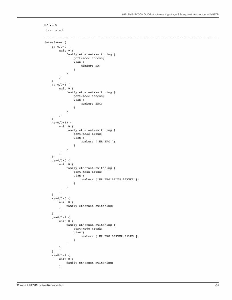
EX-VC-4
…truncated
interfaces { ge-0/0/0 { unit 0 { family ethernet-switching { port-mode access; vlan { members HR; } } } } ge-0/0/1 { unit 0 { family ethernet-switching { port-mode access; vlan { members ENG; } } } } ge-0/0/23 { unit 0 { family ethernet-switching { port-mode trunk; vlan { members [ HR ENG ]; } } } } ge-0/1/0 { unit 0 { family ethernet-switching { port-mode trunk; vlan { members [ HR ENG SALES SERVER ]; } } } } xe-0/1/0 { unit 0 { family ethernet-switching; } } ge-0/1/1 { unit 0 { family ethernet-switching { port-mode trunk; vlan { members [ HR ENG SERVER SALES ]; } } } } xe-0/1/1 { unit 0 { family ethernet-switching; }

8010066-001-EN Dec 2009
Copyright 2009 Juniper Networks, Inc. All rights reserved. Juniper Networks, the Juniper Networks logo, Junos, NetScreen, and ScreenOS are registered trademarks of Juniper Networks, Inc. in the United States and other countries. All other trademarks, service marks, registered marks, or registered service marks are the property of their respective owners. Juniper Networks assumes no responsibility for any inaccuracies in this document. Juniper Networks reserves the right to change, modify, transfer, or otherwise revise this publication without notice.
EMEA Headquarters
Juniper Networks Ireland
Airside Business Park
Swords, County Dublin, Ireland
Phone: 35.31.8903.600
EMEA Sales: 00800.4586.4737
Fax: 35.31.8903.601
APAC Headquarters
Juniper Networks (Hong Kong)
26/F, Cityplaza One
1111 King’s Road
Taikoo Shing, Hong Kong
Phone: 852.2332.3636
Fax: 852.2574.7803
Corporate and Sales Headquarters
Juniper Networks, Inc.
1194 North Mathilda Avenue
Sunnyvale, CA 94089 USA
Phone: 888.JUNIPER (888.586.4737)
or 408.745.2000
Fax: 408.745.2100
www.juniper.net
To purchase Juniper Networks solutions,
please contact your Juniper Networks
representative at 1-866-298-6428 or
authorized reseller.
Printed on recycled paper
24 Copyright © 2009, Juniper Networks, Inc.
IMPLEMENTATION GUIDE - Implementing a Layer 2 Enterprise Infrastructure with RSTP
} vme { unit 0 { family inet { address 172.19.59.189/24; } } }}protocols { rstp { interface ge-0/0/0.0 { edge; } interface ge-0/0/1.0 { edge; } interface ge-0/1/0.0 { mode point-to-point; } interface ge-0/1/1.0 { mode point-to-point; } }}vlans { ENG { vlan-id 200; } HR { vlan-id 100; } SALES { vlan-id 300; } SERVER { vlan-id 600; }}
About Juniper Networks
Juniper Networks, Inc. is the leader in high-performance networking. Juniper offers a high-performance network
infrastructure that creates a responsive and trusted environment for accelerating the deployment of services and
applications over a single network. This fuels high-performance businesses. Additional information can be found at
www.juniper.net.