Embed Size (px)
Citation preview

283Suranaree J. Sci. Technol. Vol. 21 No. 4; October - December 2014
IMPLEMENTATION OF WIRELESS CHARGER FOR MOBILE PHONE BASED ON SOLAR ENERGY Talit Jumphoo1, Peerapong Uthansakul1*, and Hoi-Shun Lui2
Received: November 20, 2014; Revised: December 08, 2014; Accepted: December 09, 2014
Abstract
Recently, technology that can promise to energize devices without a wired connection has caught the attention of researchers around the world. Moreover, if this technology can provide the ability to harvest energy from the environment, then it can provide a long-life battery for many important applications and permit the deployment of self-energized devices. This paper presents the use of solar energy to chargea mobile phone with a wireless connection. The design and implementation of the proposed system have been undertaken. The measured results indicate that the proposed system can be used as a wireless charger powered by solar energy. The prototype sourced by solar energy has been tested outdoors from 10:00-17:00 for 3 days. The results show that light intensity plays the main role in the charging time of the wireless charger.
Keywords: Wireless charger, solar energy, transformer, magnetic flux
Introduction Self-energized devices can be powered by different kinds ofenergy, including radio frequency, solar, thermal, andvibration. In addition, a single device can be energized from multiple ambient energy sources (Park, 2005; Ferro Solutions, 2004). Radio frequency (RF) devices utilize electromagnetic radiation emitted by radio devices, such as wireless radio networks. As the most commonly used frequencies are wellknown, the devices have an antenna and circuitry tuned tomaximize energy harvesting at these frequencies.
Unfortunately, typical electric field strengths are weak(unless located close to sources), which severely limits the quantity of energy that can be harvested, e.g., to approximately 2 orders of magnitude less than indoor solar and thermoelectric devices. Active systems attempt toovercome this limit by broadcasting RF energy, as is donecurrently for radio frequency identification tags used in commercial enterprises (Paradiso and Starner, 2007). Thermoelectric devices consume energy developed from temperature differences via
1 School of Telecommunication Engineering, Suranaree University of Technology, Muang, Nakhon Ratchasima, Thailand 30000. 2 School of Information Technology and Electrical Engineering, The University of Queensland, Brisbane St Lucia, QLD, 4072, Australia, E-mail: [email protected], [email protected], [email protected] * Corresponding author
Suranaree J. Sci. Technol. 21(4):283-291
Implementation of Wireless Charger for Mobile Based Solar 284
the Seebeck effect, i.e., atemperature difference at the junction of 2 metals or semiconductors causes current to flow across the junction.The power density of thermoelectric devices increases with the temperature difference, thus increasing their attractiveness in applications such as sun/ shade installations, compressors, and hot/cold/ air/water/refrigerant flows. Vibration sources extract energy from ambient vibrations. As power usually scales with the cube of vibration frequency and the square of vibration amplitude, these devices have the most value in applications with high frequency, high- amplitude vibrations. Thus, potentially promising vibration sources could include compressors, motors, pumps, blowers, and, perhaps to a lesser extent, fansand ducts. All vibration-harvesting systems contain mechanical elements that vibrate, typically a spring- mass assembly with its natural frequency close to those of the vibration source to maximize energetic coupling between the vibration source and the harvesting system. Several different ways exist to translate the vibrating elements into electricenergy, including piezoelectric (Boonruang et al., 2012; Tigunta et al., 2013), capacitive, and inductive systems (Roundy, 2003). Solar energized devices use photovoltaic (PV) cells to convert incident light into electricity (Phungsripheng et al., 2013). As such, they leverage the extensive investments made and progress achieved in increasing the efficiency and reducing the cost of PV for building- and utility-scale power. Solar devices can produce energy from both outdoor and indoor light sources, although outdoor insolation levels yield approximately 2 to 3 orders of magnitude more electricity per unit area than indoor electric light sources (Roundy 2003; Paradiso and Starner, 2007). Relative to other sources, solar devices can achieve high energy densities when used indirect sun, but will not function in areas without light (e.g., highly shaded areas, ducts). Applications to date include contact and motion sensors for building applications (Park and Chou, 2004) aswell as calculators,
personal digital assistants, and wristwatches. While a wide variety of harvesting modalities are now feasible, solarenergy harvesting through photovoltaic conversion provides the highest power density, which makes it the modality of choice to power an embedded system that consumes several mW using a reasonably small harvesting module. This paper focuses on using solar cell energyin providing an alternative power source to charge mobile phone devices. Previous works in this field can befound (Kansal and Srivastava, 2003; Voigt et al., 2003; Kansal et al., 2004). A solar harvesting augmented high-end embedded system was described by Voigt et al. (2003), in which a switch matrix was used to power individual system components from either the solar panel or the battery. Harvesting-aware protocols have also been proposed for data routing (Kansal and Srivastava, 2003), and distributed performance scaling (Kansal et al., 2004). Apart from solar energy, this paper also presents a wireless channel for power charging by converting solar energy into a wireless signal in which the mobile phone can be charged without a wired connection. The motivation for this wireless charger is as follows. Throughout the years, technology has allowed the cellular phone to shrink not only the size of the integrated circuits (IC), but also the batteries. New combinations of materials have made possible the ability to produce batteries that not only are smaller and last longer, but also can be recharged easily. However, as technology has advanced and made our phones smaller and easier to use, we still have one of the original problems: we must plug the phone into the wall in order to recharge the battery. Most people accept this as something that will never change, so they might as well accept it and carry around with them either extra batteries or a charger. Either way, it is just something extra to weigh a person down. There has been research done in the area of shrinking the charger in order to make it easier to carry with the phone. Most people donot realize that there is an
285Suranaree J. Sci. Technol. Vol. 21 No. 4; October - December 2014
abundance of energy all around us at all times. We are being bombarded with energy waves every second of the day. Radio and television towers, satellites orbiting earth, and even the cellular phone antennas are constantly transmitting energy. If it could be possible to gather the energy and store it, we could potentially use it to power other circuits. In the case of the cellular phone, this power could be used to recharge a battery that is constantly being depleted. The potential exists for cellular phones, and even more complicated devices - i.e. pocket organizers, personal digital assistants, and even notebook computers - to become completely wireless. The concept needs an efficient antenna along with a circuit capable of converting alternating-current (AC) voltage to direct- current (DC) voltage. The efficiency of an antenna, as being discussed here, is related to the shape and impedance of the antenna and the impedance of the circuit. The details of the proposed wireless charger, including the transmitting and receiving circuits,are described in the next section. Then, the experimental setup, measured results, and discussion are presented, respectively.
Components of Proposed Wireless Charger
Transmitting Circuit
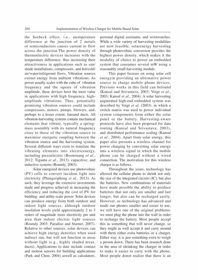
In general, there are many kinds of circuit that can convert the DC power energized by solar cells into another form. In this paper, the concept of the transformer has been adopted and modified by using only air as the medium instead of iron. This is like the induction theory from the basic principle of the electromagnetic dilemma. When the current flows into a coil, the magnetic flux will be generated and radiate in the perpendicular plane at the center of coil. This magnetic flux depends on the intensity of the current as well as the number of coils. The formula of the magnetic field can be expressed in (1).
(1) where μ0 = 4π × 10-7 H/m, I is the current, a is the diameter of the coil, and n is the number of coils. From Faraday,s law, the relationship between the electromotive force andthe magnetic flux can be given by (2).
(2) where ε is the electromotive force, ∆∅ is the changing of the magnetic flux, ∆t is the interval time of the magnetic flux changing, and N is the number of coils. The original concept of Faraday,s iron ring apparatus requires the iron to be the medium for the magnetic flux to flow across 2 coils. This concept has been modified by using air as the medium instead of an iron ring. It can be obviously realized that the efficiency of an air-core transformer is lower than iron but this can make a wireless charger for the mobile phone. For the transmitting circuit, this paper uses a transistor as an electronic amplifier to connect with a feedback loop, as illustrated in Figure 1. The point 1 of Figure 1 is the frequency filter which is designed by a resistor-capacitor (RC) circuit. The resistance and capacitance form the action of the phase-
Figure 1. Transmitting Circuit
Implementation of Wireless Charger for Mobile Based Solar 286
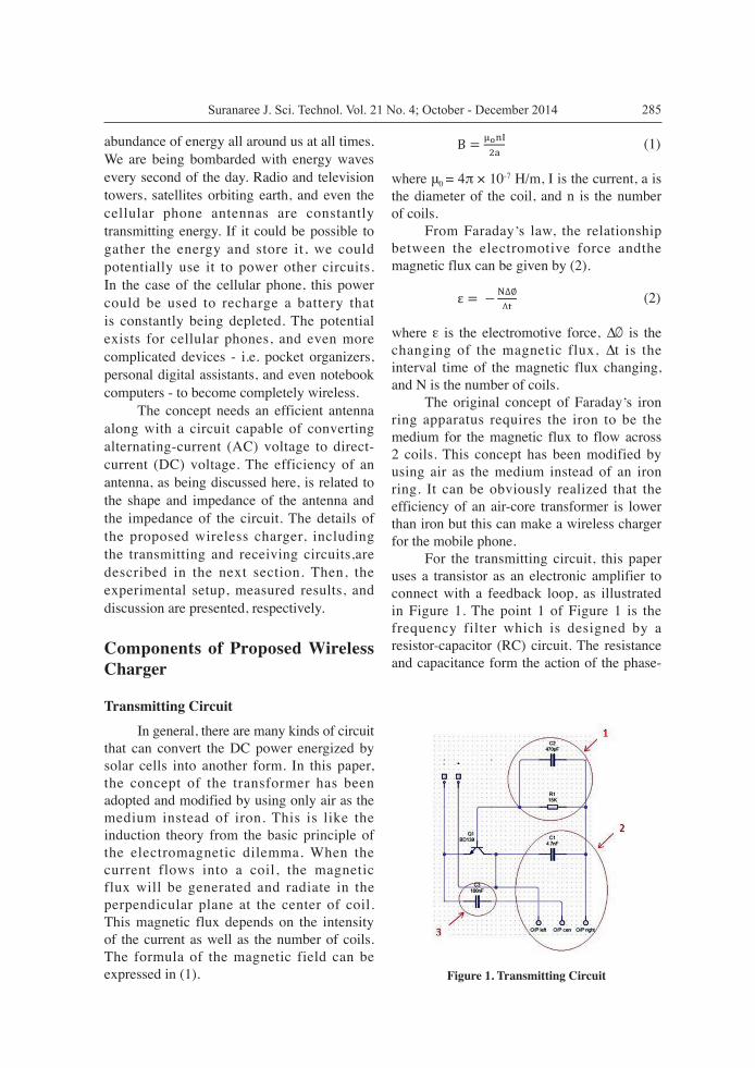
shifted oscillator in order to receive positive feedback. When the electric source is input at the amplifying circuit, the noise in the electronic circuit will make the oscillator work. After that, the inductor-capacitor (LC) circuit has been selected to tune the operating frequency, as shown in point 2 of Figure 1. The inductance and capacitance will store the electric power at the resonant frequency. At this point, the current flows into the coil and the inductive electromagnetic field will be transferred to the receiver via the air medium. The last part of the transmitting circuit is a low pass filter, as seen in point 3 of Figure 1. The inductance XL is low and the capacitance XC is high. Then, the low frequency signals can easily pass the inductive coil in which the output of the system is high. In turn, the higher frequency signals hardly pass through the filter. In the RC design, the capacitor is set to 470 pF and the resistance is 15kΩ. It is used to control the interval time between the charge and discharge process. For the tuning filter, the capacitor is set to 100 nF. The transistor BD139 is selected to amplify the signals. The capacitor matching the coil impedance is set to 4.7 nF in which the complex value of the capacitor and coil will be cancelled out by each other. Figure 2 depictsthe assembly of the wireless charger for (left) inside and (right) outside. It can be clearly seen that both the overall circuit and coil are so thin and small that all the assembly can be done easily. The
box of the wireless charger can be modified to fit with any mobile layouts.
Receiving Circuit
In the receiving circuit, the first part is the receiving coil reacting to the power transfer from the transmitter, as seen in point 1 of Figure 3. This current will be fed to the rectifier in order to convert from AC to DC. The rectifier is shown in point 2 of Figure 3. Finally, the voltage regulator will be used to control the constant level of output at 5V, as shown in point 3 of Figure 3. This regulator is very important because it is the safety check for the mobile phone. If the output voltage is not stable, the variation of the voltage will make the lifetime of the battery shorter. Moreover, it might cause the mobile phone to become broken. As seen in Figure 3, the matching part uses the capacitor at 4.7 nF. The diode 1N4148 is used to perform the AC to DC conversion. The IC LM7805 is used as the regulator to control the constant output at 5V. Figure 4 shows the assembly of the mobile phone for (left) inside and (right) outside. It is clearly seen that the circuit and coil are so thin and small that they can be placed inside the case of the mobile phone. The modified mobile phone can be used normally in all functions.
Magnetic Transferring Coil
One of the most important parts of the wireless charger is the magnetic transferring
Figure 2. Assembly of wireless charger (left) inside and (right) outside

287Suranaree J. Sci. Technol. Vol. 21 No. 4; October - December 2014
coil. This paper chooses the flat spiral coil inductor because it savesspace by spreading a number of coils over 1 flat plane, as shown in Figure 5. This is very practical because it can be installedinside the back of the case of the mobile phone. In this paper, the area of the back of the case is 5.8×1.1 cm. Therefore, the selection of copper wire has to take this area into account. That is the reason why this paper chooses copper number 22 which is suitable for the back of this case. The inductance of a coil can only be approximately calculated with an empirical formula (Grover, 1962). In this paper, the inductance is 54.03 μH at 125 kHz.
All components of the wireless charger for the mobile phone are illustrated in Figure 6 and the photograph of the prototype is presented in Figure 7. As seen in Figure 7, the dimensions of the solar cell are small and it is convenient to install it on any rooftop. Actually, there are many solar cell products in commercial use. This paper employs the popular product on the shelf which its efficiency is typical.The specification of the solar cell is as follows. The open circuit voltage is 21.2 V with an optimum operating voltage of 16.8 V. The short circuit current is 1.32 A with an optimum operating current of 1.19 A. Please note that a higher voltage
Figure 3. Receiving Circuit
Figure 4. Assembly of mobile phone (left) inside and (right) outside

Implementation of Wireless Charger for Mobile Based Solar 288
and current can be achieved if the size and quality of the solar cell is extended.
Experimental Results and Discussion Three experiments have been carried out in order to investigate the performance of the proposed system. The first experiment is to investigate the change of current and voltage from solar energy throughout the daytime. This experiment will let the researchers find the suitable time period and gap in 1 day of solar energy use. The second experiment is to compare between using the proposed system as a wireless charger and using a conventional charger as a wired charger. The results will let us know the acceptable delay when using the
wireless charger. For the last experiment, the relationship between the voltage and the distance between the charger and the mobile phone is illustrated. The results will guide the design of a proper space for installing the mobile phone. For the first experiment, the prototype shown in Figure 7 has been tested outdoors for 3 days. On each day, the measurement started at 10:00 and stopped at 17:00. Within 1 h, the data was recorded 10 times and the average value is the representative value for that interval. The results in Table 1 show that the maximum current and voltage can be achieved between the hours of 13:00-14:00. This is because at that time the sunlight provides the maximum light intensity. However,
Figure 5. Flat spiral coil
Figure 6. All components of wireless charger for mobile phone

289Suranaree J. Sci. Technol. Vol. 21 No. 4; October - December 2014
Figure 8. Voltage versus distance between wireless charger and mobile phone energized by solar cell at 11:00
Figure 7. Photograph of proposed wireless charger
the current gap between the minimum and maximum current is 75.3 mA which is very high. It means that this charger cannot be used for the whole of the daytime. This is the limit of a wireless charger which is energized by a solar cell. In the second experiment, the results in Table 2 reveal that the charging time of a conventional charger was 1.38 min to charge 1% of the battery while it took 7.24 min for the wireless charger. This is about 5.2 times longer for the wireless charger. This delay is the price for having more convenient devices which do not requirea wired connection any more.
For the last experiment, the relationship of the voltage and the distance between the wireless charger and the mobile phonewas investigated. The measurement was undertaken at 11:00. The results help the researchers to design the tradeoff between power degradation and the thickness of the case in practice. As seen in Figure 8, the minimum distance is limited to 4.5 cm because the voltage will drop below 5 V, in which case it cannot be utilized for charging the battery.
Conclusions This paper suggests the use of solar energy
Table 1. Average currents and voltages of wireless charger
Time Day 1 Day 2 Day 3 Average
Current (mA)
Voltage (V)
Current (mA)
Voltage (V)
Current (mA)
Voltage (V)
Current (mA)
Voltage (V)
10.00 108.3 10.15 115.0 10.18 122.7 10.37 115.1 10.23
11.00 101.7 10.32 102.9 10.31 103.3 10.32 102.6 10.32
12.00 139.2 10.00 132.1 9.97 140.6 10.01 137.3 9.99
13.00 145.8 10.35 144.0 10.42 141.6 10.38 143.8 10.38
14.00 145.1 10.35 144.8 10.35 145.2 10.36 145.0 10.35
15.00 110.7 10.27 110.9 10.24 113.2 10.24 111.6 10.25
16.00 97.4 10.14 97.4 10.15 96.6 10.11 97.1 10.13
17.00 68.8 9.58 70.1 9.62 70.2 9.59 69.7 9.60

Implementation of Wireless Charger for Mobile Based Solar 290
inmobile phone devices in cooperation with wireless charging technology. The results of this paper indicate that it is possible to use solar energy to supply mobile phonebatteries with the necessary power. Also the prototype proves that the implementation is simple and it can be done easily for public use. Although the charging time of wireless charger is 5.2 times longer, there is no need to pay for the cost of electricity. This can be a free energy source for devices in daily use.
References Boonruang, A., Ngernchuklin, P., Daungdaw, S., and
Eamchotchawalit, C. (2012). Influence of milling method on the electrical properties of 0.65PMN-
0.35PT ceramics. Suranaree J. Sci. Technol., 19(4):251-257.
Ferro Solutions (2004). VEH-360: Evaluation Power System Specifications. Elsevier, NY, 605p.
Grover, F.W. (1962). Inductance Calculations: Working Formulas and Tables. Dover Publications, Inc., Mineola, NY, USA, 304p.
Kansal, A. and Srivastava, M. (2003). An environmental energy harvesting framework for sensor networks. Proceedings of the ACM International Symposium on Low Power Electronics and Design; August 25-27, 2003; Seoul, South Korea, p. 481-486.
Kansal, A., Potter, D., and Srivastava, M. (2004). Performance aware tasking for environmentally powered sensor networks. Proceedings of the Joint ACM International Conference on Measurement and Modeling of Computer Systems; June 12-16, 2004; New York, NY, USA, p. 223-234.
Table 2. Comparison of charging time between wire and wireless chargers for charging 1% battery
Type of Charger Number of Iterations
Wire (min)
Wireless (min)
1 1.39 7.27
2 1.35 7.13
3 1.48 7.26
4 1.42 7.39
5 1.27 7.14
6 1.42 7.28
7 1.24 7.14
8 1.43 7.21
9 1.30 7.15
10 1.43 7.22
11 1.38 7.40
12 1.32 7.27
13 1.39 7.39
14 1.37 7.20
15 1.39 7.13
16 1.23 7.16
17 1.53 7.24
18 1.49 7.14
19 1.39 7.45
20 1.44 7.14
Average 1.38 7.24
291Suranaree J. Sci. Technol. Vol. 21 No. 4; October - December 2014
Paradiso, J.A. and Starner, T. (2007) Energy scavenging for mobile and wireless electronics. IEEE Pervas. Comput., 4(1):18-27.
Park, C. and Chou, P.H. (2004). Power utility maximization for multiple-supply systems by a load-matching switch. Proceedings of the International Symposium on Low Power Electronics and Design; August 9-11, 2004; Newport Beach, CA, USA, p. 168-173.
Park, G. (2005) Overview of energy harvesting systems (for low-power electronics). Presentation to the Los Alamos National Laboratory Engineering Institute Workshop: Energy Harvesting for Embedded SHM Sensing Systems. Engineering Institute, Los Alamos National Laboratory, Los Alamos, NM, USA, p 1-11.
Phungsripheng, S., Sanorpim, S., and Wasanapiarnpong, T. (2013). Effect of nitrogen doping on photovoltaic property of lead lanthanum zirconatetitanate ferroelectric ceramics. Suranaree J. Sci. Technol., 20(2):109-116.
Roundy, S. (2003). Energy scavenging for wireless sensor nodes with a focus on vibration-to-electricity conversion, [Ph.D. thesis]. Department of Mechanical Engineering, University of California, Berkeley, CA, USA, 287p.
Tigunta, S., Pisitpipathsin, N., Eitssayeam, S., Rujijanagul, G., Tunkasiri, T., and Pengpat, K. (2013). Effects of BZT addition on physical and electrical properties of calcium phosphate bioglass. Suranaree J. Sci. Technol., 20(3):197-203.
Voigt, T., Ritter, H., and Schiller, J. (2003). Utilizing solar power in wireless sensor networks. Proceedings of the 28th Annual IEEE Conference on Local Computer Networks; October 20-24, 2003; Seoul, South Korea, p. 1-5.