Embed Size (px)
Citation preview

Mälardalen University/2009.04.01 0
School of Innovation, Design and Engineering Bachelor Thesis Report in Computer Science 15 credit hours
IMPLEMENTATION OF SPANNING TREE PROTOCOL
IN SKINNSKATTEBERG COUNCIL’S NETWORK
BY
GENET KAHSAY-ERIKSSON
[email protected]@[email protected]@student.mdh.sedh.sedh.sedh.se
SupervisorSupervisorSupervisorSupervisor at Universityat Universityat Universityat University: Conny Collander, [email protected] SupervisorSupervisorSupervisorSupervisor at Skinnskatteberg Councilat Skinnskatteberg Councilat Skinnskatteberg Councilat Skinnskatteberg Council: : : : Steve Henriksson, [email protected] ExaminerExaminerExaminerExaminer: Mats Björkman

Mälardalen University/2009.04.01 1
Abstract
In the substation automation applications the utility of Ethernet local area networks
(LANs) that interconnects different network devices together has become so popular
and has grown steadily, there is always an anxiety on how to protect against the event
of a single link network failure? Though, the easiest way to be on the safest side is by
the creation of more than one link between two network devices, having many paths
between two network devices in the network establishes a loop (loops). A loop is very
dangerous to have in data link layer where the frame doesn’t have TTL (time to live)
counting down.[9] This can result in an endless loop in the entire LAN and put the
network down [3]. To eliminate loop in Ethernet LAN with redundant link, we can use
one of the data link layer protocol which is called STP (Spanning Tree Protocol).
In the past STP was not so popular but today more and more enterprises are beginning
to use the STP. But not only companies have found the Spanning Tree Protocol to be
very interesting, other establishments like schools, hospitals, businesses etc have also
found this a great reliable protocol to have.
This thesis is focused on the study of how to create a redundancy link on the
Skinnskatteberg council’s network and protecting loops by implementing the Spanning
Tree Protocol on a fast growing council in the central region of Sweden. Actually the
study is also useful to utilize in other LAN switched networks.

Mälardalen University/2009.04.01 2
Sammanfattning
Användning av Ethernet lokal area i ett industriellt bruk som sammankopplar många nätverks utrustningar tillsammans har blivit så populärt och har växt stadigt, men det finns alltid en oro om hur man kan skydda sig mot ett enda nätverklänksfel? Men det enklaste sättet att vara på den säkra sidan är genom att det skapas mer än en länk mellan två nätverksenheter, med många vägar mellan två nätverksenheter i nätet upprättas en slinga (loopar). En slinga är mycket farligt att ha i datalänklager där frame inte har TTL (time to live) nedräkning. Detta kan resultera i en oändlig loop i hela LAN och sätta ned nätet[3]. För att eliminera loop Ethernet LAN med redundanta länkar kan vi använda ett Datalänklagerprotokoll som kallas STP (Spanning Tree Protocol). Under de senaste åren var STP inte så populärt men i dag har fler och fler företag börjat använda STP. Men det är inte bara företag som har hittat att Spanning Tree Protocol är mycket intressant, även andra anläggningar såsom skolor och sjukhus, etc har också visat att detta är ett mycket pålitligt protokoll att ha. Det här examensarbetet är fokuserat på en studie om hur man skapar en redundanslänk på Skinnskatteberg kommuns nätverk, och skydda loopar genom att genomföra Spanning Tree-protokollet på en snabbt växande kommun i den centrala regionen av Sverige. Egentligen är studien också bra att använda i andra switchade LAN-nät.

Mälardalen University/2009.04.01 3
Acknowledgement
I would like to sincerely thank my lovely mother Mihret Habte, my brothers Afeworki
and Kibrom for their moral support and encouragement. My gratitude to my family
specially my children Patrik, David, Emilia and my husband Stefan who were able to
withstand my absence from home for long hours just to stay in school to be able to
come to an end to this thesis.
I will also like to thank my best friend Victor for encouragement, proofreading and
advice from start to end, without hesitating. Without him I would not have come to
this point. I would like to say thanks a lot to Mats-Göran Oscarsson for he is taking
time to proof-read this report.
I will also like to say a big thank you to my Supervisor Steve Henriksson for his time
and willingness to accept me working in their council.
Thanks to my Supervisor Conny Collander for he is taking time to comment on this
report. Last in the list but first in my heart, God Almighty for strength, wisdom and
intelligence for the years I have spent at school.

Mälardalen University/2009.04.01 4
SOME DEFINITIONS AND ABBREVIATIONS:
STP: Spanning Tree Protocol
BPDU: Bridge Protocol Data Units
IEEE 802/1D: The Institute of Electrical and Electronics Engineers Media
Access Control (MAC) Bridges
RSTP: Rapid Spanning Tree Protocol
MSTP: Multiple Spanning Tree Protocol
PVST: Per-Vlan Spanning Tree
R-PVST: Rapid Per-VLAN Spanning Tree
LAN: Local Area Network
Mpbs: Mega byte per second
MAC address: Media Access Control
DP: Designated port
BID: Bridge Identifier
CBPDU: Configuration Bridge Protocol Data Units
TCN: Topology Change Notification
TCA: Topology Change Notification Acknowledgement
DLS: Distribution Layer Switch
ALS: Access Layer Switch
VRRP: Virtual Router Redundancy Protocol
FEC: Fast EtherChannel

Mälardalen University/2009.04.01 5
LIST OF FIGURES AND TABLE FIGURE 1 ............................................................................................................. 8 FIGURE 2.1 .......................................................................................................... 9 FIGURE 2.2 ........................................................................................................ 12 FIGURE 2.3 ........................................................................................................ 13 FIGURE 2.4 ........................................................................................................ 17 FIGURE 2.5 ........................................................................................................ 20 FIGURE 2.6 ........................................................................................................ 21 FIGURE 2.7 ........................................................................................................ 22 FIGURE 6 ........................................................................................................... 24 FIGURE 6.1 ........................................................................................................ 25 TABLE 2.4 .......................................................................................................... 16

Mälardalen University/2009.04.01 6
Table of Contents
1. INTRODUCTION ......................................................................................................... 8 1.1 Background ................................................................................................ 9
2. SPANNING TREE PROTOCOL .............................................................................. 10 2.1 Root Bridge .............................................................................................. 10 2.2 Bridge Protocol Data Units (BPDU) ........................................................ 11 2.3 Configuration of Spanning Tree Protocol ................................................ 13 2.3.1 Role of STP Ports ........................................................................... 13 2.3.1.1 Root Port ........................................................................... 13 2.3.1.2 Designated Port ................................................................. 13 2.3.1.3 Non Designated Port ......................................................... 14 2.3.1.4 Disabled Port ..................................................................... 14 2.3.2 State of the STP Ports .................................................................... 14 2.3.2.1 Blocking ........................................................................... 15 2.3.2.2 Listening ........................................................................... 16 2.3.2.3 Learning ........................................................................... 16 2.3.2.4 Forwarding ....................................................................... 16 2.3.2.5 Disabled ........................................................................... 17 2.4 THE OPERATION OF A SPANNING TREE ....................................... 17 2.5 DESIGNATED PORTS WHAT ARE THEY? ...................................... 20 2.6 CONVERGENCE ................................................................................... 22 2.7 VIRTUAL ROUTER REDUNDANCY PROTOCOL ........................... 23
3. THE FORMULATION OF PROBLEM .................................................................. 26
4. ANALYSIS OF THE PROBLEM ........................................................................................ 27
5. METHODS .................................................................................................................. 28 5.1 HP ProCurve Switch versus Cisco Catalyst Switch ........................... 28
5.1.1 To configure STP on Hp switch 2650 ......................................... 29 5.1.2 To configure STP on Cisco catalyst switch 3560 ........................ 29 5.1.3 To configure STP per VLAN on Cisco Switch 3560 ................. 29 5.1.4 To configure PVST+ on Cisco Switch ....................................... 29 5.1.5 To configure Backbonefast and Uplinkfast on Cisco Switch ...... 29
5.2 EtherChannel ....................................................................................... 30 5.3 IEEE 802.3ad Link Bundling .............................................................. 30 5.4 Trunking in Cisco Switch and Tagging in HP Switch ........................ 30
6. SOLUTION TO THE PROBLEM ............................................................................ 32 6.1 Creation of Redundant Link .................................................................... 33 6.2 Using STP TECHNIQUE ........................................................................ 34 6.2.1 Selection of Root Bridge ................................................................ 34 6.2.2 Selection of Port Role .................................................................... 34

Mälardalen University/2009.04.01 7
7. RESULT AND DISCUSSIONS ................................................................................. 35
8. DISCUSSIONS ............................................................................................................ 35
9. LIMITATIONS .......................................................................................................... 37
10. PROPOSAL FOR CONTINUATION OF STUDY ............................................... 37
References: .......................................................................................................... 39

Mälardalen University/2009.04.01 8
1. INTRODUCTION
It will be important to begin this section with a brief history about STP. One of the
main reasons for designing the STP was to solve the problem of traffic loops. The
main idea of how STP works is that it prunes (looping) links so that it can be able to
reduce the new topology in relation with that of a tree.
The notation “Spans” in other words connect all switches, even though it connects all
switches it eliminates resulting loops. The tree topology is made up of a root branches
in succession and finally leaves. These leaves are meant to represent the end stations,
and there exists one and only one path from a leaf, called ‘A’ to another leaf called
‘B’. It is also useful to mention that all leaves are connected, that is there is no
segment left alone or in isolation. In some other articles the word distributed star is
used to represent a tree. For us to say we have a tree topology we must have bridges
that have more than two ports.
This is then a solution that avoids loops that can be of great trouble to the network. In
the other section, more details will be added to the tree topology in relation to the
elimination of loops. There are other methods like Rapid STP which converges faster
than the STP.

Mälardalen University/2009.04.01 9
1.1 Background
Skinnskatteberg’s council is found at the heart of Bergslagen and has a population of
about 4800 people. The council’s network has been established on 16th of April 1996.
The network has been started with only one hub that has 24 ports, 2 servers and 16
computers. The hub had no special configuration on it. The council IT administrator
has taken care some of the council’s network such as the school network and the old
people home network since then. In 1996 an optical-fiber link has been used to carry
the school’s voice or telephone traffic. In 1998 the network has been extended to use
data traffic. [37]
Recently the council network has 14 switches 2 firewalls and 165 users. Two of the
switches which are as shown in the topology below those the DLS in the
Skinnskatteberg’s council network and Admin_DLS in the School network, have a
function of Distribution Layer switches and the rest 12 switches have a function of
Access Layer switches. The figure below shows the Skinnskatteberg council switched
network topology today, we see that it is not a very busy network. It encounters only
about fourteen percent traffic.[37]
At this time the council network doesn’t use any method to protect against the network
failure on their LAN network. Even if, nowadays there are many techniques to protect
against a single network failure such as by using a technique called STP, RSTP,
MSTP, PVST or RPVST.
Figure. 1 The Actual switched Topology of the Skinnskatteberg’s council

Mälardalen University/2009.04.01 10
2. SPANNING TREE PROTOCOL
STP is a link management protocol which is the original Standard IEEE protocol and
was established in 1998. [1]. STP prevents loops by allowing only one active path
exists between any two network nodes if the LAN has multiple paths from a source to
a destination.[5] [8]
2.1 Root Bridge
As mentioned earlier that the Spanning tree protocol looks like a tree in real life, so it
therefore has roots and branches as well. There exists a switch in the STP environment
which essentially is the primary decision making switch and this switch is called a root
bridge. With the existence of this root bridge now there can be a smooth flow from it
to produce a branched network, of course which must be a logical one. In the STP
there exists only one Root Bridge and this root bridge must be elected. In a STP
network, it is usual that every priority bridge has a bridge identity, which is the
combination of Mac address and the bridge priority value, attached to it with a default
value of 32,768. But the administrator is free to change this value depending on what
he/she intends to do. So the bridge that has the lowest value (identity) gets the
privilege to be the root bridge. After this we have to determine where the spanning tree
must begin that is the root bridge. This is important because this will help get the
reference point of the STP that facilitates the calculation of the STP algorithm. We
must also be able to trace all the switches back to the root bridges. The network allows
all other switches to collect information from the other switches, and they are able to
do this by exchanging data messages called the bridge protocol data units which I will
mention a little about in the next section. [15] [16]

Mälardalen University/2009.04.01 11
Figure 2.1 Bridge E is a root bridge and every non root bridge branches from this root
2.2 Bridge Protocol Data Units (BPDU)
Information about the originating switch MAC address, switch port cost and the switch
port priority are found in the BPDU frames. The number of network segment the
frame will cross before reaching its destination will determine the cost of the switch
port. The messages exchanged by the BPDU can also be used to trace out loops across
the bridges and switches. When the loop is detected it is hereby removed by shutting
down the selected bridge and then placing the redundant switch ports in a blocked
state.[5][11][15]
We can determine the topology of a Switched LAN by the following:
i) The Bridge identity attached to each switch port: This consists of two things,
which are the MAC address and the bridge priority. The ID must be unique so as to
allow for easy identification in the network.
ii) The cost of the port attached to each switch port: The main function of this is to
act as an intermediary between the switch port and the root port so that communication
can be carried out easily. The superiority of one BPDU from another is determined by
Root Bridge Identifier, the STP path cost to the root, sending bridge identifier and the
sending port identifier.
Thus an origination of each switch port will arise, but it is not possible to send forth
BPDUs that are needed in the calculation of the spanning tree topology. The LAN now
gets the BPDU frame that is sent across to it and if there are any connected switches
at the time it is forwarded, they will be able to receive this BPDU. This allows the
receiving switch to use the information from the BDPU to determine the changes in

Mälardalen University/2009.04.01 12
the network topology. What happens if there is a change?. A new BPDU is sent by the
receiving switch across all the attached network segments.
The following information is found in the BPDUs about the sending switch and its
ports:
• The Switch and MAC address of the port
• The Switch and the priority of the port
• The cost of the port
When there is an exchange of the BPDUs the following will result:
• First a bridge with a lowest MAC address of the port is chosen as the root
bridge. The same idea is applicable as in real life when citizens go to a voting
booth to vote. Thus, in this case the bunch of switches will be choosing the
switch they think is the best. The role of the BPDUs is to act as an information
guide to the voter so as to help select the right candidate. The main aim is to
identify which switch has the lowest identifier.[15]
• Second step will be to find the shortest distance to the root switch from each
switch. As we know from our knowledge of mathematics that the shortest
distance that exists between two points is a straight line, thus the path of the
straight line between the bridges and the root switch will be found by the
exchanges of these BPDUs. This shortest path that STP uses inside the BPDU
is that the cumulative path cost of all links from the root switch to the other non
root bridges. After this second step, the next will be the selection of a
designated switch. There exists only one designated switch per segment. Now
each non root bridge can have its root port selected, which provides the best
way or path to the root switch, at this point the entry and exit of each LAN
segment must be known to the rest of the network, or else the frames will be
turning around the same spot without any function or use. There exist ports in
the STP which can be selected; the reason is not all ports make up the STP. The
determinant to a port having an invitation to the STP is controlled by the
exchange of the BPDUs. Loops can arise in the non-STP ports if the STP is not
running in some switches or ports, which will cause roving around the STP
blocks. When this happens the resulting loops can easily be taken off the
network, but this can also be prevented by the switch port placing of a
redundant switch ports in a backup state directed by the STP. [3][5][15]

Mälardalen University/2009.04.01 13
Three different BPDU’s types:-
• The computation of the spanning tree is performed by using the Configuration BPDU (CBPDU).[4]
• The modification of the network topology is announced by the one of the BPDU type called Topology Change Notification (TCN) BPDU.
• The third BPDU’s type is called Topology Change Notification Acknowledgement (TCA).[4] Figure 2.2 This figure shows that Establishing STP by the exchange of BPDU between bridges.
2.3 Configuration of Spanning Tree Protocol
2.3.1 Role of STP Ports
2.3.1.1 Root port
Only non root bridge has a port with a role with a root port that port is the
best path to the root bridge. Root ports are capable of populating MAC table
if the source MAC address of the frames came from the root port.[18][19]
2.3.1.2 Designated port
Designated ports exist on a root bridge and all non root bridges. For the root
bridge these designated ports are the best paths to all non root bridges and
used to receive and forward traffic toward the all non root bridges. But for
the non root bridges these designated ports are found on the Ethernet
interfaces of the designated bridge that this designated bridge is the bridge

Mälardalen University/2009.04.01 14
with the least-cost path from LAN to the root bridge. When the switch ports
have a role as designated ports then the ports have the ability to populate
MAC table. [18][20]
2.3.1.3 Non Designated port
Switch ports with the role as non designated ports are blocked and are not
capable of populating MAC table.
2.3.1.4 Disabled port
Switch ports with the role as disabled port is manually shut down or cannot
be accessed.
2.3.2 State of the STP ports
Due to the fact that large LAN segments exist this can result in a network
delay, changes can take place at different times and at different places in the
switched network. When there is a transition from the switch port from non
participating to an active or forwarding state there can be a formation of
temporary data loops. Thus ports have to stay until they get new topology
information to spread all over the LAN and then the frames can be
forwarded. Switches must also wait until the expiration of the frame life
time and then they can be forwarded using the old topology.[17][19]
In a spanning tree protocol each port on a switch has one of the five states,
which are shown in the figure 2.3 below:
It is important to state that a switch does not go into these states automatically except
in the case of the blocking state, which it enters directly into at power up. The five
states are experienced by the spanning tree switch ports in the time lap described by
the table below:

Mälardalen University/2009.04.01 15
FROM STATE A TO STATE B Time lap
Initialization Blocking 0 seconds
Blocking Listening 20 seconds
Listening Learning 15 seconds
Learning Forwarding 15 seconds
Disabled Disabled disabled
When the STP is geared up or enabled, as mentioned before all the bridges and
switches in the network will start in the blocking state and they will be transit to the
listening and forwarding states as well. If the STP is configured in a proper way, there
will be stabilization of the ports to the forwarding or blocking state until there is a
modification in the network. At the time when the spanning tree algorithm takes note
that a port is to be in the forwarding state, the following will occur: beginning with the
port being placed into the listening state, it will temporarily be waiting for protocol
information so that it can go into the blocking state. When it gets to the blocking state
it will wait again for a protocol to expire. The port keeps on to block any frame
forwarding in the learning state as it is learning the network host information for the
forwarding database. To end this story at the protocol timer expiration there is a
movement of the port to the forwarding state. While it is now in this forwarding state,
learning and forwarding are enabled. [20] [23]
We are going to look at the different five states in detail:
2.3.2.1 Blocking: When a port is in the blocking state it does not play any role in
frame forwarding. After initialization a BPDU is sent to each port in the switch. After
the exchange of BPDUs with other switches in the network, a switch can no longer
assume it is a root. The main function of the BPDU exchange is to establish which
switch is to be the root switch. If there is only one of such switches existing in the
network, there will be no exchange and thus the forward delay timer expires, then
ports can go to the listening state.[6][15]
We are going to look at what happens to a port in the blocking state:
Mälardalen University/2009.04.01 16
In the blocking state the port will throw away the frames came from the enclosed
network segments. In this same state it throws away frames coming from another port
for handing over. Also because there is no learning at the block state, it will not add in
a host location into its address database. At this state it is also possible that the
network segment can receive BPDUs and then pass them for processing to the switch
system module. There is no possibility for a port in the blocking state to process from
the switch system module instead they pass on BPDUs to it. Finally the blocking state
acts as a receiver and a responder, for example when an administrator of the network
disables a port.
2.3.2.2 Listening: After the blocking state the first transitional state for a port is the
listening state. The main function of the listening state in the STP is to find out if there
is a possibility of the port to take part in frame forwarding. As a result of this, the
switch does not carry out any forwarding or learning functions in this state. This
therefore causes it not to associate station locations into its address database because
no address table exists that can be updated. The following functions can be performed
by the switch at this state:
Like above the first four functions of the blocking state are applicable as well to the
listening state. The only difference between the blocking and listening state is the
listening state is able to process the received BPDUs from the switch system module
that was passed unto it by the blocking state.
2.3.2.3 Learning: At this stage now the switch port is prepared to take part in the
network by forwarding frames. If the listening state is the first transitional state then
logically the learning state is the second transitional state. The following takes place in
a port in the learning state:
The first two points in the blocking state are applicable as well in the learning state.
The address database receives LAN host information that is incorporated into it by the
learning state. The network segment receives BPDUs and these BPDUs are directed to
the switch system module for processing. The learning state receives processes and
transmits BPDUs got from the system module. It also responds to the network
management messages that it receives.
2.3.2.4 Forwarding: In this state the port forwards frames over the attached network
segment. It is necessary to mention that during the creation of a network topology this
state is the last state a port enters into. A port in this state frames that are received from
the attached network segment are forwarded into it. Secondly frames that have been
switched via another port are sent to it for forwarding. As in the learning state the
address database receives LAN host information that is incorporated into it by this
state. The last three points stated in the learning state are as well applicable to this
Mälardalen University/2009.04.01 17
state. Until there is a change in the network topology a port will remain in this state.
An example of a change can be the addition of a new bridge. Convergence is defined
as a discovery of a change in the network topology by the switches which results in
recomputation of the network topology.
2.3.2.5 Disabled: During a frame forwarding process a port that is disabled does not
participate in this state. When a port is disabled we get the following effects:
i) It throws away frames; these frames are got from the attached network
segment.
ii) Frames that are switched from another port are thrown away by a port in this
state for forwarding.
iii) The address database receives LAN host information that is incorporated
into it by the disabled state.
iv) BPDUs that are received into this port are not sent to the switch system
module.
v) The BPDUs that are meant for transmission from the switch system module
are not received by this port.
vi) The port like all the other port in the other states respond to network
management messages, it also receives network management messages too.
2.4 THE OPERATION OF A SPANNING-TREE
We know that the spanning tree switch has a value attached to it, this same principle
applies to the individuals ports on the switch. The value that is tied to the individual
ports on the switch is called the port cost. This port cost can be found from two things
which are the network bandwidth and the speeds that the port can withstand. So
therefore a lower cost means that the port is fast and vice versa.
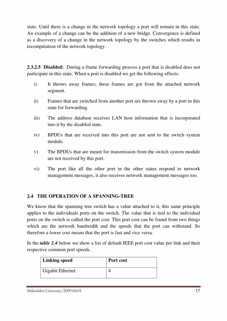
In the table 2.4 below we show a list of default IEEE port cost value per link and their
respective common port speeds.
Linking speed Port cost
Gigabit Ethernet 4

Mälardalen University/2009.04.01 18
Fast Ethernet(100 Mbps) 10
Ethernet( 10Mbps) 100
[22]
Rate of the data Path cost for STP
4 Mbps 250
10 Mbps 100
16 Mbps 62
45 Mbps 39
100 Mbps 19
155 Mbps 14
200 Mbps 12
622 Mbps 6
1 Gbps 4
2 Gbps 3
10 Gbps 2
By now it is reasonable to ask ourselves the question of what use is the port cost to the
switch?. The answer is simply that the switch uses the port cost to find the root port for
each switch in the network. For data traffic to be sent forth across the network all non
root bridges have one root port that is used as their connection. By default have a cost
of zero and they are root ports too.
Figure 2.4 is a description of a network that has three bridges. We have bridge A as
the root bridge because it possesses the smallest MAC address and the reason being
that all the bridge priorities are the same.

Mälardalen University/2009.04.01 19
The network topology above has three important characteristics:
i) The first is the link connecting bridge B to bridge A is 100 Mbps, and the
link connecting bridge C to Bridge A is 10 Mbps.
ii) Segment BC connects Bridge B and bridge C together at 10 Mbps.
iii) Finally a loop arises because of segment BC.
Let’s begin analyzing what happens to this STP because of the creation of this loop by
segment BC. Since this loop exists the STP finds out which links stay in a forwarding
state and which will enter the blocking state. Due to the fact that in this particular
network Bridge A has been elected as the root bridge, it is able to send our BPDUs
with a port cost of zero (0). We know that there is no cost assigned to the ports of the
root bridge; logically its port cost will be zero (0). Port one (1) receives the BPDUs on
bridge B and bridge C. When this BPDUs are got by bridge B what it does is, it will
now add its own port cost to it (those provided by the root bridge). Since the cost
attached to a 100 Mbps port is nineteen (19), the root bridge will be reached by bridge
port 1 with a total cost of nineteen (19+0=19). The connection of port 1 of bridge C is
10 Mbps, therefore the total cost is one hundred for it to get to the root bridge. Every
two seconds BPDUs are passed across the network, this is the time lap by default.
[7][15]
Mälardalen University/2009.04.01 20
As a reminder network one has bridge B and bridge C connected to it. BPDUs are also
transmitted on their interface that is connected to network one. Over the network BC,
bridge B can forward BPDU to bridge C. Bridge B tells bridge C that it can get to the
root bridge with the BPDU it received at a cost of nineteen. After this news gets to
Bridge C, port two’s cost will be added to this value, with computation we see that it
will get to the root bridge at a total cost of one hundred and nineteen (100+19=119)
through port 2. Bridge C now has two alternatives either from port one with a cost of
one hundred to get to the root bridge or via port two with a cost of one hundred and
nineteen. Taking into consideration these two ports we see that bridge C determines its
root port from its lower cost to the root, which logically is port 1 with value of one
hundred. Vice versa bridge B can also receive BPDUs from bridge C over segment
BC. It (bridge C) sends forth BPDU messages to the root bridge of one hundred (100).
When this message gets to bridge B, addition of its cost to the cost of port two
interfaces is carried out by it, knowing that it can get to the root bridge through bridge
C at a total cost of two hundred. Again taking into consideration the two paths, bridge
B will choose port one as the root port, reason still being the lower cost path needed to
get to the root.
2.5 DESIGNATED PORTS WHAT ARE THEY?
In the figure 2.4 above we have found out the root port, it also vital to find out which
ports will be in a blocking or forwarding state too. As it is explained that there are two
possible ways or paths from segment BC to the root bridge; these are one through port
2 on bridge B and another through port 2 on bridge C. Due to this a loop arises. To
prevent this loop, a blocking state must be put into effect in one of these two ports. It
has been shown how this can be done in the figure below: According to article, but
here title will be Figure 2.5:

Mälardalen University/2009.04.01 21
It is known that on each network segment on a spanning tree network, then it must be
able to point out one designated port. This port is known by using BPDUs through
another voting. There are three segments in the figure above;
i) Segment AB
ii) Segment BC
iii) Segment AC
Out of the whole lot of connected bridge ports, one has to be voted as the designated
port through which frames are forwarded on to the network. As mentioned earlier the
winner will be the one which has the lowest port cost. The figure below will show the
traffic path from segment BC to segment AC.
Figure 2.6

Mälardalen University/2009.04.01 22
Now another alternative or method has to be used to determine the designated port
since bridge B and Bridge C have the same port cost to each other. To get the
designated port we will use the MAC addresses. Therefore bridge B will be the
designated port one segment BC since it has the lower MAC address. Port two will be
put in the forwarding state on bridge B. When it has been done with these forwarding
and blocking states, any existing traffic from segment BC will leave the segment
through bridge B.
2.6 CONVERGENCE
When the BPDUs have been transferred to find the root bridge, the root port of each
non root bridge, switch and the network is free of any loop. Our discussion will now
be centred on the functioning of the STP when there is a problem in the network.
When it has been computed the STP topology of a network, BPDUs will be sent forth
by each switch every two seconds. The use of the BPDU messages is to tell the
switches of which connections are functional in the network, and also those that are
non-functional.

Mälardalen University/2009.04.01 23
2.7 VIRTUAL ROUTER REDUNDANCY PROTOCOL (VRRP)
Virtual Router Redundancy Protocol (VRRP) avoids a single point of failure in the
network and provides a Layer 3 redundancy link in a shared segment. It is the best
way to create a fault tolerance network as VRRP is providing an automatic backup to a
router in case of network incidence failure arise. In the network in which the VRRP is
being used, one or more physical routers share similar Virtual IP address. Only one
router can be Master router which is a router that actively performs routing function,
while other virtual routers group are Slave or a Backup routers in the case Master
router becomes unavailable.
However, VRRP is IEEE standard Layer 3 redundancy protocol, and HSRP is Cisco’s
proprietary protocol. Actually VRRP and HSRP have identical functionality of giving
router redundancy protocol. VRRP gives a name of Master router to that router
actively performs routing function while HSRP gives a name of Active router.
In the council’s network, by creating a redundant link between the DLS switches, and
by configuring both switches with the same virtual IP address, the council’s network
can have created a 100 percent reliable link.
-Assuming that the Council’s network can be designed to implement VRRP
Creating a virtual router by configuring and associating the virtual ip address on
each of the four switches’ physical interface that owns a real IP address(es).
The configuration may look likes on the table below
Configuring the master multilayer switch Oldswitch1(config)# router vrrp
-enable the vrrp protocol

Mälardalen University/2009.04.01 24
Oldswitch1(config)#int fa0/1
-assign the interface
Oldswitch1(config-if)#description link to oldswitch2
-description of the link
Oldswitch1(config-if)# ip address ip address
Oldswitch1(config-if)# ip address 192.53.5.1
-ip address of the physical interface -this is just a fake ip address that is used for explanation purpose
Oldswitch1(config-if-)# ip vrrp vrid 1
- The ID of the virtual router
Oldswitch1(config-if-vrid)#owner
-determining the master router
Oldswitch1(config-if-vrid)#ip address virtual ip address Oldswitch1(config-if-vrid)#ip address 192.53.5.1
-This is the virtual router IP address that must be a real IP address configured on the VRID interface on one of the VRRP routers. This router is the IP address Owner and is the default Master.
Oldswitch1(config-if-vrid)#owner priority priority-value -A numeric value that determines a Backup’s preferability for becoming the Master for the VRID. During negotiation, the router with the highest priority becomes the Master. • - The Owner has the highest priority (255); non owner routers can have a priority numeric value from 3 – 254. -If more than one Backups have the same highest priority, the Backup interface which is configured with highest IP address becomes the Master for the VRID.
Oldswitch1(config-if-vrid)# hello-interval 1 It is added one-half second by the router software
default Hello interval (1 second)
Oldswitch1(config-if-vrid)# activate
Activate the HP routing switch’s to participation as a VRRP router. Only enabling the protocol does not activate the routing switch for VRRP unless it is activated the device as a VRRP router after the VRRP parameter is configured.
To configure the rest of the non-owner multilayer switches are almost the same
as owner multilayer switch except few differences which is shown in the table
below:
Configuring all non-master Multilayer’s switches i.e oldswitch2,
newswitch1 and newswitch2. Non_master(config)# router vrrp
-enable the vrrp protocol
Non_master (config)#int fa0/1
-assign the interface
Non_master (config-if)#desc. link to the respective switch
-description of the link
Non_master (config-if)# ip address ip address
Non_master (config-if)# ip address 192.53.5.3
-ip address of the physical interface -this is just a fake ip address that is used for explanation purpose
Non_master (config-if-)# ip vrrp vrid 1 - The ID of the virtual router

Mälardalen University/2009.04.01 25
Non_master (config-if-vrid)#backup
-determining the backup router
Non_master (config-if-vrid)#ip address virtual ip address Non_master (config-if-vrid)#ip address 192.53.5.1
-This is the virtual router IP address that must be a real IP address configured on the VRID interface on one of the VRRP routers. It is also configured to all non-owner router as a virtual IP address.
Non_master (config-if-vrid)#owner priority priority-value
Non_master (config-if-vrid)# hello-interval nr Non_master (config-if-vrid)# activate

Mälardalen University/2009.04.01 26
3. THE FORMULATION OF PROBLEM
How am I going to implement STP in Skinnskatteberg council. Some of the questions
I need to ask myself is how fast can I get this job done, since time is an important
factor I am taking into consideration, because I am not only looking at the fact that this
implementation can be cost effective, but I am considering the time to get this job
done. The main problems are that:
• How does the network in Skinnskatteberg council look like today?
• Which methods are they using presently?
• How will the network be improved after implementation of the STP?.

Mälardalen University/2009.04.01 27
4. ANALYSIS OF THE PROBLEM
Presently, the only way the Skinnskatteberg council can get their network running
again after going down is by manually replacing the DLS switch with a new switch
[37]. For example in a larger network this could be very time consuming to replace the
switches manually. Since the council is growing relatively fast this method can be a
problem in the future. Using a redundant link and STP is preferable and gives an
appropriate solution than theirs. Due to the fact that the council can only get their
network back is by manually replacing the switch that had a problem with a new one.
If single point of failure occurs in the network, every other network related that switch
will be affected.

Mälardalen University/2009.04.01 28
5. METHODS
After having a discussion with Steve Henriksson, the supervisor of the IT department
of the Skinnskatteberg’s council about their network, he was able to give me a valid
description in response to the question I asked him during our discussion. I also asked
him how they dealt with problems arising in the network due to network failures.
After I have got information about which method they use to control the switched
network and how they get back the network running by the time a problem arises. I
gave him a proposal saying that it could be interesting to implement the STP in their
network. I explained to him that the implementation of STP could be better to keep the
switched network alive. Some of the important things that we decided were:-
• How to reorganize the network topology to make the reliable and optimal network and give an access without having the problem in the event that a link in the LAN network goes down or switched network has got an incidental failure.
• We have decided to meet every Wednesday or twice in a month (with set day of the week as Wednesday) to make some completing of information if necessary to the network.
• We have also decided how and when to verify the STP implementation on their network.
The methods used in this thesis is by collecting information from internet such as
documents from HP Microsoft and different Cisco’s web based material that I have got
during my study. Because of the fact that during my study I have only learnt about the
configuration of the Cisco’s systems, I have got a little bit difficulties with how to
configure the HP ProCurve switch. By searching information on the internet how to
configure HP switch, I was able to find all information about a sample of configuration
to the switches such as:
5.1 STP in HP ProCurve Switch versus Cisco Catalyst Switch
Below are explained some of the fundamental configurationally differences between
Hewlett-Packard ProCurve switch and the Cisco Catalyst switch. Both platforms use
different names to describe similar concept.

Mälardalen University/2009.04.01 29
5.1.1 To configure STP on Hp switch 2650
By default, STP is enabled on switches while it is disabled on routing switches.[27]
Configuring the command below enables STP on a routing HP switch:[20]
Switch_2650 (config)#span protocol-version [stp]
Switch_2650 (config)#span
Switch_2650 (config)#spanning-tree priority priority_nr
5.1.2 To configure STP on Cisco catalyst switch 3560
It is possible to force the selection of Switch_3560 as the root switch, by setting the
lowest priority value with this command.
Switch_3560#set spantree root [vlan_nr]
Switch_3560#set spantree priority priority_nr [vlan_nr]
5.1.3 To configure STP per VLAN on cisco catalyst switch 3560
To change command below the default-spanning tree behaviour on a per-VLAN basis
on Cisco catalyst switch 3560.
Switch_3560(config) #spanning-tree vlan vlan_nr priority priority_nr
5.1.4 To Configure PVST+ (Per Vlan Spanning Tree Plus) on Cisco switch
Primary and secondary switch configuration:
• By configuring a switch with this command below, the switch can be the primary root bridge on the segment.
Switch_3560(config) # Spanning-tree vlan vlan-nr root primary
• By configuring a switch with this command below, the switch can be the secondary root bridge or backup root bridge on the segment.
Switch_3560(config) # Spanning-tree vlan vlan_nr root secondary
5.1.5 To Configure Backbonefast and Uplinkfast on Cisco switch
• Due to the fact that the STP convergence time is critical at the event of indirect link failure in the network. By configuring all switches with the command below, the switches enable to have faster convergence time.

Mälardalen University/2009.04.01 30
Switch_3560(config) # Spanning-tree backbonefast
• Besides, to minimize the STP convergence time in the network during the direct uplink failure, all access-layer switches can be configured with the command below.
Switch_3560(config) # Spanning-tree uplinkfast
5.2 EtherChannel
EtherChannel, which is Cisco proprietary, is a port trunking mechanism in the network that offers the administrator the ability to configure that bundling multiple physical Ethernet links into one Ethernet logical link. This mechanism helps to provide load balancing, increasing link speed and automatic failover between switches, routers and servers. By bundling ports with eight active FastEthernet, Gigabit Ethernet or 10 Gigabit Ethernet, an EtherChannel can be created. In the event that a link within the EtherChannel fails, the network traffic which traversed on the failed link is carried by the other functional links within the EtherChannel bundle.[33]
5.3 IEEE 802.3ad Link Bundling
The IEEE 802.3ad Link Bundling is IEEE open standard that provides a link trunking mechanism in a network. IEEE 802.3ad bundles several Ethernet links into a single logical link. This mechanism helps to provide a higher bandwidth and the ability to administer or control the grouped links. IEEE 802.3ad modified its functionality by adding Link Aggregation Control Protocol (LACP) that gives the ability to the network device to send LACP packet to peers to automatically negotiating bundle links together to form a single logical link. [30][36]
5.4 Trunking in Cisco switch and Tagging in HP Switch VLAN trunks have the ability to sustain multiple VLANs between switches. A trunk can be defined as a layer 2 link that runs a specialized trunking protocol between switches. Traffic of multiple VLANs can be transported by trunks over physical links. For a trunking protocol to mark the frame so that it can locate the VLAN connected with it, since the frame is placed unto the trunk link then in this case the frames from just one VLAN must move across a trunk link. To mark out the frame to which a VLAN belongs to, each frame must allocate a VLAN ID.[34][35] In this case now the switch that receives the frame knows from where the frame’s VLAN is originating from and can easily process the frame in accordance. The following takes place on the switch that receives, it takes off the VID when the frame is sent forward onto an access link that is connected with its VLAN.

Mälardalen University/2009.04.01 31
The distribution and access layers of the campus switch block have trunk links that are
used between them. The trunk protocol functions in transporting multiple VLANs
through a single link:
• Inter-Switch Link (ISL): Cisco ISL
• 802.1Q: IEEE standard trunking protocol, 802.1Q is not proprietary and can be
deployed in any Layer 2 device with Ethernet standards-based link.
One of the two processes can occur when a data frame is sent across a trunk link, the
first it is either encapsulated or it is tagged and this depends on the trunking protocol.
The main reason for this process is to give the switch that receives a VID so that it can
identify the VLAN from where the frame is coming from. ISL, which is a Cisco
proprietary trunking protocol, frames is encapsulated before it sends, while IEEE
802.1Q embeds a mark into the original Layer 2 data frame. This is unique to a single
Layer 2 protocol (Ethernet) since it modifies the Layer 2 Ethernet frame by putting in
a mark between two particular fields of the frame and there must be a ‘must known’
about the details on the frame header.
There is no necessitate of Layer 2 protocol while using ISL due to the fact that in ISL
the original layer 2 frame is fully encapsulated and not disfigured. Data frames can be
carried from different layer 2 media types.
There are two devices we are going to mention that can exist together without conflicts
on the same network. These devices are the IEEE 802.1Q compliant devices and the
legacy/untagged VLANs, but a separate link is needed for legacy/untagged VLANs.
The 802.1Q tagged VLANs are able to add up several VLANs into one link. Different
ports in 802.1Q-compliant devices must be used to link diverse VLANs to non-802.1Q
devices.[34][35]

Mälardalen University/2009.04.01 32
6. SOLUTION TO THE PROBLEM
In a switched LAN network, to protect against network failure, is very important
providing more than one path to forward and/or receive a data from source to
destination [10]. Even if having a redundant links are advantageous, it can have
harmful side effect and causing a switching loops[11]. But by using the STP can keep
from this looping problem. With the implementation of the STP, a single point
network failure in one part of the network does not have an impact in the other areas,
thus we can solve it while the other network areas continue to function normally.
Below is the figure showing the redesigned distribution layer switched network
topology and after the implementation of the STP in the Skinnskatteberg council
network:

Mälardalen University/2009.04.01 33
6.1 Creation of Redundant Link
The council has bought two HP ProCurve 2650 switches. Redundant paths are created
between the new switch and the old switch from Skinnskatteberg council and another
link is created between the old switch and the new switch from the school network.
By creating a link between the old switch from Skinnskatteberg council network and
the old switch from the school network, at the same time another link is created
between the new switch from Skinnskatteberg council network and the new switch
from the school network. These paths are produced to provide a reliable and fault
tolerance network. At this point a redundant link is now created between the
Skinnskatteberg council network and the school network. This is better explained
from the figure 5.1 below, this figure 5.1 shows only the concerned part of the area on
the network:
Figure 6.1 Better Explanation of the Created Redundant Link between the council and
the school. This figure shows only the concerned part of the area on the network.

Mälardalen University/2009.04.01 34
6.2 USING STP TECHNIQUE
6.2.1 Selection of Root Bridge
As we know the switch priority default value is 32768. But this time we decide to
change the priority 1 manually and making the Old switch 1 from Skinnskatteberg
council network segment as the root bridge. The configuration used to elect a root
bridge is:
Switch_2650# configure terminal
Switch_2650(config)#hostname Old_switch1_skbg
Old_switch1_skbg (config)#span protocol-version stp
Old_switch1_skbg (config)#span
Old_switch1_skbg (config)#spanning-tree priority 1
6.2.2 Selection of Port Role
• After the root bridge is elected by the administrator the switches start to choose
which switch ports forward data and which switch ports block data by using the
STP algorithm. [7]
• The three parameters that the switch uses to choose a port role are, the first is
lowest path cost, the second is lowest sender BID, and the third is the lowest
sender port ID. First the switch looks at the first parameter which is the path
cost, it does these computations from the speed of the link and the number of
links that the BPDU have travelled through. Therefore the ports that have the
lowest cost are qualified to be put in the forwarding mode and the rest continue
in the blocking mode. [6] If all ports have the same path cost then the switch
looks at the second parameter which is the lowest sender BID. If all switches
still have the same sender BID the switch looks at the third parameter which is
the lowest sender port ID. [7][9][13]

Mälardalen University/2009.04.01 35
7. RESULT
The result was very successful as I expected from the beginning. By buying two
pieces of HP ProCurve 2650 switches have been created a redundant link to the new
network topology. We (I and Steve, the supervisor of the IT department) were able to
redesign the network. After that we started with the STP configuration to all switches
by enabling the STP mode and then we configured the spanning tree protocol to all
switches and tried to see if all switches are running STP and have a relevant port state.
Of course, there was no obstacle with the configuration, the implementation and that is
why the maximum result was achieved. The next we did was that we tried to see if the
root bridge was chosen and all ports had the appropriate states according to the STP
mechanism. This proved to be successful as all ports in different switches had the right
port state position on their port state.
By disconnecting one of the redundant links from the root bridge on the switched
network, we tried to see if any change had occurred on the switches’ port states. Yes,
there were changes and a modification has occurred on the switched network topology.
The switch port with the blocked state changed its status to forwarding state. The
entire network topology has been re-established to the new topology network. As a
link failure had occurred in the network all switches received the topology change
notification (TCN) BPDU, therefore, all switched has reconfigured the active topology
according to the TCN BPDU. After that a new root bridge was elected by exchanging
BPDU packet on the network. All switches ports were exchanging their port state by
using the new BPDU packet’s information.
8. DISCUSSIONS
During this thesis study about the Implementation of Spanning Tree Protocol on the
Skinnskatteberg’s council, I have encountered some difficulties regarding configuring
HP ProCurve switches. Due to the fact that I have only learnt about the Cisco’s
systems configuration CLI (command-line interface), there were going to be inevitable
difficulties with HP devices. But this knowledge is enough to provide the base, with
some effort and research, to configure any device regardless of the device
manufacturer.
There can be some limitations regarding the capabilities on the type of device used
depending on the manufacturer. HP ProCurve switch and Cisco switch provide the
following limitations below.

Mälardalen University/2009.04.01 36
• Both HP ProCurve and Cisco devices support standard STP as described in the
IEEE 802.1D specification. But use a different CLI to configure the respective
devices. Even with such CLI differences, the goal of what standard SPT can
result remains the same. Cisco devices support more advance quality of service
and features than what HP ProCurve devices offer.[25][9]
• HP ProCurve platform does not support QoS implementation on the network,
such as planning, prioritizing traffic and bandwidth allocation.[23]
• HP ProCurve platform does not have support for configuration that enables
faster failover, greater redundancy and allows for traffic load sharing across
uplinks such PVST+, BackboneFast and CrossStack UplinkFast.[23]
STP is not the only protocol which offers loop-free in a redundancy network. There
are other protocols which provide with a much faster convergence time than STP.[8]
One alternative to STP is the IEEE Layer 3 protocol VRRP that provides a faster
convergence time and a much better security by providing functions such as:
• When network failover occurs, the convergence time that STP provides is much
slower when compared with VRRP. STP has a convergence time 50 seconds
while VRRP’s convergence time can even be adjusted to milliseconds.[30]
VRRP gives the administrator the ability to manually manipulate the
convergence time. [30][31]
There is another alternative method to STP which is called routed port where the
switch’s physical interface port is converted from a Layer 2 switchport to a Layer 3
router physical interface that behaves like an interface on a router. By configuring the
routed port with IP address, the Layer 3 connectivity is created between the switches
and traffic can be routed between adjacent switches. This method is very effective and
can converge faster and yet still very simple to implement it. [16] [28][29]
Routed port works by configuring “ip routing” command in global configuration
mode, and “no switchport” command on an interface mode on multilayer switch. This
enables the switch port to function as an interface on a router. To work with this routed
port, the topology change must be done by creating a redundant links between the
distribution layer switches and access layer switches. Having this done, loops can be
prevented by directing traffic on the desired route and thus blocking the other route
until the preferred route goes down.[16] [28][29]

Mälardalen University/2009.04.01 37
9. LIMITATION
Due to the fact that I had only ten fulltime working weeks to complete this thesis, I
have only been able to cover some part of the network of Skinnskatteberg council,
that is I was not able to connect my outside the switched network area.
10. PROPOSAL FOR CONTINUATION OF STUDY
As a proposal for continuation of study more work can be done on the implementation
of wireless Spanning Tree Protocol. Another interesting topic of work could be the
Rapid Spanning Tree Protocol for companies that are willing to invest more into their
IT department.

Mälardalen University/2009.04.01 38
References:
[1] http://ieeexplore.ieee.org/stamp/stamp.jsp?arnumber=04232939 , last visited on 27th of November
2008 at 15:17.
[2] http://en.wikipedia.org/wiki/Spanning_tree_protocol last visited 09th of October 2008 at 19:11.
[3]http://www.cisco.com/en/US/tech/tk389/tk621/technologies_configuration_example09186a008009
467c.shtml , last visited 09th of October 2008 at 20:00.
[4]http://en.wikipedia.org/w/index.php?title=Spanning_tree_protocol&action=edit§ion=3, last
visited 09th of October 2008 at 19:11.
[5]http://www.mdh.se/netcenter/cisco/ccnp/CCNP3_v50_en/CCNP3_v50_en/ch3/main.html, last
visited 09th of October 2008 at 19:11.
[6] http://www.ccprep.com/resources/cc-whitepapers/june/Paper%200501%20-
%20Spanning%20Tree.pdf the last visited 09th of October 2008 at 19:41.
[7]http://www.mdh.se/netcenter/cisco/ccnp/CCNP3_v50_en/CCNP3_v50_en/start.html , last visited
3rd of December 2008 at 16:27.
[8]http://www.basautomation.com/ExtVol7N3.htm, last visited 8th December 2008 at 14:27.
[9] http://searchnetworking.techtarget.com/tip/1,289483,sid7_gci524098,00.html , last visited 8th
December 2008 at 15:23.
[10] http://www.spirit.com/Network/net0503.html , last visited 17th December 2008 at 15:55
[11]http://www.mdh.se/netcenter/cisco/ccna/1/3_1_1/en-knet-
311053022401441/ccna3theme/ccna3/CHAPID=knet-
1061921696348/RLOID=null/RIOID=null/knet/311053022401441/chapterframeset.html, last visited
on 16th December 2008.
[12]http://www.cisco.com/en/US/docs/switches/lan/catalyst6500/ios/12.1E/native/configuration/guide/
spantree.html , last visited on 13 of January 2009 at 15:15.
[13]http://www.cisco.com/en/US/tech/tk389/tk621/tk5/tsd_technology_support_sub-
protocol_home.html, last visited on 13 of January 2009 at 15:19
[14]http://www.javvin.com/protocolSTP.html, last visited on 13th of January 2009 at 15:23.
[15] http://etutorials.org/Networking/Lan+switching+first-
step/Chapter+7.+Spanning+Tree+Protocol+STP/, last visited on 13th of January 2009 at 16:31.
[16] http://www.petri.co.il/csc_preventing_network_loops_with_stp_8021d.htm, last visited on 20th
of January 2009 at 14:50.
[17]http://www.ccnacertificationguide.com/Root_Bridge_Election.php, last visited on 22th of January
2009 at 13:44.

Mälardalen University/2009.04.01 39
[18] http://adams.kwangwoon.ac.kr/lecture2008/fall/chap15.ppt#426,11,TransparentBridges:
Spanning Tree, last visited on 22th of January 2009 at 15:40.
[19]http://www.mdh.se/netcenter/cisco/ccnp/CCNP3_v50_en/CCNP3_v50_en/ch3/main.html, last
visited on 17th of March 2009 at 11:00.
[20]http://www.tek-tips.com/viewthread.cfm?qid=1221775&page=1, last visited on 18th of March
2009 at 11:39 .
[21]http://www.informit.com/library/content.aspx?b=CCNP_Studies_Troubleshooting&seqNum=64,
last visited on 18th of March 2009 at 11:45
[22]http://www.tecnocael.it/ftp/docs/ProCurve_Cisco.pdf, last visited on 18th of March 2009 at 11:53.
[23]http://www.cisco.com/global/EMEA/sitewide_assets/pdfs/engage/2950_vs_hp.pdf, last visited on
23th of March 2009 at 16:20.
[24]http://www.sincompromisos.com/Documentos/IP/cisco-3560/MST.pdf, last visited on 18th of
March 2009 at 14:43.
[25]http://www.cisco.com/en/US/tech/tk389/tk621/technologies_configuration_example09186a00800
9467c.shtml#maintask1, last visited on 23th of March 2009 at 02:16.
[26]http://www.cisco.com/en/US/docs/switches/lan/catalyst6500/ios/12.1E/native/configuration/guide/
stp_enha.html#wp1022412, last visited on 23th of March 2009 at 01:42.
[27] ftp://ftp.hp.com/pub/networking/software/59692338_4.pdf , last visited on 25 Feb. 2009 at 11.24.
[28] http://www.ciscopress.com/articles/article.asp?p=358549&seqNum=4, last visited on 30 of
March 2009, at 13:33.
[29]http://www.cisco.com/en/US/docs/switches/lan/catalyst3550/software/release/12.1_13_ea1/config
uration/guide/swfallbk.html, last visited on 30 of March 2009, at 14:23.
[30]http://www.tml.tkk.fi/Opinnot/Tik-
110.551/1998/papers/03FaultTolerance/fault.html#4.3.1.%20VRRP, last visited on 29th of March, at
14:23.
[31]http://www.hp.com/rnd/support/manuals/pdf/release_06628_07110/Bk2_Ch12_VRRP_VRRPE.p
df, last visited on 28th of March 2009, at 10:26.
[32]http://www.networkdictionary.com/protocols/vrrp.php, last visited on 28th of March 2009, at
11:26.
[33]http://kb.vmware.com/selfservice/viewContent.do?externalId=1004048&sliceId=1, last visited on
28th of March 2009, at 12:00.
[34]http://en.wikipedia.org/wiki/Trunking, last visited on 27th of March 2009, at 18:31.
[35]http://en.wikipedia.org/wiki/Port_trunking, last visited on 27th of March 2009, at 18:33.
[36]http://www.cisco.com/en/US/docs/ios/12_2sb/feature/guide/sbcelacp.html, last visited on 28
March 2009, at 18:02
Mälardalen University/2009.04.01 40
[37] Steve Henriksson, IT Ansvarig, Skinnskatteberg Kommun. November 2008.