Embed Size (px)
Citation preview
1
Implementation of IS-IS routing protocol for the eXtensible Open Router Platform (XORP)
Group Report
Group Members Bitao Sun
Hongyi Li
Ling Zhen
Kang Tang
Xin Xiong
Supervisor Professor Mark Handley
September 2nd, 2005
2
Acknowledgements The group would like to express our sincere appreciation to our supervisor
Professor Mark Handley, for the enlightening advice and assistance as well as the
continuous confidence and encouragement he has been giving us throughout the
project, especially when we were faced with difficulties and feeling frustrated. We
would not have achieved a success without his great help and guidance.

3
Table of Contents Chapter One: Introduction .............................................................................................5
1.1 Report Overview ..........................................................................................5 1.2 Introduction to the project ............................................................................5
Chapter 2: Background ..................................................................................................7 2.1 Overview of the IS-IS routing protocol ............................................................7
2.1.1 Link State Routing Protocol....................................................................7 2.1.2 IS-IS routing protocol .............................................................................8
2.2 XORP router platform.....................................................................................13 2.2.1 XORP Design Philosophy.....................................................................13 2.2.2 Architecture of XORP...........................................................................14 2.2.3 Other Features of XORP.......................................................................17
Chapter 3: Objectives, Scope and Requirements.........................................................19 3.1 Objectives and scope.......................................................................................19 3.2 Requirements Analyses...................................................................................19
3.2.1 Routing Functions.................................................................................19 3.2.2 XRL interfaces ......................................................................................20 3.2.3 Modification of the FEA.......................................................................20
Chapter 4: Design and Implementation .......................................................................22 4.1 Define the XRL interface...........................................................................22 4.2 System Architecture Design .......................................................................22
4.2.1 Preliminary System Design..................................................................23 4.2.2 Final System Architecture.....................................................................27 4.2.3 Discussion of the System Architecture Design Issues ..........................31
4.4 Design and Implementation of Major components.........................................33 4.4.1 PDU Encoding and Decoding...............................................................33 4.4.2 Modifications to the FEA .....................................................................35 4.4.3 Circuit & CircuitIO...............................................................................36 4.4.4 CircuitManager & XrlCircuitManager .................................................41 4.4.5 Link State Database ..............................................................................42 4.4.6 Shortest-Path-First (SPF) Calculation...................................................47 4.4.7 XrlRibNotifier.......................................................................................48
Chapter 5: Testing and Evaluation ...............................................................................51 5.1 Set up testing environment..............................................................................51 5.2 Unit Testing and Integration Testing...............................................................53
4
5.2.1 Packet Encoder and Decoder ................................................................53 5.2.2 Circuit ...................................................................................................54 5.2.3 LSD & SPF ...........................................................................................56 5.2.4 XORP Integration Tests ........................................................................58
5.3 Overall System Testing ...................................................................................61 Chapter 8: Project Management...................................................................................63
8.1 Project Management Plan ...............................................................................63 8.2 Work Breakdown ............................................................................................64 8.3 Team Organisation ..........................................................................................65 8.4 Monitor and Control .......................................................................................67 8.5 Risk Management ...........................................................................................68
Chapter 9: Future Work and Conclusion......................................................................69 9.1 Future Work ....................................................................................................69 9.2 Conclusion ......................................................................................................69
Bibliography ................................................................................................................71

5
Chapter One: Introduction
1.1 Report Overview
This report serves as the major documentation of our project -- an implementation
of the Intermediate System to Intermediate System routing protocol based on the
eXtensible Open Router Platform (XORP). It provides descriptions and analyses of
our development process so as to help the readers understand the project in both
technical and management aspects.
The whole report is organised as several sections. The first part (Chapter 1&2)
gives an introduction to the background of the project, including the main features of
the IS-IS routing protocol as well as the XORP platform it is to be implemented on,
which is essential for understanding the rest of the report. Then the objectives, scope
and requirements of the project are identified in Chapter 3. Chapter 4 presents the
design and implementation of the overall system and major individual components
respectively. Not only the design choices and decisions, but also the reasons behind
them are discussed. The following chapter is about the testing and evaluation of the
project, which gives critical assessment on how each module and the system as a
whole work, in comparison with the objectives of the project set up at the beginning.
The rest of the report discusses the future work that can be done to further complete
and improve the project, and the project management approaches adopted by the
group.
1.2 Introduction to the project
Many researchers in the network community are facing a difficult problem that
some of their experiments can only be carried out in simulation environments instead
of real networks. For example, it is almost impossible to evaluate a new routing
protocol, because the commercial router platforms consisting the Internet provide
neither open source router software, nor open API to researchers to deploy the new

6
protocol in real networks. The design of the eXtensible Open Router Platform (XORP)
is aimed to provide a solution for this problem. To fulfil such a goal, it is necessary for
XORP to be both a stable deployment platform that can be used in production
networks and be an extensible research platform so that researchers can introduce new
protocols or improve existing protocols in the networks. As a result, the design of
XORP focuses on three main goals: extensibility, performance and robustness. How
these goals are achieved will be introduced in next chapter along with the architecture
of XORP.
Currently, XORP provides a set of routing protocol implementations, an
extensible programming API, and configuration tools. The supported protocols are
BGP, RIP, PIM-SM, and IGMP/MLD. IPv4 and IPv6 are both supported. While a
reasonably complete port of John Moy's OSPFd (on FreeBSD) to the XORP
environment exists, it has not been well enough tested to know if it works or not, and
an OSPF implementation specifically for XORP will be produced in the future.
Compared to two other existing open source router software Zebra and Quagga,
which are licensed under the GPL which imposes certain constraints on users, XORP
is licensed under a BSD-style license, which permits people to freely use it, customize
it, make their own product out of it, etc. This may be important to commercial users
and may makes XORP to be more widely used in the real world.
The Intermediate System to Intermediate System Routing Protocol is a link state
routing protocol which has a lot in common with OSPF. Although OSPF is the
primary routing protocol for IP, IS-IS routing has become increasingly popular
widespread usage among Internet Service Providers in recent years. IS-IS enables
very fast convergence with large scalability, and It is also a very flexible protocol and
can been extended to incorporate many new features. Therefore, it is definitely
necessary for XORP to provide support for the IS-IS routing protocol. Our project is
based on such a motivation and is an initial attempt to provide such support.

7
Chapter 2: Background
2.1 Overview of the IS-IS routing protocol
2.1.1 Link State Routing Protocol
Since IS-IS is a link state routing protocol, the basic ideas and operations of
general link state routing are first introduced briefly.
Link-state routing and Distance Vector routing are two main categories of
dynamic routing protocols. In Distance Vector routing, each router observes its
distance to every other router in the domain and transmit this information to its closest
neighbours, while Link-state routing works by having a router inform every other
router in the domain about its closest neighbours. Link-state routing provides greater
flexibility and sophistication than Distance Vector routing, and avoids the major
problems of Distance Vector routing such as split horizon and counting to infinity.
The basic principles of link state routing are outlined as follows:
1. In link state routing, each router exchange Hello packets and establishes
an adjacency with each of its neighbours.
2. Each router constructs a Link State Packet (LSP) based on its adjacencies
and transmits it to each neighbour. LSP contains a list of the router’s
neighbours, the state of the link between the router and each neighbour,
and the metric cost of the router’s interface to the link. Each router in turn
forwards the LSPs it receives to each of its own neighbours.
3. Each router stores in a local Link State Database a most recently copy of
all the LSPs it has received.
4. Each router now has a complete graph of the network topology stored as
the Link State Database. Based upon this information, each router
computes the shortest path to each destination using Dijkstra algorithm,
and enters this information into the route table.

8
2.1.2 IS-IS routing protocol
IS-IS is initially designed as the routing protocol for the ISO’s Connectionless
Network Protocol (CLNP) and is described in ISO 10589. Since at that time, it was
believed that TCP/IP was an interim protocol suite that would eventually be replaced
by the OSI protocol suite, to support this predicted transition, an extension to IS-IS –
Integrated IS-IS for IP and Dual environments was proposed and was described in
RFC 1195. The purpose of Integrated IS-IS was to provide a single routing protocol
with the capabilities of routing both Connectionless-mode Network Service (CLNS) –
the network layer protocol of CLNP and IP, in contrast with an alternative method
known as “Ships in the Night”, which makes use of completely independent routing
protocols for each of the two protocol suites.
However, since the OSI protocol suite did not end up getting widely used as
TCP/IP, IS-IS is actually used only as an IP routing protocol. Therefore, both the
discussions here and our implementation are based on IP-only environments.
1. IS-IS Hierarchical routing
In order to support large routing domains IS-IS routing has been organized
hierarchically. A routing domain can be administratively divided into areas. Routing
inside an area is referred to as Level 1 routing and between the areas as Level 2
routing. The following graph illustrates the idea of IS-IS areas. An intermediate
system can be a level 1 (L1) router, a level 2 (L2) router, or both (L1/L2).
A L1 router knows only the topology in its own area, and it has a L1 link state
database with all the information for intra-area routing. It uses the closest L2 router in
its own area to send packets out of the area. A L2 router may have neighbors in the
same or in different areas, and it has a L2 link state database with all information for
inter-area routing. L2 routers know about other areas but will not have Level 1
information from its own area. A L1/L2 router may have neighbors in any area. It has
both a L1 and a L2 link-state database for intra-area and inter-area routing. A L1/L2
router runs two SPF calculations and may require more memory and processing as a

9
result.
Figure 2-1. IS-IS Areas
2. Addresses used in IS-IS
Although IS-IS is now primarily used for IP routing, it still has to use the OSI
network-layer address known as NSAP which is defined for CLNS packets. A NSAP
address consists of a number of different parts that are organized hierarchically. But
for IP-only routing, where routers normally only have TCP/IP addresses, a valid OSI
style address can be and should be algorithmically generated from existing IP address
and Autonomous System number assignments. In such cases, the useful fields in an
OSI address are:
-- The Routing Domain field: the AS number
-- The Area field: assigned by the authority responsible for the routing domain,
such that each area in the routing domain must have a unique Area value;
-- The System ID field: it is recommended to use either an IEEE 802 48 bit station
ID (MAC address) or to use the value hex “02 00” prepended to an IP address
of the router. Here we choose to use an IP address to identify a IS-IS system.
3. IS-IS Functional Organisation
One of the primary reasons for having a layered network architecture like the OSI
model is so that the functions of each layer can be independent from the layer below.
The network layer, for example, must adapt to many types of data links or
10
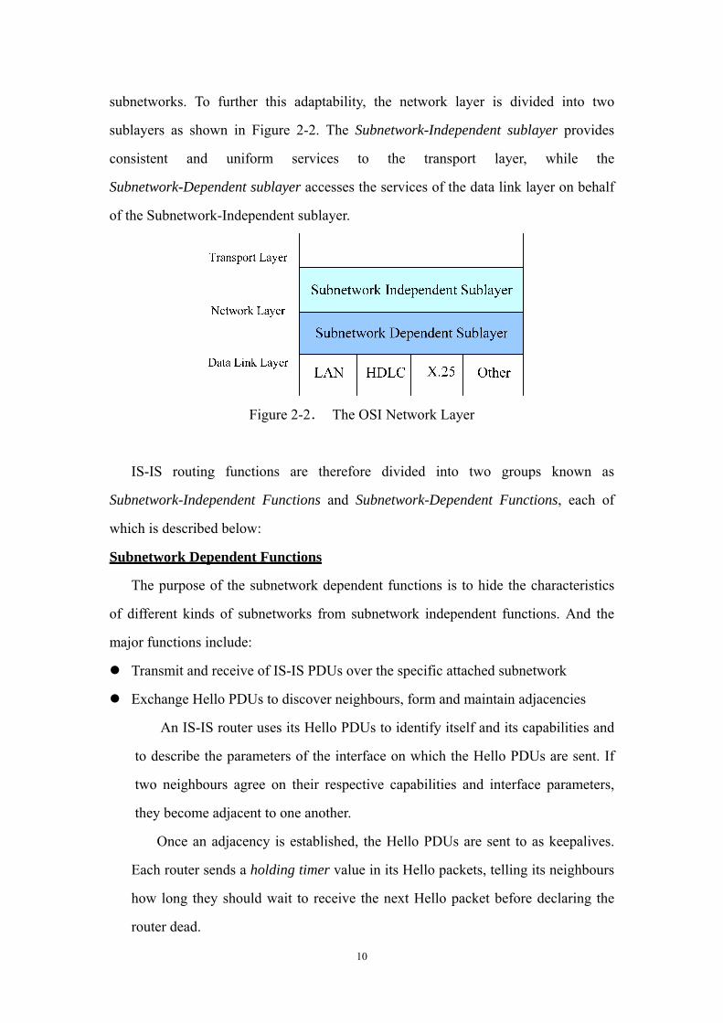
subnetworks. To further this adaptability, the network layer is divided into two
sublayers as shown in Figure 2-2. The Subnetwork-Independent sublayer provides
consistent and uniform services to the transport layer, while the
Subnetwork-Dependent sublayer accesses the services of the data link layer on behalf
of the Subnetwork-Independent sublayer.
Figure 2-2. The OSI Network Layer
IS-IS routing functions are therefore divided into two groups known as
Subnetwork-Independent Functions and Subnetwork-Dependent Functions, each of
which is described below:
Subnetwork Dependent Functions
The purpose of the subnetwork dependent functions is to hide the characteristics
of different kinds of subnetworks from subnetwork independent functions. And the
major functions include:
Transmit and receive of IS-IS PDUs over the specific attached subnetwork
Exchange Hello PDUs to discover neighbours, form and maintain adjacencies
An IS-IS router uses its Hello PDUs to identify itself and its capabilities and
to describe the parameters of the interface on which the Hello PDUs are sent. If
two neighbours agree on their respective capabilities and interface parameters,
they become adjacent to one another.
Once an adjacency is established, the Hello PDUs are sent to as keepalives.
Each router sends a holding timer value in its Hello packets, telling its neighbours
how long they should wait to receive the next Hello packet before declaring the
router dead.

11
LAN Designated IS
In order to reduce the amount of routing traffic, a mechanism known as
Designated IS is used on broadcast networks. As shown in figure 2-3, rather than
having each router connected to the LAN advertise an adjacency with every other
router on the LAN, the LAN itself is considered as a router and is called a
“pseudonode”. A Designated IS (DIS) is elected based on an administratively set
priority value. Each router, including the DIS, advertises a single link to the
pseudonode, and the DIS also advertises a link to all of the attached routers on
behalf of the pseudonode.
Figure 2-3. LAN Designated IS and pseudonode
Subnetwork Independent Functions
The subnetwork independent functions can be divided into four processes as
shown in figure 2-4: the Update process, the Decision process, the Forwarding
process and the Receiving process. The last two processes are responsible for the
transmission and reception of PDUs and are of little relevance to IP packets; therefore
we basically do not need to worry about them.

12
Figure 2-4. Four processes in the Subnetwork Independent Functions
The Update Process
The Update Process is responsible for generating and propagating Link State
information reliably throughout the routing domain, as well as maintaining its Link
State Database (LSD). An LSP holds information about the adjacencies and their
metric values seen by the system that originated the LSP, and since IP routes to IP
subnets, it also contains the IP reachability information (IP address + subnet mask)
reachable by the system.
A system generates its own LSPs periodically and when topological changes or
system management actions happen, for example, when an adjacency goes down or
when the metric of an interface changes. LSPs are propagated throughout the domain
by flooding, in which each router propagates to all its neighbour routers except the
neighbour from which it received the LSP.
IS-IS uses Sequence Number PDUs (SNPs) both to assure the reliable
propagation of LSPs and to maintain LSD synchronisation. On a point-to-point
subnetwork, a router uses a Partial SNP (PSNP) to explicitly acknowledge each LSP it
receives. On broadcast networks, LSPs are not acknowledged by each receiving router.
13
Instead, the DIS periodically multicasts a Complete SNP (CSNP) that describes every
LSP in its link state database. When a router receives a CSNP, it compares the LSPs
summarised in it with those in its own LSD. If the router has an LSP that is missing
from the CSNP or a newer instance of an LSP, the router multicast the LSP onto the
network; If the router’s LSD does not contain a copy of every LSP listed in the CSNP
or if the LSD has an older instance of some LSP, it multicasts a PSNP containing the
LSP it needs, and the DIS responds with the appropriate LSP(s).
The Decision Process
The decision process uses the information in the LSD built by the update process
to calculate a shortest path tree, which is then used to construct a forwarding database
or route table. Dijkstra computations are run separately for L1 and L2 LSDs, and
separately for each supported routing metric within a level. The Dijkstra computation
calculates routes to each distinct IP reachability entry, which can be treated in much
the same manner as an OSI end system.
2.2 XORP router platform
Since our implementation of IS-IS routing protocol is to be based on the XORP
router platform, it is essential to have a good understanding about the architecture of
the XORP, and especially the components which are relevant to our development.
This section gives a description about these issues.
2.2.1 XORP Design Philosophy
As mentioned before, there are three major goals which XORP set out to achieve:
extensibility, performance and robustness. To achieve extensibility and robustness, the
functionalities in XORP are separated into independent modules and run in different
UNIX processes, with well-defined APIs between them. For example, each different
routing protocol runs as an individual process. In this case, even if a certain routing
process crashes, it will not bring down the whole system, and the router will still be
able to perform most of its functionalities with other processes running properly.

14
However, a result of such a design is that the system performance would be affected
by the need of carrying out inter-process communications. Thus the inter-process
communication mechanism is carefully designed so that the cost is minimised.
2.2.2 Architecture of XORP
The figure below shows the system architecture of XORP, which can be divided
into two subsystems. The higher-level (“user-space”) subsystem consists of the
routing protocols and management mechanisms. The lower-level (“kernel”) provides
the forwarding path, and provides APIs for the higher-level to access. User-level
XORP uses a multi-process architecture with one process per routing protocol, and a
novel inter-process communication mechanism known as XORP Resource Locators
(XRLs). XRL communication is not limited to a single host, so XORP can potentially
run on multiple and distributed systems.
Figure 2-5. XORP Process Model
Management Processes
15
On top level, the four processes IPC finder, router manager, CLI (Command Line
Interface) and SNMP is for management purposes. The router manager is responsible
for starting all the processes of the router in an order that is based on their
dependencies, as well as monitoring their status, and together with the CLI provides
an interface for administrators to configure the router. IPC finder is a component for
inter-process communications.
FEA: Forwarding Engine Abstraction
At the very bottom of XORP user-space is the Forwarding Engine Abstraction,
which as its name suggests, provides a uniform interface to the underlying forwarding
engine and hides the variations between different platforms from other user level
processes. For example, these processes do not need to worry about whether the
underlying router is actually just a single machine or a set of distributed machines.
The FEA provides four different functions: interface management, forwarding
table management, raw packet I/O and TCP/UDP socket I/O. Important to routing
processes, including IS-IS is its interface management function. The FEA can learn
from hardware the state and useful attributes of configured interfaces. Useful
attributes include the whether the interface is a broadcast interface or a point-to-point
interface, its Mac address, the IP Subnets connected to it and so on. When there are
configuration requests from user input, the router manager passes them on for the
FEA to execute accordingly. Processes can register with the FEA to be notified of
changes in interface configuration. The registered processes are notified of changes,
and may query the FEA on the receipt of an update notification to determine the
change that occurred. These notifications are primarily of interest to routing protocols
since they need to know the up-to-date state of each interface.
The packet I/O functions can also be useful to routing processes. For example,
RIP makes use of the TCP/UDP socket I/O to send and receive packets. When it
wishes to send a packet, the RIP process just hands the packet to the FEA along with
an indication of which interface it should be sent on; for packet reception, the routing
process registers with the FEA about what types of packets it is interested in, and the
FEA will deliver such packets to it when received. However, the packets IS-IS uses to

16
exchange information are raw Ethernet packets, which the FEA does not have any
existing interface to handle at the present. Therefore, we need to take this into account
when designing the system, and need to decide a way for packet transmission and
reception.
RIB: Routing Information Base
The RIB receives and stores routing information from all the routing protocols
running on a XORP router, i.e. the routes calculated by different protocols according
to their own algorithm. When it happens that there exist multiple different routes to
the same destination subnet, the RIB is responsible for deciding which route should be
used based on some administratively configured parameter. The RIB then propagate
the winning route to the FEA, and hence on to the actual forwarding engine.
Routing Processes
BGP4+, OSPF and RIP are the unicast routing protocols that XORP supports right
now, and IS-IS is the component we aim to implement in this project. Since these
processes do not directly communicate with each other, other routing protocols are
actually of little relevance to IS-IS implementation. However, the RIP module does
play an important role in the development process for we refer a lot to its internal
architecture and its code, especially at the early stages of the project. (reasons: general
similarity as routing protocols: exchange packets and maintain database; interaction
with other XORP components; utilization of the XORP library functions and useful
mechanisms; coding style.) Multicast routing processes are totally irrelevant.
XORP Inter-process communications
The separate processes of a XORP router communicate with one another using an
asynchronous remote procedure call mechanism, which is realized by using XORP
Resource Locators (XRLs). XRLs essentially represent inter-process procedure calls
along with their arguments. On a XORP router, each process provides one or more
interfaces that other processes can invoke. In another word, each process is capable of
handling XRL calls. Such a process is termed as a “target”. The IPC finder mentioned
before acts as an inter-process mediator. It knows the location of each XRL target, and
it is responsible for directing XRL calls to the right target. The advantage of this

17
mechanism is that each of the XORP components only need to register with the IPC
finder, but does not need to know explicitly the location of all other processes, or how
to communicate with them. An XRL may be represented in a human readable form
that allows for easy manipulation with editing tools and invocation from the command
line during development. The XORP libxipc library provides a program “call_xrl” for
developers to perform XRL calls on command line or using simple scripts. (give an
example of XRL human-readable form and explain; XRL router)
2.2.3 Other Features of XORP
1. Programming Language
XORP is primarily implemented in C++ because of its object orientation and
good performance. Besides, C++ provides a lot of powerful features that may make
the code simpler. For example, extensive use of C++ templates allows common
source code to be used for both IPv4 and IPv6, with the compiler generating efficient
implementations for both.
2. Event-driven model
Each XORP process adopts a single-threaded event driven programming model
[ref:xorp-nsdi]. One reason is that an application such as a routing protocol, where
events affecting common data come from many sources simultaneously, would likely
have high locking overhead. Additionally, as XORP is an open-source platform that
welcomes developers of all levels to make extensions, having a single-threaded design
is much better and easier for new programmers like us than using a multi-threaded
design which is not only hard to understand but also more error-prone.
Each XORP process has a single event loop. Events are generated by timers and
file descriptors; callbacks are dispatched whenever an event occurs. The libxorp
library provides several classes useful for using the event loop to handle events:
EventLoop, XorpTimer and XorpCallback.
3. Facilities provided by XORP libraries
XORP provides a large set of common C++ class libraries that would greatly

18
simplify the development of code. In the libxorp library, there are a set of classes for
storing and manipulating IPv4 and IPv6 addresses, IP subnet addresses, MAC
addresses and routing next-hop information; a file debug.h providing facility for
debug messages generation; and a template class ref_ptr, a strong reference class
which maintains a count of how many references to an object exist and releases the
memory associated with the object when the reference count reaches zero.

19
Chapter 3: Objectives, Scope and Requirements
3.1 Objectives and scope
The primary goal of the project is to provide a functional IS-IS routing protocol
implementation for the XORP platform. Considering the time constraints and the
nature of the project, it is not very realistic for the project to provide a complete
implementation that includes all the functionalities defined by the RFC specifications,
and can be actually deployed in the real world. Therefore, we have decided that we
aim to implement the core functionalities which are required by the basic operations
of the protocol, and other optional functionalities such as authentication and partition
repair will not be included in the project.
Another requirement indicated by this goal is that the IS-IS implementation need
to be able to correctly communicate with other processes on the XORP platform when
necessary. As mentioned before, this requirement mainly includes the following
aspects:
Obtain information about interface state from the FEA.
Send and receive packets via the FEA.
Send routes computed by the decision process to the RIB.
Initially, there is another goal of the project, which is to implement a simulation
framework on which we can test the IS-IS implementation. However, as our
development progresses, we decided that there would not be enough time for us to
provide this simulation framework. Therefore, we modified our initial goals and
decided to concentrate on implementing a functional IS-IS routing process.
3.2 Requirements Analyses
3.2.1 Routing Functions
The routing function requirements are clearly defined in the specifications, which

20
mainly include:
Exchange of IS to IS Hello packets
Neighbour adjacency building and maintaining
LAN Designated IS election
LSP generation and propagation
Link State Database building and maintaining
SPF route calculation
3.2.2 XRL interfaces
Every process in XORP provides one or more XRL interfaces for other processes
to send requests to it. For routing processes, it is necessary to provide some methods
so that the protocol can be configured. For example, the administrators need to be able
to configure an interface or port for the protocol to run on. Defining XRL interfaces is
usually the first step of developing a XORP process, and is therefore what we need to
do first.
3.2.3 Modification of the FEA
We mentioned in the last chapter that the FEA provides some packet I/O
interfaces for routing processes, including raw packet I/O and TCP/UDP socket I/O.
However, neither of these interfaces can be used by IS-IS routing process because
they are not able to handle IS-IS packets, which are raw Ethernet packets. But the
IS-IS routing process has to have some way for packet transmission and reception.
There are basically two options we may choose from to solve this problem:
1. The IS-IS routing process may directly handle the packet I/O itself.
In this case, the routing process has to communicate directly with the data
link layer. The IS-IS routing process need make use of the BPF (Berkley Packet
Filter) which provides a raw interface to data link layers in a protocol independent
fashion. All packets on the network, even those destined for other hosts, are
accessible through this mechanism. Then IS-IS can specify a packet filter for its

21
PDUs and receive these packets via BPF.
However, this is not a very good solution. Since the BPF varies on different
platforms, the IS-IS must have specific knowledge about the underlying platform
and take the possible variations into account. Nevertheless, as we introduced
earlier, the purpose of having the FEA on XORP is to mask such variations from
the routing processes. This solution obviously misplaces the platform-dependent
operations and therefore undermines the merit of the XORP’s architecture design.
Additionally, it would deprive the portability of the IS-IS routing process because
the code for sending and receiving packets has to be modified accordingly
whenever it is to be migrated to be used on a different platform.
2. Interfaces designed to handle IS-IS packet I/O can be added to the
existing FEA.
In this case, the FEA needs to have additional interfaces specially for IS-IS
packet I/O. (specifically what interfaces? here or later?) (It needs to provide an
interface for the IS-IS to transmit packets, and another interface for IS-IS to
register to receive IS-IS packets, and the IS-IS routing process also needs to
provide with FEA an interface that can be called when the FEA wishes to notify it
the reception of the packets it is interested in.)
This solution is not ideal either, for the FEA has to know specifically about
IS-IS packets. But it is clearly better than the first option, for now how to send and
receive packets on different platforms are left to the FEA to deal with, which
makes the IS-IS routing process platform-independent and therefore portable.

22
Chapter 4: Design and Implementation
This chapter first introduces the XRL interface the system needs to provide, and
then discuss an early design of the system along with its problems. The final design is
then presented in comparison to the earlier one, and its relative advantages and
disadvantages are also discussed. The other major part of this chapter is to explain the
design and implementation of major components and the key issues we have
encountered and solved during the project.
4.1 Define the XRL interface
The IS-IS routing process needs to provide an interface for the outside so that it
can be configured. The existing XORP code has an interface definition for the IS-IS
protocol, which is what the IS-IS for XORP aims to support in the future. Considering
the goal of the project, we decided that we will only implement the basic part of the
interface, including several functions:
-- Get / Set the system ID of the IS, which is typically an IP address of the router.
-- Add / Delete an area address for the IS.
-- Configure an interface for the IS-IS protocol to run on, and set a number of
necessary parameters.
4.2 System Architecture Design
Designing a proper system architecture is a very important first step in
implementing the IS-IS routing protocol because for such a big system, any
ill-designed architecture would definitely cause increasing problems as the
development progresses. The designing work has also been a major challenge to us
for several reasons:
First, as we are implementing a well-defined routing protocol, an obvious
challenge is that we have to start dealing with the whole system from the very

23
beginning. Unlike in some other projects where we might be able to start by designing
and developing a simple prototype with a minimal number of functions and features,
and then add more functions and extensions onto it iteratively and incrementally, we
need to take all the functionalities into account when designing the system
architecture.
Secondly, although the functionalities required in the system are extensively
defined in the RFCs and some architectural hints can also be found, they do not lead
immediately to a clear C++ class organization that properly reflects the functionalities
and relationships between them. To produce such a class organization still requires
good understanding of the specifications as well as some careful thinking.
Additionally, since our group members are all relatively inexperienced in C++
programming, we had not fully understood the principles and advantages of
object-oriented programming and thus did not know very well how to apply these
principles in actual system design so as to make use of those advantages.
4.2.1 Preliminary System Design
We spent quite some time in this task and some ideas and possible solutions had
been proposed and discussed in the course.
Initially, we intended to follow the “Functional Organization” defined in RFC
1142 as our guideline for architecture design and module division. Because the RFC
has divided the functions in IS-IS into the Subnetwork Dependent Functions and the
Subnetwork Independent Functions, and furthermore, each group of functions divided
into some smaller parts. For example, the subnetwork dependent functions mainly
consist of neighbour discovery, adjacency forming and maintaining and LAN DIS
election; and the subnetwork independent functions can be seen as composed of two
major parts: the update process and the decision process. Therefore, it seems a good
starting point on which we may base our system design and class structure.
Another useful hint in the RFC is described as “System Management”, which

24
aims to control and monitors the operation of the IS-IS routing functions. According
to the management specification, each IS-IS system includes one Routing managed
object, which in turn has the classes of subordinate managed objects as shown in
figure 4-1.
Figure 4-1. Classes of Managed Object Subordinate to Routing
The classes of managed object are also defined with a set of associated
Characteristic, Status and Counter Attributes and Events. This system management
hierarchy has been helpful because it is in accordance with C++’s object-orientation,
and the defined attributes and events may be reflected as member variables and
functions in C++ classes. For instance, the Routing managed object represents a top
level class which we ought to have to maintain a set of system parameters that can be
administratively configured, such as the type of the IS (L1/L2), the manual area
addresses and it system identifier, etc.
Based on these information and understandings, an initial architecture design was
proposed as shown in figure 4-2.
ISIS System corresponds to the Routing managed object and is the entry point for
the whole system. From this object down, the system is basically divided into two

25
major parts: the left part mainly deals with the Subnetwork Dependent Functions and
the right part mainly the Subnetwork Independent Functions.
The Circuit object contains information about a subnetwork or a data link, such as
a point-to-point connection to another system or a broadcast link. For these two types
of different subnetworks, there are some common attributes and operations as well as
some different ones as far as Circuit is concerned. Therefore, it is quite obvious that
Circuit should be designed as a base class, with two subclasses LANCircuit and
P2PCircuit (not shown in the figure) dealing with the specific information
respectively. This design makes good use of the concept of inheritance in C++, in that
the components which need to use the common functions provided by Circuit do not
need to know about the two different subclasses, neither do they need to know how
these functions may be implemented differently for different types of subnetworks.
Therefore, the Circuit object can be considered the boundary between the Subnetwork
Dependent Functions and the Subnetwork Independent Functions. The lower level
components in the left part (Adjacency, DIS and IIH) that are subordinate to the
Circuit object are quite self-explanatory by their names, which are designed to
implement the various subnetwork dependent functions.
In the right part, LSP module was designed to cope with the update process, with
the output LSD to be used as the input of the decision process represented by SPF.
The PDU module at the lowest-level is responsible for packet transmission and
reception, including packet encoding and decoding. PDU communicates with both
parts. For example, when a PDU is received, it is delivered to the IIH module if it is a
Hello packet, or to the LSP module if it is a link state packet or SNP.

26
Figure 4-2. An initial design of the system
However, as we continued to discuss and started to produce some draft header
files that describe the information and functions stored and implemented in each
component, we gradually realised that this architecture had a number of problems,
some of which needed modifications and others required careful re-considerations and
radical changes.
A first problem has to do with the role of the PDU module. In this design, because
the construction of packets is finished here, PDU has to be able to obtain the
information it needs to add into the packets. For example, in order to construct a Hello
packet, the PDU module must have access to the relevant parameters of the particular
interface it is to be sent on, which is stored in the Circuit module. One way proposed
was to design some structs to as containers for this information, for instance, a struct
Circuit_Info can be used to pass on the information needed by PDU. However,
passing structs as a main approach obviously conflicts with object orientation, and as
a result, it was then proposed to pass the whole Circuit instead. But this was not
desirable either because the PDU module should not have access to most of Circuit’s
public functions which are provided for higher-level components to manage the

27
Circuit.
We also discovered that the packet transmission and reception operations had been
misplaced. As the Circuit object essentially represents an interface and the link or
network associated with it, it is more naturally related with sending out packets to and
receiving packets from the network. In addition, the LSP module belonging to
subnetwork independent functions should not talk to a component at such a low level
as PDU, but should instead be kept from all that is below Circuit.
There were still other problems with this design but it would be irrelevant to list
them. In a word, we realized that the fundamental problem was that the design was
more procedure-oriented than object-oriented due to the influence of C programming,
and also because of some descriptions in the RFC emphasizing more on how the data
flows within the system.
Having realized the flaws of this design, we started to work on a new one. We felt
that it would be safer if we could refer to some existing design; therefore we carefully
studied the RIP module in the XORP code. Although a distance vector routing
protocol, RIP has a lot in common with IS-IS as far as the architecture is concerned,
and the way it integrates with the XORP platform is even more enlightening for our
work. Meanwhile, our supervisor provided us with Adam Barr’s report on a similar
project, which has also been very helpful for getting us on the right track. A better
system architecture was later designed and is presented in the next section.
4.2.2 Final System Architecture
Figure 4-3 gives a high-level overview of the internal architecture of the IS-IS
routing process. It bears some similarity with the initial design in that the system is
still divided into two subsystems, which mainly represent the subnetwork dependent
and independent functions respectively.

28
Figure 4-3. Internal Architecture of the IS-IS routing system
IsisSystem is still the top level container in the system. It maintains some
important attributes of the IS-IS router that can be configured and need to be accessed
by lower level components, such as the router’s system ID and area addresses.
CircuitManager is the top level manager module for the subnetwork dependent
subsystem. Since there are usually multiple interfaces configured for the routing
protocol on a router, the CircuitManager is needed to contain and manage a list of
Circuit objects that represent these configured interfaces. It also provides functions for
the subnetwork independent subsystem to find and access a certain Circuit object.
The Circuit module still maintains the information about an interface and the
attached link or subnetwork, but operations for PDU transmission and reception is
added. Higher level components forward the packets to be sent to the Circuit, which
in turn forwards them to the CicuitIO; and when packets are received, Circuit handles
them itself or directs them to other component according to different packet types.
The Adjacency object represents a neighbour of the system on this particular circuit,
and a list containing one or more adjacencies is maintained by the Circuit object.
29
Circuit still has two subclasses LANCircuit and P2PCircuit, and the LAN
Designated IS related functions are now handled by LANCircuit. We decided that it
would be redundant to have DIS as a different module because a DIS is actually either
our own system or one of our adjacent neighbours, both of which we already knew
how to represent.
CircuitIO is an abstraction of the actual I/O interface of a circuit and it handles
the actual packet I/O processing for the Circuit object. Each Circuit object is bound
with a CircuitIO object.
In the subnetwork independent subsystem, LSDManager is the top level
component. It is designed to manage and coordinate between the Level 1 Link state
database and the Level 2 Link state database which a system may need to maintain
simultaneously.
The Link State Database maintains the latest copy of the system’s own LSP and
the LSPs received from other systems in the routing domain. It also controls the
reliable propagation of LSPs.
The SPF Calculation module obviously represents the Decision Process. It uses
the link state information stored in the LSD(s) to perform the Shortest-Path-First
calculation using Dijkstra algorithm. The results of this process forms the forwarding
database or route table of the IS-IS system.
The PDU module was greatly modified from the initial design and now mainly
acts as the packet encoder and decoder. It is still a fundamental module and is used by
both subsystems. But it is not drawn in the system architecture diagram because it
does not have much architectural importance.
The above system architecture has included the routing functionalities defined for
IS-IS, but we still need to provide some additional components which would integrate
the IS-IS system into the XORP platform. Figure 4-4 shows the complete system
architecture of the routing process, including the XORP integration modules.
30
CircuitManager LSDManager
Adjacency
Circuit
CircuitIO
FEA
IsisSystem
Link State Database
LANCircuit P2PCircuit
SPF Calculation
XrlTargetXrlCircuitManager
RIB
XrlCircuitIO XrlRibNotifier
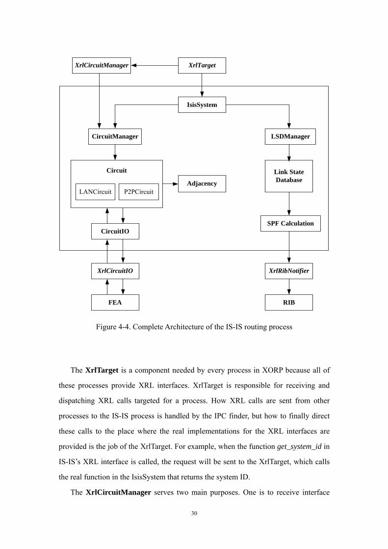
Figure 4-4. Complete Architecture of the IS-IS routing process
The XrlTarget is a component needed by every process in XORP because all of
these processes provide XRL interfaces. XrlTarget is responsible for receiving and
dispatching XRL calls targeted for a process. How XRL calls are sent from other
processes to the IS-IS process is handled by the IPC finder, but how to finally direct
these calls to the place where the real implementations for the XRL interfaces are
provided is the job of the XrlTarget. For example, when the function get_system_id in
IS-IS’s XRL interface is called, the request will be sent to the XrlTarget, which calls
the real function in the IsisSystem that returns the system ID.
The XrlCircuitManager serves two main purposes. One is to receive interface

31
configuration requests directed from the XrlTarget and execute the configurations on
the corresponding circuit object; the other is to obtain interface state information from
the XORP platform, more specifically from the FEA.
The XrlCircuitIO has the same role as the CircuitIO object mentioned earlier. It
sends IS-IS packets to and receive the packets from the FEA.
The XrlRibNotifier registers with RIB and sends to RIB the route updates it
receives from the SPF computation process.
4.2.3 Discussion of the System Architecture Design Issues
The architecture design just described has some merits because of which we
chose to use it, but it also has some short-comings as any other system design which
we gradually found out in the development process. These issues are discussed and
analysed in this section.
Advantages
1. The design properly reflects the relationship between the subnetwork
dependent functions and subnetwork independent functions described in the
RFC. As mentioned before, the Circuit module masks the subnetwork
dependent functions from the higher levels by putting them into two
subclasses corresponding to two different types of subnetworks.
2. Dividing the system into two subsystems has some advantages for the project.
A most important one is that it enables us to accordingly divide the group into
two subgroups, each working on one subsystem. Additionally, since the data
only flows between two subsystems at the top level, their respective
implementations are well hidden from each other. Therefore, when our two
subgroups are working on their own part, they do not have to know too much
about the internal structure of the other part, and as long as the interfaces
between them stay the same, they will not be affected by the changes in the
other subsystem.
3. Although we have been referring to the two subsystems that the system is

32
divided into as “subnetwork dependent subsystem” and “subnetwork
independent subsystem”, it is not exactly accurate in that the first subsystem
in fact involves some functions defined as “subnetwork independent”. The
subnetwork independent functions introduced earlier include both the update
process and the decision process, but in our system, the update process is
handled jointly by the two subsystems.
The update process is responsible for the generation and propagation of
LSPs. And in our system, the LSP generation is handled by the
CircuitManager component, while the LSP propagation is controlled by the
LSDManager. Alternatives would have been to put the whole update process
in CircuitManager and Circuit, or in LSDManager and LSD. The reasons why
we did not choose them are explained below.
In order to generate a system’s own LSP, we need to check what
adjacencies each circuit on the system has, and to add the information of
those adjacencies with the right attributes and status into the LSP. Since the
CircuitManager contains all the circuits and therefore their adjacencies, it is
natural for it to handle the generation itself. Similarly, in order to control the
propagation of LSPs, we need to query the LSDs for the flags set for each
circuit that represent on which circuits an LSP needs to be sent out, which is
also relatively easy for the LSD to finish internally. On the contrary, if the
update process is placed entirely on either side, either the LSDManager would
have to use interfaces provided by the CircuitManager to query circuits about
their adjacencies, or the CircuitManager would have to use interfaces
provided by the LSDManager to query the flags stored in the LSD. As a result,
one side would need to know about and might be affected by the other side’s
internal organisation, which weakens their independency from each other. An
additional advantage of our design is that two subsystems involve a
comparable amount of work and therefore easier for us to assign resources.
Disadvantages
One major problem with the design we have found so far is actually a

33
side effect of the split up of the update process. Since there are a number of
subsidiary functions in the update process, and for some of them the choice
of where to put them is not obvious, it had not been made very clear which
should be put where from the beginning. As a result, there is a danger that
some functions would be missed out and the two groups have to continually
check with each other.
4.4 Design and Implementation of Major components
This presents the design and implementation of the major components in the
IS-IS system. The first one to be introduced is the PDU encoder/decoder for it is the
most basic module, and then the major components in the Subnetwork Dependent
Subsystem and Subnetwork Independent Subsystem are described respectively. We
both include enough details for understanding the implementation, and also highlight
the relevant design decisions we have made and the reasons behind them.
4.4.1 PDU Encoding and Decoding
PDU encoding and decoding is a fundamental and most basic component in the
protocol implementation. This section gives a brief description of this module.
1. IS-IS Packet types and Packet Format
There are four general types of packets used in IS-IS:
·Intermediate System-to-Intermediate System Hello (IIH)
IIH packets are used by routers to detect neighbors and form adjacencies.
There are two different subtypes of IIH for LAN and Point-to-Point networks.
In addition, IS-IS uses ISH to initialise adjacency on Point-to-Point links,
which is similar to IIH but is an End System-to-Intermediate System (ES-IS)
PDU.
·Link-State Packet (LSP)
There are four types of LSPs: Level 1 pseudonode, Level 1
nonpseudonode, Level 2 pseudonode, and Level 2 nonpseudonode.
34
• Complete sequence number PDU (CSNP)
CSNPs contain a list of all LSPs from the current database. CSNPs are used to
inform other routers of LSPs that may be outdated or missing from their own
database. This ensures that all routers have the same information and are
synchronised.
• Partial sequence number PDU (PSNP)
PSNPs are used to request an LSP (or LSPs) and acknowledge receipt of
an LSP (or LSPs).
LAN IIH, LSP, CSNP and PSNP packets all can be either level 1 or level 2.
The header part of IS-IS packets consists of two parts: the first 8 octets contain
the same fields for all types of packets while the rest varies. Following the packet
header is a set of variable length fields, which are encoded in the form of “Code,
Length, Value (CLV)” triplets. Codes are defined for different types of information
that is allowed to add into the packets.
2. Class Organisation
Since all IS-IS packets have a common header part and some common operations,
for example, the CLV fields need finally be added to the packet as binary data
regardless of the type of information, it is desirable to have a base class IsisPDU for
this purpose. Subclasses LANHelloPDU, P2PHelloPDU, Lsp, CSNP and PSNP
handle the packet-specific operations themselves.
3. Key Issues in implementation
The implementation of this module involves a lot of low-level programming,
which did result in some problems especially at the beginning.
-- Struct vs. Class
Because of the influence of C-style programming, a number of structs were
initially designed to represent both the header part and the variable length fields.
While it is reasonable to use structs to represent headers for they are not visible to
outside classes, it is really not a good idea for the CLVs for they need to be passed in
from other classes. If we use structs for them, that means other classes had better use

35
the same structs as well, which would fill the system with structs both harder to
manipulate than classes and undermine the object-orentation of the whole program.
-- Byte Order and Word Alignment
These are two commonly encountered problems in network programming, and
therefore require careful treatments. As just mentioned, the packet headers are
represented using structs, and because of word alignment, the actual size of a struct
may be larger than the header it represents, thus resulting in gap between successive
fields in the header. This is avoided by using arrays of uint8_t (unsigned char) instead
of uint16_t (unsigned short) or uint32_t (unsigned long) data types. As for byte
ordering, it is important to keep in mind that the conversion between host order and
network order is a two-way operation and therefore should appear in pairs upon
packet transmission and reception, otherwise some data would be messed up.
-- Use of existing and common classes
As mentioned before, the libxorp library provides a number of classes to contain
information about IPv4 addresses, MAC addresses and etc. A biggest advantage of
this approach is that other classes can deal with them at a higher level, without
worrying about how the data is manipulated internally. For example, if we store an
IPv4 address only as an in_addr type, a lot of repetitious memory copy operations
associated with it would be needed, while now this issue is left for the class itself
which can be easily reused, and can be debugged and tested more easily. Inspired by
this approach, we also defined a number of classes for some frequently used data,
such as SystemID, AreaAddress, LanID, which are essentially octet arrays.
4.4.2 Modifications to the FEA
Before moving to introducing the subnetwork dependent subsystem, it is
necessary to explain some modifications we have done to the FEA for IS-IS packet
transmission and reception.
As mentioned in chapter 3, we have decided to choose the FEA as the place to

36
handle packet transmission/reception for IS-IS, and therefore some additional
interfaces specially for IS-IS packets are needed in both the FEA and the IS-IS. We
created two new XRL interfaces: one for packet transmission and registering interests
(fea_isis_pkt) and the other for packet reception (fea_isis_pkt_client).
The fea_isis_pkt interface is implemented by the FEA and includes functions to
be called by the IS-IS:
·To send IS-IS packets to a destination MAC address on a certain interface
·To register/unregister for receiving IS-IS packets on a certain interface
The fea_isis_pkt_client is implemented by the IS-IS and has a single function to
be called by the FEA when a IS-IS packet is received by the router.
These interfaces conceptually indicate the way we designed to handle IS-IS
packet transmission and reception. However, we did not attempt to provide the actual
implementation in the FEA which handles sending packets to and receiving them from
the real network because it is out of the scope of our project.
4.4.3 Circuit & CircuitIO
The Circuit module plays an important role in the system in that it is the bridge
connecting the higher level components and the underlying network, and provides a
uniform interface to the subnetwork independent functions.
This component mainly performs the following functions:
·Transmit and receive packets form the underlying network
·Exchange Hello packets and maintain adjacencies with neighbours
·Participate in LAN DIS election on broadcast networks
These functions are fundamental because the operations for generating local link
state information, propagating link state information as well as calculating the SPF
and hence the final route table all rely on them. And packet transmission and
reception should clearly be the first step.
1. Packet Transmission and Reception
Although the actual IS-IS packet transmission and reception is handled by the

37
FEA, for the IS-IS system itself, Circuit is the place where all packets go out and
come in. The mechanism for passing packets between the Circuit and the FEA is
described as follows.
First, there are four relevant classes: Circuit, CircuitIOUser, CircuitIO and
XrlCircuitIO. CircuitIO and CircuitIOUser are the base class for XrlCircuitIO and
Circuit respectively. CircuitIO represents an I/O object associated with an interface,
while CircuitIOUser represents an object which needs to use the I/O object to send
and receive packets on that interface. Therefore, each CircuitIOUser object is
associated with a CircuitIO object, and this one-to-one binding happens when these
objects are created. More specifically, the CircuitIO class takes the reference to a
CircuitIOUser object as a parameter of its constructor, which means a CircuitIO
object cannot be created without a CircuitIOUser object to be associated with it. And
the CircuitIOUser class holds the pointer to a CircuitIO object, known as its
io_handler, which can be accessed by its subclasses. In this way, each circuit has an
I/O object dedicated to it, which makes the packet I/O more efficiently and reliably.
As shown in figure 4-5, the communications between Circuit and XrlCircuitIO
actually happen via their base classes. For example, the functions for sending packets
are defined in CircuitIO as pure virtual functions, which are actually implemented by
XrlCircuitIO. Thus when Circuit calls these functions, it is actually calling those real
functions in XrlCircuitIO. But the Circuit knows about that, which is nice because we
do not want the internal components of the IS-IS to need to know about the XORP
integration components. Additionally, in order to guarantee successful packet
transmission, the Circuit will be notified by the FEA via the callback mechanism
when the transmission is completed.
As for reception, the incoming packets are first delivered to the
XrlCircuitManager, which should decide which Circuit object a particular packet is
destined to according to the interface on which it comes in, by searching the list of
circuits it monitors and manages. When a Circuit object actually receives a packet, it
checks the field in the packet header indicating the packet type and constructs
different types of PDU objects accordingly and dispatches them to the proper

38
functions.
Figure 4-5. The mechanism for packet I/O
2. IIH Exchange and Adjacency
Next responsibility of the Circuit module is to discover the neighbours of the
system, to establish adjacencies with them accordingly and to maintain the
adjacencies thereafter. The relevant operations are mostly different for broadcast and
point-to-point subnetworks, and therefore implemented in Circuit’s two subclasses
LANCircuit and P2PCircuit respectively.
For LANCircuit, once the Circuit is configured and enabled, it starts to multicast
Hello packets to the multi-destination address AllL1ISs or AllL2ISs according to the
level of the circuit. IIHs are sent periodically according to a configurable value
hello_interval, or when the metric or priority of the circuit changes, to notify the
neighbours with the latest state of the circuit. Therefore, an iih_timer need to be set to
trigger the transmission whenever it expires.
Adjacencies are formed based on the Hello packets the circuit receives from other

39
routers, and are separate for Level 1 and Level 2 neighbours. Therefore, each circuit
holds two separate lists of Adjacencies for Level 1 and Level 2 respectively.
On reception of Hello packets from neighbours, the system needs to perform some
acceptance tests before forming an adjacency, for example, a Level 1 neighbour must
have at least one common area address with our system to become adjacent. When an
Adjacency is formed, it is in the state INITIALISING, and only when our system
receives a second Hello packet from the same adjacency which has our own MAC
address in the LAN Neighbours field, which means the other side has also accepted us
as its adjacency, can it set the adjacency state to UP. Figure 4-6 shows this process. A
holding timer needs to be set for each adjacency, which will be purged from the
adjacency database if it is not refreshed before the timer expires.
Figure 4-6. Adjacency State Machine in LANCircuit
For P2PCirucit, the major difference compared to LANCircuit is that an interface
on a point-to-point link only has a single neighbour, while an interface on a LAN
usually has multiple neighbours. From an implementation point of view, a router
initializes an adjacency by sending an ISH packet to its neighbour, and the checks
before forming adjacency are simpler than those in LANCircuit.
The main issue in implementing these functions is that because a lot of conditions
need to be checked when receiving a Hello packet, forming and updating an adjacency,

40
many multinested for and if loops are used. Therefore, we need to be very careful to
get them right, and even so, the correctness of this code can only be verified when this
component is actually tested.
Adjacency database is maintained by all systems to keep track of neighbours.
There are two approaches to build the database. The first one uses c++ template <list>
to implement. The second one uses c++ template <map> as the basic data structure
which is proved more simple and efficient than the first approach. We use <map> to
store all the adjacencies associated with a particular circuit. Map is a sorted associate
container that associates objects of type key with objects of type data which means
that its value type is pair<const Key, Data>. It is also a unique associative container,
meaning that no two elements have the same key. Map has the important property that
inserting a new element into a map does not invalidate iterators that point to existing
elements. Erasing an element from a map also does not invalidate any iterators, except,
of course, for iterators that actually point to the element that is being erased. The
availability of this structure led us to demonstrate it by a simple solution to a
well-known problem. Moreover, its performance is substantially better as well. The
database has the basic function required in this system including search, add and
delete a particular circuit, update the database and print the information etc.
3. LAN Designated IS
This operation only exists in LANCircuit. In order to perform the DIS election,
each interface on the LAN is assigned with a priority between 0 and 127, which is a
configurable parameter. The priority is advertised in the Hello packets sent out by the
interface. The router with the highest priority circuit becomes the DIS on the LAN,
with numerically higher MAC address breaking ties.
It was originally considered to develop a separate class to represent the DIS,
however, it was later realised that it would be redundant and unwanted because the
DIS is definitely either ourselves or one of our adjacent routers and therefore the
relevant information for a DIS will be able to be stored in either the Adjacency or
Circuit class. And in order to perform the MAC address comparison, new operators
were added to the MAC class in libxorp code.

41
4.4.4 CircuitManager & XrlCircuitManager
These two components are closely related and they are both responsible for
managing a collection of circuits on which the IS-IS routing process runs. They both
maintain a list of these circuits which must be up-to-date and identical. The reason of
having two components is to separate the part which needs to interact with the XORP
platform.
Key Issues in Implementation
-- Obtaining interface state information from the FEA
The FEA is responsible for maintaining interface configuration state, and it
updates the configuration state based on information from forwarding hardware and
configuration requests from the router manager. In addition, it can mirror its interface
configuration state across routing processes, the RIB, and any other interested parties.
The interface configuration information is held within an IfMgrIfTree class, which
contains all the information associated with physical interfaces, virtual interfaces, and
addresses associated with virtual interfaces. Within the IfMgrIfTree class, physical
interfaces are represented by IfMgrIfAtom instances, virtual interfaces by
IfMgrVifAtom instances, and addresses by instances of IfMgrIPv4Atom and
IfMgrIPv6Atom.
An instance of the IfMgrIfTree is maintained by the FEA and by remote processes
which are interested in the interface configuration state. Remote processes need to
have an IfMgrXrlMirror instance, which contains the IfMgrIfTree instance and as its
name suggests, is responsible of mirroring the interface state from the FEA. When
changes on interface state occur, updates are first dispatched to the local IfMgrIfTree
instance and if successful forwarded to each remote IfMgrXrlMirror instance. In this
way, the information about interface state held by routing processes such as IS-IS can
be conveniently synchronised with that maintained by the FEA.

42
4.4.5 Link State Database
The LSD module contains two main parts: one is the actual Link State Database
of the system which stores latest local and received link state information; the other is
the operations that manage the LSP propagation, mainly the manipulation of SRM and
SSN flags. This section gives an explanation on the design and implementation of
both parts.
1. Database operations
The link state database (LSD) is the most important database in an IS-IS system.
Its input comes from two sources: after a system generates its new LSP(s) reflecting
the current connection state with its neighbours periodically or driven by some events,
they are stored in the LSD; and when an LSP is received from another router, it is
directly forwarded to the LSD. Upon the reception of an LSP, the LSD checks
whether an LSP from the same source already exist in the database, and if it does,
whether it is newer, older than or equals to the existing one, after which the LSD can
determine to add the new LSP, or to replace the old one or just drop it.
The LSD keeps the link state information up to date by making use of the
remaining lifetime attribute associated with an LSP. Each LSP has a remaining
lifetime of 1200 seconds (known as MaxAge) when generated, and its originator
periodically refreshes the LSP to prevent the time from reaching zero. If an LSP’s
remaining lifetime reaches zero thus expires, it will be kept for another 60 seconds
(known as ZeroAgeLifetime) before it is purged from database.
The LSD also carries out a purge of an LSP if it is received with an incorrect
checksum, by setting its remaining lifetime to zero, removing the payload, keeping
the header, and re-flooding it. The originator of this LSP has to generate a new LSP
after receiving this purged packet.
As mentioned before, an IS-IS system may have two link state databases if it is an
L1/L2 router, for which reason an LSDManager is needed to manage them both. The
LSDManager is responsible for forwarding LSPs of different levels to the appropriate
LSD. Moreover, it provides interfaces for other modules to access and to

43
communicate with the link state databases.
Finally, the Link State Database is the direct input for the SPF computation
module, which means it should be able to collect and forward the connection and
metric information residing in each LSP to the SPF module to perform the calculation.
In summary, the LSD should at least include the following functions:
● Add an LSP to the database / Remove an LSP from the database / Retrieve an
LSP from the database
● Compare two LSPs to decide one is newer, older than or equals to the other
● Automatically purge an LSP from the database when it expires
● Collect the necessary information from stored LSPs and pass it to the SPF
computation module
2. SRM & SSN Flags Operations
The SRM (Sending Routing Message) and SSN (Sending Sequence Number)
Flags are used to guarantee the reliable propagation of LSPs. Each LSP is associated
with an array of SRM flags, and each element in the array corresponds to a circuit on
the system over which routing messages are to be exchanged. The LSP should only be
transmitted on the circuits whose SRM flags are set. The SSN flags are used in the
same manner to indicate which LSP(s) should be included in the next PSNP (Partial
Sequence Number PDU) transmitted on each circuit. Therefore, whenever a new LSP
is generated or received from other systems, the SRM/SSN flags need to be set or
cleared as appropriate.
Although the RFC does not explicitly say where these flags operations should be
performed, since the flags do not exist in the actual Link State packets exchanged
between routers, it is reasonable to create some data structure in the LSD to hold these
flags associated with each LSP stored in it. Besides, in some cases, an LSP needs to
have its SSN flag set even though it is not yet stored in the database. For example,
when receiving a CSNP (Complete Sequence Number PDU), a system may find some
LSP entries listed in the packet which it does not have, then it will need to set the SSN
flags for these “nonexistent” LSPs. For these reasons, the SRM/SSN flags operations
are placed in the LSD module, and new data structures are created dedicatedly for the

44
SRM/SSN flags. Another benefit of this design is that, if the flags are placed within
each LSP record in the database, we would need to search the whole database every
time to find out the LSPs waiting to be transmitted, but with additional data structures
for flags only, we can just put the indexes of the associated LSPs in these structures.
In this way, the efficiency is improved because we only need to search a subset of the
link state database.
The following functions are also needed in the LSD module to facilitate the
manipulation of SRM/SSN flags:
● Data structures to store SRM/SSN flags
● Set and Clear SRM/SSN flags
● Search for the LSPs waiting to be transmitted or acknowledged
● Update the SRM/SSN flags when Circuit up/down events happen
Key Issues in Implementation
-- Database
(1) The Map class provided by the C++ Standard Template Library is the ideal
container to hold the potentially large number of LSPs in the database, especially with
its feature of automatically sorting the data entries by index.
(2) An LSPRecord class is developed to wrap the LSP packets stored in the LSD.
The reason for this choice is that some extra information other than that contained in
an actual LSP is necessary for managing the link state information in the database. For
example, it would be difficult and inconvenient for the database to continuously
observe and update the remaining lifetime of an LSP. Instead, we convert the value of
the remaining lifetime field in an LSP to an expiration time attribute indicating the
absolute time when this LSP expires and store this attribute in the LSPRecord class.
(3) In order to purge expired LSPs from the database, some timer(s) need be
created. A naive solution would be to set a separate timer for each individual LSP,
which would definitely be an undesirable overhead especially for large networks.
Thus a better choice is to have a single timer (known as the purge timer) for the LSP
whose expiration time is nearest to the current time. A callback will be invoked to
purge this LSP when the timer expires, and the purge timer will then be rescheduled

45
for the next LSP whose expiration time is now the nearest. This design requires the
LSPs in database sorted by their expiration time, which can be conveniently achieved
by creating a Multimap, with the expiration time variable as its index.
(4) After the purge timer expires, a new timer is created to count down
ZeroAgeLifetime before each expired LSP is removed. A timer list is created to hold
these temporary timers and ensure that they are removed from the list as soon as they
expire. Although we should try to avoid the situation of having a separate timer for
each individual LSP, since the number of LSPs which are waiting to be removed at
any particular moment is usually small, the overhead caused by these temporary
timers can be ignored.
(5) All these timers are created inside the LSD class: the purge timer is initialized
when the LSD is created and rescheduled when an LSP is added or removed; the
temporary timers are created by the purging operation and automatically destroyed
when they expire. Therefore, the users of the LSD module do not need to know
anything about these internal operations which are handled automatically as soon as
an LSD object is instantiated.
-- SRM/SSN Flags operations
(1) While the LSPRecord class first seems to be the proper place to hold the flags
information, there are some cases where the LSPs that need to have SSN flags set are
not in the database at all, which means no LSPRecord objects would have been
created for these LSPs. And in order to improve the efficiency of searching for LSPs
waiting to be transmitted, a Map is created to hold the indexes of LSPs with the SRM
flag set, and another for those with the SSN flags set.
The SRMFlags and SSNFlags class are created to hold the LSPs which have
SRM or SSN flags set on a particular Circuit, which means each of them need to have
an internal database structure as well. For example, to find out which LSPs are
waiting to be sent on Circuit C, firstly, we can find the corresponding SRMFlags
object associated with Ciricuit C from srm_map, then search the internal map of
SRMFlags object we found to find out the LSPs’ indexes we want. We can see this
clearly from the diagram below.

46
All the flags operations of SRM/SSN flags are wrapped in four methods, they are,
void set_SRMflag( OP op, LSPRef lsp, Circuit::CircuitRef c);
void clear_SRMflag( OP op, LSPRef lsp,Circuit::CircuitRef c);
void set_SSNflag( OP op,LSPRef lsp,Circuit::CircuitRef c);
void clear_SSNflag( OP op, LSPRef lsp, Circuit::CircuitRef c);
where lsp is the reference to the LSP whose flags are to be modified, c is the reference
to the Circuit on which this LSP is going to be modified, the OP is a enum variable I
defined as,
typedef enum {ALL, ALL_BUT, ONLY} OP;
With these convenient methods, other operations can set or clear the SRM/SSN
flags without knowing anything about the structure used to hold the flags. For
example, if we want to set SRM flag for lsp0 on all the Circuits other than circuit c,
just call,
Set_SRMflag(ALL_BUT, lsp0, c).
All these flags operations are based on the presumption that, the database always
knows the most updated information about the Circuits status. The circuit up or circuit
down events happen during the operation of a system must be notified to database,
otherwise, it has no way to figure out what circuits are currently valid and could not
set the SRM/SSN flags properly. Hence two methods are provided in LSD, to be
called by CircuitManager are when such events happen,
void circuit_up(Circuit::CircuitRef c)
void circuit_down(Circuit::CircuitRef c).
Periodically, the update process needs to scan the database for the LSPs with
SRM flag set, and send them out on appropriate circuit when they are found. To hide
the details of the SRM/SSN flags search from the users of database, the operations to
found out these LSPs and send them out on circuits are included in one single method,
which will be called by update process upon the expiration of minimum transmission
intervals.

47
4.4.6 Shortest-Path-First (SPF) Calculation
The SPF (Shortest Path First) algorithm, also known as Dijkstra algorithm, is
used by IS-IS protocols to obtain the best paths through the network. The code
performing the Dijkstra computation does exist in one of the XORP library packages
(libproto), however, some modifications must be made before we can use it in our
scenario.
Firstly, the SPF in libproto is only defined for IPv4, IPv6, and string. But in our
IP-only IS-IS protocol scenario, each node in SPF network could be either an IP
network or an Intermediate System, identified by five octet value. This requires me to
provide a new class to denote the nodes in SPF network, which can present either an
IP network or a Intermediate System, and at same time, keep transparent to SPF
computation.
Secondly, the output of the original code consist only the operation name, the
destination, and the next hop, without metric, but to forward these routes information
to RIB, a metric for each path is necessary. Therefore, modification of the algorithm
and output format is needed.
Finally, if a node in SPF network is pseudo node, then this node can not be the
next hop node for any destination, because this node does not exist actually. Hence
some mechanism, such as a flag, is necessary to help distinguish pseudo nodes from
real nodes.
Key Issues in Implementation
In order to use the SPF computation code from libproto, a new class must be
created to present either an Intermediate System or an IP network. The new class is
named as IsisNode, which is defined as,
Each time the computation is performed, a list of RouteCmd is returned as the
result of the computation. Only what has changed from previous time the computation
was run can be fetched from this command list. The original RouteCmd consists of a
command (ADD, REPLACE, and DELETE), a destination node, and the next hop
node to reach that node. To make it suitable for our situation, a metric attribute is
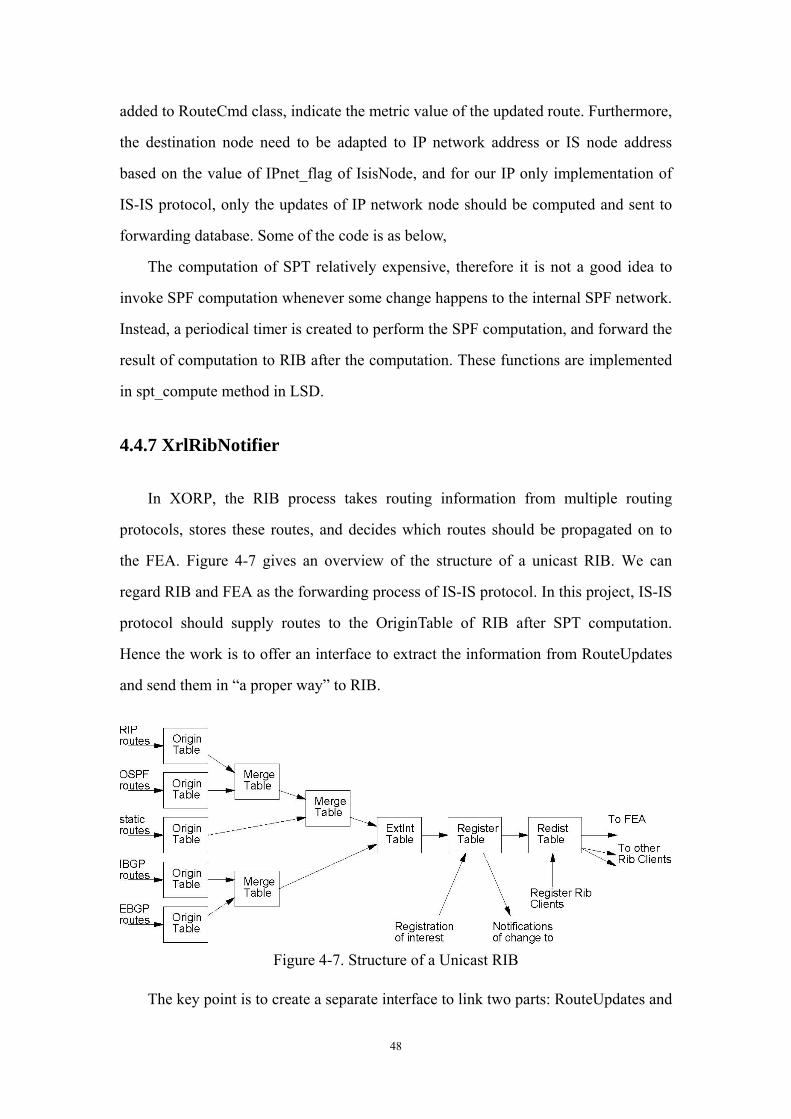
48
added to RouteCmd class, indicate the metric value of the updated route. Furthermore,
the destination node need to be adapted to IP network address or IS node address
based on the value of IPnet_flag of IsisNode, and for our IP only implementation of
IS-IS protocol, only the updates of IP network node should be computed and sent to
forwarding database. Some of the code is as below,
The computation of SPT relatively expensive, therefore it is not a good idea to
invoke SPF computation whenever some change happens to the internal SPF network.
Instead, a periodical timer is created to perform the SPF computation, and forward the
result of computation to RIB after the computation. These functions are implemented
in spt_compute method in LSD.
4.4.7 XrlRibNotifier
In XORP, the RIB process takes routing information from multiple routing
protocols, stores these routes, and decides which routes should be propagated on to
the FEA. Figure 4-7 gives an overview of the structure of a unicast RIB. We can
regard RIB and FEA as the forwarding process of IS-IS protocol. In this project, IS-IS
protocol should supply routes to the OriginTable of RIB after SPT computation.
Hence the work is to offer an interface to extract the information from RouteUpdates
and send them in “a proper way” to RIB.
Figure 4-7. Structure of a Unicast RIB
The key point is to create a separate interface to link two parts: RouteUpdates and

49
OriginTable of RIB, and the interface should provide the functions including:
Extraction from RouteUpdates to proper parameters
Insertion of IGP table
Deletion of IGP table
Insertion of Routes (IPv4 or IPv6)
Replacement of Routes (IPv4 or IPv6)
Deletion of Routes (IPv4 or IPv6)
Lookup of NextHop By Destination
The required parameters sent to RIB are:
Network address prefix of the route
Nexthop ( the address of the next-hop router toward the destination )
Routing metric The structure of the interface is demonstrated in figure 4-8:
RouteUpdates RibNotifier RibRegister RIBSend_add_route()Send_to_rib() Send_add_route4()
Figure 4-8. Structure of XrlNotifier Module
The first point to mention is that, although this project intends to support IPv4
only, interfaces for IPv6 should be considered when it is possible considering further
extension. Based on this thinking, RibRegister is implemented as a template class.
The second point is that RibRegister needs to co-ordinate with the RIB which is
within a different process and may be on a different machine. In XORP, different
process communication should base on Service Class. A service instance is an entity
that can be logically started and stopped. Therefore service should be introduced to
implement RibRegister. As a service, RibRegister should at least includes startup()
method and shutdown() method. Before startup(), an instances state is
SERVICE_READY. When startup() is called in the main eventloop of ISIS process, it
should register a routing table called “IS-IS” and transition into
SERVICE_RUNNING. When in SERVICE_RUNNING state updates are sent to the
RIB. When shutdown() is called it remove the “IS-IS” routing table from the RIB. At

50
any time it may fall into state SERVICE_FAILED if communication with the RIB
fails.
Finally, callback is widely used in RibRegister to receive the returns from RIB
process. For example, when RibRegister passed routes information to RIB, an
XrlError is returned to Callback function. If it is not XrlError::OKAY(), we know the
operation is failed. However if there is no limit to the numbers of callbacks in-flight it
would cause other tasks awaiting dispatch by the eventloop. Therefore the maximum
number of Xrls inflight should be set when RibRegister instanced. When RibRegister
try to “talk to” RIB, numbers of Xrls inflight should be increased, such as startup(),
add_route() etc. While numbers of Xrls inflight should be decreased when callback
function received the return or service is shutdown.
RibNotifier can be regarded as “the conjunction” of RibRegister and
RouteUpdates. For the part of RibRegister, it is no doubt that RibNotifier calls it to
perform the function of communication with RIB. For the part of SPT, at first, a list is
constructed to hold these routes information after SPT class sent them. XorpTimer is
used to process the list periodically and send the parameters to RibRegister. Although
this way saves excessive effort to process, it is not a good trade-off to swift response
because the process procedure is not expensive compared with SPT computation. So
it was abandoned and we process the routes received immediately. That means when
SPT class called the method send_to_rib in RibNotifier, the routes information will be
extracted and send to RibRegister.
51
Chapter 5: Testing and Evaluation
5.1 Set up testing environment
The testing for those components which interact with other processes in the
XORP platform needs to be carried out in an environment where these processes are
running as well as properly configured. This environment will also be necessary for
the integration test. Therefore, some preparation work needs to be done in advance so
that later testing would not be held back by this problem.
1. Start the Finder/FEA/RIB daemons
As we introduced earlier, the router manager is responsible for starting the
processes on a XORP router in one go according to a configuration file. However, it is
usually not desirable to do so in testing for a couple of reasons: we may need to
monitor the debugging messages generated by each individual process, which are not
available via the router manager; also, we need to run the dummy_fea instead of the
real FEA for testing purpose, which the router manager does not do either.
Three processes need to be running for testing IS-IS: xorp_finder, xorp_fea (or
xorp_fea_dummy) and xorp_rib. The finder needs to be started first because all other
processes must register with the finder once they are started. The finder listens to a
certain port after started, which is by default 19999 on the localhost. Although these
programs are supposed to take command line arguments which specify the port
number of the finder, some processes, such as xorp_rib, do not support this yet.
Therefore, if the default finder port is being used by another process on the host, the
RIB would not able to be started. In order to solve this problem, our supervisor
discussed with other XORP developers and changed the way the finder port is
configured. It is now specified by setting the value of an environment variable
XORP_FINDER_SERVER_PORT, and then all XORP processes will have the same
information about where to connect to the finder.
Shell scripts were written to save the time and effort of typing the commands to
52
run these daemons every time.
2. Configure the FEA
The FEA has to be configured with necessary information such as interface state
before IS-IS itself can be actually configured because IS-IS would need to consult
the FEA about the information of interfaces. The FEA provides a number of functions
in its Interface management XRL interfaces which we can call to obtain information
or carry out configurations, such as create_interface, delet_interface, create_vif,
delete_vif, configure_interface_from_system, and get_configured_interface_names,
etc. If we are running the real FEA, we can call configure_interface_from_system to
request it to learn the interface information from the underlying system; and if we are
running the dummy FEA, since it knows nothing about the real interfaces or networks
whatsoever, we need to explicitly create interfaces and associated virtual interfaces as
well as to set the various parameters where necessary.
This is where we can use the program “call_xrl” provided in the libxipc library.
The program takes a complete XRL call as its argument. An example is shown below:
Command:
bash-2.05b$./call_xrl "finder://fea/ifmgr/0.1/get_system_interface_names"
Response:
ifnames:list=:txt=dc0,:txt=faith0,:txt=lo0,:txt=ppp0,:txt=sl0,:txt=vr0
The command requests the FEA to return the information about what physical
interfaces the system has, and gets a response of a list of interface names.
A point to note is that some configuration function calls must be carried out as a
transaction, and some related methods are provided: start_transaction,
commit_transaction and abort_transaction. The start_transaction function returns an
integer known as “Transaction ID”, which must be used as an argument in every XRL
call that needs to be called within a transaction. Shell scripts are also necessary here
for performing these configurations as transactions, for the Transaction ID expires
extremely shortly after calling start_transaction, making it impossible to finish a
transaction by typing commands in command line. The shell scripts written for this
purpose make use of an existing script xrl_shell_funcs.sh provided by the FEA.

53
5.2 Unit Testing and Integration Testing
Unit testing plays an important role in any software development process.
Particularly, since the IS-IS system is large and complex and we are not likely to
begin system integration early, it is very important for us to carry out proper unit tests
for individual components along with the development to make sure they can perform
their functions as expected. This section briefly describes some example tests to show
the main aspects we have tested for the major components.
5.2.1 Packet Encoder and Decoder
1. Tested Functions
Tests are performed for this module mainly to verify the following functions:
A PDU object can be correctly constructed with given information, and the
attributes of a PDU can be correctly accessed
The information can be correctly encoded and placed in the right position of
the packet header or variable length part as defined by the “Structure and
Encoding of PDU” section in RFC 1142 and RFC 1195
These functions are used by the system when sending packets.
A PDU object can be correctly constructed with binary data
The binary data can be correctly decoded from and converted to the
corresponding attributes of a PDU object.
These functions are used by the system when receiving packets.
2. Testing Approach:
The tests for this component use the d_help library, which was provided by our
course director Dr. Saleem Bhatti in the Z23 course module. It provides functions to
print out data stored in certain memory space in a similar format as tcpdump. All six
PDU classes (LANHelloPDU, P2PHelloPDU, Lsp, CSNP, PSNP, and ISH) are tested
respectively to validate the symmetric and correct behaviours of the encoder/decoder.

54
5.2.2 Circuit
Tests are performed in this module to verify the subnetwork independent
functions described before. A Circuit object is normally created when an interface on
the router is configured for IS-IS, but at the unit testing stage the Circuit module has
not integrated into the XORP platform yet, Circuit objects are therefore explicitly
created and set with necessary parameters in these tests. One example test scenario
and results is shown below. In this test, there are three Circuits: lan_circuit_1,
lan_circuit_2 and lan_circuit_3. They form adjacencies with each other by exchanging
IIHs, and then the LAN DIS is elected.
Step 1: Create and configure three Circuit objects: ---------------lan_circuit_1---------------- lan_circuit_1: set up... SYSTEM ID is : 0200 6465 6667 ----------------lan_circuit_2---------------- lan_circuit_2: set up... SYSTEM ID is : 0200 6465 6668 ----------------lan_circuit_3---------------- lan_circuit_3: set up... SYSTEM ID is : 0200 6465 6669 ----------------end of set up object--------- Step 2: lan_circuit_1 receives an IIH from <<lan_circuit_2>> [ 53294 +718 isis_circuit.cc circuit_io_receive ] LAN_L1_HelloPacket received... SYSTEM ID: 0200 6465 6668 [ 53294 +1262 isis_circuit.cc event_receive_iih ] pkt :: size of lan_neighbours is : 0 [ 54071 +1733 isis_circuit.cc print_adj_list_content ] Adjacency_list size is : 1 neighbor_id is : 0200 6465 6668 neighbor_hold time is : 40 adjacency _status is : 0 neighbor_priority is : 2
Lan_circuit_1 receives packet from lan_circuit_2 accept it as an adjacency with
the adjacency state of 0 (INITIALISING).
Step 3: lan_circuit_1 receives packet from <<lan_circuit_3>> [ 53294 +718 isis_circuit.cc circuit_io_receive ] LAN_L1_HelloPacket received... SYSTEM ID: 0200 6465 6669
55
[ 53294 +1262 isis_circuit.cc event_receive_iih ] pkt :: size of lan_neighbours is : 0 [ 54071 +1733 isis_circuit.cc print_adj_list_content ] Adjacency_list size is : 2 neighbor_id is: 0200 6465 6668 neighbor_hold time is : 40 adjacency_status is : 0 neighbor_priority is : 2 neighbor_id is: 0200 6465 6669 neighbor_hold time is : 40 adjacency _status is : 0 neighbor_priority is : 3
When lan_circuit_1 receives packet from lan_circuit_3 and accept it as an
adjacency as well with the state INITIALISING. lan_circuit_1 now has two
adjacencies.
Step 4: lan_circuit_2 receives packet from <<lan_circuit_1>> [ 53294 +718 isis_circuit.cc circuit_io_receive ] LAN_L1_HelloPacket received... [ 53294 +1262 isis_circuit.cc event_receive_iih ] pkt :: size of lan_neighbours is : 2 [ 54071 +1733 isis_circuit.cc print_adj_list_content ] Adjacency_list size is : 1 neighbor_id is: 0200 6465 6667 neighbor_hold time is : 40 adjacency_status is : 1 neighbor_priority is : 1
lan_circuit_2 receives the Hello packet from lan_circuit_1, in which two
neighbours are advertised, including lan_circuit_2 itself. Therefore, the adjacency
state is changed to 1 (UP).
Step 5: lan_circuit_1 receives packet from <<lan_circuit_2>> [ 53294 +718 isis_circuit.cc circuit_io_receive ] LAN_L1_HelloPacket received... SYSTEM ID: 0200 6465 6668 [ 53294 +1262 isis_circuit.cc event_receive_iih ] pkt :: size of lan_neighbours is : 1 [ 54071 +1733 isis_circuit.cc print_adj_list_content ] Adjacency_list size is : 2 neighbor_id is: 0200 6465 6668 neighbor_hold time is : 40 adjacency _status is : 1 neighbor_priority is : 2 neighbor_id is: 0200 6465 6669 neighbor_hold time is : 40 adjacency r_status is : 1

56
neighbor_priority is : 3
When a Hello packet is received from an adjacency which is already in the
adjacency list, the size of the adjacency list will not increase.
Step 6: LAN DIS election [ 75807 +900 isis_circuit.cc dis_elect ] The size of adj_db is _adj_list_l1 : 2 [ 75807 +931 isis_circuit.cc dis_elect ] The size of dis_list is : 2 [ 75807 +963 isis_circuit.cc dis_elect ] DIS ID is : 0200 6465 6669
For lan_circuit_1, DIS is elected from the adjacencies whose state is “UP”.
lan_circuit_3 (6465 6669) with the highest priority is elected as the DIS.
Similar tests were also performed for P2PCircuit.
5.2.3 LSD & SPF
1. LSP Purging Test
This is a simple test to make sure all the LSPs in the database are purged out
when they expire. The purging procedure of a LSP has two steps, firstly, the LSP
which expires is labeled, and then, after a certain period of time, known as
ZeroAgeLifetime, the LSP is removed from database.
Three LSPs are created and added into LSD, their remain life time are,
-------------------------------------------------------------------------------------------------------
LSP_A, Remaining Life = 2 seconds,
LSP_B, Remaining Life = 4 seconds,
LSP_C, Remaining Life = 3 seconds,
-------------------------------------------------------------------------------------------------------
After some time, they expired in the database:
-------------------------------------------------------------------------------------------------------
[ 42823 +191 LSD.cc purge_outdate_LSPs ] purging lsps expire at
(1125027927.155375)
[ 42823 +208 LSD.cc purge_outdate_LSPs ] purge timer is rescheduled.
[ 42823 +191 LSD.cc purge_outdate_LSPs ] purging lsps expire at

57
(1125027928.156016)
[ 42823 +208 LSD.cc purge_outdate_LSPs ] purge timer is rescheduled.
[ 42823 +191 LSD.cc purge_outdate_LSPs ] purging all lsps expire at
(1125027929.154680)
-------------------------------------------------------------------------------------------------------
From the debug messages, we can see the purge timer was rescheduled to LSP_C
after LSP_A expired, and then rescheduled to LSP_B after LSP_B expired.After
ZeroAgeLifetime from they expired, they are removed from database in turn.
-------------------------------------------------------------------------------------------------------
[ 42823 +344 LSD.cc void_remove_lsp ] remove lsp from databse.
[ 42823 +99 LSD.hh LSPRecord ] LSPRecord object destroyed.
[ 42823 +344 LSD.cc void_remove_lsp ] remove lsp from databse.
[ 42823 +99 LSD.hh LSPRecord ] LSPRecord object destroyed.
[ 42823 +344 LSD.cc void_remove_lsp ] remove lsp from databse.
[ 42823 +99 LSD.hh LSPRecord ] LSPRecord object destroyed.
-------------------------------------------------------------------------------------------------------
2. XrlRibNotifier
The test for the XrlRibNotifier is to register an IGP table in RIB and perform
adding, replacing and deleting route operations. An issue discovered in the testing is
that a route added to the RIB should either has a next-hop IP address that is directly
connected or specifies the outgoing interface toward the destination. The tests need to
be done along with the operations of creating a virtual interface with a unique name
and explicitly adding the directly-connected routes to RIB.
3. LSD and SPT Computation Test
This test is used to simulate the situation that the connections information is
extracted from all the LSPs in database, and then forwarded to the SPF computation
module. The computation for best routes is then performed and the output printed.
Firstly, four LSPs, LSP_A, LSP_B, LSP_C, LSP_D, are created. They are used to
simulate the LSPs generated from Intermediate System A, B, C, and D, respectively.
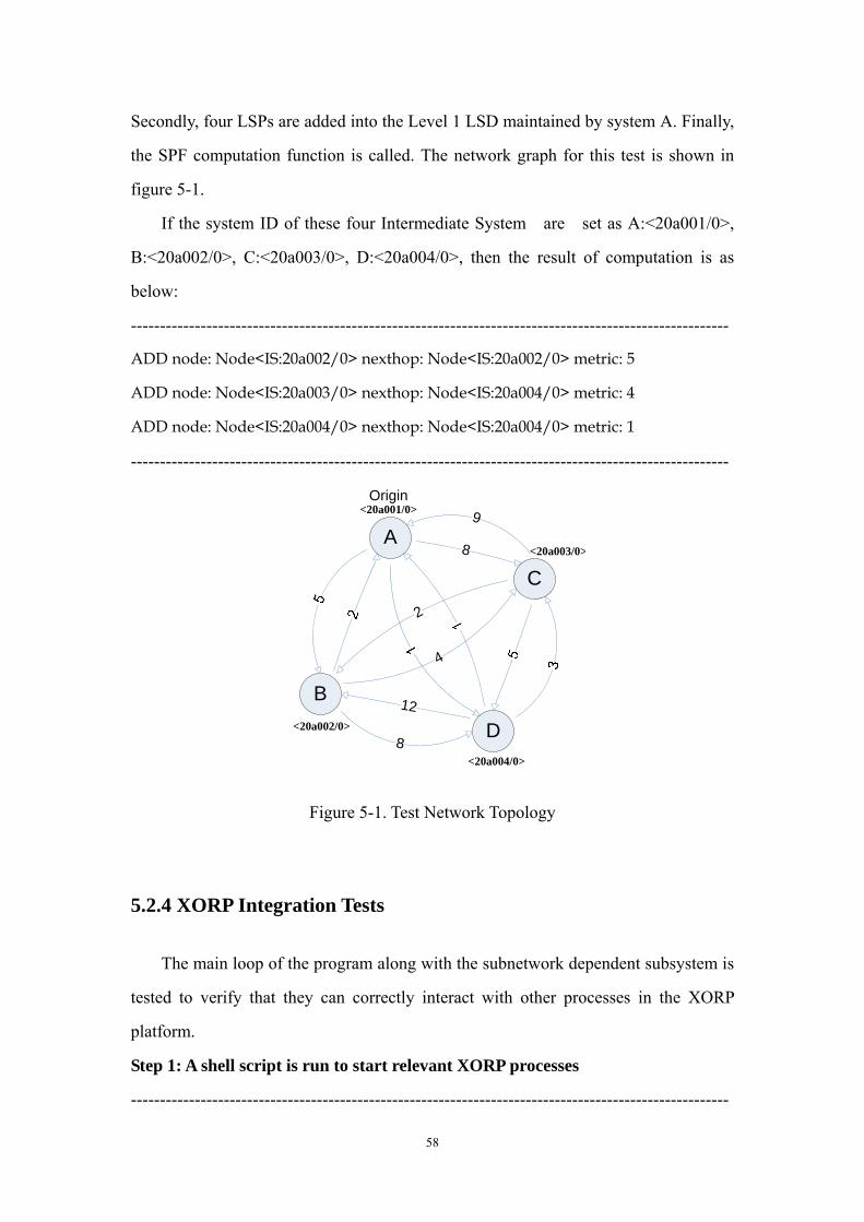
58
Secondly, four LSPs are added into the Level 1 LSD maintained by system A. Finally,
the SPF computation function is called. The network graph for this test is shown in
figure 5-1.
If the system ID of these four Intermediate System are set as A:<20a001/0>,
B:<20a002/0>, C:<20a003/0>, D:<20a004/0>, then the result of computation is as
below:
-------------------------------------------------------------------------------------------------------
ADD node: Node<IS:20a002/0> nexthop: Node<IS:20a002/0> metric: 5
ADD node: Node<IS:20a003/0> nexthop: Node<IS:20a004/0> metric: 4
ADD node: Node<IS:20a004/0> nexthop: Node<IS:20a004/0> metric: 1
-------------------------------------------------------------------------------------------------------
A
D
C
B 12
8
9
2
4
8
Origin<20a001/0>
<20a003/0>
<20a002/0>
<20a004/0>
Figure 5-1. Test Network Topology
5.2.4 XORP Integration Tests
The main loop of the program along with the subnetwork dependent subsystem is
tested to verify that they can correctly interact with other processes in the XORP
platform.
Step 1: A shell script is run to start relevant XORP processes
-------------------------------------------------------------------------------------------------------

59
Port number for the xorp_finder= 12345 Setting port... Starting xorp_finder... Starting xorp_fea... Starting xorp_rib... > [ 2005/09/02 05:03:03 INFO xorp_fea CLI ] CLI enabled [ 2005/09/02 05:03:03 INFO xorp_fea CLI ] CLI started [ 2005/09/02 05:03:03 INFO xorp_fea MFEA ] MFEA enabled [ 2005/09/02 05:03:03 INFO xorp_fea MFEA ] CLI enabled [ 2005/09/02 05:03:03 INFO xorp_fea MFEA ] CLI started [ 2005/09/02 05:03:03 INFO xorp_fea MFEA ] MFEA enabled [ 2005/09/02 05:03:03 INFO xorp_fea MFEA ] CLI enabled [ 2005/09/02 05:03:03 INFO xorp_fea MFEA ] CLI started
-------------------------------------------------------------------------------------------------------
The Finder, the FEA and the RIB daemons are all started with the finder port
manually input.
Step 2: A shell script is run to configure the FEA
------------------------------------------------------------------------------------------------------- configure_interface_from_system 738664 vr0 create_vif 738664 vr0 vr0 enable_vif 738664 vr0 vr0 commit_transaction get_system_interface_namesifnames:list=:txt=dc0,:txt=faith0,:txt=lo0,:txt=ppp0,:txt=sl0,:txt=vr0 get_configured_interface_namesifnames:list=:txt=vr0 get_system_vif_names vr0vifs:list=:txt=vr0 get_configured_vif_names vr0vifs:list=:txt=vr0
-------------------------------------------------------------------------------------------------------
A series of XRLs are called to configure the system interfaces for the FEA, which
are all self-explanatory by the function names.
Step 3: Run the IS-IS process
------------------------------------------------------------------------------------------------------- [ 78397 +103 xorp_isis_main.cc ] Isis started. [ 78397 +82 xorp_isis_main.cc ] Default Finder_host:127.0.0.1/Default Finder_port:19999 [ 78397 +57 xrl_circuit_manager.cc ] XrlCircuitManager created. [ 78397 +23 xrl_target_isis.cc ] XrlIsisTarget created. [ 78397 +281 xrl_circuit_manager.cc ] XrlCircuitManager::tree_complete

60
notification. [ 78397 +133 isis_circuit_manager.hh ] circuits update from XrlCircuitManager.
-------------------------------------------------------------------------------------------------------
The IS-IS process is started and relevant components are created. Since the
XrlCircuitManager acts as a remote mirror, it is notified by the FEA with
“tree_complete notification” once started.
Step 4: Configure an interface for the IS-IS process
------------------------------------------------------------------------------------------------------- (Configuration command) ./call_xrl "finder://isis/isis/0.1/set_system_id?id:ipv4=192.164.160.88" (Response of the IS-IS process) [ 78397 +71 xrl_target_isis.cc ] System ID updated to 192.164.160.88 (Configuration command) ./call_xrl "finder://isis/isis/0.1/add_area_address?addr:u32=56890" (Response of the IS-IS process) [ 78397 +88 xrl_target_isis.cc ] Area address de3a added.
(Configuration command)
./call_xrl
'finder://isis/isis/0.1/configure_interface?ifname:txt=vr0&vif:txt=vr0&level:u32=1
&enable:bool=true&passive:bool=false&metric:u32=10&hello_interval:u32=100&hol
d_time_multiplier:u32=3&priority:u32=64'
(Response of the IS-IS process)
[ 78397 +117 xrl_target_isis.cc ] Configure interface:vr0/vr0 to:level 1;enable 1;passive 0; metric 10;hello_interval 100;hold_time_multiplier 3;priority 64. [ 78397 +120 xrl_circuit_manager.cc ] Configure interface:vr0/vr0 to:level 1;enable 1;metric 10;hello_interval 100;hold_time_multiplier 3;priority 64. [ 78397 +24 xrl_circuit_manager.cc ] Looking for vr0/vr0 [ 78397 +38 xrl_circuit_manager.cc ] Found [ 78397 +178 xrl_circuit_manager.cc ] Creating new Lan circuit with id 2 [ 78397 +393 isis_circuit.cc LANCircuit ] LANCircuit vr0/vr0/2 created. start_iih_timer... send_iih()... [ 78397 +40 xrl_circuit_io.cc send ] packet is sending to FEA ... [ 78336 +2509 xrl_target.cc ] Send IS-IS packet; To Mac address: 00:01:02:03:04:05. [ 78336 +2513 xrl_target.cc ] Size of the packet:49

61
[ 78336 +2514 xrl_target.cc ] Content of the packet: 083a0150 831b 0100 0f01 0000 0102 00c0 a4a0 5801 ..............X. 083a0160 2c00 3140 0000 0001 0000 0001 0e0d 4700 ,[email protected]. 083a0170 0580 0000 a700 00de 3a00 0084 0480 1042 ........:......B 083a0180 5f _ [ 78397 +80 xrl_circuit_io.cc send_cb ] SendCB 100 Okay
-------------------------------------------------------------------------------------------------------
We can see from this test that the IS-IS process can correctly receive the
configuration requests via XRLs, and once an interface is configured for IS-IS, a
Circuit object is created and starts to send out Hello packets periodically.
5.3 Overall System Testing
After the major components have been verified to work properly and some
integration for part of the system has been carried out, the next step would be to test
how the routing process works as a whole. We planned to use an existing simulation
framework developed by Adam Barr which can simulate a network consisting of
multiple routers by running multiple IS-IS instances on a single machine (as shown in
figure 5-2).
The simulation framework mainly involves two aspects and is related to the
modifications of the FEA we mentioned before.
One major function of the framework is to create simulated interfaces. In order to
emulate a network, we first need to emulate some routers, each of which has multiple
interfaces. The existing dummy FEA in XORP provides interfaces for us to manually
create and configure virtual interfaces via XRLs for testing purposes. The simulation
framework provides a similar but more convenient function—the FEA can read from
interface state files that have very simple format and create spoofing interfaces
accordingly. This function is implemented by adding an interface state file loader into
the FEA.
Another important function provided by the simulation framework is to transmit
packets between virtual IS-IS routers. A virtual IS-IS router is represented by a set of
XORP processes: the Finder, the simulation FEA, the RIB and the IS-IS routing
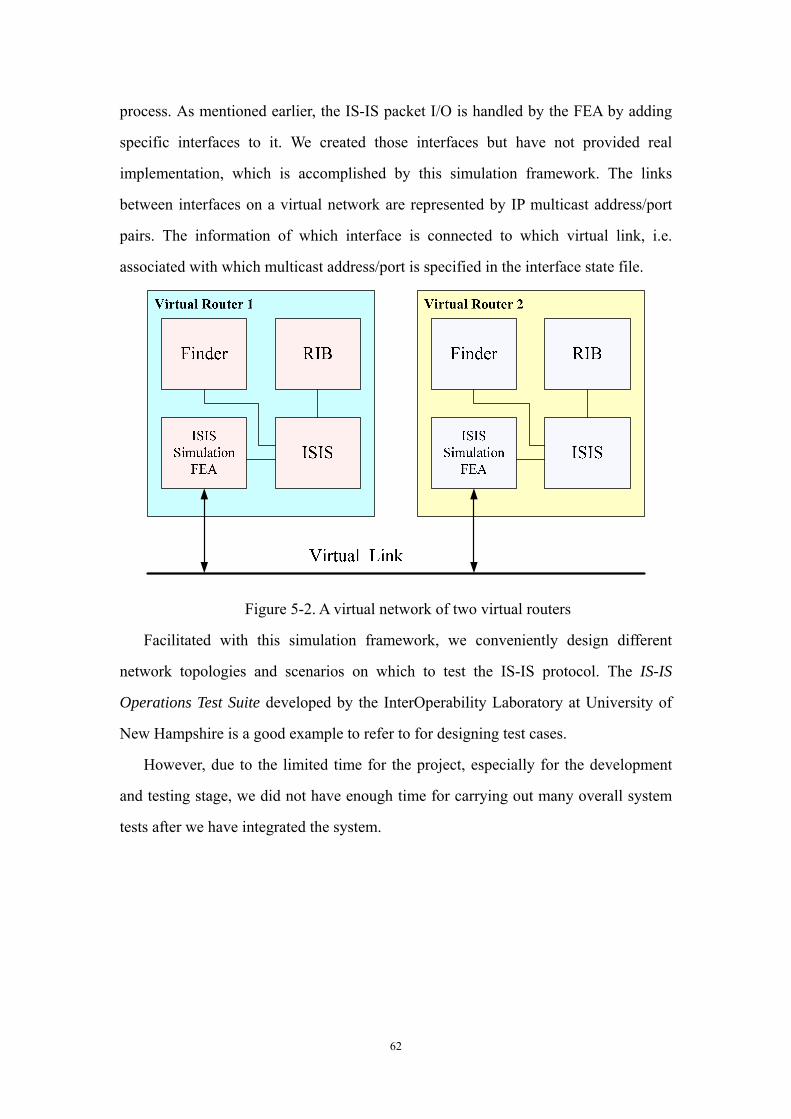
62
process. As mentioned earlier, the IS-IS packet I/O is handled by the FEA by adding
specific interfaces to it. We created those interfaces but have not provided real
implementation, which is accomplished by this simulation framework. The links
between interfaces on a virtual network are represented by IP multicast address/port
pairs. The information of which interface is connected to which virtual link, i.e.
associated with which multicast address/port is specified in the interface state file.
Figure 5-2. A virtual network of two virtual routers
Facilitated with this simulation framework, we conveniently design different
network topologies and scenarios on which to test the IS-IS protocol. The IS-IS
Operations Test Suite developed by the InterOperability Laboratory at University of
New Hampshire is a good example to refer to for designing test cases.
However, due to the limited time for the project, especially for the development
and testing stage, we did not have enough time for carrying out many overall system
tests after we have integrated the system.

63
Chapter 8: Project Management
Since this is a group project, it is necessary that we use appropriate project
management techniques to plan, monitor and maintain progress, as well as to assign
different tasks to group members and coordinate the group activities.
8.1 Project Management Plan
According to the nature and characteristics of this project, we decided the project
management plan we were going to adopt at the beginning of the project. First of all,
we decided it would not be very appropriate for us to use an agile approach such as
XP Programming. Agile approaches emphasise on iterative and incremental
development, along with small iterations and releases. Such approaches are quite
popular in software engineering and have a lot of advantages. For example, XP
Programming techniques allow for constant refinement of requirements and provide
continuous feedback from earlier development cycles. Therefore, XP Programming is
best for the kind of project in which the requirements are not clearly defined at the
beginning or are likely to be changed continually throughout the process of the project.
However, in the case of our project, the primary requirements are very clearly and
extensively defined in relevant specifications and are not likely to change. In addition,
the scale of the IS-IS system and the time we have for the project together has
determined that it would be unrealistic to plan for multiple iterations and releases
because the whole project should be seen as the first iteration of providing an
operational IS-IS implementation for the XORP platform, and we only expected a first
release.
Therefore, the project management plan we chose to use is more like the
traditional waterfall model, which typically has four major stages: requirement
analysis, system design, implementation and testing. In addition, we also decided that
although it would not be advisable for us to adopt a formal iterative and incremental
approach completely, there are some ideas and techniques in this type of plans that we

64
could make use of in order to improve our development and mitigate risks. For
example, although we cannot have multiple iterations, we can apply the idea of
continuous feedback to different components. The most basic and fundamental
components which other components depend on would be implemented and tested
first, during which some problems may be discovered and trigger the revision and
improvements of the architecture design as well as the individual module design. This
decision was also made because it would enable us to gain valuable experience in
actual coding and testing during the early developments. Although the
implementations for individual components are likely to be very different, the
requirements for programming knowledge and skills would inevitably have something
in common, therefore, this method would hopefully make the later developments
faster and more reliable. Moreover, we integrate a small part of the system once some
components are finished and become available instead of leaving all the integration to
the final stage of the project, which helps discover the bugs in individual components
earlier and therefore makes it easier to fix them gradually. Figure 8-1 gives a general
idea of our development process as time evolves.
Figure 8-1. Illustration of Development Process
8.2 Work Breakdown
As suggested in our earlier Project Management course module, we designed
very detailed work breakdown structure which breaks the whole project work down
Implementing module 1
Implementing module 2
Implementing module 3
Time
Testing module 1
Testing module 2
Testing module 3
Integration
Integration
Integration

65
into smaller tasks that can be undertaken by individual group members. Figure 8-1
shows only the summary structure.
Figure 8-2. Work Breakdown Structure
8.3 Team Organisation
The project is carried out under the supervision of Professor Mark Handley, and
he acts as both the client of the project and our advisor. The group itself consists of
five people, and the initial roles of individual group members were agreed at the
beginning of the project after group discussion:
-- Project Manager: Ling Zhen
-- Design Engineer: Bitao Sun
-- Test Engineer: Xin Xiong

66
-- Configuration manager: Kang Tang
-- Risk and progress manager: Hongyi Li
However, since the team members do not have particular advantages over others
in these aspects of a project, we were not clear at the beginning that how suitable this
assignment of roles and responsibilities would be. Therefore, we also decided that the
roles and responsibilities of team members should not be fixed, but should be
adaptable according to suitability. Also, the roles of group members should be flexible
considering the progress of the project, for example, when difficulties are encountered
in some high priority tasks which might not be able to be finished within the planned
time, more people may be assigned to help with those tasks. The roles of group
members may also be rotated in order for us to learn about all aspects of the project.
As the project evolves, we have made some adjustments to the work dividing
decisions. At the beginning stage of the project, we decided that one member should
be responsible for getting familiar with the environment and configuration relevant
issues on the XORP platform (Ling was assigned to this task), while others should
read the extensive specifications about the IS-IS routing protocol and understand its
internal structure and operations.
After the system architecture design (mainly done by Bitao and agreed by the
group) was finished, the system is divided into two major parts which are relatively
independent of each other. One part mainly consists of LSDManager, LSD, SPF
Calculation and XrlRibNotifier modules, and the other mainly consists of
CircuitManager, Circuit, CircuitIO and Adjacency modules. Therefore, the group was
divided into two sub-groups with two persons each. Kang and Xin would mainly work
on the former part, and Bitao and Hongyi on the latter. And Ling would work on the
packet encoder/decoder module, the pieces connecting the above two parts and some
XORP integration pieces. Having made such arrangements, we felt that it would be
more feasible and efficient for each member to take responsibilities for the design,
coding and testing of the modules they work on because it would take more time for
others to learn about the modules they are not familiar with.
In the final documentation stage of the project, every member was responsible for

67
writing about the part they had been working on and Ling integrated all these
documentations into the group report.
8.4 Monitor and Control
Carrying out effective measurements to monitor and control the progress of the
project is important because it enables us to be aware of the up-to-date status of the
project, to compare the actual progress with planned and to make appropriate
adjustments accordingly.
The project manager is generally responsible for overseeing the progress of the
project. Regular internal reports including progress report and issue log are produced
on a daily/weekly basis. Actual progress is compared to the planned schedule and if it
is lagging behind, the schedule would have to be adjusted.
The group has regularly meetings with our supervisor on a weekly basis. On
every meeting, we discuss the problems we have encountered both in technical and
project management aspects and seek advice and opinions from the supervisor. Some
documents such as design diagrams and related materials are prepared when
necessary to facilitate the discussions. Sometimes we have more than one meeting per
week when problems and confusions occur more frequently especially at the
beginning of the development stage, and we also seek help from the supervisor on
more specific problems individually every now and then. Thanks to the great
guidance of our supervisor, we have been able to solve most of the problems in time.
Meeting minutes are taken to make sure we have understood the problems and
relevant resolutions, which group members can refer to whenever necessary. They
also serve as an important documentation for recording the evolution of the project.
Communications within the group happen in a number of ways. It is suggested to
meet every weekday and work together in the labs so that problems can be discussed
and solved by short meetings more efficiently. A group mailing list is created to
update members with each other’s development status and for various discussions. In
addition, a CVS repository is created for the project, so that we can keep track of the

68
development progress and have access to the modification history. The CVS is also
beneficial in that it enables group members to continuously check the interfaces
provided by one another’s modules and therefore makes the integration of different
components easier.
8.5 Risk Management
We have identified a number of potential risks and corresponding mitigation
strategies.
Description Priority Mitigation Strategy Bad design High − Incremental Iterative Development
− Continuous integration
− Simple design
− Feedback
Configuration problems
Low − Assign a group member to take charge before actual work begins
Progress not according to schedule
Moderate − Progress tracking (daily work check and keep a work log)
− Learn from mistakes that cause delay
− Teamwork
Absence of supervisor
Moderate − Keep in touch with email − Project schedule should be more tightly
− Work extra hours
Insufficient materials
Moderate − Ask supervisor for information
− Check the internet frequently
Absence of team members
Low − Keep in Constant Communication
− Inform team and keep track of absence well in advance
Data loss Low − Back up everyone’s own work daily in their own machine
and CS directory
− Project manager backs up the whole work on CS machines
Lack of developing experiences
Low − Self study
− Learn from other groupmates

69
Chapter 9: Future Work and Conclusion
9.1 Future Work
Due to the time constraints of the project, there exist some possible enhancements
and extensions to the work we have accomplished.
First, the implementation can be extended to support both IPv4 and IPv6.
Existing XORP routing protocols provide support for both IPv4 and IPv6 by using
template classes in the C++ Standard Template Library. In our project, only the
XrlRibNotifier module uses this feature to adapt to both types of IP address, the rest of
the system is specifically developed for IPv4. Therefore, some work can be done to
add the template usage to the system in order to add the support for IPv6. Most of the
specific routing functions would not have to be modified because IS-IS is a quite
flexible routing protocol and does not need to be changed much itself for supporting
IPv6 or even new network layer protocols.
Second, proper integration testing should be carried out for the system either
based on the existing simulation framework or by developing a new simulation
framework. Since the existing simulation framework is known to work well, it might
be more desirable to make further modifications to the FEA for reading and writing
IS-IS frames from and to the wire so that the protocol could be tested on the real
network.
Additionally, some possible extensions which have been considered as optional
functions defined in RFC 1142 and RFC 1195 can be further implemented. These
functions include: partition repair, authentication, hierarchical abbreviation of IP
reachability information and so forth.
9.2 Conclusion
The primary objective of the project that we set out to fulfil is to provide an IS-IS
implementation including the core functionalities for the XORP platform. The project

70
can be considered to be an overall success because we have basically achieved our
goal.
Firstly, we have designed a sensible system architecture by which the structure of
the IS-IS routing protocol is properly reflected. This system architecture has proved to
be beneficial during the implementation of individual components. It is an important
achievement in developing a complex system because it provides a solid basis for
potential extensions and improvements in the future.
Secondly, we have implemented a complete set of core functions defined by the
relevant specifications and performed proper tests to verify the correct behaviours of
all components, which means we have successful achieved the goal of the project.
Although enhancements can definitely be made to improve the performance of the
system, such non-functional requirements are not within the scope of our project. In
addition, our IS-IS system is integrated into the XORP platform properly. The XORP
integration parts have been thoroughly tested and work well, which is also important
groundwork for possible future extensions.
Although the time has not allowed us to do many tests for the overall system to
make sure it works without problems, since individual components have been
properly tested and system integration has been done successfully, it is less likely that
major problems would occur when the system is tested as a whole.
This project has been a challenge for us, and we have learned a great deal in this
process. We have learned and worked on the XORP platform, and have therefore
become familiar with this young and lively research project. The design choices made
for XORP in order to achieve its goals of extensibility, robustness and performance
have given us a valuable lesson in system architecture design. We have also learned a
great amount of knowledge about the operations of routing protocols, not only IS-IS
but also OSPF and RIP; and we have gained valuable experiences in C++
programming, especially in using the Standard Template Library. All of these would
be continuously beneficial for either our further study and research or professional
careers in the future.

71
Bibliography
[1] XORP - Open Source IP Router, April 2005. http://www.xorp.org
[2] D. Oran. OSI IS-IS Intra-domain Routing Protocol, RFC 1142.
[3] R. Callon. Use of OSI IS-IS for routing in TCP/IP and dual environments,
RFC1195
[4] Adam Barr. An Intermediate System to Intermediate System (ISIS) Implementation
for the eXtensible Open Router Platform (XORP)
[5] Cisco Systems. Introduction to Intermediate System to Intermediate System
Protocol. 2002.
[6] XORP Design Overview. http://www.xorp.org.
[7] M. Handley, E. Kohler, A. Ghosh, O. Hodson, and P. Radoslavov. Designing.
Extensible IP Router Software. In Proceedings of the 2nd USENIX Symposium
on Networked Systems Design and Implementation (NSDI), 2005.
[8] M. Handley, O. Hodson, and E. Kohler. XORP: An Open Platform for Network
Research. In First Workshop on Hot Topics in Networks, Princeton, New Jersey,
2002.
[9] M. Handley. Introduction to Writing a XORP Process. http://www.xorp.org, 2004.
[10] Intermediate System to Intermediate System (IS-IS) Operations Test Suite,
Revision 4.3. Technical report, IPv4 Consortium, InterOperability Laboratory,
Research Computing Center, University of New Hampshire, 2005.
[11] Jeff Doyle, Routing TCP/IP , Volume 1, 1998, Cisco Press
[12] Open Source Development Network. SourceForge.net. http://sourceforge. net/.
[13] R. Perlman. Interconnections: Bridges, Routers, Switches and Internetworking
Protocols. Addison-Wesley, 2000. Second edition.

![A Novel Hybrid Routing Protocol for Mobile Adhoc Network · A Novel Hybrid Routing Protocol for Mobile Adhoc Network ... routing overhead, ... Reactive routing protocol [2, 8, 9]](https://img.dokumen.tips/doc/110x75/5ac806c47f8b9a42358bf340/a-novel-hybrid-routing-protocol-for-mobile-adhoc-network-novel-hybrid-routing-protocol.jpg)