Embed Size (px)
Citation preview
IMPLEMENTATION OF APC ON REPSOL PUERTOLLANO CDU 1
Julián Ochoa Fuentes
José Acedo Sánchez
María José Acedo López
Amelia Riestra López
Ana Alcalde Báscones
James Hall
Y. Zak Friedman
ERTC Computer Conference, May 2007
Puertollano CDU paper, Page 1
IMPLEMENTATION OF APC ON REPSOL PUERTOLLANO CDU1 Introduction (slide 2) In this paper, the implementation of a new multivariable process controller (MVPC) for Crude
Distillation Unit 1 at Repsol YPF refinery in Puertollano is presented. The paper reviews the
improvements generated from this work, in two aspects: better product quality control using
GCC inferencial model, and enhanced operation and control of the unit achieved with the new
MVPC.
Repsol YPF and Puertollano refinery site (slides 3 and 4) Repsol YPF is an international integrated oil and gas company, operating in over 30 countries.
The installed refining capacity of the company is 1.2 MM bpd, 70% of it is installed in Spain
and the rest in several South American countries.
Repsol YPF operates five refineries in Spain. The positioning of Puertollano Industrial
Complex in the center of the peninsula is ideal for covering the fuel product needs of Madrid
and the center area. Puertollano Industrial Complex has a crude oil distillation capacity of 7.5
million tonnes a year. The Puertollano refinery is technically the most complex of all the
Spanish refineries, due to both the product variety and the integration of the units.
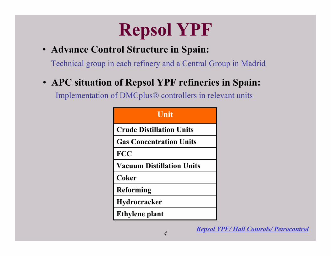
The Advanced Control group responsible for APC in the Repsol YPF spanish refineries is
composed of a central group plus local groups at each refinery site. Nowadays, the efforts of
the group are concentrated on the maintenance of existing multivariable controllers, and the
implementation of new ones in the most relevant units of the refineries.
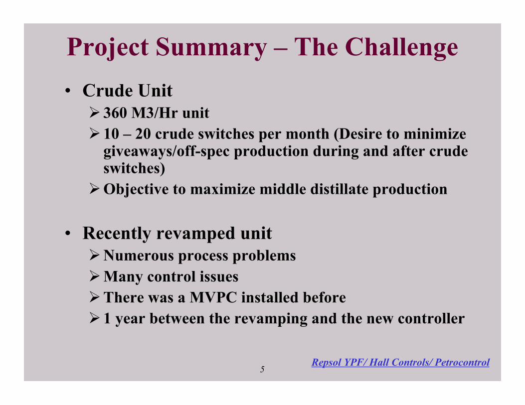
The rational for Puertollano CDU APC (slide 5) Puertollano CDU1 is not a large unit by industry standard, but the unit operational complexity
and frequency of crude switches were enough to justify APC. Puertollano CDU1 has gained
substantial yield improvement and can also gain throughput increases.
It is strange but appropriate to note that further, not insignificant benefit of APC is that it
provides immediacy and focus to get operational problems solved. This was the case at
Puertollano. Many of the problems that hindered APC were not control related, but our
project provided a catalyst to get the problems investigated and solved. The solutions were a

Puertollano CDU paper, Page 2
multi-disciplinary team effort between operations, process, instrumentation, and the advanced
control groups working together.
The Project team (slide 6) As is well known, the key to CDU APC is repeatable inferential models, estimating product
qualities at all times and especially during crude switches. Repsol has elected to work with
the Petrocontrol GCC (Generalized cutpoint calculation) technology. Petrocontrol
implemented GCC together with Repsol technology center engineers as well as Puertollano
engineers.
Hall Controls was selected as the consultant in the design and implementation of the
application. Repsol provided the strong support of a full time engineer.
The application makes use of MVPC (multivariable predictive control software): Aspen
Technology’s DMCplus®, for which Repsol has a site wide license.
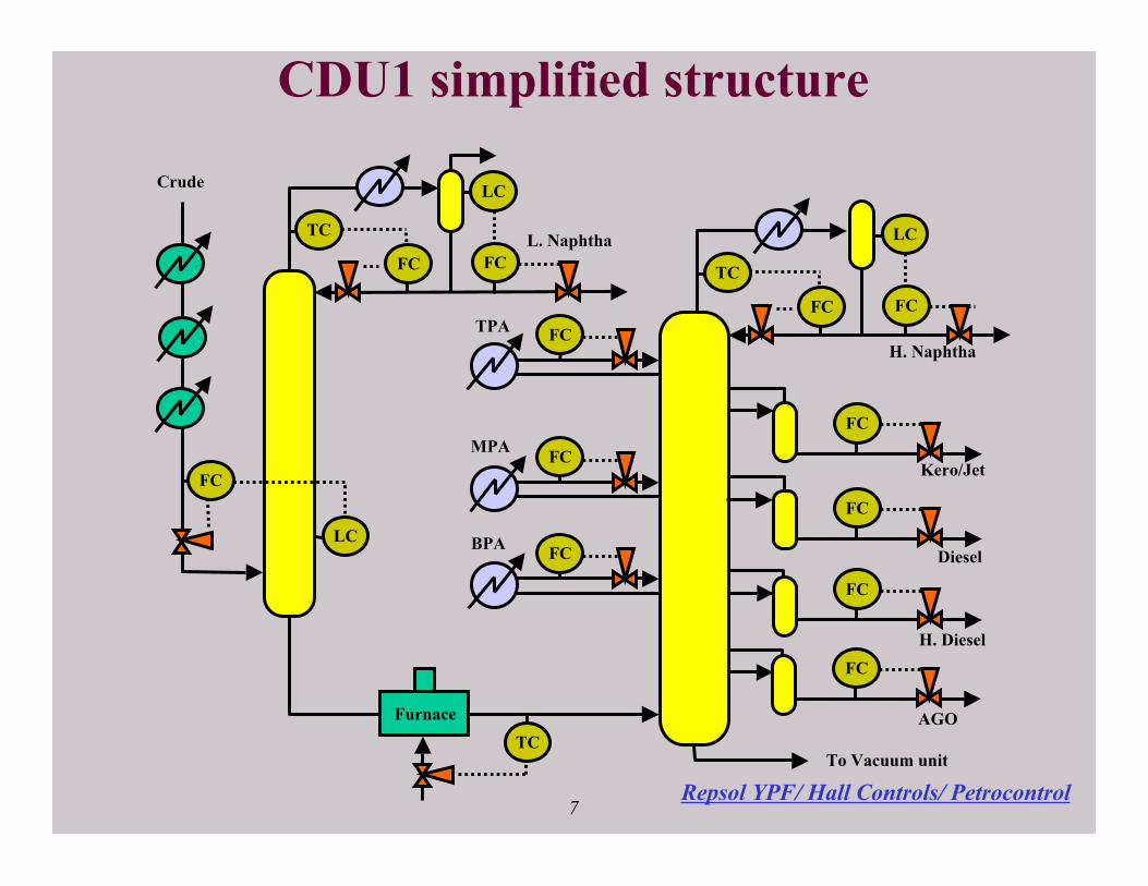
CDU Configuration (slide 7) The unit is configured with a prefractionator, separating out light naphtha, and a main
atmospheric column. The main column separates a top product of heavy naphtha and four
side streams: kero, diesel, heavy diesel and AGO. Commercially the desire is as usual to
maximize the sidestreams to cutpoint specifications.
Light and heavy naphtha are combined and taken through a stabilizer and naphtha splitter.
The main fractionator has four cooling circuits:
• Sub-cooled external reflux returned to the top tray
• Top pumparound (TPA) exchanges heat against crude before the desalter and returned
to the top tray
• Middle pumparound (MPA) exchanges heat against crude after the desalter
• Bottom pumparound (BPA) which supplies heat for the naphtha stabilizer and crude
preheat.
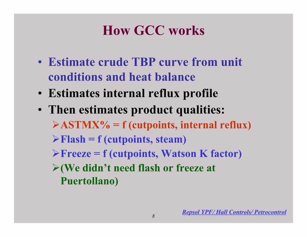
GCC concepts (slide 8) GCC has been described in several papers (1, 2, 3, 4, 5, 6), and time here permits a summary
but not detailed discussion. GCC applies heat balances, mass balances, partial pressure
Puertollano CDU paper, Page 3
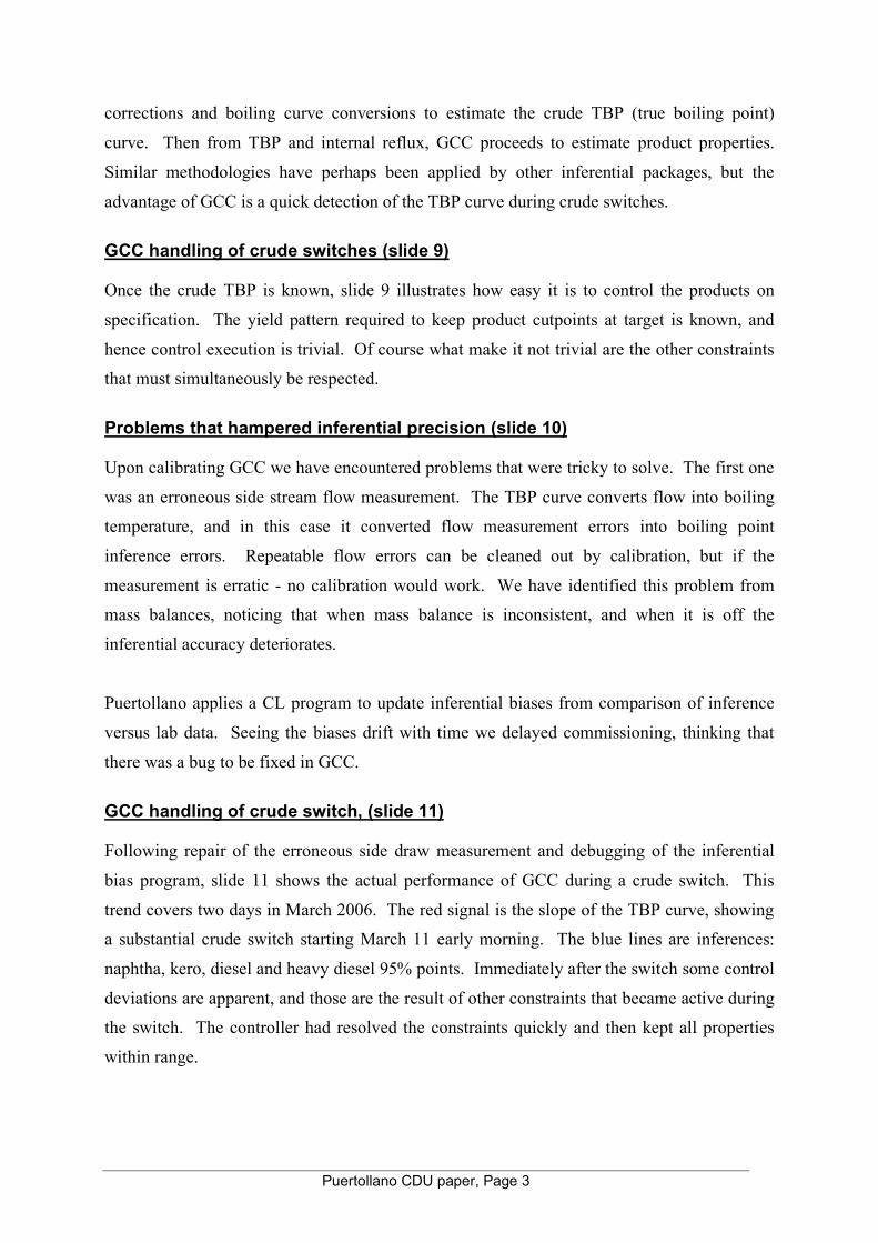
corrections and boiling curve conversions to estimate the crude TBP (true boiling point)
curve. Then from TBP and internal reflux, GCC proceeds to estimate product properties.
Similar methodologies have perhaps been applied by other inferential packages, but the
advantage of GCC is a quick detection of the TBP curve during crude switches.
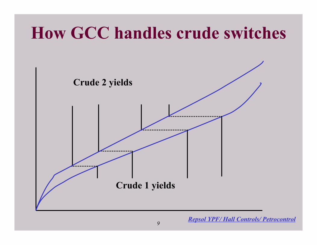
GCC handling of crude switches (slide 9) Once the crude TBP is known, slide 9 illustrates how easy it is to control the products on
specification. The yield pattern required to keep product cutpoints at target is known, and
hence control execution is trivial. Of course what make it not trivial are the other constraints
that must simultaneously be respected.
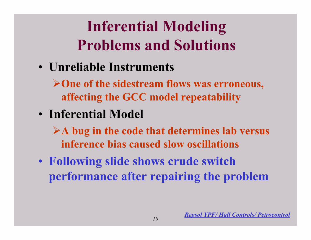
Problems that hampered inferential precision (slide 10) Upon calibrating GCC we have encountered problems that were tricky to solve. The first one
was an erroneous side stream flow measurement. The TBP curve converts flow into boiling
temperature, and in this case it converted flow measurement errors into boiling point
inference errors. Repeatable flow errors can be cleaned out by calibration, but if the
measurement is erratic - no calibration would work. We have identified this problem from
mass balances, noticing that when mass balance is inconsistent, and when it is off the
inferential accuracy deteriorates.
Puertollano applies a CL program to update inferential biases from comparison of inference
versus lab data. Seeing the biases drift with time we delayed commissioning, thinking that
there was a bug to be fixed in GCC.
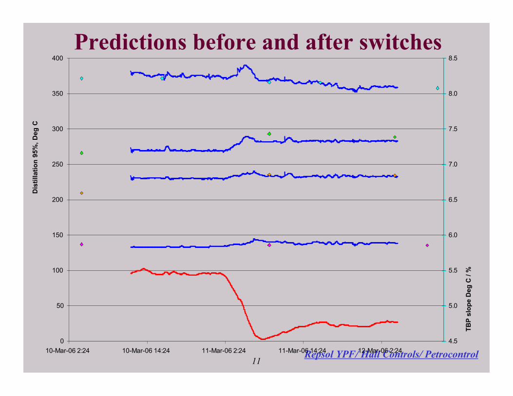
GCC handling of crude switch, (slide 11) Following repair of the erroneous side draw measurement and debugging of the inferential
bias program, slide 11 shows the actual performance of GCC during a crude switch. This
trend covers two days in March 2006. The red signal is the slope of the TBP curve, showing
a substantial crude switch starting March 11 early morning. The blue lines are inferences:
naphtha, kero, diesel and heavy diesel 95% points. Immediately after the switch some control
deviations are apparent, and those are the result of other constraints that became active during
the switch. The controller had resolved the constraints quickly and then kept all properties
within range.
Puertollano CDU paper, Page 4
The diamond shaped dots on slide 11 represent lab tests, three tests for most products and five
for heavy diesel. The consistent fit of GCC versus lab tests before, during and after the crude
switch is clearly demonstrated.
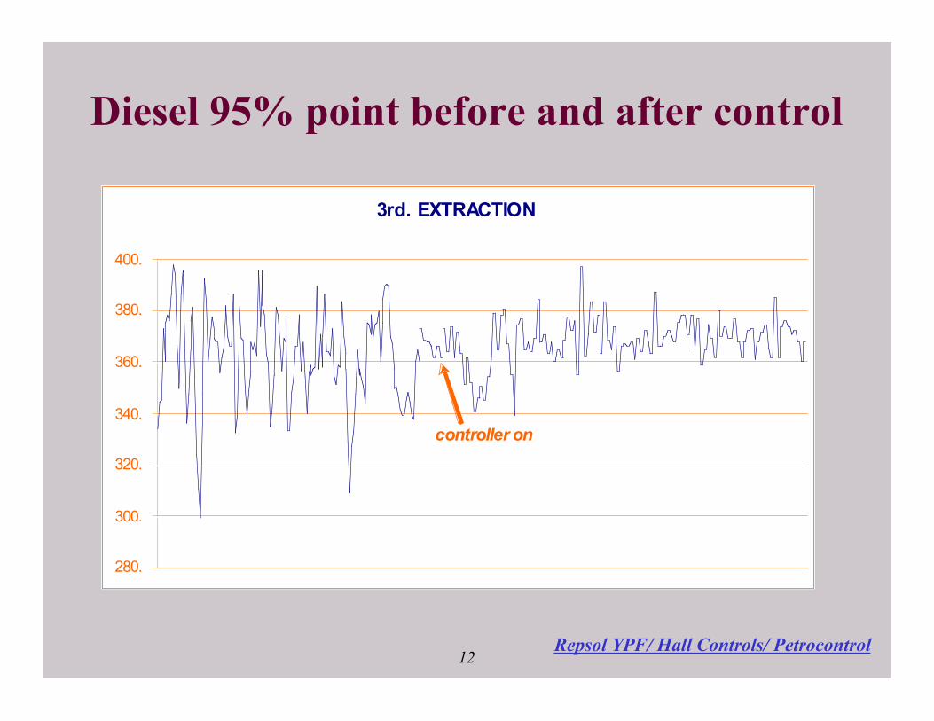
Diesel quality improvement (slides 12) Slide 12 trends one significant key performance indicators for the CDU: heavy diesel 95%
Point. Before implementation of our controller, errors of 30, or even 50°C were not
uncommon, whereas after commissioning the quality control precision has shrunk ten fold.
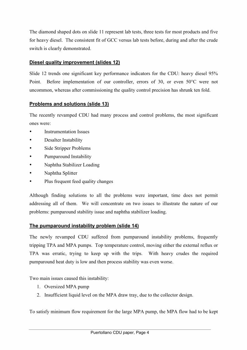
Problems and solutions (slide 13) The recently revamped CDU had many process and control problems, the most significant
ones were:
• Instrumentation Issues
• Desalter Instability
• Side Stripper Problems
• Pumparound Instability
• Naphtha Stabilizer Loading
• Naphtha Splitter
• Plus frequent feed quality changes
Although finding solutions to all the problems were important, time does not permit
addressing all of them. We will concentrate on two issues to illustrate the nature of our
problems: pumparound stability issue and naphtha stabilizer loading.
The pumparound instability problem (slide 14) The newly revamped CDU suffered from pumparound instability problems, frequently
tripping TPA and MPA pumps. Top temperature control, moving either the external reflux or
TPA was erratic, trying to keep up with the trips. With heavy crudes the required
pumparound heat duty is low and then process stability was even worse.
Two main issues caused this instability:
1. Oversized MPA pump
2. Insufficient liquid level on the MPA draw tray, due to the collector design.
To satisfy minimum flow requirement for the large MPA pump, the MPA flow had to be kept
Puertollano CDU paper, Page 5
at a high value. Excessive heat removal in the fractionator middle section would condense
too much liquid, and shortage of liquid at the top section would trip the TPA pump. Further,
lack of liquid on the MPA draw tray often resulted in MPA pump trip. Light diesel product is
taken from the MPA draw, which further complicates the MPA pump suction problem. This
instability in the TPA and MPA rendered overhead temperature control difficult.
Once the problems were understood we set out to solve them.
• The Process design group engineered a hot bypass of the MPA that could be quickly
implemented. The bypass permitted high MPA flow while keeping the heat duty low,
satisfying minimum flow requirement of the oversized pump. The MPA bypass
became a manipulated variable in the MVPC controller.
• We added an MPA suction pressure indication as a controlled variable in the MVPC
controller to ensure that the MPA pump’s net positive suction head (NPSH) was
satisfied.
• The TPA was permanently paired with the top temperature controller. External reflux
was reduced to minimize long term corrosion.
• A heat integration strategy for the pumparounds was added to the MVPC controller to
manage MPA and BPA while respecting the minimum suction pressure constraint,
providing room for the TPA to maintain top temperature control and adequate
fractionation in the upper section of the column. Crude preheat and stabilizer reboiler
requirements are also a part of the pumparound strategy.
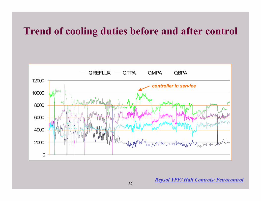
Trend of cooling duties before and after control (slide 15) Slide 15 demonstrates the difference these changes made in stability of the crude unit. Before
the MVPC was in service, frequent trips of the pumparounds are evident. These disturbances
are noticeable even though this slide uses hourly average data. Large movements of heat
duties occur as the top temperature struggled to maintain heat balance. After commissioning
there are fewer trips and much improved operation. Also note that MPA and external reflux
cooling duties have been decreased while BPA heat removal has been generally increased.
This is due to the larger heat consumption of the naphtha stabilizer as loading was increased
to process all available naphtha.
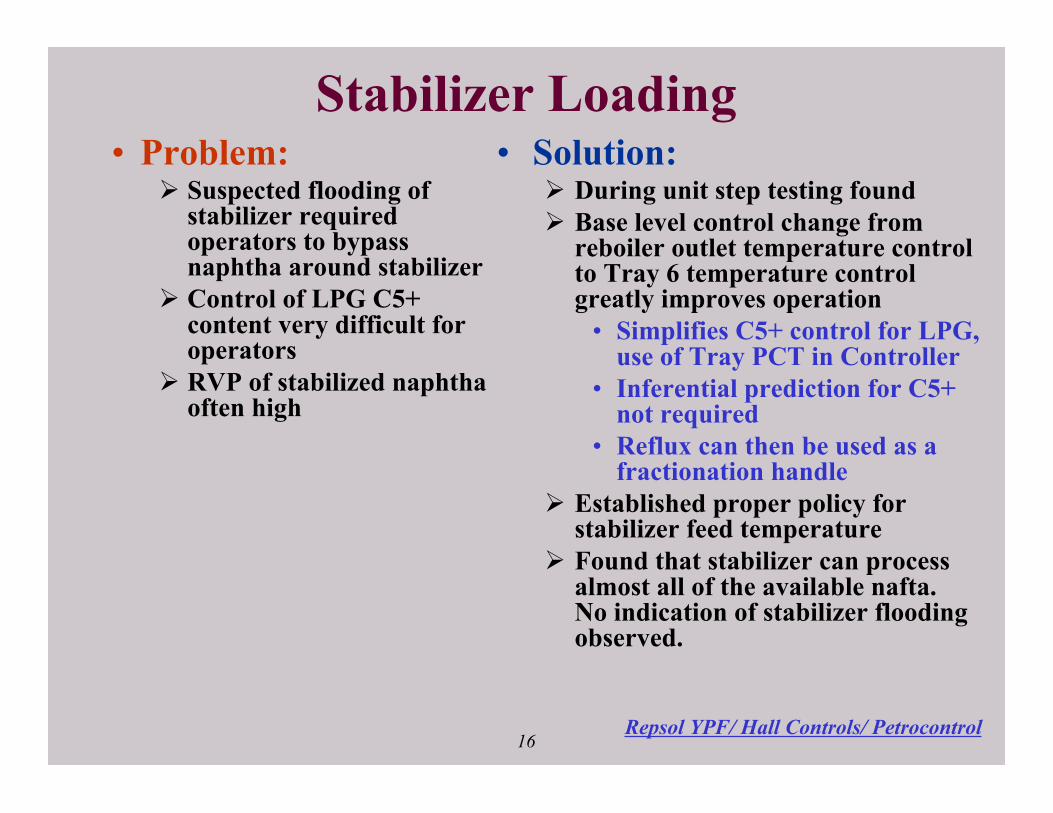
Naphtha Stabilizer Loading problem (slide 16) CDU operators had difficulty keeping LPG C5 content within specification, and stabilized
naphtha RVP often was higher than desired. Column flooding was suspected and to cope

Puertollano CDU paper, Page 6
with this problem operators bypassed atmospheric naphtha around the naphtha stabilizer and
directly to the naphtha splitter. That bypassing has resulted in a loss of LPG recovery.
We investigated stabilizer operation as part of the unit testing for controller dynamic model
identification, with the help of extra laboratory analysis to determine product qualities. It
quickly became apparent that meeting the C5 LPG specification using the existing base level
control scheme was impossible. The base level controls consisted of three PID controllers
for:
• reboiler outlet temperature
• feed temperature
• reflux flow.
Using this configuration, the operators could achieve either:
• essentially no C5’s in LPG but a very high naphtha RVP or
• RVP within limits but high C5’s in LPG.
It was very difficult to operate near the 0.5% C5 in the LPG target with good naphtha RVP
result. Upon seeing a high C5 lab result, the operator would typically bypass more naphtha
around the stabilizer assuming that it was flooded.
We then modified the base level control configuration from a reboiler outlet temperature
controller to a tray 6 temperature controller. Using the control input from a sensible tray
permitted operating near the desired LPG specification. Reflux flow is then manipulated to
fractionate harder and improve the RVP of the stabilized naphtha. The flooding issue turned
out to be a myth.
The MVPC controller was tuned to push fractionation and minimize naphtha RVP while
respecting LPG specification. The stabilizer energy consumption is managed to provide
adequate heat but not at the expense of middle distillate yield in the main column.
Trend of Stabilizer operation before and after control (slide 17) Slide 17 demonstrates the difference in operation before and after the controller was put in
service. The fraction of naphtha processed is now much higher, while the LPG C5 content is
steady near the specification.

Puertollano CDU paper, Page 7
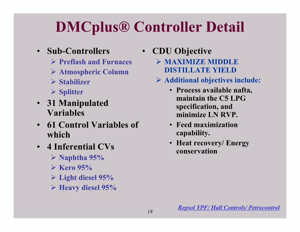
Controller statistics (slide 18) The controller is divided into 4 sub-controllers:
• Preflash and Furnaces
• Atmospheric Column
• Stabilizer
• Splitter.
The sub-controllers allow the independent use of the heater and fractionator control functions
when either is unavailable due to instrumentation or maintenance. The controller has 61
controlled variables and 31 manipulated variables among the sub-controllers. Four inferential
controlled variables are the key to maintaining product specifications during the frequent
crude quality changes. The controller is designed to MAXIMIZE MIDDLE DISTILLATE
YIELD. Available degrees of freedom are consumed by the controller to satisfy additional
objectives:
• Process available naphtha while maintaining the C5 LPG specification and minimize
the light naphtha RVP.
• Feed maximization capability.
• Heat recovery/ Energy conservation.
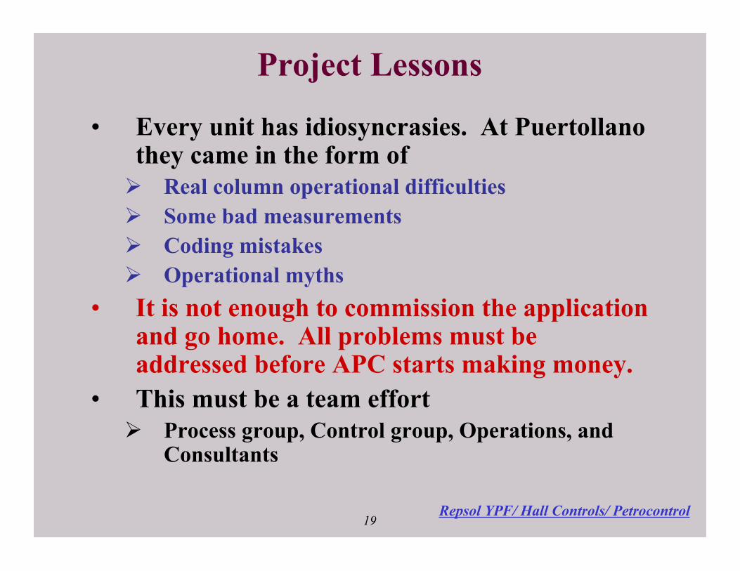
Project Lessons (slide 19) Every unit has idiosyncrasies. At Puertollano CDU they came in the form of:
• Real column operational difficulties
• Some bad measurements
• Coding mistakes
• Operational myths.
It is not enough to commission the application and go home. All problems must be addressed
before APC starts making money. This must be a team effort among available resources
including the Process, Control, Operations departments along with available Consultants.
These lessons are not new.
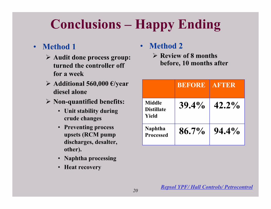
Conclusions (slide 20) Post project APC audit was carried out by the Puertollano process group by turning the
controller off for a week. This exercise has shown an additional refinery profit of 560,000
€/year diesel alone. A comparison of the 8 month period before and 10 month period after
Puertollano CDU paper, Page 8
commissioning of the advanced control shows a 2.8% increase in the yield of middle
distillate. During this same period the total naphtha processed increased 7.7% to 94.4%.
LITERATURE CITED 1. Friedman, Y. Z., “Control of Crude Fractionator Product Qualities during Feedstock Changes
by Use of a Simplified Heat Balance”. American Control Conference, 1985.
2. Friedman, Y. Z., “Crude Unit Advanced Control Experience”. Hydrocarbon processing
Journal, February 1994.
3. Mark Schuler et al, “Refinery uses column data to infer and control product properties”.
NPRA Computer Conference, November 2000, later published in O&G Journal, February
19, 2001.
4. Pradeep Singh et al, “Multivariable Controller Implementation for a Crude Unit: A case
Study”. NPRA Computer Conference, October 2002, later published in O&G Journal,
November 4 2002.
5. Ariffen Adnan, Nyonya Md. Sani, Seung Yun Nam, Y. Zak Friedman, “The use of
first-principles inference models for crude switching control”. ERTC computer
conference, May 2004, later published in PTQ Magazine, Autumn 2004
6. Li Zhen-Guang, Zhi-Qiang Zhang, Zak Friedman, “Implementation of APC on CDU 1 and
CDU 3 at Sinopec Gaoqiao (Shanghai) refinery”. Refining China Conference, April 2006.

1Repsol YPF/ Hall Controls/ Petrocontrol
Implementation of APC onRepsol Puertollano CDU1
James HallY. Zak Friedman
Julián Ochoa FuentesJosé Acedo Sánchez
María José Acedo LópezAmelia Riestra López
Ana Alcalde Báscones

2Repsol YPF/ Hall Controls/ Petrocontrol
Overview• Puertollano Refinery CDU1 Project
Summary• Product Quality Measurement
Problems and Solutions• Process and Control Problems and
Solutions• Project Lessons• Happy Ending

3Repsol YPF/ Hall Controls/ Petrocontrol
Repsol YPF• Integrated company: upstream, downstream, petrochemicals, gas• Repsol YPF downstream activities regionally based in
Europe and South-America• 9 refineries operated:
5 refineries in Spain
• Refining capacity: 1.2 million bbl/day• Puertollano refinery site: 7.5 M tons/year Strategic central location High complexity Cartagena
Puertollano
BilbaoCoruña
Tarragona
Spain 740 kb/d (59%)
Conversion FCC eq.: 42%
4Repsol YPF/ Hall Controls/ Petrocontrol
Repsol YPF
• APC situation of Repsol YPF refineries in Spain: Implementation of DMCplus® controllers in relevant units
Ethylene plantHydrocrackerReformingCokerVacuum Distillation UnitsFCCGas Concentration UnitsCrude Distillation Units
Unit
• Advance Control Structure in Spain:Technical group in each refinery and a Central Group in Madrid
5Repsol YPF/ Hall Controls/ Petrocontrol
Project Summary – The Challenge• Crude Unit
360 M3/Hr unit10 – 20 crude switches per month (Desire to minimize
giveaways/off-spec production during and after crudeswitches)
Objective to maximize middle distillate production
• Recently revamped unitNumerous process problemsMany control issuesThere was a MVPC installed before1 year between the revamping and the new controller

6Repsol YPF/ Hall Controls/ Petrocontrol
Project Summary -The Team• Inferentials
Zak Friedman and engineers from TechnologyCenter in Madrid and Puertollano Refinery
Petrocontrol selected for inferential model GCC(Generalized cutpoint calculation) known to workduring crude switches
• ControlJim Hall and engineers from Puertollano Refinery
and from Central GroupHall Controls selected on the basis of prior good
experience at Repsol• Multivariable Software
Aspen Technology’s DMCplus®
7Repsol YPF/ Hall Controls/ Petrocontrol
CDU1 simplified structure
FurnaceTC
FC
Kero/Jet
Diesel
To Vacuum unit
FCTPA
FCBPA
FC
H. Diesel
FC
FCMPA
TC
H. Naphtha
FC
LC
FC
TC L. NaphthaFC
LC
FC
FC
LC
Crude
AGO
FC
8Repsol YPF/ Hall Controls/ Petrocontrol
How GCC works
• Estimate crude TBP curve from unitconditions and heat balance
• Estimates internal reflux profile• Then estimates product qualities:
ASTMX% = f (cutpoints, internal reflux)Flash = f (cutpoints, steam)Freeze = f (cutpoints, Watson K factor)(We didn’t need flash or freeze at
Puertollano)
9Repsol YPF/ Hall Controls/ Petrocontrol
How GCC handles crude switches
Crude 1 yields
Crude 2 yields
10Repsol YPF/ Hall Controls/ Petrocontrol
Inferential ModelingProblems and Solutions
• Unreliable InstrumentsOne of the sidestream flows was erroneous,
affecting the GCC model repeatability• Inferential Model
A bug in the code that determines lab versusinference bias caused slow oscillations
• Following slide shows crude switchperformance after repairing the problem
11Repsol YPF/ Hall Controls/ Petrocontrol
Predictions before and after switches
0
50
100
150
200
250
300
350
400
10-Mar-06 2:24 10-Mar-06 14:24 11-Mar-06 2:24 11-Mar-06 14:24 12-Mar-06 2:24
Dis
till
ati
on
95
%,
De
g C
4.5
5.0
5.5
6.0
6.5
7.0
7.5
8.0
8.5
TB
P s
lop
e D
eg
C /
%
12Repsol YPF/ Hall Controls/ Petrocontrol
Diesel 95% point before and after control
3rd. EXTRACTION
280.
300.
320.
340.
360.
380.
400.
controller on

13Repsol YPF/ Hall Controls/ Petrocontrol
Process and Problems and Solutions
• Many ProblemsInstrumentation IssuesDesalter Instability Side Stripper Problems Pumparound Instability Naphtha Stabilizer Loading Naphtha Splitter Plus frequent feed quality changes
14Repsol YPF/ Hall Controls/ Petrocontrol
Pumparound Instability• Problem:
Large MPA pump withinsufficient liquid level ondraw tray resulted
• Frequent trips of MPApump
• Too much heat removalin MPA causedinstability with TPA.
• Solution: Fixes:
• Implemented bypass ofMPA, use as manipulatedvariable in DMCplus®
• Implemented MPA pumpsuction pressure ascontrolled variable inDMCplus® controller
• Controller manages MPAand BPA to trade- offcrude preheat andmaintain fractionation
Following is a trend of cooling circuit heat duties before andafter control implementation.
QREFLUX, QTPA, QMPA, QBPA
15Repsol YPF/ Hall Controls/ Petrocontrol
Trend of cooling duties before and after control
0
2000
4000
6000
8000
10000
12000
QREFLUX QTPA QMPA QBPA
controller in service
16Repsol YPF/ Hall Controls/ Petrocontrol
Stabilizer Loading• Problem:
Suspected flooding ofstabilizer requiredoperators to bypassnaphtha around stabilizer
Control of LPG C5+content very difficult foroperators
RVP of stabilized naphthaoften high
• Solution: During unit step testing found Base level control change from
reboiler outlet temperature controlto Tray 6 temperature controlgreatly improves operation
• Simplifies C5+ control for LPG,use of Tray PCT in Controller
• Inferential prediction for C5+not required
• Reflux can then be used as afractionation handle
Established proper policy forstabilizer feed temperature
Found that stabilizer can processalmost all of the available nafta.No indication of stabilizer floodingobserved.

17Repsol YPF/ Hall Controls/ Petrocontrol
Stabilizer before and after control
35
45
55
65
75
85
95
105
4/8/2005 0:00 7/17/2005 0:00 10/25/2005 0:00 2/2/2006 0:00 5/13/2006 0:00 8/21/2006 0:00
Nap
hth
a P
rocessed
(%
)
0
1
2
3
4
5
C5 in
LP
G (
%)
Control ON % Naphtha Processed LPG_C5
18Repsol YPF/ Hall Controls/ Petrocontrol
DMCplus® Controller Detail• Sub-Controllers
Preflash and Furnaces Atmospheric Column Stabilizer Splitter
• 31 ManipulatedVariables
• 61 Control Variables ofwhich
• 4 Inferential CVs Naphtha 95% Kero 95% Light diesel 95% Heavy diesel 95%
• CDU Objective MAXIMIZE MIDDLE
DISTILLATE YIELD Additional objectives include:
• Process available nafta,maintain the C5 LPGspecification, andminimize LN RVP.
• Feed maximizationcapability.
• Heat recovery/ Energyconservation
19Repsol YPF/ Hall Controls/ Petrocontrol
Project Lessons
• Every unit has idiosyncrasies. At Puertollanothey came in the form of Real column operational difficulties Some bad measurements Coding mistakes Operational myths
• It is not enough to commission the applicationand go home. All problems must beaddressed before APC starts making money.
• This must be a team effort Process group, Control group, Operations, and
Consultants
20Repsol YPF/ Hall Controls/ Petrocontrol
Conclusions – Happy Ending• Method 1
Audit done process group:turned the controller offfor a week
Additional 560,000 €/yeardiesel alone
Non-quantified benefits:• Unit stability during
crude changes• Preventing process
upsets (RCM pumpdischarges, desalter,other).
• Naphtha processing• Heat recovery
• Method 2 Review of 8 months
before, 10 months after
94.4%
42.2%
AFTERBEFORE
86.7%NaphthaProcessed
39.4%MiddleDistillateYield