Embed Size (px)
Citation preview

UNIVERSITA’ DEGLI STUDI DI PADOVA FACOLTA’ DI INGEGNERIA
DIPARTIMENTO DI INGEGNERIA DELL’INFORMAZIONE
TESI DI LAUREA IN INGEGNERIA DELLE TELECOMUNICAZIONI
IMPLEMENTATION OF A WEB APPLICATION THAT MANAGES A MESH NETWORK ON OLSR PROTOCOL
RELATORE: PROF. MICHELE ZORZI
LAUREANDO: ANDI MALAJ
Anno Accademico 2014/15
1
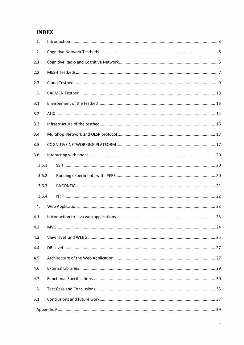
INDEX
1. Introduction .................................................................................................................................. 3
2. Cognitive Network Testbeds ........................................................................................................ 5
2.1 Cognitive Radio and Cognitive Network ....................................................................................... 5
2.2 MESH Testbeds ............................................................................................................................. 7
2.3 Cloud Testbeds ............................................................................................................................. 9
3. CARMEN Testbed ....................................................................................................................... 13
3.1 Environment of the testbed ....................................................................................................... 13
3.2 ALIX ............................................................................................................................................. 14
3.3 Infrastructure of the testbed ...................................................................................................... 16
3.4 Multihop Network and OLSR protocol ...................................................................................... 17
3.5 COGNITIVE NETWORKING PLATFORM ....................................................................................... 17
3.6 Interacting with nodes ............................................................................................................... 20
3.6.1 SSH ...................................................................................................................................... 20
3.6.2 Running experiments with IPERF ....................................................................................... 20
3.6.3 IWCONFIG ........................................................................................................................... 21
3.6.4 NTP ..................................................................................................................................... 22
4. Web Application ......................................................................................................................... 23
4.1 Introduction to Java web applications ....................................................................................... 23
4.2 MVC ............................................................................................................................................ 24
4.3 View level and WEBGL ............................................................................................................... 25
4.4 DB Level ...................................................................................................................................... 27
4.5 Architecture of the Web Application ......................................................................................... 27
4.6 External Libraries ........................................................................................................................ 29
4.7 Functional Specifications ............................................................................................................ 30
5. Test Case and Conclusions ......................................................................................................... 35
5.1 Conclusions and future work ...................................................................................................... 37
Appendix A ........................................................................................................................................... 39

2
References ........................................................................................................................................... 41
3
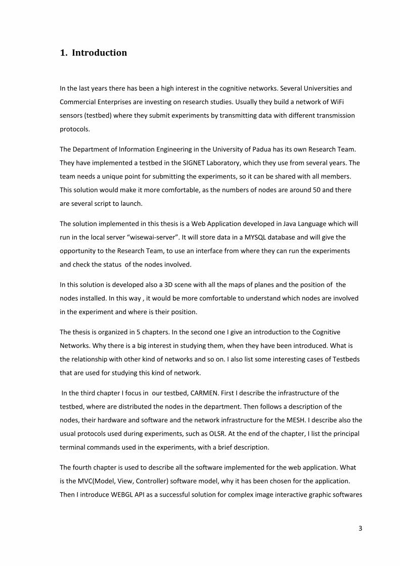
1. Introduction
In the last years there has been a high interest in the cognitive networks. Several Universities and
Commercial Enterprises are investing on research studies. Usually they build a network of WiFi
sensors (testbed) where they submit experiments by transmitting data with different transmission
protocols.
The Department of Information Engineering in the University of Padua has its own Research Team.
They have implemented a testbed in the SIGNET Laboratory, which they use from several years. The
team needs a unique point for submitting the experiments, so it can be shared with all members.
This solution would make it more comfortable, as the numbers of nodes are around 50 and there
are several script to launch.
The solution implemented in this thesis is a Web Application developed in Java Language which will
run in the local server “wisewai-server”. It will store data in a MYSQL database and will give the
opportunity to the Research Team, to use an interface from where they can run the experiments
and check the status of the nodes involved.
In this solution is developed also a 3D scene with all the maps of planes and the position of the
nodes installed. In this way , it would be more comfortable to understand which nodes are involved
in the experiment and where is their position.
The thesis is organized in 5 chapters. In the second one I give an introduction to the Cognitive
Networks. Why there is a big interest in studying them, when they have been introduced. What is
the relationship with other kind of networks and so on. I also list some interesting cases of Testbeds
that are used for studying this kind of network.
In the third chapter I focus in our testbed, CARMEN. First I describe the infrastructure of the
testbed, where are distributed the nodes in the department. Then follows a description of the
nodes, their hardware and software and the network infrastructure for the MESH. I describe also the
usual protocols used during experiments, such as OLSR. At the end of the chapter, I list the principal
terminal commands used in the experiments, with a brief description.
The fourth chapter is used to describe all the software implemented for the web application. What
is the MVC(Model, View, Controller) software model, why it has been chosen for the application.
Then I introduce WEBGL API as a successful solution for complex image interactive graphic softwares

4
It is wide spread and already integrated in all browsers. Then it is the turn of the framework X3DOM,
well accepted by developers for translating standard scripting language in WEBGL solution.
Then follows a quick listing of external java libraries, comfortable for implementing the core of the
application. The rest of the chapter is dedicated mostly to the functional part. How the end user
should interact with the application, and the description of each element of the web page. What are
the steps to take for submitting an experiment and the rules that validate the data inputted.
In the last chapter I describe a real experiment used for testing the application, followed by the
analyzes of the output data. At the end I define the conclusions of the work done.

5
2. Cognitive Network Testbeds
The technology used in the network of nowadays causes several limitations when is applied in a
dynamic scenario as it presents limitations in adapting to changes and interactions, often resulting
in sub-optimal performance. The network elements (such as nodes, protocols) are unable to make
intelligent decisions and adaptions. The rigidness of the layered protocol architecture doesn’t give
to the elements sufficient information about the conditions experience by other elements, so the
element is adapted to the network basing only in the proper information. The adaption is done in
consequence of the events and problems that occur in the network. This example and others more
aware the need of a different approach in designing the protocols of the network. One of the
several solutions studied in different researching works is the cognitive network which seems to
have the capacity of removing the above limitations by allowing networks to observe ,act, and learn
in order to optimize their performance.[1]
2.1 Cognitive Radio and Cognitive Network
The first researcher that studied the cognitive networks was Theo Kantor during his doctoral
research at the Royal Institute of technology in Stockholm, defining the cognitive network as the
network with memory in his publication in June 1998. At the same period, in the same institute , Joe
Mitola was studying the cognitive radio. In Mitola's thesis, published in August, 1999 was included
the following quote "Over time, the Radio Knowledge Representation Language -empowered
network can learn to distinguish a feature of the natural environment that does not match the
models. It could declare the errors to a cognitive network." This is the earliest publication of the
concept cognitive network, since Kantor published a bit later1.
Cognitive Radio(CR) is considered as a potential solution to improve spectrum utilization via
opportunistic spectrum implement. Using Software defined Radio(SDR) technology, a flexible radio
platform can potentially configure a Cognitive Engine(CE) to transmit many different incompatible
radio standards. As by the definition of Mitola, a CR “is a goal-driven framework in which the radio
autonomously observes the radio environment, infers context, assesses alternatives, generates
plans, supervises multimedia services, and learns from is mistakes.”[17]
1 http://en.wikipedia.org/wiki/Cognitive_network
6
We can think of the Cognitive network as a data communication network between intelligent nodes.
The nodes have sufficient information of the status of their device and also about the network they
are connected to. They can use this information to adapt theirselves to different conditions or
scenarios that may occur in the network and take the proper decisions. So the objective is to have a
proactive behavior of the network in order that it can predict different situations and can take
actions before they occur. The node could work in two modes, proactive and reactive. When the
cognitive proactive mode fails, it can switch in reactive mode. But the aim is to use the knowledge
gathered in past cases and use this information for predicting the behavior of the network. So the
mail goal is to avoid blocking issues and increase network efficiency and performance. Using this
approach is met also the goal of optimizing the communication for the whole network.
Network becomes cognitive when all its components are self-adjusting and self-aware. When the
decisions of configuring the network and the way nodes behave are taken from and external
component, then the network is no more Cognitive. Future aims are that the network itself takes
decisions and find optimal ways of connecting devices and setting network parameters to reach best
performance for data transfers. This can be achieved by using the Knowledge Base of past events
but also for events that are not happened, but are likely to happen. Preventing data loss and
congestion can be achieved by using routing algorithms and knowing the status of every node.[2]
Cognitive network is different from cognitive radio as it covers all the layers of the OSI model (not
only layers 1 and 2 as with CR).
As Cognitive Radio is only considering scope of single radio and tries to optimize conditions for
single user only, Cognitive network is trying to optimize whole network in order to achieve best
end-to-end performance as anticipated earlier. The Cognitive Radio can be involved in a Cognitive
Network to optimize their usage taking account also of the other nodes.
Software Defined Networks and software defined radios are both closely related Cognitive
Networks, while they don’t necessarily have any intelligent components. Cognitive networks and
Cognitive Radio networks depends on both of these technologies, because they enable network to
adapt dynamically without user intervention.
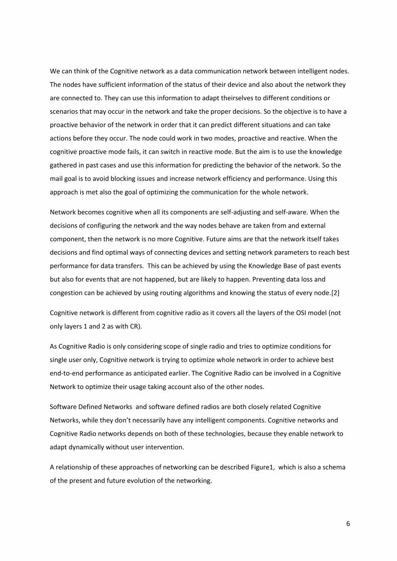
A relationship of these approaches of networking can be described Figure1, which is also a schema
of the present and future evolution of the networking.
7
Figure 1 Evolution of networks
The schema defines a natural evolution of the networks. As anticipated previously, once the
Cognitive Radios were introduced, a solution such as Cognitive networks was foreseen.
2.2 MESH Testbeds
In the last years there has been a high interest in the cognitive networks. Several Universities and
Commercial Enterprises are investing on research studies. Usually they build a network of wifi
sensors (testbed) where they submit experiments by transmitting data with different transmission
protocols.
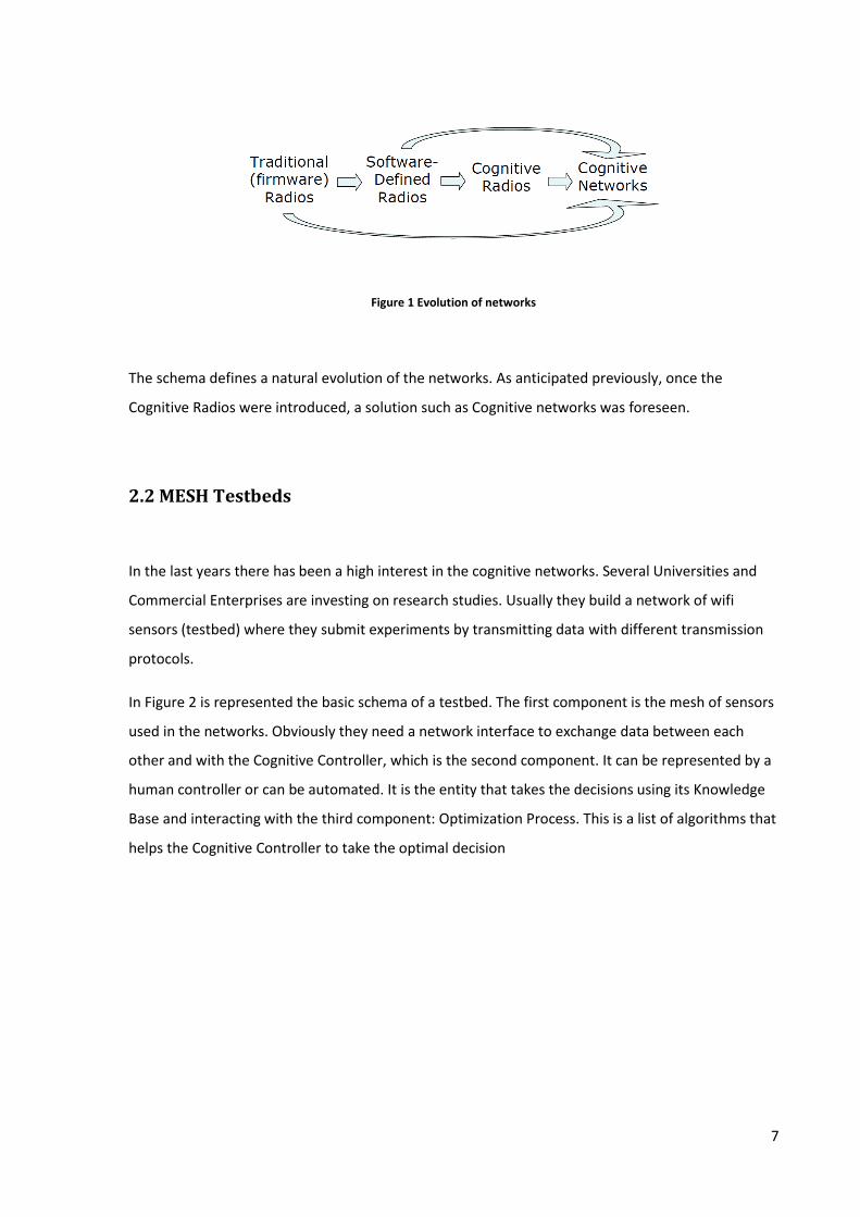
In Figure 2 is represented the basic schema of a testbed. The first component is the mesh of sensors
used in the networks. Obviously they need a network interface to exchange data between each
other and with the Cognitive Controller, which is the second component. It can be represented by a
human controller or can be automated. It is the entity that takes the decisions using its Knowledge
Base and interacting with the third component: Optimization Process. This is a list of algorithms that
helps the Cognitive Controller to take the optimal decision

8
Figure 2 Schema of a Cognitive Network testbed
Most of the testbeds are designed to test CR techniques, but they can be adapted to investigate CN
solutions. They are based on software defined radio (SDR), a radio communication system where all
the layers of the protocol stack are implemented in software on a device. The device is connected to
ad hoc hardware responsible for producing the modulated signal. The universal software radio
peripheral (USRP) is a common choice to build the physical layer; another option is to use the
wireless open access research platform (WARP, http://warp.rice.edu/). With the WARP board, both
the physical (PHY) and MAC layers can be implemented on the field programmable gate array
(FPGA) to reduce latency. However, the FPGA on the WARP board is not powerful enough to
accommodate full-duplex communication, which is often desirable in CR testbeds.[3]
Three interesting testbeds are the Virginia Tech cognitive radio network (VT-CoRNET) 2 , the open
access radio testbed for next-generation wireless networks (ORBIT) , and EMULAB , which are CR
testbeds with the goal of optimizing spectrum sharing. They are composed of a very flexible
architecture, can be controlled remotely, and are available to the research community to run
network experiments.
VT-CoRNET[18] is an SDR testbed developed using 48 USRP2 nodes, a newer version of USRP nodes.
The nodes are spread over four floors of a building and equipped with a custom made
daughterboard spanning a frequency range from 100 MHz to 4 GHz. The 48 wireless software-
defined nodes provide a hardware and software sandbox for software sandbox for SDR and CR
development. This sandbox is designed so that the testbed users will have complete access to a
high-performance computing platform so they will be able to develop next-generation wireless
techniaques.
2 http://cornet.wireless.vt.edu/
9
IRIS[19]: Implementing Radio in Software(IRIS) is a testbed project in Europe, at Trinity College
Dublin, Ireland. The main idea is the same as for VT-CoRNET: it is composed of a highly flexible
architecture for real-time radio reconfiguration. Its nodes are fully reconfigurable SDR (USRP2). IRIS
is designed to be component-based. Discrete signal processing functions such as digital filter or
modulator are implemented as components with generic interfaces for life-cycle control, data
passing, and reconfiguration.
ORBIT[20] is a heterogeneous testbed developed at WINLAB, Rutgers University. It uses a two-tier
architecture with a lab emulator trial network architecture to deal with the issue of reproducibility
in experimentation. The radio grid emulator consists of 64 wireless nodes. Users can have full access
to the radio nodes used in their experiments, download and run their own OS image and software
packages, control and reboot the nodes and other operations.
EstiNet[21]: is developed in EstiNet Technologies,Inc and uses an unique approach to testing the
functions and performances of OpenFlow controllers. By using particular simulation methodology,
called “kernel re-entering”, EstiNet combines the advantages of both simulation end emulation
approaches where each simulated host can run the real Linux operating system.
2.3 Cloud Testbeds
Fed4Fire3 is a project of the European Union, for federating the Mesh Network Tesbeds used in
different Universities or Researching Laboratories.
It uses some frameworks such as : OMF(Optimal Measurement and Management Framework )4 and
OML (Optimal Measurement Library)5
OMF is a generic framework for controlling and managing networking testbeds, co-developed by
NICTA6 and Winlab7.
OMF provides a domain-specific language, named OEDL, which allows the user to give an
Experiment description including information about the resources needed for the experiment and
their configuration, description about the applications to use in the experiment and data collected
3 http://doc.fed4fire.eu/index.html
4 http://omf.mytestbed.net/projects/omf/wiki/An_Introduction_to_OMF
5 http://oml.mytestbed.net/projects/oml/wiki/
6 http://nicta.com.au/
7 http://www.winlab.rutgers.edu/

10
to be analyzed, also a description of the different tasks to perform during the experiment and
scheduling time or events that trigger them.
OMF provides also a set of software tools that use as input the experiment described at the first
step and then configure the required nodes and resources involved in the experiment. After that the
Experiment is executed by sending the commands to the resources and in a successive step are
collected the measurement data from the applications or resources
Figure 3 OMF: process used in the testbed8
As mentioned, the input to OMF is an experiment described with OEDL. OMF deploys and configures
this experiment on the testbeds based on the user's description. It then initiates and controls the
execution of the experiment. While the experiment is being executed, data is measured and
collected according to the user's description. This data is stored in a database for later analysis, or
re-used by the OMF's control functions to steer some aspects of the experiment.
OML is an instrumentation tool that allows application writers to define customizable measurement
points (MP) inside new or pre-existing applications. Experimenters running the applications can then
direct the measurement streams (MS) from these MPs to remote collection points, for storage in
measurement databases
Experiments can be submitted in Fed4Fire with the proper account, previously registered, and by
using the software jFED9 that facilities user interaction with the testbed.
8 Courtesy of http://omf.mytestbed.net/
9 http://jfed.iminds.be

11
Some of the Researching Group that participate in this project are :
The Virtual Wall hosted at and operated by iMinds iLab.t. There are currently +300 physical servers
available ranging from 4 to 16 raw cores per server and interconnected by multiple gigabit
interfaces, some with 10 gigabit.Some of the nodes are connected to an OpenFlow switch to be able
to do OpenFlow experiments in a combination of servers, software OpenFlow switches and real
OpenFlow switches. The Virtual wall supports OMF as described here Control your experiment with
OMF and OML as described here Instrument your experiment with OML.
Planetlab Europe is the European arm of the global PlanetLab system, the world’s largest research
networking facility, which gives experimenters access to Internet-connected Linux virtual machines
on over 1000 networked servers located in the United States, Europe, Asia, and elsewhere.

12
13
3. CARMEN Testbed
The Department of Information Engineering in the University of Padua has its own Research Team.
They have implemented a testbed named CARMEN(Cognitive Android Mesh Network Testbed) in
the SIGNET Laboratory, which they use from several years for researching aims. In this chapter we
will describe step by step how it is implemented.
3.1 Environment of the testbed
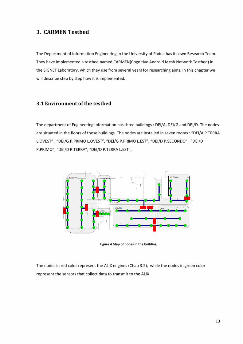
The department of Engineering Information has three buildings : DEI/A, DEI/G and DEI/D. The nodes
are situated in the floors of those buildings. The nodes are installed in seven rooms : “DEI/A P.TERRA
L.OVEST” , “DEI/G P.PRIMO L.OVEST”, “DEI/G P.PRIMO L.EST”, “DEI/D P.SECONDO”, “DEI/D
P.PRIMO”, “DEI/D P.TERRA”, “DEI/D P.TERRA L.EST”,
Figure 4 Map of nodes in the building
The nodes in red color represent the ALIX engines (Chap 3.2), while the nodes in green color
represent the sensors that collect data to transmit to the ALIX.

14
Figura 5 SIGNET laboratory
In Figure 5 is represented SIGNET laboratory, in which is installed a part of the MESH. In the areal
cables are installed the sensors, while in desk appended in the wall are positioned the ALIX nodes.
3.2 ALIX
ALIX engines are calculators but with limited functionalities. They are optimized for networking.
They have both Ethernet and Wifi card. The Operating System installed on the ALIX is Voyage Linux,
a derivation of Debian.
In figure 6 are listed the hardware characteristics of an ALIX 3d3. As we will deepen later, they only
have a Flash storage, and for this reason we will need to store the softwares and files for each node
in a shared server.
Figure 6 ALIX hardware specifications
15
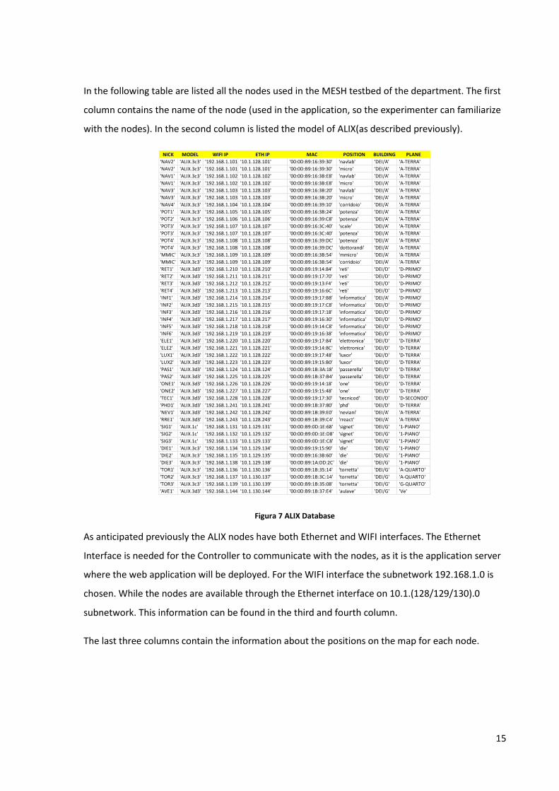
In the following table are listed all the nodes used in the MESH testbed of the department. The first
column contains the name of the node (used in the application, so the experimenter can familiarize
with the nodes). In the second column is listed the model of ALIX(as described previously).
Figura 7 ALIX Database
As anticipated previously the ALIX nodes have both Ethernet and WIFI interfaces. The Ethernet
Interface is needed for the Controller to communicate with the nodes, as it is the application server
where the web application will be deployed. For the WIFI interface the subnetwork 192.168.1.0 is
chosen. While the nodes are available through the Ethernet interface on 10.1.(128/129/130).0
subnetwork. This information can be found in the third and fourth column.
The last three columns contain the information about the positions on the map for each node.
NICK MODEL WIFI IP ETH IP MAC POSITION BUILDING PLANE
'NAV2' 'ALIX.3c3' '192.168.1.101' '10.1.128.101' '00:0D:B9:16:39:30' 'navlab' 'DEI/A' 'A-TERRA'
'NAV2' 'ALIX.3c3' '192.168.1.101' '10.1.128.101' '00:0D:B9:16:39:30' 'micro' 'DEI/A' 'A-TERRA'
'NAV1' 'ALIX.3c3' '192.168.1.102' '10.1.128.102' '00:0D:B9:16:3B:E8' 'navlab' 'DEI/A' 'A-TERRA'
'NAV1' 'ALIX.3c3' '192.168.1.102' '10.1.128.102' '00:0D:B9:16:3B:E8' 'micro' 'DEI/A' 'A-TERRA'
'NAV3' 'ALIX.3c3' '192.168.1.103' '10.1.128.103' '00:0D:B9:16:3B:20' 'navlab' 'DEI/A' 'A-TERRA'
'NAV3' 'ALIX.3c3' '192.168.1.103' '10.1.128.103' '00:0D:B9:16:3B:20' 'micro' 'DEI/A' 'A-TERRA'
'NAV4' 'ALIX.3c3' '192.168.1.104' '10.1.128.104' '00:0D:B9:16:39:10' 'corridoio' 'DEI/A' 'A-TERRA'
'POT1' 'ALIX.3c3' '192.168.1.105' '10.1.128.105' '00:0D:B9:16:3B:24' 'potenza' 'DEI/A' 'A-TERRA'
'POT2' 'ALIX.3c3' '192.168.1.106' '10.1.128.106' '00:0D:B9:16:39:C8' 'potenza' 'DEI/A' 'A-TERRA'
'POT3' 'ALIX.3c3' '192.168.1.107' '10.1.128.107' '00:0D:B9:16:3C:40' 'scale' 'DEI/A' 'A-TERRA'
'POT3' 'ALIX.3c3' '192.168.1.107' '10.1.128.107' '00:0D:B9:16:3C:40' 'potenza' 'DEI/A' 'A-TERRA'
'POT4' 'ALIX.3c3' '192.168.1.108' '10.1.128.108' '00:0D:B9:16:39:DC' 'potenza' 'DEI/A' 'A-TERRA'
'POT4' 'ALIX.3c3' '192.168.1.108' '10.1.128.108' '00:0D:B9:16:39:DC' 'dottorandi' 'DEI/A' 'A-TERRA'
'MMIC' 'ALIX.3c3' '192.168.1.109' '10.1.128.109' '00:0D:B9:16:3B:54' 'mmicro' 'DEI/A' 'A-TERRA'
'MMIC' 'ALIX.3c3' '192.168.1.109' '10.1.128.109' '00:0D:B9:16:3B:54' 'corridoio' 'DEI/A' 'A-TERRA'
'RET1' 'ALIX.3d3' '192.168.1.210' '10.1.128.210' '00:0D:B9:19:14:84' 'reti' 'DEI/D' 'D-PRIMO'
'RET2' 'ALIX.3d3' '192.168.1.211' '10.1.128.211' '00:0D:B9:19:17:70' 'reti' 'DEI/D' 'D-PRIMO'
'RET3' 'ALIX.3d3' '192.168.1.212' '10.1.128.212' '00:0D:B9:19:13:F4' 'reti' 'DEI/D' 'D-PRIMO'
'RET4' 'ALIX.3d3' '192.168.1.213' '10.1.128.213' '00:0D:B9:19:16:6C' 'reti' 'DEI/D' 'D-PRIMO'
'INF1' 'ALIX.3d3' '192.168.1.214' '10.1.128.214' '00:0D:B9:19:17:B8' 'informatica' 'DEI/A' 'D-PRIMO'
'INF2' 'ALIX.3d3' '192.168.1.215' '10.1.128.215' '00:0D:B9:19:17:C8' 'informatica' 'DEI/D' 'D-PRIMO'
'INF3' 'ALIX.3d3' '192.168.1.216' '10.1.128.216' '00:0D:B9:19:17:18' 'informatica' 'DEI/D' 'D-PRIMO'
'INF4' 'ALIX.3d3' '192.168.1.217' '10.1.128.217' '00:0D:B9:19:16:30' 'informatica' 'DEI/D' 'D-PRIMO'
'INF5' 'ALIX.3d3' '192.168.1.218' '10.1.128.218' '00:0D:B9:19:14:C8' 'informatica' 'DEI/D' 'D-PRIMO'
'INF6' 'ALIX.3d3' '192.168.1.219' '10.1.128.219' '00:0D:B9:19:16:38' 'informatica' 'DEI/D' 'D-PRIMO'
'ELE1' 'ALIX.3d3' '192.168.1.220' '10.1.128.220' '00:0D:B9:19:17:84' 'elettronica' 'DEI/D' 'D-TERRA'
'ELE2' 'ALIX.3d3' '192.168.1.221' '10.1.128.221' '00:0D:B9:19:14:8C' 'elettronica' 'DEI/D' 'D-TERRA'
'LUX1' 'ALIX.3d3' '192.168.1.222' '10.1.128.222' '00:0D:B9:19:17:48' 'luxor' 'DEI/D' 'D-TERRA'
'LUX2' 'ALIX.3d3' '192.168.1.223' '10.1.128.223' '00:0D:B9:19:15:B0' 'luxor' 'DEI/D' 'D-TERRA'
'PAS1' 'ALIX.3d3' '192.168.1.124' '10.1.128.124' '00:0D:B9:1B:3A:18' 'passerella' 'DEI/D' 'D-TERRA'
'PAS2' 'ALIX.3d3' '192.168.1.225' '10.1.128.225' '00:0D:B9:1B:37:B4' 'passerella' 'DEI/D' 'D-TERRA'
'ONE1' 'ALIX.3d3' '192.168.1.226' '10.1.128.226' '00:0D:B9:19:14:18' 'one' 'DEI/D' 'D-TERRA'
'ONE2' 'ALIX.3d3' '192.168.1.227' '10.1.128.227' '00:0D:B9:19:15:48' 'one' 'DEI/D' 'D-TERRA'
'TEC1' 'ALIX.3d3' '192.168.1.228' '10.1.128.228' '00:0D:B9:19:17:30' 'tecnicod' 'DEI/D' 'D-SECONDO'
'PHD1' 'ALIX.3d3' '192.168.1.241' '10.1.128.241' '00:0D:B9:1B:37:80' 'phd' 'DEI/D' 'D-TERRA'
'NEV1' 'ALIX.3d3' '192.168.1.242' '10.1.128.242' '00:0D:B9:1B:39:E0' 'neviani' 'DEI/A' 'A-TERRA'
'RRE1' 'ALIX.3d3' '192.168.1.243' '10.1.128.243' '00:0D:B9:1B:39:C4' 'rreact' 'DEI/A' 'A-TERRA'
'SIG1' 'ALIX.1c' '192.168.1.131' '10.1.129.131' '00:0D:B9:0D:1E:68' 'signet' 'DEI/G' '1-PIANO'
'SIG2' 'ALIX.1c' '192.168.1.132' '10.1.129.132' '00:0D:B9:0D:1E:D8' 'signet' 'DEI/G' '1-PIANO'
'SIG3' 'ALIX.1c' '192.168.1.133' '10.1.129.133' '00:0D:B9:0D:1E:C8' 'signet' 'DEI/G' '1-PIANO'
'DIE1' 'ALIX.3c3' '192.168.1.134' '10.1.129.134' '00:0D:B9:19:15:90' 'die' 'DEI/G' '1-PIANO'
'DIE2' 'ALIX.3c3' '192.168.1.135' '10.1.129.135' '00:0D:B9:16:3B:60' 'die' 'DEI/G' '1-PIANO'
'DIE3' 'ALIX.3c3' '192.168.1.138' '10.1.129.138' '00:0D:B9:1A:DD:2C' 'die' 'DEI/G' '1-PIANO'
'TOR1' 'ALIX.3c3' '192.168.1.136' '10.1.130.136' '00:0D:B9:1B:35:14' 'torretta' 'DEI/G' 'A-QUARTO'
'TOR2' 'ALIX.3c3' '192.168.1.137' '10.1.130.137' '00:0D:B9:1B:3C:14' 'torretta' 'DEI/G' 'A-QUARTO'
'TOR3' 'ALIX.3c3' '192.168.1.139' '10.1.130.139' '00:0D:B9:1B:35:08' 'torretta' 'DEI/G' 'G-QUARTO'
'AVE1' 'ALIX.3d3' '192.168.1.144' '10.1.130.144' '00:0D:B9:1B:37:E4' 'aulave' 'DEI/G' 'Ve'
16
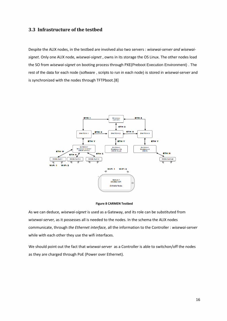
3.3 Infrastructure of the testbed
Despite the ALIX nodes, in the testbed are involved also two servers : wisewai-server and wisewai-
signet. Only one ALIX node, wisewai-signet , owns in its storage the OS Linux. The other nodes load
the SO from wisewai-signet on booting process through PXE(Preboot Execution Environment) . The
rest of the data for each node (software , scripts to run in each node) is stored in wisewai-server and
is synchronized with the nodes through TFTPboot.[8]
Figure 8 CARMEN Testbed
As we can deduce, wisewai-signet is used as a Gateway, and its role can be substituted from
wisewai-server, as it possesses all is needed to the nodes. In the schema the ALIX nodes
communicate, through the Ethernet interface, all the information to the Controller : wisewai-server
while with each other they use the wifi interfaces.
We should point out the fact that wisewai-server as a Controller is able to switchon/off the nodes
as they are charged through PoE (Power over Ethernet).

17
3.4 Multihop Network and OLSR protocol
The testbed is projected to make experiments over a MESH network using multihop protocols such
OLSR (Optimized Link State Routing Protocol).
OLSR is a proactive protocol, i.e it exchanges information continuously over all the networks and
stores the routes in the routing tables, having so the necessary information when data will be
transmitted to a node. It is an optimization of the protocol Link State : the central concept of the
protocol are the use of Multipoint Relays(MPR), the nodes elected for forwarding packets through
flooding process. Using the MPR nodes we reduce the overhead that could be caused in a classic
flooding where each node retransmits every packet. The MPR node is responsible for
communicating to the network the route toward the nodes from which it has been elected. So it
transmits less information than in Link State but sufficient to define the Optimal routes in the
network.
The protocol is efficient in wide and dense networks and it is also applicable to networks with
dynamic topology over time. It doesn’t need to use a reliable communication for the control packets
as they are sent periodically, and is accepted the fact of data loss as usually done in frequent
networks. OLSR doesn’t need an ordering process of the packets received as each transmitted
packets is furnished of a sequence number in order that the receiver is able to identify recent
received packets. So as one can deduce, the packets are send over UDP protocol and no changes is
needed to be done on IP packets.
OLSR performs hop by hop routing. MPRs are made in a way that covers all nodes two hop away.
3.5 COGNITIVE NETWORKING PLATFORM
In this section is described the Testbed developed by the Researcher Team. It is composed by static
nodes (ALIX) and mobile nodes (Nexus 7 tablets). The experiments are controlled and analyzed by a
software (COGNET) developed by the same Researcher Team10.
10
The description of this section is done thanks to the paper of the researcher Matteo Danieletto [3]

18
COGNITIVE NETWORKING PLATFORM [3]
The software developed to create a mobile ad hoc network is composed of three parts: Cognet-
Module, CognetNode, and CognetManager, as illustrated in the following figure.
Figure 9 Schema of CARMEN testbed
It has been tested in a heterogeneous network composed of 4 Android devices and 50 fixed devices
with different Alix versions. CognetModule can observe and modify the values of the TCP
parameters by reading and modifying the struct tcp_sock C structure. This data structure contains all
the information about the TCP connections, and is refreshed every time a new TCP acknowledge
packet is received by the node. CognetModule uses static struct tcp_congestion_ops, a kernel C
structure to retrieve the struct tcp_sock and modify, on the fly, some TCP parameters. In particular,
the congestion avoidance algorithm is implemented in CognetModule by creating several proc files,
stored in /proc/CARMEN, to exchange information between the kernel and user space. Thanks to
the proc files it is possible to change, on the fly, the TCP parameters. Furthermore, Cognet- Module
can also receive as inputs the IP netmask to select the TCP connections that should be monitored.
CognetNode is a user space program, which runs in a node to retrieve and change some MAC/TCP
parameters, and is connected to the other nodes in the network. CognetNode is composed of three
independent threads: TCP observation/ modification (O/M), MAC O/M, and ServerManager. The
TCP O/M thread is connected to the CognetModule via an interprocess communication channel
(Netlink socket). The thread exploits the blocking behavior of the C function read; thus, it reads the
Netlink buffer only when CognetModule is changing such a buffer. The TCP O/M thread can modify
in real time some TCP parameters like the TCP congestion window (CWND), retransmission time out
19
(RTO), and maximum allowed value of the CWND (CWND CLAMP) by exploiting the proc files
created by CognetModule.
The MAC O/M thread can observe/modify MAC parameters through the NL80211 socket
functionality (in the Linux kernel), which communicates directly with the driver.1 It saves the MAC
parameters of all the CognetNodes under its Wi-Fi coverage. CognetManager can remotely control
the nodes by sending commands to the ServerManager thread, such as start/stop the experiment,
change transmission channel or power, and change the sampling rate of the observed MAC
parameters. Two versions of CognetManager (with library in C) were developed, one for desktop
PCs and one for Android. It creates a C socket to open a TCP connection for each node in the
experiment to control the node. In our testbed, these commands are received via a wired
connection (for the Alix nodes) or via a second Wi-Fi interface (for the Android nodes). This second
control connection also avoids delays in the control of each node in case of critical events when the
main connection may be flooded with data traffic.
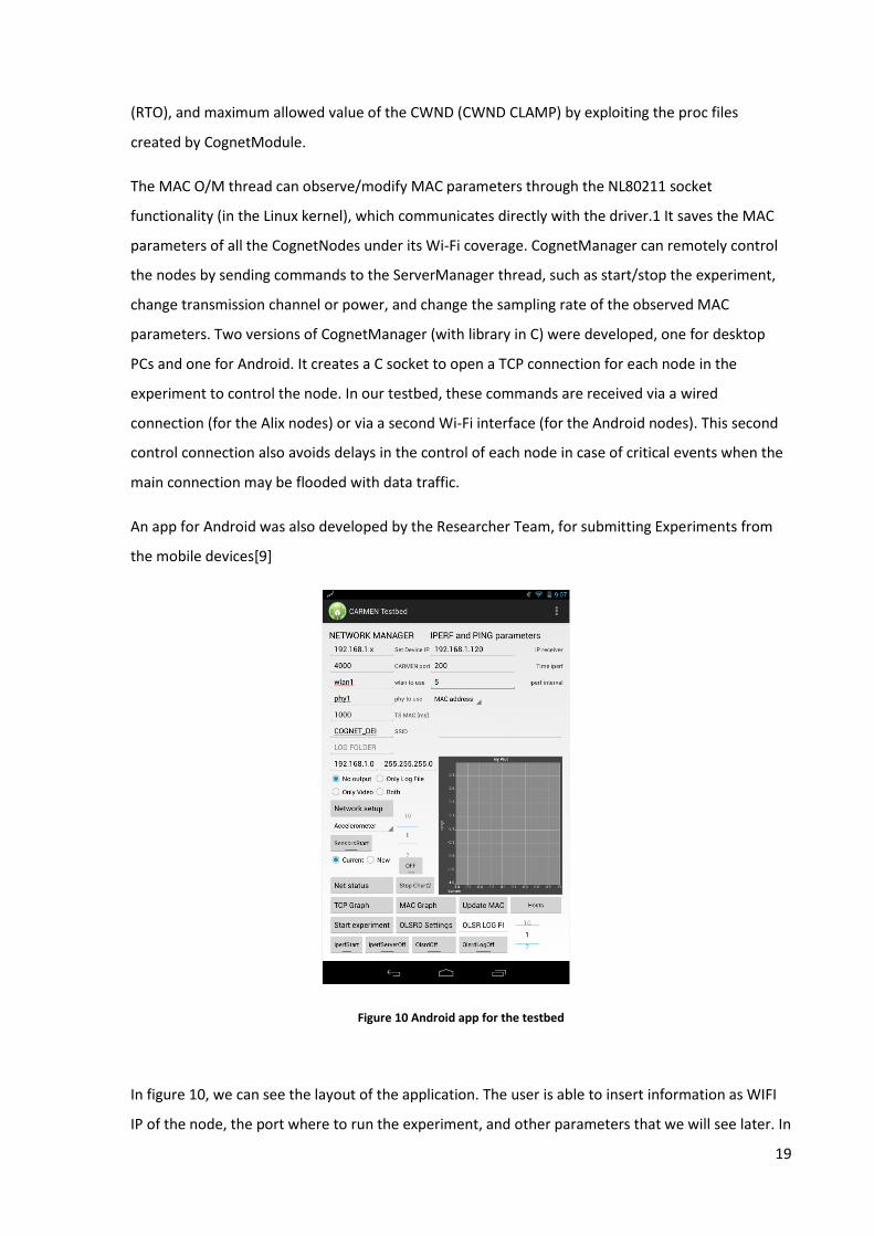
An app for Android was also developed by the Researcher Team, for submitting Experiments from
the mobile devices[9]
Figure 10 Android app for the testbed
In figure 10, we can see the layout of the application. The user is able to insert information as WIFI
IP of the node, the port where to run the experiment, and other parameters that we will see later. In
20
the application are implemented also functionalities that manage OLSR protocol settings for the
node.
3.6 Interacting with nodes
During the experiments we will need to set some parameters to the nodes and ask to execute
several actions. For this we will send terminal commands over SSH protocol.
3.6.1 SSH
Secure Shell (SSH)[12] is a cryptographic network protocol for secure data communication. This
protocol can be used for logging remotely through command line, or we can use it to execute other
commands or scripts. The two computers (server and client) need to be connected in the network,
and SSH will send information over a secure channel.
In our case SSH is needed to the Controller of the testbed to send commands to the nodes. All
commands will be encapsulated with SSH.
The usual command is : ssh user@server ……(command)
When we run it in terminal, the server asks the password of the user, and it is inputted in encrypted
mode.
3.6.2 Running experiments with IPERF
Iperf[11] is a software used to test the network. It can creates TCP and UDP packet streams and then
measure performance parameters such as the Throughput in the network that is running. It is
written in C language. To start the measuring process, IPERF needs to run in both client and servers
side by using the proper commands. It ca measure the throughput in between in both directions. It
is open-source software and is a cross-platform software, i.e it runs in Windows, Unix, Linx, etc.
During the measuring process it writes in output the amount of data followed by the throughput
measures. On server side it shows the IP of the client and the server connected and by default
expects to run in 10 sec.

21
Iperf can be used for comparison of both wired and wireless networking interfaces
To put the server in listening mode, is used the command: iperf –s
To transmit data from the client to the server is used the command: iperf –c [ip server]
On our experiments we will use the command parameterized as follows:
iperf –c [ip server] –t [dutation in sec of the transmission process]
iperf –c [ip server] –n [nr of bytes to send to the server]
3.6.3 IWCONFIG
Iwconfig[10] is a terminal command used to display or to change the parameters of the wireless
network interfaces of the host such as interface name, channel to communicate, transmission
power used when sending data. It can be used also to show wireless statistics as load of data
transmitted or received.
Some of the parameters it admits are:
channel: Sets the operating frequency or channel in the device. Channels are usually numbered
starting at 1 and at maximum 13 (total nr of WIFI protocol), and we may use iwlist to get the
total number of channels, list the available frequencies, and display the current frequency as a
channel.
Example: “iwconfig eth0 channel 3”
As nodes will communicate with each other through Wifi, we will need to change the channel of
their Wifi interface by choosing one of the thirteen channels of the protocol.
Txpower: For cards supporting multiple transmit powers, sets the transmit power in dBm. Other
features that can be used are: on and off enable and disable the radio, and auto and fixed enable
and disable power control (if those features are available).
Examples : “iwconfig eth0 txpower 15”
During the experiments will be changed the channel and the power of the nodes.

22
3.6.4 NTP
Network Time Protocol (NTP) [13] is a networking protocol for clock synchronization between
computer systems. NTP was originally designed by David L. Mills of the University of Delaware. It is a
client-server protocol where the server listens on UDP port 123. The protocol measures the latency
times during packets transmission over the network. It uses the UTC time and is independent of the
location. Actually it can synchronize the clocks of computers in internet with an error margin of 10
ms and 200 µs over a LAN.
In the departmental Testbed was decided to create a NTP server on a computer in the local network
that is available from all ALIX nodes. The nodes do not have direct access on the internet so they use
this server to synchronize their clocks.
As the nodes run a Linux OS, the synchronization could be performed through the daemon “ntpd”
implemented in the operating system, with the associated configuration file in the path
/etc/ntpd.conf. Ntpd can be used as client and server too. It is able to estimate and correct the
errors of the local clock, avoiding time error of the system when it is not connected to internet.
However for the Alix nodes will not use this direct approach as their OS is recharged continuously by
the controller “wisewai-server” and the clock is reset to year 2006. Synchronizing from such distant
time creates overloading problems to the OS. So it was thought to use a script that modifies
periodically the internal file of the OS to load by updating the clock. In this case the clocks of the
nodes will have a delay of quarter hour comparing to real time, and when the synchronization will
be performed it will not cause big issues.
23
4. Web Application
The name of the application is “webTestbed”. It will run in the WISEWAI-SERVER. The application
has been developed with Eclipse tool using JEE platform and JDK 1.7 but with compliance to version
1.6., as the version of JRE running in WISEWAI-SERVER is 1.6
4.1 Introduction to Java web applications
JavaServer Pages (JSP)[14] are used to integrate java coding with HTML, XML (or other document
types) in order to create dynamic web pages. As it contains java code the files needs to be compiled
on server side. The compiled pages will then be executed in the JVM (Java Virtual Machine) that will
deliver the information to the web server and finally to the user.
Java servlet is a Java class in Java EE that extend some capabilities of the application server. Quite
always they are used to elaborate information over HTTP protocol. For this when we create a servlet
on recent developer platforms ( such as Eclipse) , it inherits by default the two methods of the
HTTPServlet interface : doGet and doPost. So they are used to implement web applications. We can
use them in both interaction. When we ask information to the server the doGet method is invoked,
else when we want to print a response in our web page, we can invoke the doPost method by
writing HTML or XML code.
To deploy and run a servlet, a web container must be used.
Web container[15] (also known as a Servlet container) is that part of the web server or application
server ( if the web server is integrated in it) that manages the java servlets, their lifecycle and the
logic they have inside. Web container is also responsible to map the URLs to the proper servlet, to
redirect the output of a servlet to the proper web page by exchanging also information stored on
that page. A web container can also create servlet instances using the JSP files or other files that
include server-side code. . A web container implements also the web component platform of the
Java EE architecture, specifying a runtime environment for web components that includes security,
concurrency, lifecycle management, transaction, deployment, and other services
24
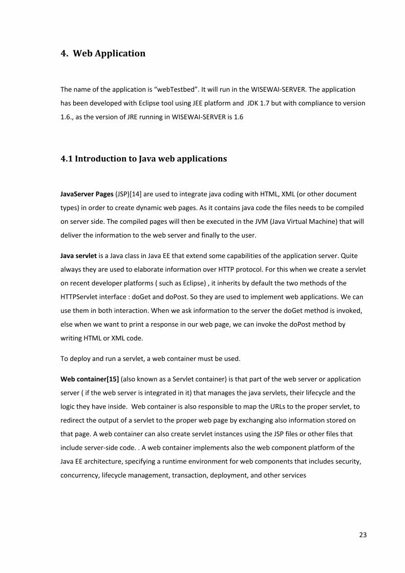
Figure 11 Servlet Container11
So to summarize, the user makes a request to JSP page. If the data are static, they are sent directly
to the runtime and are forwarded to the response. If not, the web container translates it in servlet,
compiles and then sends it to the runtime.
Most of the time, there is call to a specific servlet inside the JSP file. How does the Container know
which Servlet to compile when the JSP makes the request? In J2EE platform is used a web.xml file
that contains all the references to the servlets, and it is used by the container to take the roper
Servlet. In Appendix A, is posted the web.xml of the “webTestbed” application.
The web container used in WISEWAI-SERVER is Apache Tomcat v 6.024, an open source product
developed by Apache Software Foundation(AFS).
4.2 MVC
The application is implemented based in the MVC model.
The Model-View-Controller (MVC) [4] pattern separates the modeling of the domain, the
presentation, and the actions based on user input into three separate classes.
11
Courtesy of http://en.wikipedia.org/
25
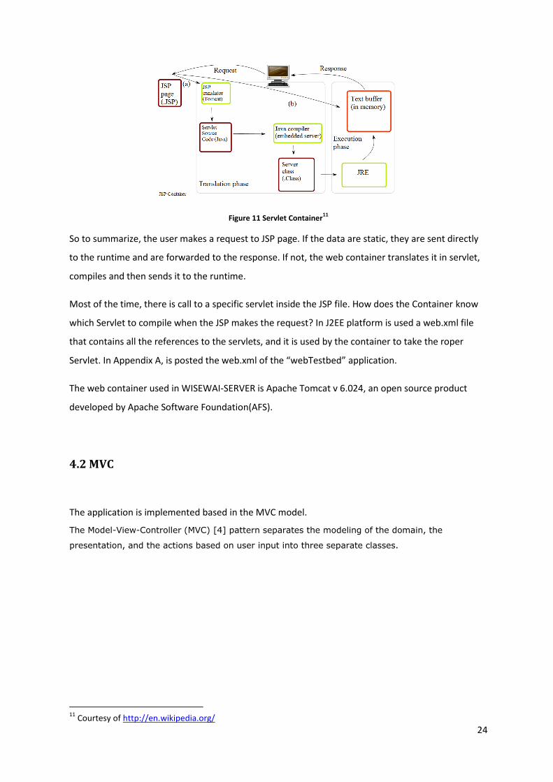
Figure 12 MVC model12
Model: The model is that part of the web application responsible to interact with the database,
the web services etc. It manages the behavior and data of the application domain and responds to
instructions to change state (usually from the controller).
View: The view manages the display of information on web pages, reports, templates that is
coming from the controller.
Controller: The controller is responsible for interpreting the actions of the user and translating
them in request to the model. It is also responsible for forwarding the output of the Model to the
View layer.
There is a direct dependency of the View and Controller layer to the Model layer that can be built
and tested independently of the other two layers. This give the possibility to the developers to
reuse the logic implemented in different cases as in a modular approach.
The MVC approach is wide spread and well admitted in all web applications.
4.3 View level and WEBGL
For the View Level have been used the standard languages : HTML and Javascript and also AJAX as
was required to make asynchronous calls to the servlets.
AJAX: (asynchronous JavaScript and XML) is a technique of integrating Javascipt language and XML
annotations used on the client-side to create asynchronous Web applications. Using Ajax, Web
12
Courtesy of http://code.tutsplus.com/tutorials/
26
applications can post data and request data from a server asynchronously (in the background)
without refreshing or influencing the behavior of the web page . Despite the name, the use of XML is
not mandatory (JSON is often used in the AJAJ variant), and the requests do not need to be
asynchronous. JQYERY has implemented libraries for AJAX.
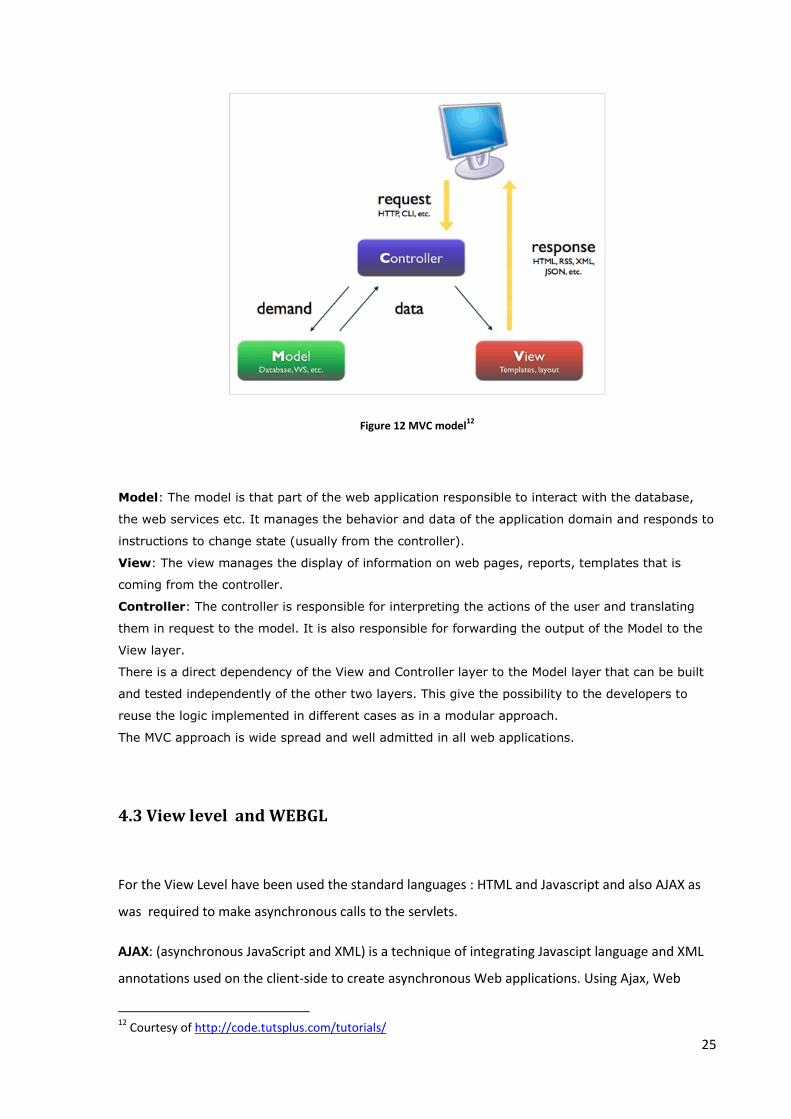
The implementation of the layout of the maps has been done using the WEBGL API through the
framework X3DOM. It has been developed based on the existing solution of CORNET[7] web
application adding further features. In the figure 13 is showed an effect of this technology.
WebGL[16] (Web Graphics Library) is a JavaScript API for rendering interactive 3D graphics and 2D
graphics within any compatible web browser without the use of plug-ins . This technology is
integrated with the most used browsers such as: Chrome, Mozilla, IE, Opera, allowing GPU
accelerated usage of physics and image processing and effects as part of the web page canvas.
WebGL elements can be integrated with HTML and so JSP pages for exchanging information with the
web application.
X3D13 is a standard file format and run-time architecture to represent and communicate 3D scenes
and objects using XML. It provides real time graphics content embedded in applications. X3D
describes 3D scenes in a similar way as HTML describes multimedia documents. X3D offers a higher
level of abstraction than WebGL code, which simplifies development. To integrate X3D format file
into web pages, is used X3DOM, a framework for manipulating (X)3D scenes as HTML5 DOM
elements that are rendered via WebGL. The system allows defining 3D scene description and
runtime behavior declaratively, without any low-level JavaScript coding.
13
http://www.web3d.org/x3d/what-x3d
Figure 13 3D effect with WEBGL

27
4.4 DB Level
The application use MYSQL RDBMS(relational database system) for storing the data. It is a free
product produced before from SUN MicroSystems and now owned by Oracle.
Figure 14 JDBC14
The application uses the JDBC driver (Java library) to resolve the MYSQL connector ( an external
library to be integrated into the project). The connector makes possible the communication with the
database. The queries are recognized as they are written in standard SQL language.
4.5 Architecture of the Web Application
In figure 15 is described the whole design of the web application. It is divided by three levels of the
MVC model and the database layer. We will describe it using the top-down approach.
14
Courtesy of http://theopentutorials.com/

28
Figure 15 Architecture of the application
The user interacts with the View level as described previously. The main form to submit an
Experiment is in the class Buildplane.jsp . We need to submit some information that are in the
variable “nodeEParsed”. This variable has been populated previously by calling the javabean
Node.java and its methods. The class JavaBean get the information connecting directly with the
database. As the information are modelled as a hashmap ( key , array<value>) , the comfortable
way to pass it to a Javascript variable is through JSON annotation. It just stores it in a String variable,
and then we parse it in Javascript variable, ready to use in jsp class.

29
When we submit; we call an AJAX function in the file “submit.js” . We use AJAX as we need to make
an asynchronous call to the server without refreshing the page. In this case we will call the servlet
“ExpermentS”. Tomcat container will be able to identify it through the web.xml file[Appendix A].
The servlet on its turn calls the javabean “IperfJsch”. It will pass the data we need to this class,
getting them from the Http request. Then all the business logic is handled in the class “IperfJsch” as
it should be. This class has a method that makes some SSH command to the nodes and the output
of the information will be passed to the servlet. The Tomcat container will then be able to print the
output in our JSP class.
A similar explanation can be done for the other functionalities. The steps are alike but sing other
servlets and other javabeans.
Properties files
In the application are stored two properties files : “config.properties” and “db.properties”.
The “config.properties” file contains the credentials of the root user that will run ssh commands on
the nodes.
The “db.properties” file contains the credentials for accessing the database.
Modifying these two properties files we will be able to run the application in different
environments.
4.6 External Libraries
When a developer wants to implement some functionalities that are common or he needs to use
standard technologies, could happen that the communities of developers have already produced a
library to use by avoiding writing a lot of code. These libraries need just to be imported in the
project and we jneed to know which are the methods we have to use.
The following libraries have been imported in the application as they offer a big help to avoid writing
further code.

30
OLSRINFO [5]: is a Java library that provides Java classes for parsing the data from jsoninfo plugin,
responsible for delivering all the information about the runtime status and configuration of OLSRD.
It is based on the Jackson JSON processing library. The code can be downloaded from the internet
and it can be manipulated by the developer to be integrated in web applications.
JSCH: is a Java implementation of SSH2.[6] . JSch allows connecting to an sshd server and can be
used for many operations such file transfer, executing scripts, etc. We can integrate its functionality
into our own Java programs. Main object that we need to declare are the Session we set with the
host and the Channel to be used for running the commands.
Gson: is a Java library that can be used to convert Java Objects into their JSON representation. It
can also do the inverse operations to convert a JSON string to an equivalent Java object like
Hashmaps. Gson is an open-source project hosted at http://code.google.com/p/google-gson.
4.7 Functional Specifications
In figure 16 we find the main page of the web application. It is composed of two JSP file. At the left
is positioned the “Buildplane.jsp” and at the right “planimetry.jsp”.
Figure 16 Main page of webTestbed
31
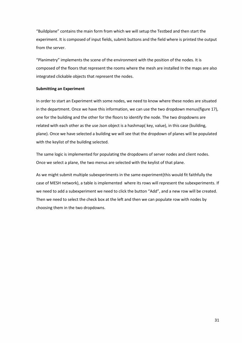
“Buildplane” contains the main form from which we will setup the Testbed and then start the
experiment. It is composed of input fields, submit buttons and the field where is printed the output
from the server.
“Planimetry” implements the scene of the environment with the position of the nodes. It is
composed of the floors that represent the rooms where the mesh are installed In the maps are also
integrated clickable objects that represent the nodes.
Submitting an Experiment
In order to start an Experiment with some nodes, we need to know where these nodes are situated
in the department. Once we have this information, we can use the two dropdown menus(figure 17),
one for the building and the other for the floors to identify the node. The two dropdowns are
related with each other as the use Json object is a hashmap( key, value), in this case (building,
plane). Once we have selected a building we will see that the dropdown of planes will be populated
with the keylist of the building selected.
The same logic is implemented for populating the dropdowns of server nodes and client nodes.
Once we select a plane, the two menus are selected with the keylist of that plane.
As we might submit multiple subexperiments in the same experiment(this would fit faithfully the
case of MESH network), a table is implemented where its rows will represent the subexperiments. If
we need to add a subexperiment we need to click the button “Add”, and a new row will be created.
Then we need to select the check box at the left and then we can populate row with nodes by
choosing them in the two dropdowns.

32
Figure 17 Experiment Form
For the setup of the testbed and starting an experiment we need to select first the server node and
then at least one client node.
To setup the testbed we need to click on the button “Setup” . It will run in background a ssh
command which triggers a shell script in all the nodes involved;
/root/COGNET_TESTBED/startCOGNET.sh
Then it will create a file in the server node file will all the Ethernet ip of the clients:
echo " + hostC + " >> /root/MANAGER/IP_FILES_WEBAPP/FILE_CLIENT_IP.TXT
and the testbed is ready to run the experiments.
Before starting the experiment we can set up the parameters, to use in the IPERF command. We can
choose the number of recurrent experiments in the “Repeat” field , and if we want to transmit data
in time mode or payload mode (MByte) we need to choose in the “select field”. By default the time
is set to 10 sec.
To start the experiment we need to click on the button “Start Experiment” . Fisrt it will reserve the
node server by triggering through ssh the command :
iperf –s

33
Then it will start sending data from the client nodes, in the mode we set previously:
if (isTime == true)
commandC = "iperf -c " + hostS + " -t " + time;
else if(isLoad == true)
commandC = "iperf -c " + hostS + " -n " + load;
else
commandC = "iperf -c " + hostS;
Once the client nodes have finished to transmit to the server, in the field “Status of Experiment” will
be printed if the experiment terminated successfully or not.
While the experiment is running, we can stop it by clicking in the button “Stop Experiment”. It will
send a kill command over ssh to the nodes selected as servers.
Synchronize Clocks: this functionality will synchronize the clocks of all nodes involved in the
experiment by using the NTP protocol and will print the result in the field “Status of
Synchronization”
Figure 18 Config nodes
Configuration of WIFI interface: this functionality will configure the wifi interface “wlan0” of all
nodes involved . We can select the transmission power when the nodes will transmit data and also
one of the thirteen channels of the wifi protocol.

34
Data Validation
In the application are implemented some rules for validating the data inputted.
One node cannot be selected as client if it has been selected as Server in the same sub-
experiment. When we try to do it, a popup window will alert us for the wrong action
The node Server should be always selected before the node client. If not a popup window
will alert us to avoid the action

35
5. Test Case and Conclusions
The aim is to setup correctly the testbed and run a simple experiment.
The nodes involved in the test will be DIE1(10.1.129.134) and DIE2(10.1.129.135). Node DIE1 is
chosen as the node server while DIE2 as the node client
At the beginning we need to insert the nodes in the table as described in 4.7. Then we need to click
the button “Setup testbed”.
Submitting the “Setup” button we can observe at the left of the figure that the output message is
“Setup finished successfully”. To verify the correctness, we need to check if the file has been
created by the ssh command :
echo " + hostC + " >>/root/MANAGER/IP_FILES_WEBAPP/FILE_CLIENT_IP.TXT
At the right of the figure we can observe that checking from a terminal, the script shell
“startCognet.sh” has been executed in both nodes and in the node server DIE1 has been generated
Figure 19 Setup of the Testbed
36
the file “FILE_CLIENT_IP.TXT” which contains the Ethernet IP of the clients involved in the testbed
and the localhost IP : 127.0.0.1
So this verifies that the testbed has been set up correctly. Now we can start our experiment.
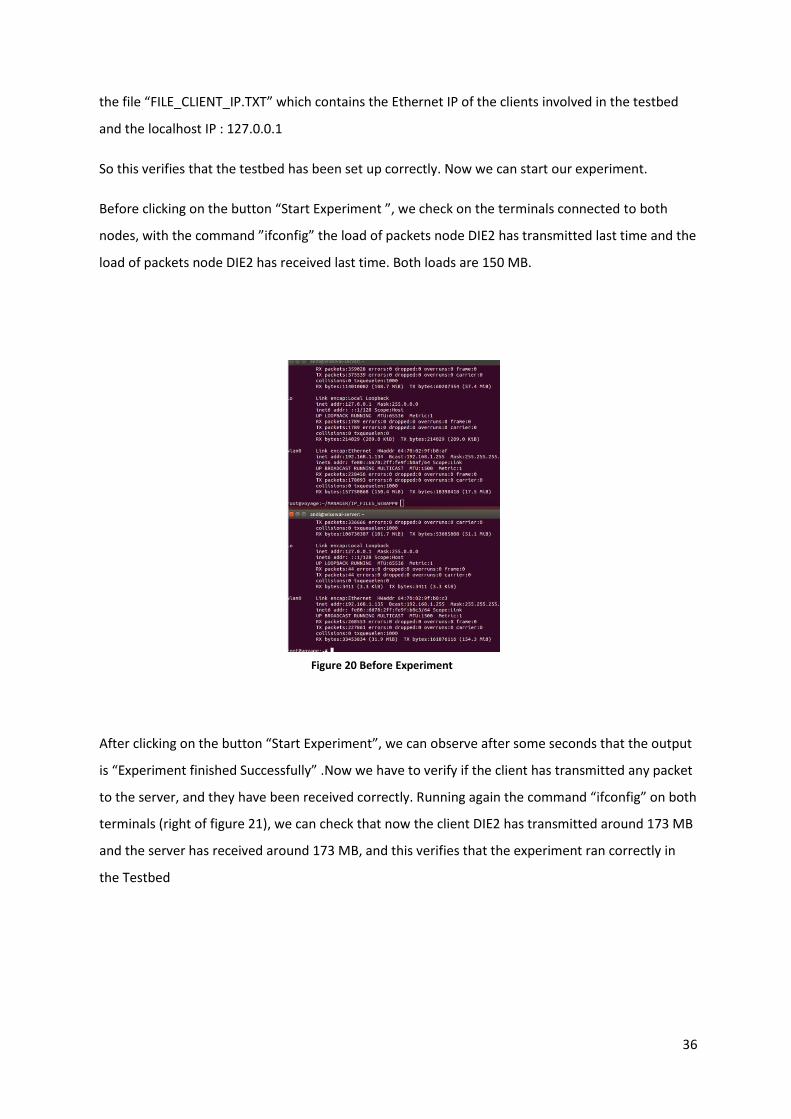
Before clicking on the button “Start Experiment ”, we check on the terminals connected to both
nodes, with the command ”ifconfig” the load of packets node DIE2 has transmitted last time and the
load of packets node DIE2 has received last time. Both loads are 150 MB.
After clicking on the button “Start Experiment”, we can observe after some seconds that the output
is “Experiment finished Successfully” .Now we have to verify if the client has transmitted any packet
to the server, and they have been received correctly. Running again the command “ifconfig” on both
terminals (right of figure 21), we can check that now the client DIE2 has transmitted around 173 MB
and the server has received around 173 MB, and this verifies that the experiment ran correctly in
the Testbed
Figure 20 Before Experiment

37
Figure 21 After Experiment
5.1 Conclusions and future work
At the beginning of the work, were defined the requirements with the Research Team for
implementing a Web Application in order to give support at the team during the Experiment they
submit on the Cognitive Network Testbed of the Department. The aim was to create an interactive
application that could make more comfortable possible the executing of the experiments.
The decision to implement the application with the Java language was determined by the fact that
the application should run in the “wisewai-server” that represents also the Controller of the
Testbed.
In this server is installed the Tomcat application server and JRE(java runtime environment) version 6.
So I used the same specification also in my Development Environment.

38
Another important requirement was to implement an interactive 3D object that could contain the
maps of the rooms and nodes of the Mesh network. In this way the user would be able to identify
the position of the nodes that are involved in the experiment and could extract useful information
about that node.
For this functionality was chosen to use a well-known technology such WEBGL. This decision was
taken because WEBGL is easy to integrate with web applications and it can run in all browsers.
The web application “webTestbed” was deployed successfully and its functionalities were tested by
the team. The results are the same as the ones expected.
There are several functionalities that can be implemented in the next months. One of these would
be to improve the interactivity of the 3D maps of the testbed and to add also functionalities to the
nodes integrated in the maps.
Another functionality useful would be to integrate the web application with JPERF, a graphical
solution of IPerf that gives the possibilities to analyze the data.

39
Appendix A
This is the code of the web.xml file. In this file are listed all the Servlets used in the application, with
their path and the other information useful to Tomcat when they will invoked.
<?xml version="1.0" encoding="UTF-8"?>
<web-app xmlns:xsi="http://www.w3.org/2001/XMLSchema-instance" xmlns="http://java.sun.com/xml/ns/javaee" xsi:schemaLocation="http://java.sun.com/xml/ns/javaee http://java.sun.com/xml/ns/javaee/web-app_2_5.xsd" id="WebApp_ID" version="2.5">
<display-name>webTestbed</display-name>
<welcome-file-list>
<welcome-file>index.html</welcome-file>
<welcome-file>index.htm</welcome-file>
<welcome-file>index.jsp</welcome-file>
<welcome-file>default.html</welcome-file>
<welcome-file>default.htm</welcome-file>
<welcome-file>default.jsp</welcome-file>
</welcome-file-list>
<servlet>
<servlet-name>ExperimentS</servlet-name>
<servlet-class>com.servlets.pkg.ExperimentS</servlet-class>
</servlet>
<servlet-mapping>
<servlet-name>ExperimentS</servlet-name>
<url-pattern>/ExperimentS</url-pattern>
</servlet-mapping>
<servlet>
<servlet-name>WconfigS</servlet-name>
<servlet-class>com.servlets.pkg.WconfigS</servlet-class>
</servlet>
<servlet-mapping>
<servlet-name>WconfigS</servlet-name>
<url-pattern>/WconfigS</url-pattern>
</servlet-mapping>
<servlet>
<servlet-name>ClockconfigS</servlet-name>
<servlet-class>com.servlets.pkg.ClockconfigS</servlet-class>
</servlet>
<servlet-mapping>
<servlet-name>ClockconfigS</servlet-name>
<url-pattern>/ClockconfigS</url-pattern>
</servlet-mapping>
<servlet>
<servlet-name>PingNodeS</servlet-name>
<servlet-class>com.servlets.pkg.PingNodeS</servlet-class>
</servlet>
<servlet-mapping>
<servlet-name>PingNodeS</servlet-name>
<url-pattern>/PingNodeS</url-pattern>
</servlet-mapping>

40
<servlet>
<description></description>
<display-name>StopExperimentS</display-name>
<servlet-name>StopExperimentS</servlet-name>
<servlet-class>com.servlets.pkg.StopExperimentS</servlet-class>
</servlet>
<servlet-mapping>
<servlet-name>StopExperimentS</servlet-name>
<url-pattern>/StopExperimentS</url-pattern>
</servlet-mapping>
<servlet>
<description></description>
<display-name>SetupS</display-name>
<servlet-name>SetupS</servlet-name>
<servlet-class>com.servlets.pkg.SetupS</servlet-class>
</servlet>
<servlet-mapping>
<servlet-name>SetupS</servlet-name>
<url-pattern>/SetupS</url-pattern>
</servlet-mapping>
<servlet>
<description></description>
<display-name>TestbedS</display-name>
<servlet-name>TestbedS</servlet-name>
<servlet-class>com.servlets.pkg.TestbedS</servlet-class>
</servlet>
<servlet-mapping>
<servlet-name>TestbedS</servlet-name>
<url-pattern>/TestbedS</url-pattern>
</servlet-mapping>
</web-app>
41
References
[1] Captain Ryan W. Thomas, Dr. Luiz A. DaSilva, Chair. Dr. Y. Thomas Hou, Dr. Allen B. MacKenzie ,
Dr. Madhav V. Marathe, Dr. Scott F. Midkif - Cognitive Networks - June 15, 2007 Blacksburg, Virginia
[2] Pekka Rousu - Cognitive networks
[3] M. Danieletto, G. Quer, R. R. Rao, M. Zorzi, A cognitive Networking Testbed on Android OS
Devices.
[4]Tutorial site for MVC:
http://www.streetdirectory.com/travel_guide/117327/technology/simple_j2ee_model_view_contr
oller_type_ii_framework.html
[5] Official site of OLSRD developer team: http://www.olsr.org/?q=jsoninfo_plugin
[6] Official site of JSCH library : http://www.jcraft.com/jsch/
[7] Cornet testbed : http://cornet.wireless.vt.edu/index.html
[8] Francesco Zanella – “Sperimentazione su reti mesh wireless”
[9] Szabo Karoly Albert – “DEVELOPMENT OF AN ANDROID APP TO CONTROL AND MANAGE
COGNITIVE NETWORKS”
[10] Linux documentation for iwconfig : http://linuxcommand.org/man_pages/iwconfig8.html
[11] Wikipedia : http://en.wikipedia.org/wiki/Iperf
[12] Wikipedia : http://en.wikipedia.org/wiki/Secure_Shell
[13] Wikipedia : http://en.wikipedia.org/wiki/Network_Time_Protocol
[14] Oracle official tutorial : http://docs.oracle.com/javaee/5/tutorial/doc/bnagx.html
[15] Tomcat Official site: http://tomcat.apache.org/
[16] Official site of Webgl : http://get.webgl.org/
[17] “Configure Congitive Radio using GNU Radio and USRP “ – Song,Wenmiao
[18] Timothy R.Newman and others – “Designing and Deploying a Building-Wide Cognitive Radio
Network Testbed”

42
[19] Paul D. Sutton and others – “IRIS – An Architecture for Congnitive Radio Networking Testbeds”
[20] D. Raychaudhuri and others – “Overvew of the ORBIT Radio Grid Testbed for Evaluation of Next-
Generation Wireless Network Protocols”
[21] Shie-Yuan Wang and others – “EstiNet OpenFlow Network Simulator and Emulator”