Embed Size (px)
Citation preview

Implementation of A Congestion Control Scheme for ActiveNarrowband ATM Networks
by
Sachin Sheth
B.E. (Electronics Engineering), University of Mumbai, Mumbai, India, 1994
Submitted to the Department of Electrical Engineering and Computer Science and the
Faculty of the Graduate School of the University of Kansas in partial fulfillment of the
requirements for the degree of Master of Science
Professor in Charge
Committee Members
Date Thesis Accepted

c Copyright 1999 by Sachin Sheth
All Rights Reserved

To my family and God

Acknowledgments
I would like to thank Dr. Joseph Evans, my advisor and committee chairman, forhis guidance and advice throughout my research work. The free hand that I was givenon this project allowed me to explore new areas and expand my knowledge greatly. Ihope I will have another opportunity to work under him in the future. I would alsolike to thank Dr. Victor Frost and Dr. Susan Gauch for being on my committee.
This project owes a lot to the work of many people. Many thanks to Amit Kulkarnifor his great piece of work, Magician. Great work by Ken Kalvert and folks at GeorgiaTech, which was an inspiration for this project. Thanks to Colin Perkins, Orion Hodsonand other folks at UCL, UK for their work on RAT. Thanks to Jonathan Chan for hisidea on Java API for ATM sockets. Thanks to Balaji Srinivasan for his UTIME. Heartfeltthanks to Shyam Murthy for his Software Switch. He was indeed a source of knowl-edge for all my doubts.
Thanks to my friends at KU, Ananth Nagarajan, Aarti Iyengar, Saravanan Radhakr-ishnan, Anil Gopinath, Sudha Krishnaswami, Yulia Wijata, Sean ”PEZ” House, ArvindKaushal, Manish Mangal, Sreepathi Sampath, Vishal Moondhra, Brett Becker and allthe others I met who made my stay in ITTC and at KU enjoyable. Thanks again to AmitKulkarni for his ernest guidance in all matters. Special thanks to Matilde Sanchez forbeing such a great pal.
My greatest thanks goes to my family, my mother, my father, my sisters, my brother,my nephew and my niece who have borne me with utmost love and patience all thetime. Every decision of mine has been fully supported by them in all aspects. The goodwishes and grace of elders and well-wishers are thanked and prayed for forever. Fi-nally, I thank God for having given me the courage to face adversities and the strengthto go on tirelessly. My gratitude to the Almighty is unbounded.

Abstract
Narrowband integrated audio/data networks require bandwidth management tech-niques to be implemented during congestion to provide the desired quality of ser-vice. Traditionally, congestion control schemes are applied generically and broadlyat congested nodes. This can be improved by using Active Networks which provideapplication-specific processing of user-data at congested nodes. Each application spec-ifies how losses to the data it is processing should occur in a controlled fashion, whilemaintaining the desired quality of service.
In this work, the Active Network architecture is implemented for a NarrowbandATM network. Switching is provided using a software switch on a computer runningLinux Operating system. Congestion control programs are inserted into the switchesdynamically using on-demand loading. The effectiveness of this design is demon-strated by implementing a bit-dropping congestion control algorithm for audio codedusing Sinusoidal Transfer Coding (STC), encapsulated according to Real-time Trans-port Protocol (RTP) standards. Additional algorithms, such as RTP Header Compres-sion are also implemented and demonstrated. The experience and results suggest thatusing Active Networking for congestion control allows enabling of schemes not possi-ble within a conventional network.
Contents
1 Introduction 1
2 Related Work 4
2.1 Active Networking . . . . . . . . . . . . . . . . . . . . . . . . . . . . . . . 4
3 Background 7
3.1 Asynchronous Transfer Mode . . . . . . . . . . . . . . . . . . . . . . . . . 7
3.1.1 ATM Signaling . . . . . . . . . . . . . . . . . . . . . . . . . . . . . 8
3.2 Narrowband ATM . . . . . . . . . . . . . . . . . . . . . . . . . . . . . . . 8
3.2.1 Interrupts and Interrupt Drivers . . . . . . . . . . . . . . . . . . . 9
3.2.2 IOCTLs . . . . . . . . . . . . . . . . . . . . . . . . . . . . . . . . . . 10
3.2.3 Multiport Serial Cards . . . . . . . . . . . . . . . . . . . . . . . . . 10
3.3 Switching in ATM . . . . . . . . . . . . . . . . . . . . . . . . . . . . . . . . 11
3.3.1 User Plane . . . . . . . . . . . . . . . . . . . . . . . . . . . . . . . . 11
3.3.2 Control Plane . . . . . . . . . . . . . . . . . . . . . . . . . . . . . . 11
3.3.3 Management Plane . . . . . . . . . . . . . . . . . . . . . . . . . . . 12
3.4 Software Switching . . . . . . . . . . . . . . . . . . . . . . . . . . . . . . . 12
3.4.1 Switch Structure . . . . . . . . . . . . . . . . . . . . . . . . . . . . 12
3.4.2 The NATM Driver . . . . . . . . . . . . . . . . . . . . . . . . . . . 13
3.4.3 The MicroSwitch Driver . . . . . . . . . . . . . . . . . . . . . . . . 15
3.4.4 Q.Port . . . . . . . . . . . . . . . . . . . . . . . . . . . . . . . . . . 15
3.5 Signaling on the End System . . . . . . . . . . . . . . . . . . . . . . . . . . 17
3.5.1 ATMSIGD . . . . . . . . . . . . . . . . . . . . . . . . . . . . . . . . 17
i
3.5.2 ILMID . . . . . . . . . . . . . . . . . . . . . . . . . . . . . . . . . . 17
3.5.3 ATMARPD and ATMARP . . . . . . . . . . . . . . . . . . . . . . . 18
3.6 Real-time Transport Protocol - RTP . . . . . . . . . . . . . . . . . . . . . . 18
3.6.1 RTP Data Packets . . . . . . . . . . . . . . . . . . . . . . . . . . . . 19
3.6.2 RTP Control Functionality . . . . . . . . . . . . . . . . . . . . . . . 20
3.7 Congestion Control . . . . . . . . . . . . . . . . . . . . . . . . . . . . . . . 21
3.8 Robust Audio Tool - RAT . . . . . . . . . . . . . . . . . . . . . . . . . . . . 22
3.9 Speech Coding and Sinusoidal Transfer Coder - STC . . . . . . . . . . . . 23
3.10 Magician - An Active Networking Toolkit . . . . . . . . . . . . . . . . . . 25
3.10.1 SmartPackets . . . . . . . . . . . . . . . . . . . . . . . . . . . . . . 26
3.10.2 Active Nodes . . . . . . . . . . . . . . . . . . . . . . . . . . . . . . 28
3.10.3 Active Node Architecture . . . . . . . . . . . . . . . . . . . . . . . 28
3.10.4 Node Manager . . . . . . . . . . . . . . . . . . . . . . . . . . . . . 29
3.10.5 Resource Manager . . . . . . . . . . . . . . . . . . . . . . . . . . . 31
3.10.6 Routing . . . . . . . . . . . . . . . . . . . . . . . . . . . . . . . . . 31
3.10.7 Four11 Server . . . . . . . . . . . . . . . . . . . . . . . . . . . . . . 32
4 Implementation 33
4.1 Narrowband ATM Testbed . . . . . . . . . . . . . . . . . . . . . . . . . . . 33
4.1.1 Software-Switch . . . . . . . . . . . . . . . . . . . . . . . . . . . . 33
4.1.1.1 Class-Based Queuing . . . . . . . . . . . . . . . . . . . . 33
4.1.1.2 Active Network Processing . . . . . . . . . . . . . . . . . 36
4.1.2 End-Hosts . . . . . . . . . . . . . . . . . . . . . . . . . . . . . . . . 37
4.2 Active Network . . . . . . . . . . . . . . . . . . . . . . . . . . . . . . . . . 37
4.2.1 Modifications to Magician . . . . . . . . . . . . . . . . . . . . . . . 40
4.2.2 System Architecture . . . . . . . . . . . . . . . . . . . . . . . . . . 41
4.2.3 SmartPackets . . . . . . . . . . . . . . . . . . . . . . . . . . . . . . 41
4.2.4 Active Nodes . . . . . . . . . . . . . . . . . . . . . . . . . . . . . . 42
4.2.5 Active Node Architecture . . . . . . . . . . . . . . . . . . . . . . . 42
4.2.6 Connection Manager . . . . . . . . . . . . . . . . . . . . . . . . . . 44
4.3 Application Programs . . . . . . . . . . . . . . . . . . . . . . . . . . . . . 46
ii

4.3.1 RAT Architecture . . . . . . . . . . . . . . . . . . . . . . . . . . . . 46
4.3.1.1 RAT as Audiotool . . . . . . . . . . . . . . . . . . . . . . 46
4.3.1.2 RAT as Transcoder . . . . . . . . . . . . . . . . . . . . . . 46
4.3.2 RTP Header Compression Protocol . . . . . . . . . . . . . . . . . . 47
4.3.2.1 Protocol . . . . . . . . . . . . . . . . . . . . . . . . . . . . 48
4.3.2.2 Error Recovery . . . . . . . . . . . . . . . . . . . . . . . . 50
4.3.2.3 Compression of RTCP Control Packets . . . . . . . . . . 51
4.3.3 Congestion Control Algorithm Logic . . . . . . . . . . . . . . . . 51
4.3.3.1 RTP over ATM AAL5 . . . . . . . . . . . . . . . . . . . . 51
4.3.3.2 RTP over UDP/IP . . . . . . . . . . . . . . . . . . . . . . 52
5 Evaluation 55
5.1 Test Setup . . . . . . . . . . . . . . . . . . . . . . . . . . . . . . . . . . . . 55
5.2 Narrowband ATM Network . . . . . . . . . . . . . . . . . . . . . . . . . . 55
5.3 Active Network . . . . . . . . . . . . . . . . . . . . . . . . . . . . . . . . . 59
6 Summary, Conclusions and Future Work 61
6.1 Summary . . . . . . . . . . . . . . . . . . . . . . . . . . . . . . . . . . . . . 61
6.2 Conclusions . . . . . . . . . . . . . . . . . . . . . . . . . . . . . . . . . . . 62
6.3 Future Work . . . . . . . . . . . . . . . . . . . . . . . . . . . . . . . . . . . 63
A Example of Program Code inserted by SmartPackets on Active Nodes 65
iii

List of Tables
3.1 Comparison of Bandwidth Requirements of Different Coding Techniques 24
4.1 Bandwidth Reduction for RTP over ATM AAL5 . . . . . . . . . . . . . . 52
4.2 Bandwidth Reduction for RTP over UDP/IP . . . . . . . . . . . . . . . . 52
5.1 Maximum Link-Level Utilization . . . . . . . . . . . . . . . . . . . . . . . 57
5.2 Priority Scheme Verification using STC at 4.8 kbps . . . . . . . . . . . . . 57
5.3 Priority Scheme Verification using STC at 2.4 kbps . . . . . . . . . . . . . 58
5.4 Bandwidth Sharing between Data Traffic . . . . . . . . . . . . . . . . . . 58
iv

List of Figures
3.1 NATM Cell Structure . . . . . . . . . . . . . . . . . . . . . . . . . . . . . . 9
3.2 The NATM Switch - Block Structure . . . . . . . . . . . . . . . . . . . . . 14
3.3 Q.Port SCC . . . . . . . . . . . . . . . . . . . . . . . . . . . . . . . . . . . . 16
3.4 Linux ATM Signaling . . . . . . . . . . . . . . . . . . . . . . . . . . . . . . 17
3.5 RTP Header Structure . . . . . . . . . . . . . . . . . . . . . . . . . . . . . 19
3.6 ATM Congestion Control Options . . . . . . . . . . . . . . . . . . . . . . 21
3.7 On-The-Wire Format of SmartPacket . . . . . . . . . . . . . . . . . . . . . 27
3.8 Model of Magician Active Node . . . . . . . . . . . . . . . . . . . . . . . 29
4.1 Class-Based Queuing . . . . . . . . . . . . . . . . . . . . . . . . . . . . . . 34
4.2 Flow-chart for Cell Reception by the MicroSwitch Driver . . . . . . . . . 37
4.3 Flow-chart for Queuing, Switching and Active Processing Scheme . . . . 38
4.4 Implementation of Queuing, Switching and Active Processing Scheme . 39
4.5 Basic System Architecture . . . . . . . . . . . . . . . . . . . . . . . . . . . 41
4.6 Active Node Architecture . . . . . . . . . . . . . . . . . . . . . . . . . . . 42
4.7 RTP Header Compression Transmitter Finite State Machine . . . . . . . . 49
4.8 RTP Header Compression Receiver Finite State Machine . . . . . . . . . 49
4.9 Need for RTP Header Compression . . . . . . . . . . . . . . . . . . . . . . 53
4.10 Bandwidth Reduction during Congestion . . . . . . . . . . . . . . . . . . 54
5.1 Evaluation Network Topology . . . . . . . . . . . . . . . . . . . . . . . . . 56
v
Chapter 1
Introduction
Traffic integration in communication networks is currently the focus of research activ-
ity in the telecommunication and computer communications communities. The last
decade has witnessed the evolution of standards such as Integrated Services Digital
Network (ISDN) for end-to-end digital transport of voice and data, and Broadband
ISDN (B-ISDN) for support of high-bandwidth services over high-speed links. While
these technologies are based on increasing bandwidth availability due to the fiber rev-
olution, parallel developments in the fields of cellular and wireless communications
must contend with rapidly depleting link capacities due to spectrum congestion. These
developments underline the need for the implementation of integrated networks in a
narrowband environment, especially for services such as digital mobile radio and per-
sonal communications. Narrowband integrated networks gain importance also as an
interim or alternative low-cost solution for the integration of voice and data over exist-
ing telecommunication networks.
Since bandwidth is at premium in narrowband networks, congestion occurs fre-
quently and control techniques have to be used to prevent undesired losses. However,
here the traffic is integrated i.e. multimedia. Applying a general congestion control al-
gorithm to audio and data is potentially wrong, since both traffic types have different
quality of service requirements. This demands traffic-specific processing. In addition,
audio traffic may be coded differently, resulting in different QoS requirements within
1

audio traffic itself . Since the networks discussed are ATM networks, congestion con-
trol is performed on the switches. In a traditional switch, all possible congestion al-
gorithms will have to be setup for every traffic type passing on any connection. But
it is impossible to provide customized schemes for all traffic types on all switches in a
practical network. An effective alternative to this is to implement the congestion con-
trol algorithms as application programs under the Active Network architecture.
In order to adapt to changing application needs, a new type of network architec-
ture, called Active Network [10, 25], has been proposed. This architecture allows appli-
cations to dynamically extend the functionality of the network by injecting customized
protocols, also known as application specific protocols, into the nodes and switches. In
this type of network, packets select the protocol by which they need to be processed.
Nodes within this network become execution environments that supply Application
Programming Interface to the protocols delivered to them. There are two major ap-
proaches towards transporting code in an Active Network, the out-of-band and the
in-band approach. Active Network nodes are switches that contain a number of pre-
defined protocols. The nodes load the protocols through an auxiliary i.e. out-of-band,
mechanism. Packets passing through these switches request processing by one of the
previously installed protocols. In contrast, packets within an in-band architecture do
not request processing by a protocol at node, but rather carry the protocol, in the form
of code, with them as they travel throughout the network. Network nodes process the
packet by executing the accompanying code.
Thus, in an Active Network, switches perform computations on user data as it tra-
verses the network. Applications are provided with a mechanism to select and even
program, the computation that occurs. Network congestion is a prime candidate for
Active Networking, since it is specifically an intra-network event and is potentially
far removed from the application. Further, the time that is required for congestion
notification information to propagate back to the sender limits the speed with which
an application can self-regulate to reduce congestion, or can ramp-up when conges-
2
tion has cleared. In this work, an out-of-band loading scheme for congestion control
mechanisms is used. The network being composed of ATM switches, congestion con-
trol schemes are loaded into switches in the connection path at connection set-up time.
Each switch in turn propagates these programs to other switches it is connected to, not
necessarily in the connection path. Thus the switches in a network are populated with
a particular program in a short interval of time during a single connection set-up.
The next chapter discusses related work in the area of Active Networking. Chap-
ter 3 discusses the Narrowband ATM network, the Real-time Transport Protocol and
the Magician Active Networking architecture. Chapter 4 gives details of the design
and implementation of the Active Network, software switches and the congestion con-
trol programs used for demonstrating the effectiveness of the proposed architecture.
Chapter 5 discusses the tests carried out to evaluate the network and the results ob-
tained. Finally, Chapter 6 presents conclusions and discusses possible future work.
3

Chapter 2
Related Work
2.1 Active Networking
Tennenhouse and Wetherall [25] have outlined an architecture and set of issues for Ac-
tive Networking. They propose an integrated approach in which capsules containing
data and programs replaces the traditional (passive) network packets. Much of their
discussion focuses on the programming and security aspects of this architecture, in-
cluding program scope, cross-platform execution of code and resource usage.
Active messages [26] are related to Active Networking in the sense that the message
contains both user data and information to specify processing at the receive. Specifi-
cally, each message contains an address of a user-level handler.). However, active mes-
sages are intended to optimize performance for a network of workstations or other
relatively closely coupled set of processors, not a multi-hop, wide-area network.
Examples of processing that could be called active can be found in existing con-
gestion control mechanisms. Recognizing the performance degradation caused by
fragmentation [6], packet level discard techniques have been explored to improve the
performance of TCP/IP over ATM [2, 22]. The Partial Packet Discard strategy drops
all cells in a packet that follow a dropped cell [2]; the Early Packet Discard strategy
improves performance by aggressively dropping entire packets when a congestion
4
threshold is reached [22].
The presence of a cell loss priority bit in the ATM cell header allows the source to
indicate to the network that some cells should be treated differently than others under
congestion. Separating traffic more finely into classes allows further specialization of
treatment.
While dynamic congestion control is not an explicit goal of Amir et al’s applica-
tion level video gateway [1], their techniques for transcoding can have the effect of
bandwidth reduction. Their focus is on accommodating an environment with hetero-
geneous transmission and end-station capabilities, by converting video from one rep-
resentation format to another. An implementation of a JPEG to H.261 transcoder can
reduce the bandwidth of a video stream from 6 Mbps to 128 kbps. Amir et al. further
consider some temporal and spatial bandwidth reduction techniques to use in concert
with format conversion.
Most of the work in Active Networking has been targeted toward the internet and
hence IP [28, 19]. However, [3] has tried to effectively apply the principles of Active
Networking to ATM networks, targeting congestion control for demonstration. They
propose a design where the active processor resides external to the ATM switch. Also,
a protocol architecture is defined which allow applications to specify computation to
occur in the network. Active mechanisms were implemented which allowed band-
width reduction to occur in a manner that preserves as much application-level useful
data as possible. However, there are some limitations to this implementation.
� It is assumed that active mechanisms required by different traffic types will al-
ways be available on the active processor. This is not possible in a rapidly chang-
ing application environment like the internet. Some loading scheme needs to be
implemented to allow on-the-fly loading of mechanisms.
� Inter-operability of active mechanisms on different types of active processors is
not addressed.
5

� Multimedia data is encapsulated using a custom protocol. Using a general pro-
tocol like RTP would ensure universal applicability.
These issues have been addressed and successfully implemented in the current Ac-
tive Network implementation.
6

Chapter 3
Background
This chapter is devoted to explaining the basics of the various protocols and packages
used in the design and implementation of the environment for this project. Specifi-
cally, we discuss the Narrowband ATM network, the switching functionality imple-
mented using software switches, the signaling on end-hosts and the device drivers
implemented to interface with serial interfaces. We discuss the Magician Active Net-
working architecture used to provide user-data-specific processing. We discuss Real-
time Transport Protocol (RTP), the protocol used for encapsulating multimedia data
and Robust Audio Tool (RAT), which implements RTP and which implements the con-
gestion control schemes.
3.1 Asynchronous Transfer Mode
Asynchronous Transfer Mode (ATM), has rapidly emerged as a protocol of choice for
the demands made by multimedia networks [8]. ATM networks have many distinctive
features that help maintain its edge over other network protocols, especially in the area
of high speed networking carrying different kinds of data. ATM transfers data between
network elements using fixed sized ’packets’, or cells of 53 bytes.
7
3.1.1 ATM Signaling
When two nodes in an ATM network want to communicate, they first need to estab-
lish a virtual connection [7]. These connections can be either provisioned, in which
case they are called Permanent Virtual Circuits or PVCs, or established on demand,
in which case they are called Switched Virtual Circuits or SVCs. PVCs are analogous
to leased lines in a phone network, while SVCs are analogous to making a call over a
phone network. SVCs require signaling support on the originating node, the switches
that lie along the path, and the on terminating node. ATM networks have dedicated
Signaling Channels, which implement connection setup and tear down between hosts.
The signaling is of two kinds - User Network Interface, or UNI, and Network Network
Interface, NNI. When a user on a host wants to setup a connection, the UNI entity on
the host sends a setup message to the network. The network, which is a collection of
switches, will use NNI to build a route between the destination, and the final leg be-
tween network and the destination host will again use UNI to setup the connection.
The ATM Forum, a group of industrial representatives and academicians, are respon-
sible for establishing and standardizing the various aspects of the ATM protocol. The
Forum has currently published Version 4.0 of UNI signaling, and has recently pub-
lished the PNNI specification, which is Public NNI. Before PNNI was standardized,
ATM networks implemented the Interim Inter-switch Signaling Protocol, or IISP, as an
interim solution. The work on this project has used and extended UNI 3.1 on the hosts,
and IISP 1.0 to setup connections between switches.
3.2 Narrowband ATM
The actual protocol used in the project was a deviation from the standard ATM de-
scribed in Section 3.1.1. The modifications were made to solve some of the problems
related to low speed, wireless links carrying mixed real time (audio) and non-real time
(data) traffic. The two main problems that needed attention were the high error rate -
1 random error in every 1000 bits, added to burst errors due to channel fading, and the
transmission latency of the cells. Simulations showed that the error rates would cause
8
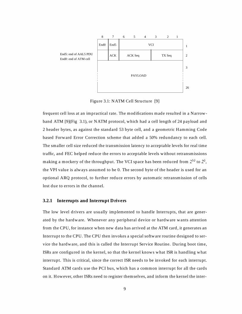
7 6 5 4 3 1
1
2
3
28
VCIEnd0 End5
ACK TX Seq
PAYLOAD
26
ACK SeqEnd5: end of AAL5 PDU
End0: end of ATM cell
Figure 3.1: NATM Cell Structure [9]
frequent cell loss at an impractical rate. The modifications made resulted in a Narrow-
band ATM [9](Fig 3.1), or NATM protocol, which had a cell length of 24 payload and
2 header bytes, as against the standard 53 byte cell, and a geometric Hamming Code
based Forward Error Correction scheme that added a 50% redundancy to each cell.
The smaller cell size reduced the transmission latency to acceptable levels for real time
traffic, and FEC helped reduce the errors to acceptable levels without retransmissions
making a mockery of the throughput. The VCI space has been reduced from 216 to 2
6,
the VPI value is always assumed to be 0. The second byte of the header is used for an
optional ARQ protocol, to further reduce errors by automatic retransmission of cells
lost due to errors in the channel.
3.2.1 Interrupts and Interrupt Drivers
The low level drivers are usually implemented to handle Interrupts, that are gener-
ated by the hardware. Whenever any peripheral device or hardware wants attention
from the CPU, for instance when new data has arrived at the ATM card, it generates an
Interrupt to the CPU. The CPU then invokes a special software routine designed to ser-
vice the hardware, and this is called the Interrupt Service Routine. During boot time,
ISRs are configured in the kernel, so that the kernel knows what ISR is handling what
interrupt. This is critical, since the correct ISR needs to be invoked for each interrupt.
Standard ATM cards use the PCI bus, which has a common interrupt for all the cards
on it. However, other ISRs need to register themselves, and inform the kernel the inter-
9
rupt number for which they need to be evoked. In the case of low level ATM drivers,
the ISRs are composed of top-halves and bottom-halves. The top-half performs the ba-
sic data copying from the hardware memory to local memory and queues up further
processing for the data as a task for the bottom-half. The bottom-half performs the
Data Link level ATM protocol, and hands the data up to the high level driver through
a well defined and consistent interface.
3.2.2 IOCTLs
An IOCTL or I/O control system call is used to manipulate a device driver. It provides
a method for user applications to change the behavior or characteristics of the driver.
The ioctl system call has a uniform interface at the kernel. However, each call has an
argument that targets the call to a specific device driver, and indicates to the driver
what task needs to be performed, or what variable needs to be set. For example, an
ioctl may be used by a program to change the speed of the serial port. IOCTL calls are
performed by opening special files in the file system, called device files. Each of these
files is connected to a device driver.
3.2.3 Multiport Serial Cards
Traditionally, a serial port on a computer has an interrupt associated with it. The
switching function requires a user to be able to connect hosts to the switch, and connect
this switch to other switches so that the hosts can access each other and the rest of net-
work. This requires multiple ATM ports on the switch. Each port handles both input
and output, and has either a host or another switch connected to it. Since each ATM
port is a serial port on the machine, the number of interrupts required for this task soon
becomes prohibitive. The alternative is to use Multiport serial cards. These cards offer
up to 16 serial ports on one interrupt. The ISR associated with the card reads a special
register on the card to determine which of the multiple ports needs servicing. These
cards also provide a host of other features. Each port on the card can usually support
serial data transfer rates of up to 115 kbps. They also have extensive built-in Modem
support. For the NATM Switch, the Cyclades card was chosen. The source code for
10

the driver for this card is available with the Linux distribution, which was modified to
handle ATM traffic over each of the ports.
3.3 Switching in ATM
An ATM switch contains a set of input ports and output ports, through which it is
interconnected to users, other switches, and other network elements. It might also
have other interfaces to exchange control and management information with special
purpose networks. Theoretically, the switch is only assumed to perform cell relay and
support of control and management functions. However, in practice, it performs some
inter-networking functions to support services such as SMDS or frame relay.
It is useful to examine the switching functions in the context of the three planes of
the B-ISDN model [15].
3.3.1 User Plane
The main function of an ATM switch is to relay user data cells from input ports to the
appropriate output ports. The switch processes only the cell headers and the payload
is carried transparently. As soon as the cell comes in through the input port, the Vir-
tual Path Identifier/Virtual Channel Identifier (VPI/VCI) information is derived and
used to route the cells to the appropriate output ports. This function can be divided
into three functional blocks: the input module at the input port, the cell switch fab-
ric (sometimes referred to as switch matrix) that performs the actual routing, and the
output modules at the output ports.
3.3.2 Control Plane
This plane represents functions related to the establishment and control of the VP/VC
connections. Unlike the user data cells, information in the control cells payload is not
transparent to the network. The switch identifies signaling cells, and even generates
some itself. The Connection Admission Control (CAC) carries out the major signaling
functions required. Signaling information may/may not pass through the cell switch
11

fabric, or maybe exchanged through a signaling network such as SS7.
3.3.3 Management Plane
The management plane is concerned with monitoring and controlling the network to
ensure its correct and efficient operation. These operations can be subdivided as fault
management functions, performance management functions, configuration manage-
ment functions, security management functions, accounting management and traffic
management. These functions can be represented as being performed by the func-
tional block Switch Management. The Switch Management is responsible for support-
ing the ATM layer Operations and Maintenance (OAM) procedures. OAM cells may
be recognized and processed by the ATM switch. The switch must identify and process
OAM cells, maybe resulting in generating OAM cells. As with signaling cells, OAM
cells may/may not pass through cell switch fabric. Switch Management also supports
the interim local management interface (ILMI) of the UNI. The Switch Management
contains, for each UNI, a UNI management entity (UME), which may use SNMP.
3.4 Software Switching
Switches are usually built using custom hardware, since they are highly parallel and
speed intensive applications. However, modeling and testing of new and unproven as-
pects of the protocol can be done on software test beds before full fledged investment
into the hardware is made. Software switches usually are a link between network sim-
ulations and hardware implementation of new protocols. If the required bandwidth of
the network is small enough, a software switch might be useful as an actual switching
element. The following sub-sections describe the integral components of a software
switch as implemented for this project.
3.4.1 Switch Structure
As Fig 3.2 shows, the software switch designed has a fully interconnected fabric, a con-
trol layer and minimal management. The switch can support up to 16 serial ports, each
12

of which is controlled by the ATMSL driver running narrowband ATM, with speeds of
up to 115 kbps per port. However, these are theoretical limits. The main constituents
of the NATM switch are
� The switch is built on a PC platform, running Linux. Networking support on
Linux exists in the form of the BSD socket interface. The Linux ATM driver is
patched in to provide ATM Network and Link Layer support.
� The MicroSwitch driver, which implements a fully connected switch fabric is in-
stalled for physical cell switching.
� The Narrowband ATM driver (NATM driver) which uses the serial port to trans-
port narrowband ATM cells is installed.
� The Cyclades multi-port card is used to obtain series of low speed (up to 115
kbps) ports fanning off a single hardware interrupt (section 3.2.3).
� A standard ATM Network Interface Card (NIC) is installed to obtain a fiber chan-
nel to conventional ATM switches.
� Q.Port, a user level signaling application, that implements both host and switch
Call Control, is installed. A new interface between Q.Port and the underlying
MicroSwitch driver is written.
Some of these items are self evident. Salient features of the rest are described below.
3.4.2 The NATM Driver
The Narrowband ATM device driver, adapts a serial port to handle Narrowband ATM
traffic [9]. It is implemented using a top half and a bottom half . It interfaces with the
Linux ATM Driver on one end, and the serial port on the other. The top-half does the
basic copying of data from the interface memory to the local memory. The bottom-half
implements the NATM protocol. The bottom-half contains a round robin scheduler
which looks at the various open VCs and schedules data according to a preset priority
scheme. Real-time (audio) traffic is given priority over data traffic. The traffic priority
13

R
K
E
R
N
E
L
U
S
Fabric
InterfaceOperating System Interface
Switch Call Controller
ESignaling channels
MicroSwitch
Driver
N
T
M
N
A
T
M
E
N
I
A
Cyclades Driver
N
A
T
M
Data channels
Low Level Drivers
(SVCs)
PHYSICAL
LAYERSerial Ports (upto 155 kbps) 155 Mbps
Fibre Channel
Switch Signaling Application (Q.Port)
(PVCs)
ATM DriverLinux
Figure 3.2: The NATM Switch - Block Structure [18]
14

is set using setsockopt() call during connection set-up. the The scheduler is followed by
a Segmentation and Reassembly layer, to handle the various ATM Adaptation Layer
types as defined by the ATM Forum. The SAR layer queues fully formed ATM cells to
the port in the transmit direction, and fully assembled PDUs to the ATM interface in the
receive direction. The cells pass through an (optional) FEC module that adds the error
correction to the cell, and the bytes are then placed at the serial port. The interface
to the serial port is modular. In the case of the NATM switch, the serial interface is
replaced with an interface to the Cyclades Multiport card. The NATM driver registers
itself with the ATM driver for each of the active ports below that it is configured to
handle. It instantiates local data structures for each of the ports, which contain data
to be transmitted and data received on that port. It wakes up the appropriate port on
multiport cards on switches (the default serial port on hosts), each time there is data to
be transmitted. The receive section is woken up by the interrupt handler for the port
when data arrives.
3.4.3 The MicroSwitch Driver
The MicroSwitch driver is a simple cell level switching driver that is implemented for
Linux. It has an ioctl() based interface, which can be used to connect and disconnect
a VC on a port to another VC on a different port. The connection is bidirectional.
Cells arriving on either VC are then dequeued, and queued on the outgoing queue of
the complimentary VC. The driver does rudimentary traffic management by blindly
dropping cells if any of the destination queues become too long. The switching is cell
based in the sense that no SAR functions are implemented in the driver and all the
cells are treated as raw ATM data (AAL0). Provision has been made to allow optional
switching of data as arbitrary length AAL5 packets.
3.4.4 Q.Port
Q.Port [21] implements signaling stacks on a configurable number of ports. It provides
both UNI and IISP stacks, and a fabric controller. There are a few standard fabrics
supported by the application, however a well defined fabric interface allows one to
15
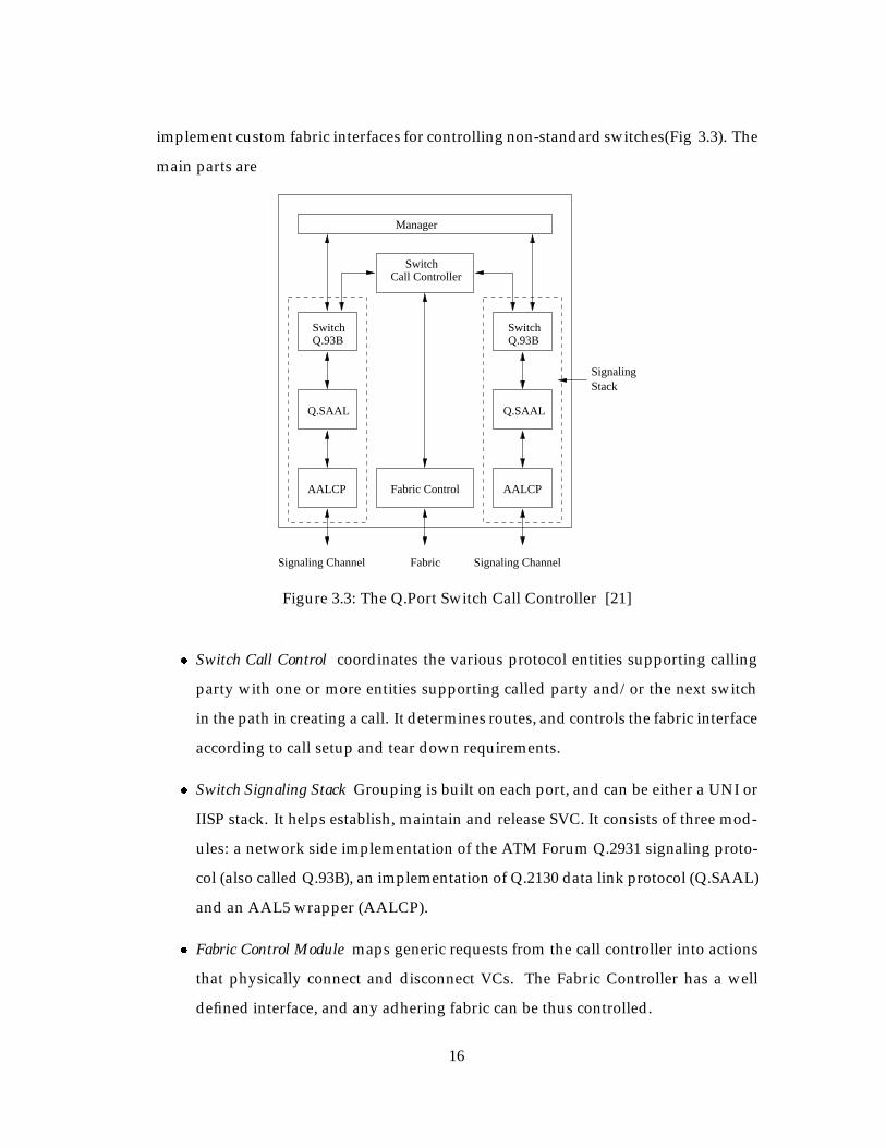
implement custom fabric interfaces for controlling non-standard switches(Fig 3.3). The
main parts are
AALCP AALCP
SwitchCall Controller
Fabric Control
Q.93BSwitch
Q.SAAL
SwitchQ.93B
Q.SAAL
Manager
Fabric Signaling ChannelSignaling Channel
SignalingStack
Figure 3.3: The Q.Port Switch Call Controller [21]
� Switch Call Control coordinates the various protocol entities supporting calling
party with one or more entities supporting called party and/or the next switch
in the path in creating a call. It determines routes, and controls the fabric interface
according to call setup and tear down requirements.
� Switch Signaling Stack Grouping is built on each port, and can be either a UNI or
IISP stack. It helps establish, maintain and release SVC. It consists of three mod-
ules: a network side implementation of the ATM Forum Q.2931 signaling proto-
col (also called Q.93B), an implementation of Q.2130 data link protocol (Q.SAAL)
and an AAL5 wrapper (AALCP).
� Fabric Control Module maps generic requests from the call controller into actions
that physically connect and disconnect VCs. The Fabric Controller has a well
defined interface, and any adhering fabric can be thus controlled.
16

3.5 Signaling on the End System
Signaling on the end system is performed by a set of daemons that are part of the ATM
driver for Linux. There are essentially three important signaling daemons.
3.5.1 ATMSIGD
Atmsigd is the UNI signaling daemon for the Linux ATM [27]. It implements the UNI
3.1 signaling stack for a single ATM interface on the host (Fig 3.4). The signaling dae-
daemonApplication
Signaling NetworkKernel
UNI signaling (Q,2931)
Internal Signaling Protocol
Figure 3.4: Linux ATM Signaling
mon implements the UNI signaling complexity as part of user space, while a simple
protocol to support ATM signaling resides in the kernel. The user process communi-
cates with the kernel using a simple Internal Signaling Protocol, which relies on the
well ordered nature of the system to manage the signaling. The ISP uses synchronous
communication based on BSD sockets.
3.5.2 ILMID
Ilmid is the Interim Local Management Interface daemon that is used to manage the
host status and configuration, perform address registration and update at the switch.
It uses existing SNMP standard, and defines a new ATM UNI Management Informa-
tion Base (MIB) to perform VC status and management, operational measurement as
required, diagnostics, etc [7].
17

3.5.3 ATMARPD and ATMARP
Atmarp is used to resolve IP addresses over an ATM subnet. The ATMARP requests
and replies are sent using AAL5. The ATMARP structure consists of an ARP Server,
whose ATM address is well known within the subnet. Hosts wanting to resolve IP ad-
dresses to their respective ATM addresses send queries to the ARP server, which looks
up its data base and responds with the required address. The ARP server updates it’s
data base when it receives ARP requests by sending inverse ARP or InARP REQUEST
to the originating host for each logical IP subnet the server is configured to serve. In
the event that the server is unable to find the corresponding entry in its table, it returns
an ARP NAK to the host.
The ARP client is responsible for contacting the ARP Server with its own IP ad-
dress to register itself. This usually happens at boot-up time. It is also responsible to
initiate and maintain a VC to the ARP server, respond to ARP and InARP requests,
and generate and transmit ARP REQUEST when required by applications wishing to
make connections.
3.6 Real-time Transport Protocol - RTP
RTP is the Internet-standard protocol for the transport of real-time data, including au-
dio and video. It has been designed within the Internet Engineering Task Force (IETF)
[24]. It can be used for media-on-demand as well as interactive services such as Inter-
net Telephony. RTP consists of a data and a control part. The latter is called RTCP. If
RTP packets are carried in UDP datagrams, data and control packets use two consec-
utive ports, with the data port always being the lower one. If other protocols serve
underneath RTP (e.g. RTP directly over ATM AAL5), other schemes have to be used.
While UDP/IP is its initial target networking environment, efforts have been made
to make RTP transport-independent so that it could be used, say, over CLNP, IPX or
other protocols. RTP is currently also in experimental use directly over AAL5/ATM.
RTP does not address the issue of resource reservation or quality of service control;
18

instead, it relies on resource reservation protocols such as RSVP.
3.6.1 RTP Data Packets
The data part of RTP is a thin protocol providing support for applications with real-
time properties such as continuous media (e.g., audio and video), including timing
reconstruction, loss detection, security and content identification.
P X M Payload Type
Sequence Number
Timestamp
Timestamp (contd)
Synchronization source (SSRC) identifier
SSRC (contd)
X - eXtension
Contributing source (CSRC) identifiers
CSRC (contd)
V-Version CSRC count
Fixed
Optional
0 1 2 3 4 5 6 7 8 9 0 1 2 3 4 5
0 1
V - Version
P - Padding
M - Marker
Figure 3.5: RTP Header Structure [24]
The RTP header format is shown in Figure 3.5. RTP data packets consist of a 12-byte
header followed by the payload e.g. a video frame or a sequence of audio samples. The
payload may be wrapped again into an encoding-specific layer. The header contains
the following information:
� Payload type: A one-byte payload type identifies the kind of payload contained
19

in the packets, e.g. JPEG video or GSM audio
� Timestamp: A 32-bit timestamp describes the generation instant of the data con-
tained in the packet. The timestamp frequency depends on the payload type.
� Sequence number: A 16-bit packet number allows loss detection and sequence
within a series of packets with the same timestamp.
� Marker bit: The interpretation of a marker bit depends on the payload type. For
video, it marks the end of a frame, for audio, it marks the beginning of a talkspurt.
� Synchronization source (SSRC) identifier: A randomly generated 32-bit scalar
that uniquely identifies the source within a session.
Some additional bit fields are not described here for brevity.
3.6.2 RTP Control Functionality
RTP offers a control protocol called RTCP that supports the protocol functionality. An
RTCP message consists of a number of stackable packets, each with its own type code
and length indication. Their format is fairly similar to data packets; in particular, the
type indication is at the same location. RTCP packets are multicast periodically to the
same multicast group as data packets. Thus, they also serve as a liveness indicator of
session members, even in the absence of transmitting media data. RTCP is scalable and
provides support for real-time conferencing of groups of any size. RTCP provides the
following functionality:
� QoS monitoring and congestion control
� Inter-media synchronization
� Identification
� Session size estimation and scaling
20

3.7 Congestion Control
Congestion Control is important in high-speed networks in order to achieve network
performance objectives and at the same time increase the network utilization. Conges-
tion control schemes can be broadly classified into two categories: preventive schemes
and reactive schemes [20]. In preventive schemes, the goal is to avoid congestion
within the network. Reactive schemes control the congestion once it occurs in the net-
work. Figure 3.6 shows the categorization of some of the schemes that are proposed.
SelectiveDiscarding
Traffic Shaping
Excess TrafficMarking
In-Call parameterNegotiation
CellTime
PropagationDelay Time
ConnectionDuration
Long Term
Adaptive Windows Adaptive Ratecontrol
Dynamic Source Coding
ResourceProvisioning
Call Routing
Call Admission Control
Traffic Policing
Tim
e Sc
ale
of C
ontr
ol
Preventive Control Reactive Control
Figure 3.6: ATM Congestion Control Options [20]
Preventive schemes: In these schemes, the connection’s traffic is estimated a priori
and allocated sufficient amount of bandwidth. The connection is expected to remain
within the limits of its allocated bandwidth. These schemes require accurate modeling
of short and long term traffic patterns in order to satisfy the objectives of network. This
21

is not a very easy task.
Reactive schemes: These are usually used as backup for preventive schemes, or as
an aggressive control to maximize network utilization. The primary disadvantage of
this scheme is their inefficiency in an environment with large delay-bandwidth product
which causes large delay to the feedback information which is used by points within
the network to regulate traffic. Hence, in the current implementation, the reactive
schemes are used with a difference. A source-independent rate translation mechanism
is used, whereby no feedback information needs to be sent and hence delay-bandwidth
product is not a problem. The rate translation is made possible by using the STC ex-
plained in Section 3.9. Encoding, decoding and rate-translation is done using RAT
explained in Section 3.8.
3.8 Robust Audio Tool - RAT
RAT is a network audio tool that allows users to participate in audio conferences over
the internet. These can be between two participants directly, or between a group of
participants on a common multicast group. No special features are required to use
RAT in point-to-point mode, but to use the multicast conferencing facilities of RAT, a
connection to the Mbone, or a similar multicast capable network, is required. RAT is
based on IETF standards, using RTP [24] above UDP/IP as its transport protocol, and
conforming to the RTP profile for audio and video conference with minimal control.
In addition to the features provided by other Mbone audio conferencing tools, such
as vat, RAT offers the following additional functionality:
� Sender based repair of damaged audio streams
� FEC in the form of redundant packet transmission
� Support for interleaved audio
� Received based repair of damaged audio streams
� Adaptive scheduling protection
22

� Secure conferencing
� Improved statistics and diagnostic features
� Conference coordination bus
� Transcoder operation
Of interest is the transcoder operation, which can be used in congestion manage-
ment. When the bandwidth available is not constant for all participants in a con-
ference, or when some participants do not have multicast capable access, the RAT
transcoder/gateway may be used. This connects two multicast groups, or one mul-
ticast group and a single unicast host. RTP packets received from either group are
transcoded into the format specified for the other group, multiple sources are mixed
together, and the resulting stream is transmitted to the other group. This allows for
different codecs to be used in each group, meaning that the bandwidth requirements
are different. Thus, when sending out data on a congested link data coded in one for-
mat can be transcoded into another format with lower bandwidth requirement.
It is supported on a range of platforms: FreeBSD, HP-UX, IRIX, Linux, Solaris,
SunOS, and Windows 95/NT. The source code is publicly available for porting to other
platforms and for modification by others.
3.9 Speech Coding and Sinusoidal Transfer Coder - STC
Since the project deals with narrowband communication, it is required that a low bit
rate speech coder be used to provide efficient resource usage on the low bandwidth
links. Also, it is required that the speech coder supports source-independent rate
translation capability where it is possible to transform the bit rate of the coded speech
stream at any intermediate node in the network, without interaction with the source.
This feature is used in congestion control where the Active Node transcodes audio on
the congested links to lower bit rates to ease congestion.
23

Encoder Linear 16 PCM DVI GSM LPC STCCoding Rate (kbps) 128 64 32 13.2 5.8 4.8
Encoded audio bytes/frame 320 160 80 33 14.5 18RTP header bytes/frame 12 12 12 12 12 12
AAL5 Trailer (bytes) 8 8 8 8 8 8Total bytes per frame 340 180 100 53 34.5 38
NATM cells/frame 15 8 5 3 2 2Framelength (ms) 20 20 20 20 20 30
Frames/sec 50 50 50 50 50 100/3Bandwidth/RTP stream 156 83.2 52 31.2 20.8 13.87
(kbps)
Table 3.1: Comparison of Bandwidth Requirements of Different Coding Techniques
Table 3.1 gives a comparison of bandwidth required to transfer audio encoded us-
ing different codecs using RTP embedded in AAL5 packets. Since the maximum link-
bandwidth in the current narrowband network is 38.4 kbps, only 3 codecs can be used
within the narrowband environment. However, STC has a few more advantages to its
usage as mentioned below.
Standard low and medium bit-rate coders provide efficient and good quality speech
output, but do not adequately support the source-independent rate translation capa-
bility, which is a requirement for the current project. The solution that the current
project employs is to use embedded coders, where the parameters of the lower rate
coder are embedded in the parameters of the higher rate coder [5]. To reduce the bit
rate, the higher rate parameters are stripped off. The Sinusoidal Transfer Coder (STC)
[17, 16] allows inter-operability at different rates and source-independent rate transla-
tion using bit-dropping technique. The STC is a vocoding technique which represents
the excitation signal as a sum of sine waves of arbitrary amplitudes, frequencies and
phases. The STC uses FFT to generate a set of cepstral coefficients which are coded and
transmitted along with excitation parameters. STC is a multirate coder which operates
at several discrete rates from 8 kbps to 2.4 kbps. In the current project, STC normally
operates at 4.8 kbps. During congestion, STC performs bit-dropping and produces
voice coded at 2.4 kbps.
24

3.10 Magician - An Active Networking Toolkit
To understand the strengths and limitations of Active Networking, Magician [14], a
toolkit for creating a prototype Active Network was developed at the University of
Kansas. In an Active Network, program code and data is placed inside specialized
packets called SmartPackets. The nodes of an Active Network are called active nodes
and they are programmable in the sense that when a SmartPacket reaches an active
node, the code inside the SmartPacket is extracted and executed. Depending on the
nature of the code inside the SmartPacket, the SmartPacket either modifies the behav-
ior of the active node or transforms the data it is carrying. Magician provides the
platform on which active nodes can run, and the tools and interfaces for creating new
SmartPackets and deploying new services and protocols in the Active Network. The
basic implementation uses UDP/IP combination for transport and routing.
The two principal components of an Active Network are the active nodes and
the SmartPackets. The prototype Active Network is a collection of individual active
nodes and a single Information Server each running on a separate Java Virtual Ma-
chine (JVM). Active nodes exchange SmartPackets by encapsulating them inside UDP
packets and sending them on UDP ports 3322-3325 of the host on which a neighbor-
ing active node is running. An Information Server maintains the configuration of the
network. At startup, nodes in the Active Network contact the Information Server to
determine adjacent nodes. This information is useful to provide a basis for developing
the infrastructure necessary for routing SmartPackets in the Active Network.
Magician is implemented in Java. The Java Virtual Machine environment supports
machine-independent programs and the language is quickly becoming a standard for
object-oriented programs that can be compiled into bytecodes. It was opted to imple-
ment the system using version 1.1 of the Java Development Kit (JDK) for two principal
reasons:
25

� It supports object serialization which allows transport of state across the network
in SmartPackets, and Version 1.1 is expected to be forward-compatible with fu-
ture versions as opposed to version 1.0.2.
� Since SmartPackets are executable entities, their state has to be preserved when
they are transported from one active node to the next. Object serialization is
one technique for preserving and transporting state. The state of an executing
object is written out as a byte array in a particular format. The byte array is then
transported across the network to the neighboring active node where the bytes
in the array are used to re-create the SmartPacket. There is an added advantage
in using object serialization. Since Java is being becoming increasingly popular
in the Active Networking community, it is expected that most active nodes will
support object serialization. This permits widespread integration of the different
active network architectures.
3.10.1 SmartPackets
In an Active Network, data packets are information entities. These entities, called
SmartPackets, contain a destination address, user data, and methods that can be ex-
ecuted locally at any node in the Active Network. SmartPackets carry customized
protocols that are fitted in with protocol modules at the network nodes.
The code in the SmartPacket can be in any executable format and it is executed at
the node if the node has the correct processing environment. In Magician, the code of
the SmartPacket is actually a Java class that describes the methods that act on the user
data. Each SmartPacket has a 128-bit type identifier, which is used to identify the pro-
tocol that is carried by the SmartPacket. The type identifier is a MD-5 message digest
of the structure of the SmartPacket.
The idea is that any composer of a SmartPacket (user, application, router etc.) want-
ing to define a new type sends the SmartPacket definition to a local Type Authority
26

(currently built into the kernel at the host node). This Type Authority authenticates
the composer, checks the structure of the SmartPacket and converts the SmartPacket
definition to canonical form. The canonical form is then hashed (using a standard hash
algorithm) into a 128-bit number that is returned as the type identifier for the Smart-
Packet. This prevents spoofing because the signature is a one-way function and the
contents of the packet can be verified against the signature.
Environment ID
Active Network Encapsulation Protocol (ANEP)
TLV - type/length/value tuple
Header
Source Address TLV
Destination Address TLV
128 bit Type Identifier TLV
KU SmartPacket Object (Java Serialized Object)
Figure 3.7: On-The-Wire Format of SmartPacket [14]
The overall structure of the SmartPacket conforms to the Active Network Encap-
sulation Protocol (ANEP). ANEP was created to enable members of the Active Net-
working community to implement their own execution environments at all member
sites and still be able to interchange SmartPackets. The ANEP structure shown in Fig-
ure 3.7 consists of a fixed header that describes, among other things, the environment
in which this SmartPacket executes, and a series of optional type/length/value (TLV)
tuples. Some of the TLVs defined in the ANEP proposal are source definition TLV, des-
tination definition TLV and authentication TLV.
27
Members are free to add their own TLVs to the overall structure except that they
will not processed at nodes which do not understand them. In Magician, a class defi-
nition TLV was developed to carry the Java class definition of the user code. Also, an
object definition TLV was defined to carry the serialized object and a Type definition
TLV that carries the type identifier of the SmartPacket.
3.10.2 Active Nodes
Active nodes perform the functions of receiving, scheduling, executing, monitoring
and forwarding SmartPackets. When a SmartPacket arrives at an active node, the type
identifier and the user-defined code inside the SmartPacket is extracted. The type iden-
tifier is used to de-multiplex the SmartPacket to its correct processing environment.
The SmartPacket is then scheduled for execution. A separate environment is required
for each invocation to prevent undesirable interactions and malicious access to node
resources.
Active nodes export a set of resources and primitives that can be used by the user
programs contained inside SmartPackets. This not only provides a consistent view of
the network but also enforces constraints on the actions that can be performed by user
code. Thus an active node enforces a time limit on the execution of SmartPackets to
prevent runaway user programs. It also imposes a limit on the total memory that can
be requested by a SmartPacket. In terms of primitives, user code has restricted access
to certain internal information such as the routing tables, buffer space information and
available link bandwidth on the node’s interfaces. The user can utilize this information
to develop application specific strategies to combat congestion or implement a new
routing policy for its packets.
3.10.3 Active Node Architecture
The model of an active node is shown in Figure 3.8. An active node is made up of
(possibly) multiple processing environments such as a PLAN execution environment
or an ANTS environment. Each environment is controlled by its node manager. When
28

Port
Manager
Routing
Manager
PacketizerScheduler
Node Resources
Net EventManager
Node Manager
ACTIVE NODE
Resource ManagerKU SmartPacket
Control flow
Data flow
UDP Packet
ANEP packet
UDP Packets
Demultiplexer
To other Active
Environments
SmallState
Manager
SmartPacketThreads
Figure 3.8: Model of Magician Active Node [14]
an active node boots up, it starts a set of port managers, a demultiplexer, and the node
managers of all the environments that the active node supports. There is one Port
Manager per UDP port that the active node listens to and on which the active node
communicates with other nodes. The list of ports that the active node listens to is ob-
tained from the Information Server at boot time. Incoming SmartPackets are queued
at the Demultiplexer. The Demultiplexer verifies that the packet conforms to ANEP
standard and then attempts to demultiplex the packet to its correct processing envi-
ronment based on the environment identifier field in the header. This is accomplished
by using the environment identifier to index into a table to find the Node Manager
for the environment. The byte stream constituting the packet is then handed over the
environments node manager.
3.10.4 Node Manager
In this approach, the Node Manager starts other managers such as the resource man-
ager, the routing manager, the network event reporting manager and the port interface
29

manager. The resource manager is involved in the management of node resources in-
cluding scheduling and is discussed in the next section. The routing manager provides
the interface for installing routing protocols and also provides a default routing mech-
anism for those SmartPackets that do not implement their own. More details about the
routing manager are discussed in Section 3.10.6.
The port interface manager controls the assembly and disassembly of SmartPack-
ets and their transmission and reception over the wire. The port interface manager
receives a SmartPacket as a byte stream. The ANEP header is peeled off first. The
TypeID TLV describes the type of the SmartPacket. If the node is receiving a packet
of that type for the first time, a new SmartPacket loader is created. The SmartPacket
loader extends the normal Java Virtual Machine class loader by allowing new classes
to be loaded from packets received over the network. The SmartPacket loader is then
assigned to that type and is used whenever packets of that type are received or need to
be transmitted. This also presents a separate environment for each type so that there
are no name conflicts between SmartPackets of different types. Name conflicts between
packets of same types are treated as errors.
To construct an incoming SmartPacket, the SmartPacket loader reads the bytecodes
representing the class definition and the serialized object. After reading the Smart-
Packet, the classes, if any, in the SmartPacket are loaded and verified by the Smart-
Packet loader. The serialized object is de-serialized and checked for the presence of
resource information. This resource information includes resource requirements like
maximum processing time, which are passed to the Resource Manager along with the
de-serialized object for processing.
The port interface manager reverses the process when transmitting SmartPackets.
When it receives the SmartPacket object and information about its next hop, the ob-
ject is serialized and placed in the Object Definition TLV, the ANEP header and other
appropriate TLVs are added and the byte stream is transmitted on the appropriate link.
30

Serialization of a Java object is an expensive operation. Therefore, when a Smart-
Packet is received a hash is computed on the extracted data object and the object is
cached. This hash is used when the same SmartPacket is ready for forwarding to deter-
mine if the entire object needs to be re-serialized. If nothing in the object has changed,
simply re-sending the original cached object can save time.
3.10.5 Resource Manager
When a SmartPacket arrives at an active node, the Node Manager verifies, loads, and
defines the embedded class to the execution environment as described earlier. The
Node Manager then forwards the de-serialized code object to the Resource Manager
for execution. The Resource Manager provides an interface to resources at the node.
The code in the SmartPackets is run in a thread. All requests for resources are made
by the thread on behalf of the code. This is similar to the path abstraction used in the
Scout operating system. Having a single thread per SmartPacket simplifies resource
management because it is easy to track the resources allocated for a given thread.
Most SmartPackets arriving at an Active Node do not require sophisticated re-
source models. Some of the basic resources are CPU cycles, memory and I/O band-
width. This list can be extended by including storage in which SmartPacket can leave
small state at a node after its execution environment expires.
3.10.6 Routing
The Routing Manager maintains the interfaces for various routing protocols to be im-
plemented. The default routing protocol that is installed at all active nodes is the RIP
routing protocol. The RIP routing protocol creates and maintains its own routing ta-
bles and provides the interface for manipulating these tables. The routing table is a
simple vector of 4-tuples that describes other active nodes in the network and how
to get there. But instead of sending routing table updates as data, the active routing
protocol sends SmartPackets that carry code to modify, add or delete table entries at
31

the destination. Users can install their own routing protocol for their SmartPackets by
overriding the GetNextHop method of the base SmartPacket class by a method which
returns the name of the active node that serves as the next hop towards the destination.
3.10.7 Four11 Server
The Four11 server (class Four11) is an information service that maintains information
about named, virtual active networks. The idea is that the physical network of active
nodes can be overlaid by a virtual network of nodes. Thus a physical Active Network
can contain multiple virtual active networks (VAN). Information about each VAN is
maintained by the Four11 server. Any active node can query the Four11 server through
a specific API to obtain information about a VAN or its constituent nodes. Information
such as the names of the active nodes in a VAN, the physical nodes on which they
reside, the interface addresses, their neighbors in the VAN can be easily determined.
32

Chapter 4
Implementation
4.1 Narrowband ATM Testbed
4.1.1 Software-Switch
The software switch has been developed by modifying the Linux operating system
version 2.1.105 with Linux-ATM version 0.38. The hardware interfaces used have been
discussed in Section 3.4. The granularity of the Linux heartbeat has been improved
from 10 milliseconds to couple of microseconds using UTIME [23]. This additional
resolution is required to precisely match the cell switching rate on each switch port to
that of the line rate of the port e.g. 38.4 kbps is the line-rate on a Cyclades serial port,
hence 26 byte NATM cells will have to be switched every 5.416 milliseconds, which is
possible only with the improved heartbeat granularity.
The working of the MicroSwitch Driver has been explained in Section 3.4.3. The
basic driver, however, does not differentiate between ATM cells depending upon the
payload, QoS etc. Also, cell-switching is entirely a kernel space activity. In order that
a switch behave as an active node, the switched ATM data should be accessible from
user space. The following sections describe the modifications to the driver design.
4.1.1.1 Class-Based Queuing
The MicroSwitch driver accomplishes the task of switching cells from an incoming
(Port, VC) onto an outgoing (Port,VC), based on the contents of a routing table that
33

Weighted Round-Robin scheduling
Input VBR Queue Output VBR Queue
Output UBR Queue
Output Port B
Transfer from input to output queue after port delay
Input UBR Queue
AAL5 packets
AAL0 cells
Programmed Port DelayInput Port X
VBR Service Priority higher than
Input Port A
UBR Service Priority
Output Port Y
Figure 4.1: Class-Based Queuing
it maintains. It provides output queuing and implements per-class queuing with sep-
arate queues for different traffic types at the output of each of the ports as shown in
Figure 4.1. For the current implementation, the classes were defined to be audio and
data. Alternatively, audio can be called Variable Bit Rate (VBR) traffic, given the na-
ture of silence-suppressed audio and its time-critical aspect. Data can be considered
to be Unspecified Bit Rate (UBR) traffic considering non time-critical nature of data.
Thus, the switch has separate queues for VBR and UBR traffic at the output of each of
the ports. The VBR and UBR queues are serviced by a weighted round-robin sched-
uler with VBR:UBR weight ratio equal to 10000:1. This is done to ensure that audio
is switched whenever it is ready for delivery irrespective of the fact that data may al-
ready be queued for switching. This ensures that audio QoS is maintained.
Ordinarily, the MicroSwitch driver switches AAL0 cells i.e. it opens AAL0 sock-
ets for the incoming VC and outgoing VC and receives AAL0 (raw ATM) cells and
switches AAL0 cells. This is under the assumption that the switch will not be process-
ing the payload contained in the ATM cells. However, as mentioned in Section 1, in
an Active Network, switches perform computations on user-data as the data traverses
the network. In this case, the user-data is audio traffic. The encapsulation that is used
for audio traffic is AAL5 packets containing encoded audio embedded in RTP packets.
Thus, the switch is required to open AAL5 sockets for audio traffic and switch audio
34

as AAL5 packets and not AAL0 (raw ATM) cells so that the payload can be retrieved
correctly in user-space by the active node for processing when required. Data traffic on
the other hand, will not be processed by the Active Network. Hence, data is switched
as AAL0 cells. In the current implementation, this distinction in traffic type is made
after connection set-up. During connection set-up, the switch call-controller (Q-Port),
makes a connection between the inport and outport. Once the connection is made,
the end-hosts transmit a special identifier on the connection. On each connection, the
switch checks the first AAL0 packet that it receives. If the packet, contains the magic
string ”AN” within the identifier, the switch identifies the connection to be carrying
audio traffic and expects that all cells coming then onwards are AAL5 encapsulated.
The special identifier is not sent on connections carrying data traffic by the end-hosts.
Thus, audio traffic is switched as arbitrary-sized AAL5 packets and data traffic as
fixed-sized AAL0 cells. This implies that the scheduler which is used for switching
cells onto outgoing links cannot switch out packets at all switching intervals. As ex-
plained, the switching interval is calculated considering that fact that NATM cells with
24-bytes payload are to be switched. The AAL5 audio packets can be of more that
24 bytes. Hence, the successive AAL5 packets/AAL0 cells for the same output port
should be re-scheduled considering the length of the AAL5 packets. This timing ad-
justment is not necessary after an AAL0 cell is switched. This scheme is shown in
Figure 4.1. Each AAL5 packet/AAL0 cell that arrives on a port is transferred to the
respective port input queue. Each cell undergoes a specific port delay in the input
queue before it is transferred to the output queue. Once the packet/cell is in the out-
put queue, it will be switched out at the earliest switching interval after it reaches the
head of the queue and the VBR/UBR priority scheme is resolved. The port delay, by
default, is zero seconds. However, if an AAL5 packet of length greater than 24 bytes is
being switched out, the port delay for that port is adjusted proportionately. Thus, usu-
ally there is only only packet/cell in either of the 2 output queues on one output port.
The input queue will contain more than one entity each. This scheduling regulates the
flow of cells on the link connected to the port.
35

4.1.1.2 Active Network Processing
During connection set-up, the MicroSwitch creates a data structure which maintains
the state for the connection. This data structure maintains information for different
functions such as whether the packet on the connection is the first packet or not, what
is the special identifier that was sent in the first packet transmitted on the connection
etc. Also, at connection set-up, the MicroSwitch assigns each connection a switch-wide
unique VCI number from a reserved range of VCI numbers. No PVC/SVC connection
will ever be assigned VCIs from that range. The VCI number is called the Active VCI.
Immediately after connection set-up, the Active Manager opens PVC sockets on the
input port and output port of the connection using the Active VCI. Normally, data is
switched using the class-based queuing. However, when Active Processing is desired
the AAL5 packets on the active connection traverse a different path. In the current
implementation, Active Processing is desired whenever congestion occurs in the in-
put queues for an output port. In such a case, after the AAL5 packet enters the input,
instead of being queued in the input queue for output port, the packet is sent on the
PVC opened by the Active Node Manager on the Active VCI on the input port. The
Active Node Manager extracts the RTP packets from the AAL5 packets, processes the
encoded audio, re-encapsulates in AAL5 format and writes the AAL5 packet to the
same PVC it reads the packet from. In the kernel, the MicroSwitch driver interpretes
from the VCI number that the packet has been processed by the Active Node Man-
ager and then queues up the packet on the input queue for the destined output port
it is to be switched to. The path that the AAL5 packet then follows is the same that it
would follow if there were no Active Processing. Figure 4.2 shows the flow-chart for
the cell-reception by the MicroSwitch. Figure 4.3 shows the flow-chart for the queuing
and switching scheme of the MicroSwitch. Figure 4.4 shows the diagrammatic imple-
mentation of the switching scheme.
36

return
Is ActiveProcessingrequired?
return
Is it on anActive VCI ?
Receive data from user processfor sending to hardware
Send data to device driverafter relevant encapsulation
return
after setting appropriate delay
Is it anActive
Receive ATM cell / packet from
hardware on VC n of Port A
Connection?
No Yes
No Yes
YesNo
Queue data on socket receivequeue of Active VCI for that port,
to be passed to the ActiveManager
Transfer to Input queue of Port B
Figure 4.2: Flow-chart for Cell Reception by the MicroSwitch Driver
4.1.2 End-Hosts
Section 4.1.1 describes the class-based queuing on the software switch. Similarly, it is
necessary to differentiate traffic on the end-hosts viz. audio and data traffic. The traffic
on a particular connection is identified using a setsockopt() call after the connection. By
default, all connections carry data traffic i.e. UBR. The setsockopt() call sets the connec-
tion type to VBR. This implementation assumes only one ATM port on the end-hosts.
So, class-based queuing is implemented for one port only. A round-robin scheduler
services the 2 queues, where the weights assigned to VBR:UBR are in the ratio 10000:1
to give maximum priority to audio traffic.
4.2 Active Network
This section describes the implementation of the Active Network architecture em-
ployed for the current project.
37

Update port delay
return return return
Invoke Round-Robin Scheduler
Is length ofpacket > 1 cell
payload
Switching Timer Handler
UBR?
UBRVBR
UBRVBR
Yes No
Determine output VC m , output port Bfor all cells whose Port delay has expired
Transfer to UBR Queueof Port B
Transfer to VBR Queueof Port B
type(m)VBR orUBR?
type(m)VBR or
Figure 4.3: Flow-chart for Queuing, Switching and Active Processing Scheme
38

Active ManagerUserSpace
KernelSpace
ATM Interface Cards
ATM Driver LayerSubsystem
Switching Subsystem:MicroSwitch Driver
Cell on Incoming VC Cell on Outgoing VC
Path taken during normal switching
Path taken during Active Processing
Q-Port Signaler
Figure 4.4: Implementation of Queuing, Switching and Active Processing Scheme
39

4.2.1 Modifications to Magician
Section 3.10 gives a detailed explanation of the Magician architecture. The following
are the differences which require modification to the Magician architecture to adapt it
to the current Narrowband ATM network.
� Magician identifies active nodes using IP host address and UDP port combina-
tion. These identifiers are stored in the Information server.
� Magician uses connectionless UDP sockets to transfer to and from the network.
� Magician uses Java as the implementation language. Java provides a set of li-
braries for managing UDP sockets.
� Magician uses an in-band loading scheme for programming the nodes. Program
code and data are sent in the same SmartPacket.
We contrast below, the features of Magician on an IP network with the nature of the
Active Narrowband network.
� The Narrowband ATM Network as the name says is an ATM network. Hosts
and Software switches and thus active nodes are identified using ATM interface
address.
� To make connections over an ATM network, PVC or SVC sockets are required.
These sockets are connection-oriented.
� Java does not provide support for ATM socket through its libraries.
� The Narrowband ATM Network uses low-bandwidth links to interconnect hosts,
unlike in Magician over IP which assumes Ethernet as the physical medium. The
program code is of significant size to cause a long delay in transfer of the Smart-
Packets, if data and program code are sent together. This needs to be avoided by
pre-installing the program code on the active nodes using SmartPackets.
40
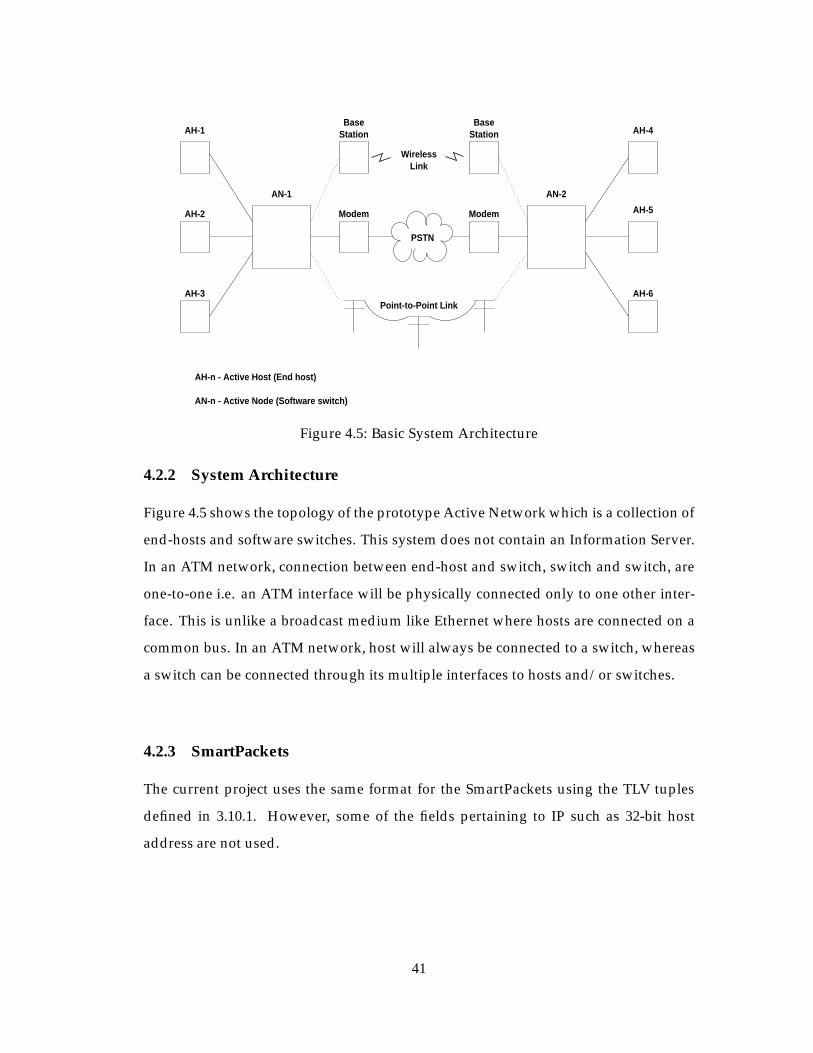
StationAH-1
AH-2
AH-3
AN-1
AH-n - Active Host (End host)
AN-n - Active Node (Software switch)
AH-4
AH-5
AH-6
AN-2
PSTN
Point-to-Point Link
WirelessLink
Modem Modem
BaseStation
Base
Figure 4.5: Basic System Architecture
4.2.2 System Architecture
Figure 4.5 shows the topology of the prototype Active Network which is a collection of
end-hosts and software switches. This system does not contain an Information Server.
In an ATM network, connection between end-host and switch, switch and switch, are
one-to-one i.e. an ATM interface will be physically connected only to one other inter-
face. This is unlike a broadcast medium like Ethernet where hosts are connected on a
common bus. In an ATM network, host will always be connected to a switch, whereas
a switch can be connected through its multiple interfaces to hosts and/or switches.
4.2.3 SmartPackets
The current project uses the same format for the SmartPackets using the TLV tuples
defined in 3.10.1. However, some of the fields pertaining to IP such as 32-bit host
address are not used.
41

4.2.4 Active Nodes
The active nodes perform the validation, scheduling and sand-boxing as mentioned in
Section 3.10.2.
4.2.5 Active Node Architecture
Packetizer
Object
Code
Repository Installer
Object
Code Software Switch - Kernel Component
Scheduler
Installer
Class
Manager
Connection
Port
Program Code Threads
Demultiplexer
ACTIVE NODE
Resource Manager
Threads
SmartPacket
Node Manager
AAL5 data PVCs
KU SmartPacket
Control flow
Data flow
AAL5
ANEP packet
Managers
switches
AAL5 PVCs on ControlVCI to other hosts/
Connection
(Ethernet)
FastInterface
Routing
Manager
Figure 4.6: Active Node Architecture
The model of an active node in the Narrowband ATM network is shown in Fig-
ure 4.6. An active node is made up (possibly) multiple processing environments such
as a PLAN execution environment or an ANTS environment. In the current imple-
mentation, we assume only one execution environment. When an active node boots
up, it starts a set of Port Managers, a Demultiplexer, and the Node Managers for the
environments that the active node supports. There is one Port Manager per ATM in-
42

terface on the end-host/switch. Usually end-hosts have only one ATM interface, and
hence only one Port Manager will start up. On a switch, there will be one Port Man-
ager for each enabled ATM interface. The list of interfaces is obtained by querying
the MicroSwitch through ioctl() calls using Java Native Interface (JNI). Since no infor-
mation about the switch is available through standard system calls and Java does not
provide support through its libraries, a library had to be created wherein native func-
tions are implemented which query the switch for different bits of information using
ioctl() calls and return information to the Active Manager using Java Native Interface
[12]. The Port Manager opens a PVC socket on a unique VCI (62) called Control VCI
on each of the enabled interfaces. Since Java does not provide socket API for ATM,
an API was defined and implemented which allowed AAL5 PVC socket management.
The Port Managers read and write to these sockets and thereby communicate with im-
mediate switch/host which is connected to the interface they are working with. The
Port Manager on the corresponding host/switch listen on a socket opened on the same
VCI. Incoming SmartPackets are queued at the Demultiplexer which verifies that the
packet conforms to ANEP standard and then demultiplexes it to the correct processing
environment. The byte stream constituting the packet is then handed over to the en-
vironment’s Node Manager. In the current implementation, the Node Manager starts
other managers such as the Resource Manager, the Port Interface Manager, and the
Connection Manager. In this implementation, there is no Routing Manager. The Port
Interface Manager controls the assembly and disassembly of SmartPackets and their
transmission and reception over the wire as mentioned in Section 4.6.
The role of SmartPackets is different in this implementation. SmartPackets are used
only to load program code in the active node. An out-of-band approach is used to load
the program code using SmartPackets. Hence, these SmartPackets are sent out before
the actual audio traffic is sent out. Each node on receiving the program code store
it locally using the Java class name as the key. Thereafter, the program code bearing
SmartPackets are sent out through all PortManagers which are connected to switches.
Thus, this produces a cascading effect and all switches are populated with a particular
43

program code in a short time. The program code will never be re-transmitted between
same pair of interfaces, since each active node keeps track of the Port Managers which
have sent out the particular program code.
The role of program code is different here, too. Program code, by itself, does not
implement new protocols to be used by user-data. Instead, program code when ex-
ecuted, causes execution of system-dependent object code outside the Active Node
Manager and pass the relevant parameters to the object code. The object code in this
case is used to implement congestion control algorithm and is shown as Congestion
Control Program Thread in Figure 4.6. The object code opens AAL5 PVC sockets on
(Port, VCI) determined by the Connection Manager. Thus, once SmartPackets install
program code in the active node and Connection Manager executes the program code
and thereby the object code, the user data will be then read on AAL5 sockets by the
object code thread, processed and written back to the same AAL5 socket. An example
program code is given in Appendix A. The Connection Manager is explained in detail
in Section 4.2.6.
The Resource Manager works as described in Section 3.10.5. The functionality of
the Routing Manager is reduced due to the connection-oriented nature of ATM net-
works. Routing is carried out by the MicroSwitch driver in the switch. The Routing
Manager is used only to get information from the MicroSwitch about the existing con-
nections. The Net Event Manager is used for evaluation and debugging. Hence, it was
not used in the current project.
4.2.6 Connection Manager
The Connection Manager is responsible for checking creation of connections to the
MicroSwitch and invoking object code programs which implement congestion control
processing on the user-data read through AAL5 PVCs. The Connection Manager is
started by the Active Node Manager. The Connection Manager polls the switch using
native functions to determine if an active connection is set-up. The setting up of an
44

active connection is explained in Section 4.1.1.2. As mentioned, active connections fol-
low RTP standard. Hence, active connections will always occur in pair, one connection
for the RTP data part and the other for the RTCP control part. Each active connection
immediately after connection set-up stores a special identifier in every MicroSwitch in
its connection path. This identifier in addition to the magic string ”AN” contains the
name of the class whose program code it wishes to execute on the connection. In this
way the connection has control over what algorithm it wishes to implement when con-
gestion occurs. Whenever an active connection is set-up, as mentioned an active VCI is
also assigned to the connection. This is the VCI on which AAL5 PVC socket is opened
by the object code and is the VCI on which on which data is sent for active processing
in the MicroSwitch before being switched out.
After an active connection is setup, the Connection Manager in its next poll, derives
what program code is to be executed. An internal database is checked to see if the
program code has been installed by out-of-band loading through SmartPackets. If it
exists, the program code is executed. The program code in turn attempts to execute
the object code it is required to invoke. If the object code is not resident on the switch,
an FTP request is made via a fast interface to fetch the object code and store it on the
switch. Program monitors have been implemented to ensure that all program codes
wanting to execute the object code wait for the single FTP request to complete and
do not fire off more FTP requests. Once it is ensured that the object code is available,
the object code is invoked by the program code by passing some arguments. One
of the arguments contains the Active VCIs for the RTP and RTCP connections. The
object code when executed, opens AAL5 PVC sockets on the Active VCI on the relevant
interfaces. Thus, whenever an AAL5 packet arrives on the input side of an active
connection, the MicroSwitch driver pushes it into the receive queue of the Active VCI
socket for the active connection. The object code reads the user-data from the AAL5
packet, processes it, re-encapsulates the data and sends it out on the socket. The kernel
when it receives data on an Active VCI socket, it is diverted to the MicroSwitch for
switching out as explained in Section 4.1.1.2. Whenever an Active Connection is torn
45

down, in the next Connection Manager poll, it is detected and the Connection Manager
stops the execution of the program code and object code assigned to that connection.
4.3 Application Programs
4.3.1 RAT Architecture
As mentioned in Section 3.8, Robust Audio Tool (RAT) uses UDP/IP as its transport
protocol. In order to adapt it to the Narrowband ATM network, support was provided
to enable creation and management of PVC and SVC sockets. AAL5 was chosen as
the encapsulation due to its universal usage and support. As explained in Section 3.9,
a low-bit rate coder is required for narrowband networks. RAT does not have STC
inbuilt. So, the STC codec had to be fudged into the RAT. A significant difference
here was that STC works with 30 milliseconds framelengths, whereas all codecs within
RAT use 20 milliseconds framelengths. So, this required some parameter adjustment
to RAT.
4.3.1.1 RAT as Audiotool
RAT is used mainly to allow users to participate in audio conferences over the internet.
The conferences can be between two participants directly (unicast) or between a group
of participants on a common multicast address. In the current project, RAT is used as
a unicast tool between two participants directly. This is the mode that RAT is used on
the end-hosts.
4.3.1.2 RAT as Transcoder
RAT can operate as a transcoder/mixer. In this mode, no audio is played. RTP packets
received from either group are transcoded into the format specified for the other group.
This is useful for transcoding between low-bandwidth and high-bandwidth sessions,
for example. However, in transcoding, coded audio from one session is decoded into
raw audio format, and then encoded in the format for the second session. This is
a costly operation in terms of time. To minimize the time required in processing, a
46

new mode called Bit-Dropping is introduced. This mode is targeted towards using
the embedded-coding feature of STC explained in Section 3.9. The STC-coded audio
received from a high-bandwidth link can be transcoded onto a low-bandwidth link
by bit-dropping the parameters for the higher bit-rate coding. This is more efficient
than true transcoding as the coded audio need not be decoded to raw audio format to
transcode it to another format. This is the mode that RAT is used on the active node
(switches) to perform congestion control processing. Thus, the object code mentioned
in Section 4.2.6 is the compiled RAT code. The program code ensures that RAT is
started in bit-dropping mode with the appropriate bit-rates on the non-congested and
congested links. Specifically, on the high-bandwidth link STC encodes audio into 4.8
kps streams and on the low-bandwidth link into 2.4 kbps.
4.3.2 RTP Header Compression Protocol
As mentioned in Section 3.6, RTP has a fixed 12-byte header. However, this is too large
an overhead for short payloads when operating over low speed lines such as the low
bandwidth links used in the current Narrowband ATM network. STC-coded audio at
4.8 kbps rate generates 18 bytes for each frame, whereas STC-coded audio at 2.4 kbps
rate generates 9 bytes for each frame. This produces an overhead of 12/30 and 12/21
in RTP packets using STC at 4.8 kbps and STC at 2.4 kbps respectively. The implies that
the RTP header size should be reduced through compression techniques as has been
done with TCP over serial lines [13].
The current project implemented a portion of the internet draft [4], aimed towards
compressing IP/UDP/RTP headers. In an ATM network, only RTP headers will have
to be compressed. Compression is done on a link-by-link basis as it provides better
performance compared to an end-to-end basis, in terms of delay and loss rate. The
design aims to provide simplicity at the expense of generality in order to reduce the
compression-decompression time.
In TCP header compression, the first factor-of-two reduction in data rate comes
47
from the observation that half of the bytes in the IP and TCP header remain constant
over the life of the connection. After sending the uncompressed header once, these
fields may be elided from the compressed headers that follow. Similar technique is
applied to RTP header compression. The uncompressed header is stored in the session
state shared between the compressor and the decompressor. First-order differences are
communicated from the compressor to the decompressor. The decompressor recon-
structs the original header without any loss of information by adding the transmitted
first-order differences to the saved uncompressed header as each compressed packet is
received.
In the RTP header, the SSRC identifier is constant in a given context since that is
part of what identifies a particular context. For most packets, only the sequence num-
ber and the timestamp will change from packet to packet. If packets are not lost, the
sequence number will increment by one for each packet. For audio packets of constant
duration, the timestamp will increment by the number of sample periods conveyed in
each packet. The first order differences of these fields is transmitted to the decompres-
sor along-with the SSRC identifier as in TCP/IP header compression.
4.3.2.1 Protocol
The RTP header compression protocol consists of 2 finite state-machines, one for the
transmitter side shown in Figure 4.7 and the other for the receiver side shown in Figure
4.8. One instance of each state-machine will exist on both sides on the link.
The compression protocol must maintain a collection of shared information in a
consistent state between the compressor and decompressor. There is a separate con-
text for each RTP packet stream as defined by the RTP SSRC field. Both compressed
and uncompressed packets carry the context ID and a 4-bit sequence number to detect
packet loss between the compressor and decompressor. Each context has its own sep-
arate sequence number space.
48

COMPRESSED_RTPpacket sent out
Data compressed
CONTEXT_STATE COMPRESSED_RTP
FULL_HEADER packetsent out
CONTEXT_STATE packetreceived by receiver state machine
Begin
Figure 4.7: RTP Header Compression Transmitter Finite State Machine
packet received with no errorsDecompress packet
Send CONTEXT_STATE packetpacket received with errors
to other end of link
COMPRESSED_RTP
COMPRESSED_RTP
packet received
COMPRESSED_RTP
Begin
CONTEXT_STATE
FULL_HEADER packet receivedUpdate session state
COMPRESSED_RTP
Reject all packets untilFULL_HEADER packet received
Figure 4.8: RTP Header Compression Receiver Finite State Machine
49

The shared information in each context consists of the following items:
� The full RTP header.
� The last value of the 4-bit sequence number.
� The last value of timestamp.
In order to communicate packets in the various uncompressed and compressed
form, this protocol introduces three new packet formats.
� FULL HEADER - communicates the uncompressed RTP header and data to es-
tablish the uncompressed header state in the decompressor for a particular con-
text. The FULL HEADER packet also carries the 8-bit session context identifier
and the 4-bit sequence number to establish synchronization between the com-
pressor and decompressor.
� COMPRESSED RTP - indicates that the RTP header is compressed. The first or-
der differences are communicated in this packet.
� CONTEXT STATE - indicates a special packet sent from the decompressor to the
compressor to communicate a list of context IDs for which synchronization has
or may has been lost.
The detailed format and fields of the packet formats is given in [4].
4.3.2.2 Error Recovery
Whenever the 4-bit sequence number for a particularly context increments by other
than 1, the decompressor invalidates that context and sends a CONTEXT STATE packet
back to the compressor indicating that the context has been invalidated. All packets for
the invalid context are discarded until a FULL HEADER packets is received for that
context to re-establish consistent state. If multiple compressed packets arrive in the
interim, the decompressor does not retransmit the CONTEXT STATE packet for every
compressed packet received.
50

4.3.2.3 Compression of RTCP Control Packets
RTP convention dictates that data is carried on lower port number and the correspond-
ing RTCP packets are carried on the next higher port. For RTCP, the compression could
apply, but only for the contents of the packet type. However, the current project does
not perform RTCP compression. The RTP protocol suggests that the RTCP packet in-
terval be scaled so that the aggregate RTCP bandwidth used by all participants in a
session will not be more than 5% of the session bandwidth. It is analyzed that even if
the RTCP packets are uncompressed, the portion of bandwidth when operating along-
side compressed RTP packets, is not more than 5% if the size of RTP data packets is at
least 108 bytes. The RTCP packet length is assumed to be 90 bytes. If the size of RTP
data payload is smaller, the fraction of RTCP packets is still around 7%.
4.3.3 Congestion Control Algorithm Logic
4.3.3.1 RTP over ATM AAL5
This section explains how the congestion control algorithm reduces the bandwidth of
the STC coded audio at 4.8 kbps embedded using RTP within NATM AAL5 packets us-
ing bit-dropping and RTP header compression. As mentioned in Section 4.3.1.2, RAT
operating in the bit-dropping mode is used to convert 4.8 kbps to 2.4 kbps STC-coded
audio. Different scenarios are considered in the following cases and it is shown how a
particular case can reduce the bandwidth to half of the original.
Table 4.1 shows that STC-coded audio at 2.4 kbps with RTP header compression
requires half the bandwidth of STC-coded audio at 4.8 kbps with no RTP header com-
pression.
Figure 4.9 shows how information and header bytes are generated using the band-
width reduction schemes mentioned in Table 4.1. As is seen, only using STC with 2.4
kbps encoding and RTP header compression produces one NATM cell for one frame
as opposed to two NATM cells for the other schemes.
51

STC encoding 4.8 kbps 2.4 kbps 4.8 kbps 2.4 kpbsRTP Header Compression No No Yes Yes
Encoded audio bytes/frame 18 9 18 9RTP header bytes/frame 12 12 5 5
AAL5 Trailer (bytes) 8 8 8 8Total bytes per frame 38 29 31 24
NATM cells/frame 2 2 2 1Framelength (ms) 30 30 30 30
Frames/sec 100/3 100/3 100/3 100/3Bandwidth/RTP stream 13.867 13.867 13.867 6.933
(kbps)
Table 4.1: Bandwidth Reduction for RTP over ATM AAL5
Figure 4.10 shows how bandwidth reduction occurs during congestion in the switch
using the Active Manager.
4.3.3.2 RTP over UDP/IP
A comparison is made in Table 4.2 to illustrate effectiveness of header compression
in bandwidth reduction when using RTP encapsulation over UDP/IP. The physical
medium used ethernet protocol. The bandwidth reduction shown occurs when RTP,
UDP and IP headers are all compressed.
STC encoding 4.8 kbps 2.4 kbps 4.8 kbps 2.4 kpbsRTP Header Compression No No Yes Yes
Encoded audio bytes/frame 18 9 18 9RTP header bytes/frame 12 12 5 5
UDP+IP header bytes/frame 28 28 3 3Ethernet header bytes/frame 20 20 20 20
Total bytes per frame 78 69 46 37Framelength (ms) 30 30 30 30
Frames/sec 100/3 100/3 100/3 100/3Bandwidth/RTP stream 20.800 18.400 12.267 9.867
(kbps)
Table 4.2: Bandwidth Reduction for RTP over UDP/IP
52

����������������������������
������������������������������������������������
��������������������������������������������
��������
26-byte NATM cell
������
������
STC 4.8 kbps encoding
STC 2.4 kbps encoding
STC 4.8 kbps encoding with RTP header compression
STC 2.4 kbps encoding with RTP header compression
2-byte NATM header
RTP header
Encoded audio
AAL5 trailer
NATM payload
Dummy payload
Figure 4.9: Need for RTP Header Compression
53

audiotool
RATaudiotool
Active
Manager
Active
Manager
RAT
Active Manager
MicroSwitch
AH-n - Active Host (End-host)
AN-n - Active Node (Software switch)
13.87 kbps stream (no congestion)
13.87 kbps stream (congestion)
6.93 kbps bit-dropped stream (congestion)
AH-2AH-1
MicroSwitch
AN-1 AN-2
Active Manager
programcontrol
RATcongestion
programcontrol
RATcongestion
Figure 4.10: Bandwidth Reduction during Congestion
From Table 4.1 and Table 4.2, it is observed that due to the fixed cell-length of
NATM cells, bandwidth reduction is not observed even though header lengths are
reduced. However, due to variable packet length feature of IP, any header length re-
duction always results in some overall bandwidth reduction.
54

Chapter 5
Evaluation
In this section we discuss the performance of the overall implementation evaluated
using standard tests. Section 5.2 discusses the performance of the narrowband net-
work, especially with regards to class-based queuing. Section 5.3 discussed the tests
which were carried out to evaluate the Active Network implementation and its use in
congestion control.
5.1 Test Setup
The end-hosts were 200 MHz Pentium laptops running Linux 2.1.105 patched with
ATM-Linux version 0.38 with serial cards as the ATM interface. The switches were 200
MHz PCs running Linux 2.1.105 patched with ATM-Linux version 0.38 with multi-port
serial card providing the ATM interfaces. Signaling was done using Q.Port software
version 2.0. The connections between interfaces were serial cables, telephone lines or
wireless links at 38.4 kbps link speed.
5.2 Narrowband ATM Network
The network topology that was used to evaluate the Narrowband ATM network con-
sisted of 2 switches and 4 end-hosts as shown in Figure 5.1. Each end-hosts is capable
of generating TCP data traffic using IP over ATM and audio traffic using RAT pro-
ducing RTP packets encapsulated using AAL5 protocol. The switches are software
55

Switch 1 Switch 2
NATM1
NATM4NATM3
End-Hosts - NATM1, NATM2, NATM3, NATM4
NATM2
Software Switches - Switch 1, Switch 2
Figure 5.1: Evaluation Network Topology
switches which implement class-based queuing based on traffic type. The switching
rate on the switch is fixed at 32 kbps. This difference between the line rate and switch-
ing rate is maintained due to the fact that signaling messages do not pass through the
MicroSwitch driver. Hence, bandwidth has to be reserved for these messages. The ser-
vice rates for ratio for audio to data traffic is 10000:1 within the switch.
Data traffic was generated using the ttcp utility. On the transmitter side, the com-
mand used was:
ttcp -t -s -n<number_of_data_buffers> -l<length_of_data_buffers>
<receiver_host_name>
On the receiver side, the command used was:
ttcp -r -s -n<number_of_data_buffers> -l<length_of_data_buffers>
During the tests the value of number of data buffers and size of data buffers was
varied. ttcp provides application level throughput. The corresponding link-level through-
put was determined taking into account the packetization at all levels. The tests were
56
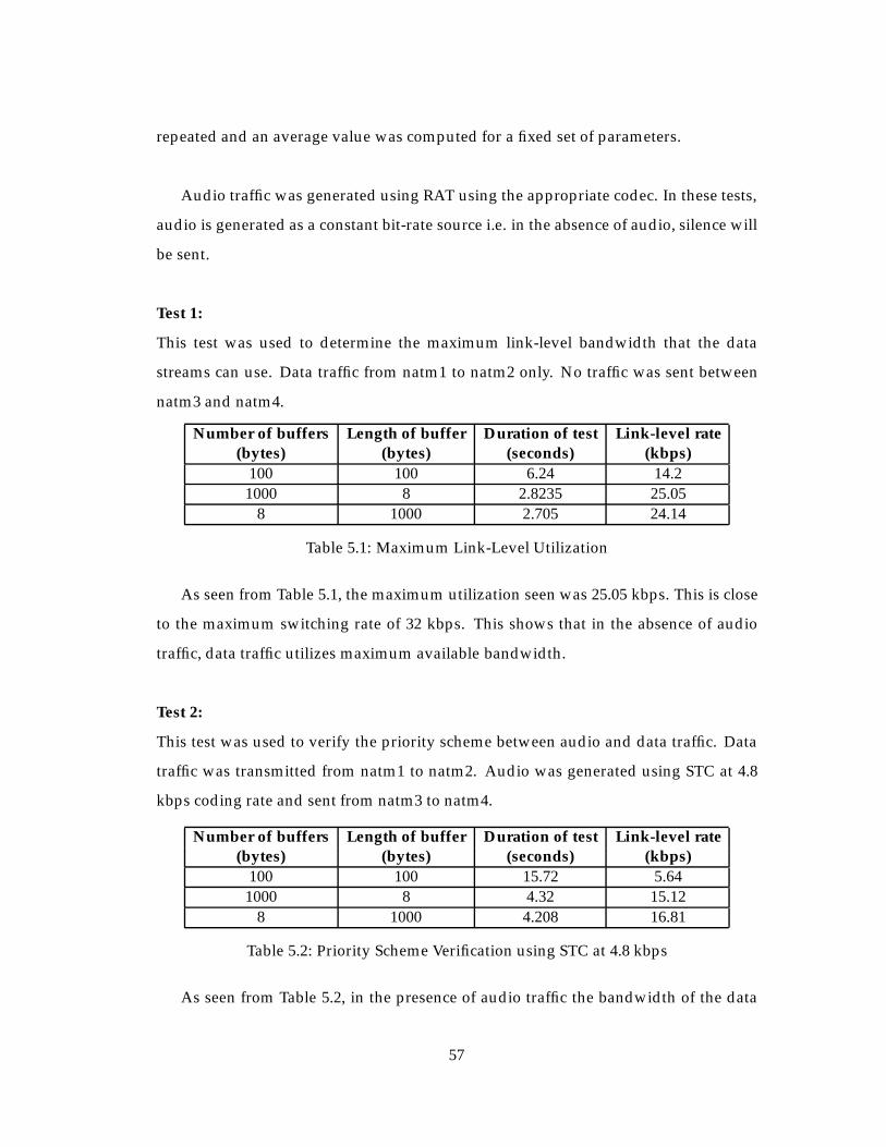
repeated and an average value was computed for a fixed set of parameters.
Audio traffic was generated using RAT using the appropriate codec. In these tests,
audio is generated as a constant bit-rate source i.e. in the absence of audio, silence will
be sent.
Test 1:
This test was used to determine the maximum link-level bandwidth that the data
streams can use. Data traffic from natm1 to natm2 only. No traffic was sent between
natm3 and natm4.
Number of buffers Length of buffer Duration of test Link-level rate(bytes) (bytes) (seconds) (kbps)
100 100 6.24 14.21000 8 2.8235 25.05
8 1000 2.705 24.14
Table 5.1: Maximum Link-Level Utilization
As seen from Table 5.1, the maximum utilization seen was 25.05 kbps. This is close
to the maximum switching rate of 32 kbps. This shows that in the absence of audio
traffic, data traffic utilizes maximum available bandwidth.
Test 2:
This test was used to verify the priority scheme between audio and data traffic. Data
traffic was transmitted from natm1 to natm2. Audio was generated using STC at 4.8
kbps coding rate and sent from natm3 to natm4.
Number of buffers Length of buffer Duration of test Link-level rate(bytes) (bytes) (seconds) (kbps)
100 100 15.72 5.641000 8 4.32 15.12
8 1000 4.208 16.81
Table 5.2: Priority Scheme Verification using STC at 4.8 kbps
As seen from Table 5.2, in the presence of audio traffic the bandwidth of the data
57

traffic reduces. As seen in Table 4.1, the theoretical link-level rate for STC at 4.8 kbps is
13.87 kbps. If this rate is added to the data-traffic rate, the total link rate is nearly the
maximum switching rate possible.
Test 3:
This test was used to verify the priority scheme between audio and data traffic. Data
traffic was transmitted from natm1 to natm2. Audio was generated using STC at 2.4
kbps coding rate with header compression and sent from natm3 to natm4. Also, this
test was used to prove the reduced bandwidth usage of 2.4 kbps STC encoded audio.
Number of buffers Length of buffer Duration of test Link-level rate(bytes) (bytes) (seconds) (kbps)
100 100 6.60 13.421000 8 3.72 17.56
8 1000 3.69 19.17
Table 5.3: Priority Scheme Verification using STC at 2.4 kbps
As seen from Table 5.3, the bandwidth utilized by data traffic in the presence of 2.4
kbps STC encoded audio is more than that seen in Table 5.2. This indicates the lower
bit-rate of the encoded audio traffic.
Test 4:
This test was used to verify the bandwidth sharing between data traffic streams. Data
was transmitted from natm1 to natm2 and simultaneously from natm3 to natm4.
Number of buffers Length of buffer Link-level rate Link-level ratenatm1-natm2 natm3-natm4
(bytes) (bytes) (kbps) (kbps)100 100 7.55 7.951000 8 13.64 11.69
8 1000 15.27 15.31
Table 5.4: Bandwidth Sharing between Data Traffic
As seen from Table 5.4, the sum of the data traffic on the common link is nearly
the same as that in Table 5.1. This shows that bandwidth is shared effectively between
streams of the same traffic.
58

5.3 Active Network
The network topology shown in Figure 5.1 is used for testing the Active Network-
ing functionality too. Active Managers are initiated on all the machines. Depending
on whether the machine is an end-host or a switch it starts the required managers
accordingly e.g. end-hosts will not start the Connection Manager due to its obvious
functionality. It is assumed that before Active Managers come up on end-hosts, all the
user-specific protocols implemented using program code have been loaded in the cor-
rect location. After the Active Manager starts up on the end-hosts, the user is prompted
with a command-line prompt. The user keys in a command which includes the name
of the class of the program code. This results in two things. First, an application in
started on that end-host. In this project, it is the RAT in audiotool mode explained
in section 4.3.1.1 that is started on the end-hosts. Second, the Active Manager sends
the program code out on the PVC socket opened on the unique control VCI (62). The
switch connected at the other end of the link, receives the program code and stores it in
its repository. It then sends the program code on the control VCI PVC of all interfaces
that are enabled on the switch. This results in a cascading effect and the program code
gets installed in the active switches within the network. Since a point-to-point connec-
tion is desired, some other end-host also starts up RAT in audiotool mode using the
command line prompt. A connection is then made between the 2 hosts desiring con-
nection. If an active switch lies in the path of the connection, it executes the program
code associated with the connection from its repository. However, data packets will be
routed to the Active Manager only in case of congestion.
The efficacy of the scheme discussed above was evaluated using STC-coded audio.
The audiotool starts off producing 4.8 kbps coded audio. Two congestion control algo-
rithms were tested. The first one was RAT in bit-dropping mode where the bandwidth
of STC encoded audio was reduced from 4.8 kbps to 2.4 kbps. The second one was
RAT in bit-dropping mode along with header compression to reduce the bandwidth
59
on the congested link. Standard audio clips were sent from the transmitting end-hosts
using RAT. Congestion was simulated on the switches causing active processing to be
performed in the audio data. Audio clips were recorded on the receiving end-hosts.
The performance of the clips using the different congestion algorithms was compared
subjectively.
60

Chapter 6
Summary, Conclusions and Future
Work
6.1 Summary
An Active Network Architecture was proposed and implemented for a Narrowband
ATM Network. The Narrowband ATM network was built using software switches
and end-hosts. The software switches were built using PCs running Linux operating
system and Q-port, the switch call controller. Multiple ports were provided on the
switch using Cyclades multiport card as well as standard ATM OC-3 interfaces. A
software switching driver, the MicroSwitch driver was used as a kernel level applica-
tion to switch cells within the kernel. The end-hosts were standard laptops with serial
ports used for connecting to the Narrowband ATM Network. Standard PCs with OC-3
interface also constitute end-hosts. The physical medium for transmission could be
wireless, wireline or standard telephone lines. A protocol was used which is similar
to the ATM protocol in all aspects except the fixed cell length being 26 bytes with the
header length being 2 bytes. A class-based queuing scheme was designed and imple-
mented within the software switches to allow effective integration of audio and data
traffic, while satisfying the real-time aspect of audio traffic.
The Active Managers for the switches and end-hosts were implemented using the
61

Magician architecture. Additional modules were developed for adapting to ATM net-
works, especially for routing and socket management. Libraries were developed using
Java Native Interface to interface the Active Managers to the switch and end-hosts
kernels. An out-of-band loading scheme was implemented for installing user-defined
protocols on the active switches.
The effectiveness of the architecture was demonstrated using congestion control of
audio streams as the target application. Audio streams coded using Sinusoidal Transfer
Coding were encapsulated using RTP standard within AAL5 packets. Two congestion
control algorithms based on source-independent rate translation were designed and
implemented, the STC Bit-Dropping algorithm and the RTP Header Compression al-
gorithm.
6.2 Conclusions
In this implementation it has been shown that an architecture which allows user-data
to be processed within the switches in ATM networks, increases flexibility in protocol
implementation within the network. Applications are provided the freedom to select
the computation that occurs. This is especially useful in today’s world where inte-
grated traffic is commonplace. Each type of traffic has its own parameters and it is
difficult to provide the a generic scheme to manage traffic. Active Networks allows
customized protocols to be implemented easily. The use of Java language to imple-
ment the Active Network, makes it easy to deploy it on any computing system.
The connection-oriented nature of ATM traffic allows the architecture to be scal-
able, as each interface needs to know only about the interface connected to the other
end of the link. The time required for connection set-up provides an appropriate op-
portunity for pre-installing user protocols on the switches.
62

The applicability of Active Networks has been demonstrated within narrowband
networks by using it for reactive congestion control of audio traffic. Inspite of the ad-
ditional processing performed on the data in the Active Managers on the switches, the
real-time nature of audio traffic was retained. This can be extended to other multime-
dia traffic such as compressing digital video during congestion.
This implementation requires, however, support from the underlying kernels in the
switches. If a standard API is provided by the switch kernels which can give informa-
tion about the switch state, the computation flexibility can be immensely using Active
Networks philosophy on the switch.
6.3 Future Work
The concept of Congestion Control within ATM networks and control within the soft-
ware switch is a huge area in itself. A more complete implementation of the various
Active and Reactive policies possible within the switch should be done and evaluated,
working in tandem with the Active Networking Congestion control.
The Active Network implementation discussed had many ad hoc decisions made to
adapt it to the Narrowband ATM network. Especially where the Active Manager gets
information from the switch about connections etc. The implementation assumes the
network to comprise of software ATM switches alone. A more generic interface needs
to be defined so that Active Managers can reside on any ATM switch.
The effectiveness of Active Networking has been demonstrated for congestion con-
trol using rate-translation. More applications should be developed to prove its capa-
bilities.
It has been shown that the current implementation provides real-time performance.
However, there will be an upper limit on the number of simultaneous connections that
63

it can support while implementing customized protocols on them. This aspect needs to
be investigated and the architecture needs to be optimized to provide a higher thresh-
old for its viability.
An out-of-band approach has been employed for this project for installing program
code using Smart Packets. This was used to avoid latency due to the narrowband net-
work. If the Active Network was deployed over an ATM network with OC-3 links, it
would be interesting to compare the performance with that of an in-band approach.
Also, the SmartPackets may be used not only for installing program code but also for
carrying data packets. Further, the object code itself can be Java byte-code, instead of
system-dependent code. Thus, there may be some significant design changes resulting
from the availability of high-speed links.
The project uses RTP packets embedded with AAL5 packets. AAL5 has an 8-byte
trailer irrespective of the payload size. This overhead can be reduced by using the
trailer bytes to store RTP header bytes which may be compressed [11]. Thus, the over-
all overhead bytes within the packets can be reduced.
The implementation directly uses ATM sockets assuming pure ATM networks. This
is an idealistic view of the network since IP networks exist universally. It will be in-
teresting to see how RTP/IP/AAL5 combination works and how real-time nature of
audio can be maintained considering the increased header overhead.
64

Appendix A
Example of Program Code inserted
by SmartPackets on Active Nodes
/*** Example of program code, sent using SmartPackets to the Active Nodes* in the network. The program code is used to execute system-dependent* object code* KU_SmartPacket_V2_ATM is the base class which is only class accepted by* the execution environment. All code carried by SmartPackets should be* derived from KU_SmartPacket_V2_ATM*/
public class StdStc extends KU_SmartPacket_V2_ATM {
String final_arg;String program_name;String tmp_name;FtpMonitor ftpmonitor;
public void set (String prog, String args, FtpMonitor monitor) {final_arg = args;program_name = "StdStc";ftpmonitor = monitor;
}
/*** The exec() function within the program code will be called by* the Active NodeManager. The contents of this function depends on* the processing that is required by the user data. In this case,* when the ConnectionManager executes the program code, it is* desired that the congestion control program be run for the* particular connection. Hence, as seen below, the object file* is accessed and forked off as a child process.
65

*/
public void exec () {
try {String[] progarray = new String[10];String filePrefix = "/tmp/activenode/obj";objectFileName = filePrefix + program_name;
if (program_name != null) {// Check is current node is an end-host or switch. If end-host,// then exit since algorithm is to be performed on switches,// in this caseFile f1 = new File ("/dev/atmsw");if (!f1.exists()) {
return;}
// Prepare the arguments for the object code executionprogarray[0] = tmp_name;progarray[1] = "-B";progarray[3] = final_arg;
File fobj = new File (tmp_name);// If object code does not exist FTP it from known siteif (!fobj.exists()) {
// Check if FTP is in progress already// Wait if FTP in progress for the object codeif (!ftpmonitor.CheckFtpInProgress()) {
ftpmonitor.SetFtpInProgress();// Perform the FTPftpObj ("obj"+program_name);chmodarray[0]="chmod";chmodarray[1]="777";chmodarray[2]=tmp_name;Process child = Runtime.getRuntime().exec(chmodarray);try {
child.waitFor();} catch (InterruptedException e) {
e.printStackTrace();}ftpmonitor.ResetFtpInProgress();
}} else {
// Wait if FTP is in progressif (!ftpmonitor.CheckFtpInProgress()) {}
}
// Having obtained the object code, pass the appropriate// arguments to it. The object code will perform the
66

// congestion control algorithm on the data passed to// user-space. The control of the child process is maintained// by the ConnectionManagerchild = Runtime.getRuntime().exec(progarray);
}} catch (IOException e) {
System.err.println(e);}
} /* run */
} /* public class StdStc */
67

Bibliography
[1] E. Amir, W. McCanne, and H. Zhang. An application level video gateway. In
ACM Multimedia ’95, 1995.
[2] G. Armitage and K. Adams. Packet reassembly during cell loss. IEEE Network
Magazine, September 1993.
[3] Samrat Bhattacharjee, Kenneth L. Calvert, and Ellen W. Zegura. On Active
Networking and Congestion. Technical Report GIT-CC-96/02, Georgia Institute
of Technology, 1996.
[4] S. Casner and V. Jacobson. Compressing IP/UDP/RTP Headers for Low-Speed
Serial Links. Internet Draft - draft-ieft-avt-crtp-05.txt.
[5] T. G. Champion and J. B. Evans. A flexible multirate speech coder. In Proceedings
of International Conference on Signal Processing Applications and Techniques, pages
1440–1443, September 1993.
[6] C.Kent and J. Mogul. Fragmentation considered harmful. In ACM
SIGCOMM’88, 1988.
[7] The ATM Forum Technical Committee. User-Network Interface (UNI)
Specification. Version 3.1, September 1994.
[8] de Prycker M. Asynchronous Transfer Mode - Solution for Broadband ISDN. Prentice
Hall International, 1995.
[9] Lindsley E. Narrowband ATM Networks. Master’s thesis, University of Kansas,
Lawrence, Kansas, August 1997.
68

[10] David L. Tennenhouse et al. A Survey of Active Network Research. IEEE
Communications Magazine, pages 80–86, January 1997.
[11] Alexander Fraser, Peter Onufryk, and K. K. Ramakrishnan. Encapsulation of
Real-Time Data Including RTP Streams over ATM, February 1998.
[12] Rob Gordon. Essential JNI: Java Native Interface. Prentice Hall Professional
Technical Reference, 1st edition, March 1998.
[13] V. Jacobson. TCP/IP Compression for Low-Speed Serial Links. RFC 1144.
[14] Amit Kulkarni. Magician - An Active Networking Toolkit.
http://ittc.ukans.edu/projects/Magician.
[15] Chen T. M. and Stephen S. L. ATM Switching Systems. Artech House
Incorporated, 1995.
[16] R. J. McAulay and T. F. Quatieri. Multirate sinusoidal transform coding at rate
from 2.4 kbps to 8 kbps. In IEEE Int. Conf. Acoust., Speech, Signal Processing, pages
1645–1648, 1986.
[17] R. J. McAulay and T. F. Quatieri. Speech analysis-synthesis based on a sinusoidal
representation. In IEEE Trans. Acoust., Speech, Signal Processing, pages 744–754,
August 1986.
[18] Vishal Moondhra. Implementation and Performance Analysis of ATM
Adaptation Layer Type 2. Master’s thesis, University of Kansas, Lawrence,
Kansas, January 1998.
[19] David M. Murphy. Building an Active Node on the Internet. Master’s thesis,
Massachusetts Institute of Technology, May 1997.
[20] A. Periyannan. A Reactive Congestion Control Scheme for Gateways in
High-Speed Networks. Master’s thesis, North Carolina State University, Raleigh,
NC, 1992.
69

[21] Bell Communication Research. Q.port Portable Signaling Software:
Implementation Notes. Release 1.3, July 1995.
[22] A. Romanow and S. Floyd. Dynamics of TCP traffic over ATM networks. IEEE
Journal on Selected Areas in Communications, May 1995.
[23] Balaji S. and Raghavan Menon. UTIME - Micro-Second Resoultion Timers for
Linux. http://hegel.ittc.ukans.edu/projects/utime.
[24] H. Schulzrinne, S. Casner, R. Frederick, and V. Jacobson. RTP: A transport
protocol for real-time applications. RFC 1889, January 1996.
[25] David L. Tennenhouse and David J. Wetherall. Towards an Active Network
Architecture. Multimedia Computing and Networking, January 1996.
[26] T. von Eicken et al. Active Message: A mechanism for integrated communication
and computation. In 19th International Symposium on Computer Architecture, 1992.
[27] Almesberger W. Linux ATM internal signaling protocol, Draft Version 0.2,
November 1996.
[28] David J. Wetherall and David L. Tennenhouse. The Active IP Option. In
Proceedings of the 7th ACM SIGOPS European Workshop, September 1996.
70