Embed Size (px)
Citation preview

1
Impacts of Safety on the Design of Light Remotely-Piloted Helicopter Flight Control Systems
G. Di Rito, F. Schettini
Università di Pisa – Dipartimento di Ingegneria Civile ed Industriale – Sez. Aerospaziale, Caruso 8, Pisa, Italy I-56122
Corresponding author: Gianpietro Di Rito, [email protected]
Keywords: light UAS, rotary-wing systems, failure hazard assessment, fault-tree analysis.
ABSTRACT
This paper deals with the architecture definition and the safety assessment of flight control systems
for light remotely-piloted helicopters for civil applications. The methods and tools to be used for
these activities are standardised for conventional piloted aircraft, while they are currently a matter
of discussion in case of light remotely-piloted systems flying into unsegregated airspaces.
Certification concerns are particularly problematic for aerial systems weighing from 20 to 150 kgf,
since the airworthiness permission is granted by national authorities. The lack of specific
requirements actually requires to analyse both the existing standards for military applications and
the certification guidelines for civil systems, up to derive the adequate safety objectives. In this
work, after a survey on applicable certification documents for the safety objectives definition, the
most relevant functional failures of a light remotely-piloted helicopter are identified and analysed
via Functional Hazard Assessment. Different architectures are then compared by means of Fault-
Tree Analysis, highlighting the contributions to the safety level of the main elements of the flight
control system (control computers, servoactuators, antenna) and providing basic guidelines on the
required redundancy level.
1. INTRODUCTION
After the great success in the military sector, there is a worldwide interest in the development of
Unmanned Aerial Systems (UAS’s) for civil and commercial applications. Pipeline inspection,
border control, fire fighting, agricultural management, communications relay, and cargo operations
(i.e. any “dull, dangerous, or dirty” application) seem ideally suited for UAS’s. Nevertheless, the
integration of UAS’s into unsegregated airspaces clearly implies critical safety issues.
2
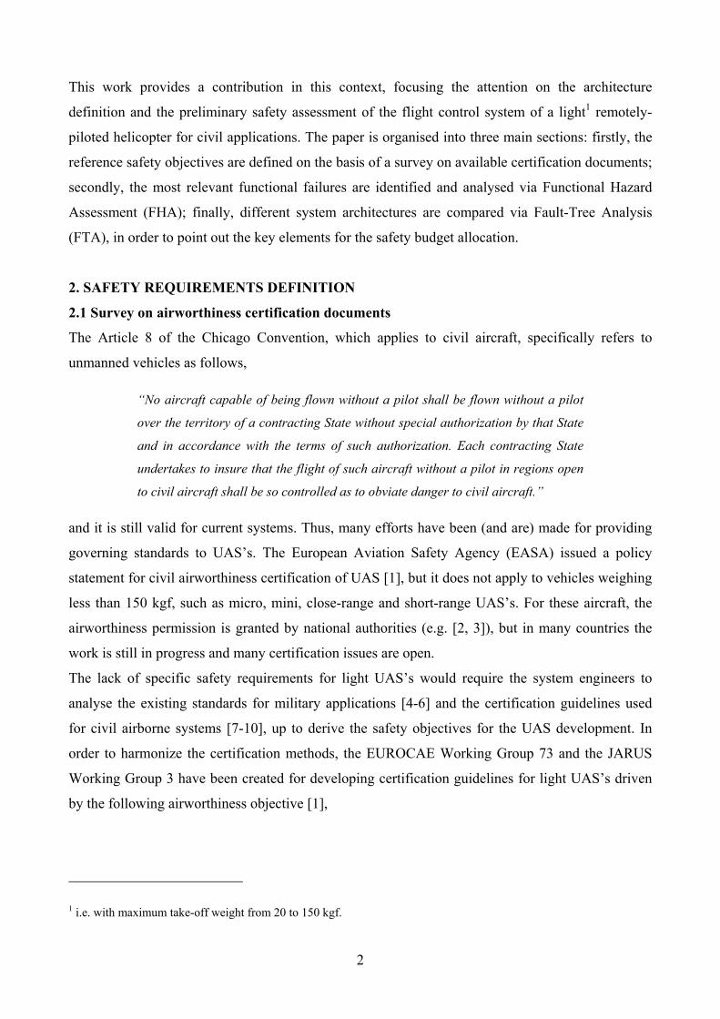
This work provides a contribution in this context, focusing the attention on the architecture
definition and the preliminary safety assessment of the flight control system of a light1 remotely-
piloted helicopter for civil applications. The paper is organised into three main sections: firstly, the
reference safety objectives are defined on the basis of a survey on available certification documents;
secondly, the most relevant functional failures are identified and analysed via Functional Hazard
Assessment (FHA); finally, different system architectures are compared via Fault-Tree Analysis
(FTA), in order to point out the key elements for the safety budget allocation.
2. SAFETY REQUIREMENTS DEFINITION
2.1 Survey on airworthiness certification documents
The Article 8 of the Chicago Convention, which applies to civil aircraft, specifically refers to
unmanned vehicles as follows,
“No aircraft capable of being flown without a pilot shall be flown without a pilot
over the territory of a contracting State without special authorization by that State
and in accordance with the terms of such authorization. Each contracting State
undertakes to insure that the flight of such aircraft without a pilot in regions open
to civil aircraft shall be so controlled as to obviate danger to civil aircraft.”
and it is still valid for current systems. Thus, many efforts have been (and are) made for providing
governing standards to UAS’s. The European Aviation Safety Agency (EASA) issued a policy
statement for civil airworthiness certification of UAS [1], but it does not apply to vehicles weighing
less than 150 kgf, such as micro, mini, close-range and short-range UAS’s. For these aircraft, the
airworthiness permission is granted by national authorities (e.g. [2, 3]), but in many countries the
work is still in progress and many certification issues are open.
The lack of specific safety requirements for light UAS’s would require the system engineers to
analyse the existing standards for military applications [4-6] and the certification guidelines used
for civil airborne systems [7-10], up to derive the safety objectives for the UAS development. In
order to harmonize the certification methods, the EUROCAE Working Group 73 and the JARUS
Working Group 3 have been created for developing certification guidelines for light UAS’s driven
by the following airworthiness objective [1],
1 i.e. with maximum take-off weight from 20 to 150 kgf.
3
“With no persons onboard the aircraft, the airworthiness objective is primarily
targeted at the protection of people and property on the ground. A civil UAS must
not increase the risk to people or property on the ground compared with manned
aircraft of equivalent category […]”
Actually, the safety topic for UAS’s differs from that of conventional aircraft: unlike manned
aircraft, a UAS can be lost without danger for person. For this reason, common methods for the
safety objective definition are based on correlating the catastrophic failure consequences (and the
related safety requirements) to the kinetic energy of the UAS at the impact on ground, also taking
into account the overflown population density [2, 11-16].
2.2 Failure classification and safety requirements
The first step to be accomplished to assess the reliability/safety level for any airborne system is to
define an acceptable probability of occurrence of failure conditions with catastrophic consequences.
In Italy, the airworthiness permission for UAS weighing less than 150 kgf is granted by Ente
Nazionale Aviazione Civile (ENAC), and a draft circular [17] has been issued in 2014 to govern the
initial operations of light UAS’s into Italian civil airspace, and the catastrophic failure probability
for UAS’s flying on unsegregated airspaces is there set to 10-6 fh-1. This safety level implies a
conservative approach, since the catastrophic failure probability for light UAS’s is set to be equal to
the one required for large UAS’s [4], disregarding overflown area population density and kinetic
energy at ground. Nevertheless, this approach is endorsed (and used in this paper) by the authors,
since the spread of civil UAS applications is dramatically growing, and reliability/safety concerns
are expected to be more and more important.
Table 1 has been thus applied to define the relationship between the probability of occurrence and
the severity of failure conditions, and to derive the reliability/safety requirements related to
hazardous, major and minor failures, by following the approach used by the Italian Army for the
certification of light UAS’s flying on unsegregated airspaces [5].
Table 2 finally reports the allocation of software Development Assurance Level (DAL) related to
system and parts recommended in [4], which can be also considered an important reference to
derive similar data for civil applications. It is interesting to note that, in case of redundant systems,
the required software DAL for system parts is one-step lower than that of a non-redundant solution.

4
FAILURE CONSEQUENCES Catastrophic Hazardous Major Minor
PROBABILITY OF OCCURRENCE
Frequent p ≥10‐3 fh‐1 Probable p ≤10‐3 fh‐1 Occasional p ≤10‐4 fh‐1 Remote p ≤10‐5 fh‐1 Improbable p ≤10‐6 fh‐1
Table 1: Relationship between probability and severity of failure conditions.
FAILURE CONSEQUENCES Catastrophic Hazardous Major Minor Single
error Multiple errors (redundant SW)
Single error
Multiple errors (redundant SW)
Single error
Multiple errors (redundant SW)
Single error
Multiple errors (redundant SW)
Part System Part System Part System Part System
DAL E
DAL D
DAL C
DAL B
DAL A
Table 2 – Allocation of SW DAL related to system and parts [4].
3. RW-UAS FCS FUNCTIONAL HAZARD ASSESSMENT
3.1 UAS description
When assessing the safety of a UAS, the analysis must be referred not only to the aerial vehicle, but
to the whole system. In [1], the following definition is given:
“An Unmanned Aircraft System (UAS) comprises individual system elements
consisting of an unmanned aircraft, the control station and any other system
elements necessary to enable flight, i.e. command and control link and launch and
recovery elements […]”
The basic architecture (Figure 1) of the UAS this work refers to is made of:
S1. Air Segment (AS), composed of
S1.1. light Rotary-Wing Unmanned Aerial Vehicle (RW-UAV)
S1.2. Electric Motor
S1.3. Battery Pack
S1.4. Flight Control System, equipped with
• TX/RX system
• Sensor system, including GPS, Sense And Avoid System (SAAS), Inertial
Legend: Unacceptable Acceptable
Legend: Unacceptable Undesirable Acceptable with safety assessment analysis Acceptable without safety assessment analysis

5
Navigation System (INS), Air-Data Sensor (ADS), Ground Sensor (GNDS)
• four flight control servoactuators (SRV), three ones for the main rotor, one
for the tail rotor
• Flight Control Computer (FCC), which elaborates the commands coming
from the GCS and the signals provided by the FCS sensors, implements the
RW-UAS flight control laws, and generates the SRV demands
S2. Ground Segment (GS), i.e. the Ground Control Station (GCS)
S3. Communication Link (CL) between Ground Segment and Air Segment
GroundSensor
Air‐DataSensors
Inertial Navigation System
TX RX
Antenna
RX
TX
Rotary‐wing UAV
SAAS
Figure 1 : Basic architecture of the UAS.
3.2 RW-UAS FCS Functional Hazard Analysis
The safety assessment of the RW-UAS FCS has started from the development of the FHA tables,
which have been referred to the following main RW-UAS functions2 (note that the code used for the
function classification is coherent to the UAS architecture breakdown given at section 3.1):
2 In automatic modes, the RW-UAS flight controls are driven by the FCC, and the GCS pilot provides reference signals
via the inceptors. In autonomous modes, the RW-UAS is capable of implementing missions without receiving
commands by the GCS (e.g. way-point navigation).
6
Servo UAV
ALT/VS sensing
S1.4.f1. Capability to provide means for the GCS pilot to control the UAS via automatic modes
S1.4.f2. Capability to provide means for the GCS pilot to control the UAS via autonomous modes
S1.4.f3. Capability to provide means for the GCS pilot to monitor the UAS FCS health state
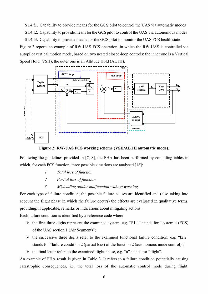
Figure 2 reports an example of RW-UAS FCS operation, in which the RW-UAS is controlled via
autopilot vertical motion mode, based on two nested closed-loop controls: the inner one is a Vertical
Speed Hold (VSH), the outer one is an Altitude Hold (ALTH).
Figure 2: RW-UAS FCS working scheme (VSH/ALTH automatic mode).
Following the guidelines provided in [7, 8], the FHA has been performed by compiling tables in
which, for each FCS function, three possible situations are analysed [18]:
1. Total loss of function
2. Partial loss of function
3. Misleading and/or malfunction without warning
For each type of failure condition, the possible failure causes are identified and (also taking into
account the flight phase in which the failure occurs) the effects are evaluated in qualitative terms,
providing, if applicable, remarks or indications about mitigating actions.
Each failure condition is identified by a reference code where
the first three digits represent the examined system, e.g. “S1.4” stands for “system 4 (FCS)
of the UAS section 1 (Air Segment)”;
the successive three digits refer to the examined functional failure condition, e.g. “f2.2”
stands for “failure condition 2 (partial loss) of the function 2 (autonomous mode control)”;
the final letter refers to the examined flight phase, e.g. “a” stands for “flight”.
An example of FHA result is given in Table 3. It refers to a failure condition potentially causing
catastrophic consequences, i.e. the total loss of the automatic control mode during flight.
Tx/Rx system SRV
system RW‐UAV
ALTH loop VSH loop
Mode switch
GCS
7
Ref. UAS function Phase Failure Condition Failure Effect Classification Remarks / Mitigating Actions
S1.4.f1.1a Provide means for the GCS pilot to control the RW‐UAS via automatic modes
Flight Total loss of the FCS capability to control the RW‐UAS via automatic modes, which can be related to - total loss of FCS capability to
actuate commands - total loss of FCS capability to
sense the state for the automatic mode control
- total loss of the FCS capability to acquire/compute/generate signals
- total loss of the FCS capability to communicate with the GCS
‐ Main rotor swash plate does not move properly ‐ Tail rotor does not move properly ‐ The FCS is unable to control the main rotor thrust ‐ The FCS is unable to control the tail rotor thrust
Catastrophic The failure is unrecoverable and the RW‐UAS impacts to the ground. The effects of the impact on ground can be mitigated by the use of a passive Flight Termination System (e.g. parachute)
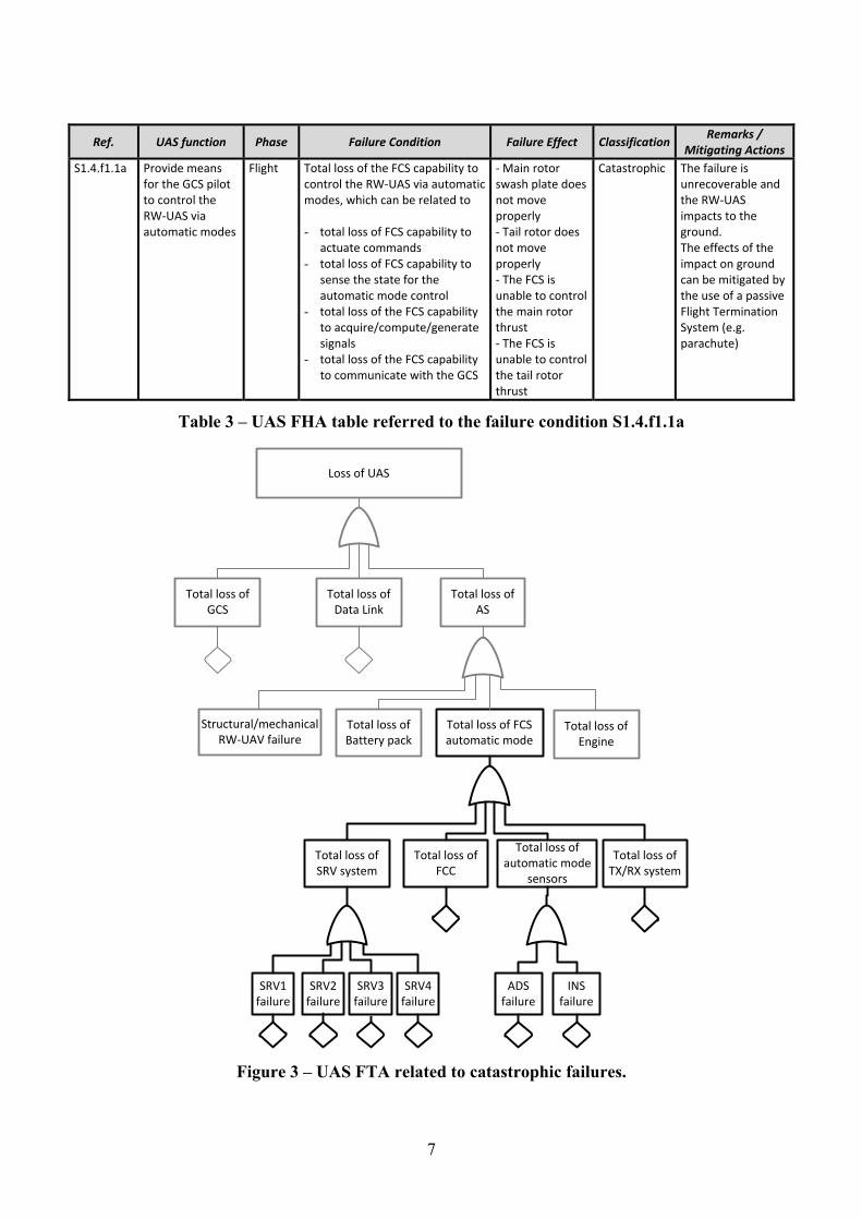
Table 3 – UAS FHA table referred to the failure condition S1.4.f1.1a
Loss of UAS
Total loss of GCS
Total loss of Data Link
Total loss of AS
Total loss of Battery pack
Total loss of FCS automatic mode
Structural/mechanical RW‐UAV failure
Total loss of SRV system
Total loss of FCC
Total loss of automatic mode
sensors
Total loss of TX/RX system
Total loss of Engine
ADS failure
INS failure
SRV1 failure
SRV2 failure
SRV3 failure
SRV4 failure
Figure 3 – UAS FTA related to catastrophic failures.
8
As pointed out in Table 3, the FHA allowed to identify four possible causes bringing to the
S1.4.f1.1a failure condition, related to following failures:
i. total loss of capability to actuate the flight control commands (caused by the SRV system)
ii. total loss of capability to sense the state (caused by the Sensor system)
iii. total loss of capability to implement control computing functions (caused by the FCC)
iv. total loss of capability to communicate with the GCS (caused by the TX/RX system)
The failure condition S1.4.f1.1a is clearly one of the possible situations for the UAS in which
catastrophic consequences occur, as shown in the simplified UAS FTA in Figure 3.
4. COMPARISON OF FCS ARCHITECTURES VIA FAULT-TREE ANALYSIS
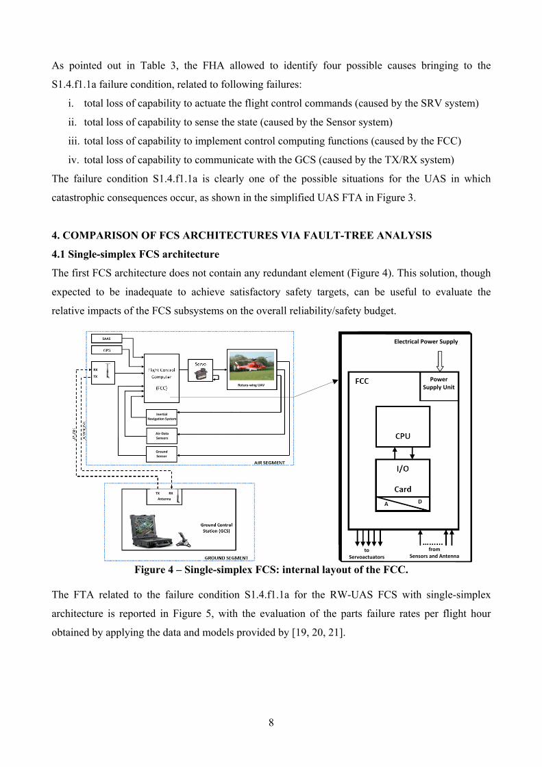
4.1 Single-simplex FCS architecture
The first FCS architecture does not contain any redundant element (Figure 4). This solution, though
expected to be inadequate to achieve satisfactory safety targets, can be useful to evaluate the
relative impacts of the FCS subsystems on the overall reliability/safety budget.
Ground Sensor
Air‐Data Sensors
Inertial Navigation System
TX RX
Antenna
RX
TX
Rotary‐wing UAV
SAAS
from Sensors and Antenna
to Servoactuators
Electrical Power Supply
Power Supply Unit
Figure 4 – Single-simplex FCS: internal layout of the FCC.
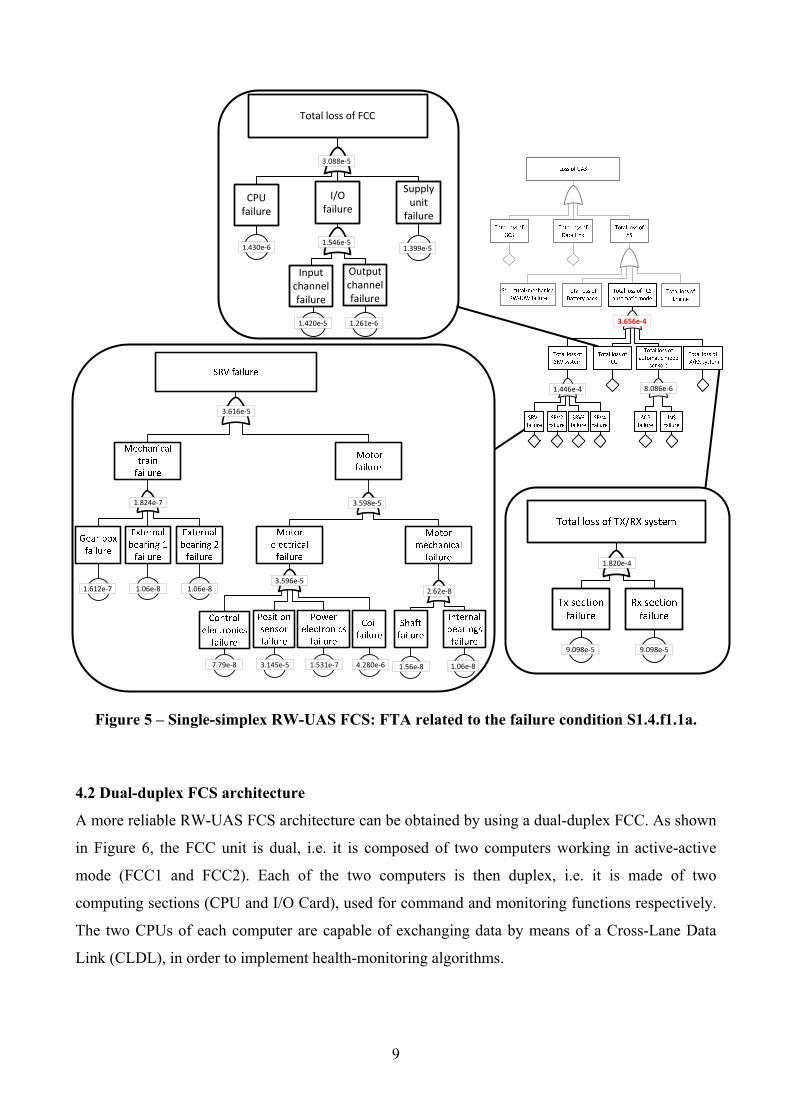
The FTA related to the failure condition S1.4.f1.1a for the RW-UAS FCS with single-simplex
architecture is reported in Figure 5, with the evaluation of the parts failure rates per flight hour
obtained by applying the data and models provided by [19, 20, 21].
9
1.612e‐7 1.06e‐8 1.06e‐8
3.598e‐51.824e‐7
7.79e‐8 3.145e‐5 1.531e‐7 4.280e‐6 1.56e‐8 1.06e‐8
3.596e‐5 2.62e‐8
3.616e‐5
9.098e‐5 9.098e‐5
1.820e‐4
Total loss of FCC
CPUfailure
I/Ofailure
Supply unitfailure
Input channel failure
Output channel failure
1.420e‐5 1.261e‐6
1.546e‐51.430e‐6 1.399e‐5
3.088e‐5
1.446e‐4 8.086e‐6
3.656e‐4
Figure 5 – Single-simplex RW-UAS FCS: FTA related to the failure condition S1.4.f1.1a.
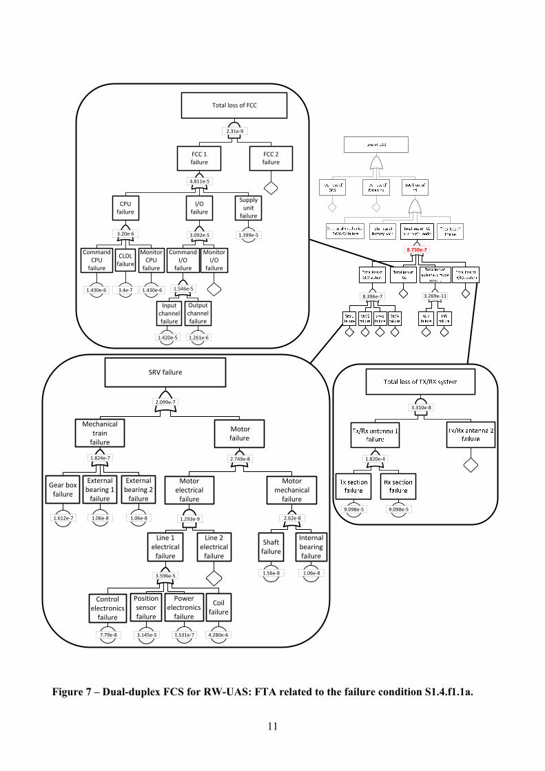
4.2 Dual-duplex FCS architecture
A more reliable RW-UAS FCS architecture can be obtained by using a dual-duplex FCC. As shown
in Figure 6, the FCC unit is dual, i.e. it is composed of two computers working in active-active
mode (FCC1 and FCC2). Each of the two computers is then duplex, i.e. it is made of two
computing sections (CPU and I/O Card), used for command and monitoring functions respectively.
The two CPUs of each computer are capable of exchanging data by means of a Cross-Lane Data
Link (CLDL), in order to implement health-monitoring algorithms.

10
Electrical Power Supply 1
Power Supply Unit 1
Power Supply Unit 2
Electrical Power Supply 2FCC
FCC1 FCC2
I/O Card 1A
(Command)
I/O Card 1B
(Monitor)
I/O Card 2A
(Command)
I/O Card 2B
(Monitor)
CPU 1A
(Command)
CPU 1B
(Monitor)
CLDL 1 CLDL 2
CPU 2A
(Command)
CPU 2B
(Monitor)
from Sensors
and Antenna
to Servoactuators
Figure 6 – Dual-duplex FCS: internal layout of the FCC.
As a result of the dual architectural solution, the servoactuators need to be redundant. Since it is
expected that the integration of multiple actuators in a light RW-UAS could be unfeasible,
intrinsically-redundant SRV are necessary (i.e. the electric motor is equipped with two coils
working in active-active mode).
The FTA related to the failure condition S1.4.f1.1a for the RW-UAS FCS with dual-duplex
architecture is reported in Figure 7, with the evaluation of the parts failure rates per flight hour
obtained by applying the data and models provided by [19, 20, 21].
4.3 Summary of results
The safety analysis results point out that the single-simplex FCS is definitely inadequate for the
required safety target (<10-6 fh-1). It is worth noting that, in this case, the subsystems mainly driving
the safety budget are:
• the FCC, having a failure rate of 3.088 10-5 fh-1
• the SRV system, having a failure rate of 1.446 10-4 fh-1
• the TX/RX system, having a failure rate of 1.82 10-4 fh-1
In particular, the total failure probability of the single-simplex case (3.656 10-4 fh-1) is roughly
given by 39% from the SRV system, by 50% from the TX/RX system, and by the rest by the FCC.
11
8.396e‐7 3.269e‐11
8.750e‐7
Total loss of FCC
FCC 1failure
FCC 2failure
CLDL failure
Command CPU failure
Monitor CPU failure
CPUfailure
I/Ofailure
Supply unitfailure
CommandI/O
failure
Monitor I/O
failure
Input channel failure
Output channel failure
1.420e‐5 1.261e‐6
1.546e‐5 1.430e‐6
1.399e‐5
2.31e‐9
3.092e‐5
1.430e‐63.4e‐7
3.20e‐6
4.811e‐5
SRV failure
Mechanical trainfailure
Motorfailure
Motor electrical failure
Motor mechanical failure
Line 1 electrical failure
Line 2 electrical failure
Control electronics failure
Position sensor failure
Power electronics failure
Coil failure
Gear box failure
External bearing 1 failure
External bearing 2 failure
Shaft failure
Internal bearing failure
1.612e‐7 1.06e‐8 1.06e‐8
1.824e‐7
7.79e‐8 3.145e‐5 1.531e‐7 4.280e‐6
3.596e‐5
1.293e‐9
1.56e‐8 1.06e‐8
2.62e‐8
2.749e‐8
2.099e‐7
9.098e‐5 9.098e‐5
1.820e‐4
3.310e‐8
Figure 7 – Dual-duplex FCS for RW-UAS: FTA related to the failure condition S1.4.f1.1a.
12
On the other hand, the dual-duplex FCS is expected to be compliant, but the margin between the
FTA predictions and the required safety target is quite small (especially if one considers that other
catastrophic failure conditions not involving the FCS must be taken into account, Figure 3).
Moreover, since for the dual-duplex FCS the safety budget is essentially dominated by the
servoactuators, the design of these elements must be followed with great care.
CONCLUSIONS
The work points out that, for the development of a UAS with light RW-UAS, the key safety
elements are the flight control computers, the servoactuators for the flight controls and the TX/RX
system. The number of computers (single or dual), the type of signal processing they implement
(simplex or duplex), as well as the servoactuator technological solution demonstrate to have a
dramatic impact on safety, and they must be regarded as crucial aspects in the development of this
type of UAS. In particular, with reference to a critical failure condition (the total loss of RW-UAS
automatic mode control), a single-simplex FCS is not capable of satisfying the safety requirement
(<10-6 fh-1). The single-simplex FCS failure probability roughly depends for the 50% on the TX/RX
system, for 39% on the servo system, and for the rest on the FCC. The use of a dual-duplex FCS
brings the safety level to be compliant, but the margin between the predictions and the requirement
is quite small. In this perspective, it is important to outline that the safety budget for the dual-duplex
FCS is essentially driven by the servoactuators, so the safety enhancement for this type of UAS
must start from dedicating a great care to the design of these components.
REFERENCES 1. E.Y01301 – Policy Statement Airworthiness Certification of Unmanned Aircraft Systems (UAS), Rulemaking
Directorate, European Aviation Safety Agency (2009).
2. CAP 722 – Unmanned Aircraft System Operations in UK Airspace – Guidance, Directorate of Airspace Policy,
Civil Aviation Authority UK (2009).
3. Ente Nazionale Aviazione Civile, Regolamento - Mezzi Aerei a Pilotaggio Remoto, Edizione n. 2 del 16 luglio 2015
(2015).
4. STANAG 4671 - UAV Systems Airworthiness Requirements (USAR) for North Atlantic Treaty Organization
(NATO) Military UAV Systems, version A (2007).
5. AER(EP).P-6, Istruzioni per la compilazione di capitolati tecnici per aeromobili militari, Ministero della Difesa –
Direzione Generale degli Armamenti Aeronautici 19 (2012).
6. MIL-STD-882D, Standard practice for system safety, US Department of Defense, (2000).
7. SAE ARP 4754 – Certification Considerations for Highly-Integrated or Complex Aircraft Systems, Aerospace
Recommended Practice, Society of Automotive Engineering (1996).
8. SAE ARP 4761 – Guidelines and Methods for Conducting the Safety Assessment Process on Civil Airborne
Systems and Equipments, Aerospace Recommended Practice, Society of Automotive Engineering (1996).
13
9. RTCA DO-178B – Software Considerations in Airborne Systems & Equipment Certification, Radio Technical
Commission for Aeronautics (1992).
10. RTCA DO-254 – Design Assurance Guidelines for Airborne Electronic Hardware, Radio Technical Commission for
Aeronautics (2000).
11. K. Dalamagkidis, K.P. Valavanis; L.A. Piegl, A survey of unmanned aircraft systems regulation: status and future
perspectives, Proceedings of the 16th Mediterranean Conference on Control and Automation, Ajaccio (France), 25-
27 June 2008, p. 717 – 723 (2008).
12. R. Loh, Yi Bian, T. Roe, UAVs in civil airspace: safety requirements, IEEE Aerospace and Electronic Systems
Magazine, Vol. 24 , Issue 1 (2009).
13. European Organisation for Civil Aviation Equipment (EUROCAE) Working Group 73, UAS/RPAS Airworthiness
Certification “1309” System Safety Objectives and Assessment Criteria (2013).
14. Joint Authorities for Rulemaking of Unmanned Systems (JARUS) Working Group 3, Certification Specification for
Light Unmanned Rotorcraft Systems (CS-LURS), Version 1.0 (2013).
15. Working Group JARUS 1309, JARUS Working Paper on UAS System Safety for Airworthiness, UAS-1309_001.2,
(2009).
16. D. R. Haddon, C. J. Whittaker, Aircraft airworthiness certification standards for civil UAVs, Civil Aviation
Authority UK (2002).
17. Ente Nazionale Aviazione Civile, Circolare Bozza - Mezzi aerei a pilotaggio remoto, Serie Navigabilità (2014).
18. K. J. Hayhurst, J. M. Maddalon, P. S. Miner, G. N. Szatkowski, M. L. Ulrey, M. P. DeWalt, and C. R. Spitzer,
Preliminary Considerations for Classifying Hazards of Unmanned Aircraft Systems, National Aeronautics and
Space Administration, Washington, DC (USA), NASA/TM-2007-214539 (2007).
19. MIL-HDBK-217F Notice 2, Reliability Prediction of Electronic Equipment, US Department of Defense, February
28th 1995.
20. NPRD-2011, Non-Electronic Parts Reliability Data 2011, Reliability information Analysis Center (RiAC), US
Department of Defense (RiAC Automated Databook software).
21. ANSI/VITA 51.1 2008 (R2013) Reliability Prediction MIL-HBK 217F Subsidiary Specification, American National
Standards Institute, October 16th 2013.