Embed Size (px)
Citation preview

IEEE
Proo
f
IEEE TRANSACTIONS ON DEVICE AND MATERIALS RELIABILITY, VOL. 8, NO. 2, JUNE 2008 1
Impact of MOSFET Gate-Oxide Reliabilityon CMOS Operational Amplifier in a
130-nm Low-Voltage Process
1
2
3
Ming-Dou Ker, Fellow, IEEE, and Jung-Sheng Chen4
Abstract—The effect of the MOSFET gate-oxide reliability on5operational amplifier is investigated with the two-stage and fold-6ed-cascode structures in a 130-nm low-voltage CMOS process. The7test operation conditions include unity-gain buffer (close-loop)8and comparator (open-loop) configurations under the dc stress,9ac stress with dc offset, and large-signal transition stress. After10overstress, the small-signal parameters, such as small-signal gain,11unity-gain frequency, and phase margin, are measured to verify12the impact of gate-oxide reliability on circuit performances of the13operational amplifier. The gate-oxide reliability in the operational14amplifier can be improved by the stacked configuration under15small-signal input and output application. The impact of soft16and hard gate-oxide breakdowns on operational amplifiers with17two-stage and folded-cascode structures has been analyzed and18discussed. The hard breakdown has more serious impact on the19operational amplifier.20
Index Terms—Analog circuit, dielectric breakdown, gate-oxide21reliability, MOSFETs, operational amplifier.22
I. INTRODUCTION23
THE REDUCTION of power consumption has become24
increasingly important to portable products, such as mo-25
bile phone, notebook, and flash memory. In general, the most26
common and efficient way to reduce the power consumption in27
CMOS very large scale integrated (VLSI) circuits is to reduce28
the power-supply voltage. To reduce the power consumption29
in CMOS VLSI systems, the standard supply voltage trends30
to scale down from 5 to 1 V. Thus, the gate-oxide thickness31
of the MOS transistor will become thin to reduce nominal32
operation voltage (power-supply voltage). In modern CMOS33
VLSI circuits including digital signal processor and embedded34
analog circuitry, the digital circuits are generally implemented35
by using thin-oxide devices. However, analog circuitry needs36
to be operated at a higher supply voltage than the nominal37
supply voltage of thin-oxide devices to achieve a wide dynamic38
range performance or to meet the compatibility requirement39
Manuscript received October 14, 2007; revised January 28, 2008. Thiswork was supported by the National Science Council, Taiwan, R.O.C., underContract NSC 96-2221-E-009-182.
M.-D. Ker is with the Nanoelectronics and Gigascale Systems Labora-tory, Department of Electronics Engineering, National Chiao-Tung University,Hsinchu 300, Taiwan, R.O.C. (e-mail: [email protected]).
J.-S. Chen was with the Nanoelectronics and Gigascale Systems Laboratory,Institute of Electronics, National Chiao-Tung University, Hsinchu 300, Taiwan,R.O.C. He is now with the Power Conversion Taiwan, Fairchild SemiconductorCorporation, Hsinchu 300, Taiwan, R.O.C.
Color versions of one or more of the figures in this paper are available onlineat http://ieeexplore.ieee.org.
Digital Object Identifier 10.1109/TDMR.2008.XXXXXX
with standardized protocols from previous generations [1]. 40
Some design technique to implement the high-voltage tolerance 41
of analog circuits in nanoscale CMOS technology has been 42
reported [1]. In general, the VLSI productions have a lifetime 43
of more than ten years, but the thin gate oxide of the MOS 44
transistor has many problems, such as gate-oxide breakdown, 45
tunneling current, and hot carrier effect, that will degrade the 46
lifetime of the MOS transistor. Therefore, to improve the gate- 47
oxide reliability of MOS transistor and to investigate the effect 48
of gate-oxide breakdown on CMOS circuit performances will 49
become more important in the nanometer CMOS technology. 50
The occurrence of gate-oxide breakdown during the lifetime 51
of CMOS circuits cannot be completely ruled out. The exact ex- 52
trapolation of time to breakdown at circuit operating conditions 53
is still difficult, since the physical mechanism governing the 54
MOSFET gate dielectric breakdown is not yet fully modeled. 55
It was less of a problem for old CMOS technologies, which 56
have the thick gate oxide. However, because the probability of 57
gate-oxide reliability strongly increases with the decrease of 58
gate-oxide thickness [2], [3], the CMOS circuits in nanoscale 59
technologies could be insufficiently reliable. 60
The defect generation leading to gate-oxide breakdown and 61
the nature of the conduction after gate-oxide breakdown have 62
been investigated [2]–[12], which point out that the gate-oxide 63
breakdown will degrade the small-signal parameters of the 64
MOS transistor, such as tranconductance gm and threshold 65
voltage VTH. Recently, some studies on the impact of MOSFET 66
gate-oxide breakdown on circuits have been reported [4]–[12]. 67
In [4], it was demonstrated that the digital complementary logic 68
circuits would remain functional beyond the first gate-oxide 69
hard breakdown. A soft gate-oxide breakdown event in the 70
CMOS digital dynamic logic circuits relying on the uncorrected 71
soft nodes may result in the failure of the circuit [5]. The gate- 72
oxide breakdown on RF circuits was also studied [6]. The im- 73
pact of gate-oxide breakdown on CMOS differential amplifier 74
and digital complementary logic circuits had been simulated 75
[13]. The impact of gate-oxide breakdown on circuit perfor- 76
mances of common-source amplifier had been investigated 77
[14]. Some designs of analog circuits [15], [16] and the mixed- 78
voltage I/O interface [17] indicate that gate-oxide reliability 79
is a very import design consideration in CMOS circuits. The 80
performances of analog circuits strongly depend on the I–V 81
characteristics of MOSFET devices, because the small-signal 82
parameters of MOSFET device are determined by the biasing 83
voltage and current of MOSFET devices. The small-signal gain 84
and frequency response of analog circuits in CMOS processes 85
1530-4388/$25.00 © 2008 IEEE
IEEE
Proo
f
2 IEEE TRANSACTIONS ON DEVICE AND MATERIALS RELIABILITY, VOL. 8, NO. 2, JUNE 2008
are determined by the transconductance gm and output resis-86
tance ro of MOSFET devices. The transconductance gm and87
output resistance ro of MOSFET device can be expressed as88
gm = µCoxW
L(VGS − VTH) =
2ID
(VGS − VTH)(1)
ro =VA
ID(2)
where µ is the mobility of carrier, L denotes the effective89
channel length, W is the effective channel width, Cox is the90
gate-oxide capacitance per unit area, VTH is the threshold91
voltage of MOSFET device, VGS is the gate-to-source voltage92
of MOSFET device, VA is the Early voltage, and the current ID93
is the drain current of MOSFET device. Comparing (1) and (2),94
the drain current ID is the key design factor for analog circuits95
in CMOS process. Therefore, the performances of analog cir-96
cuits in CMOS processes are dominated by the drain currents of97
MOSFET devices. The drain current ID of a MOSFET device98
operated in saturation region can be expressed as99
ID =12µCox
W
L(VGS − VTH)2. (3)
The channel-length modulation and body effect of MOSFET100
devices are not included in (3). The threshold voltage and101
gate-to-source voltage of MOSFET device are the important102
design parameters in (3). However, the gate-oxide overstress of103
MOSFET will cause degradation on the device characteristics104
of MOSFET. Therefore, the gate-oxide breakdown will have105
serious impact on the performances of analog circuits in106
the nanoscale CMOS technology. However, the impact of107
MOSFET gate-oxide breakdown on the CMOS operational108
amplifier circuits is still not well studied and really verified in a109
silicon chip. The CMOS analog circuits are very sensitive to the110
small-signal parameters of MOSFET, such as tranconductance111
gm and threshold voltage VTH. Therefore, the gate-oxide112
breakdown is expected to have severe impact on the circuit113
performances of analog circuits.114
In this paper, the effect of MOSFET gate-oxide reliability on115
the operational amplifiers with the two-stage (nonstacked) and116
folded-cascode (stacked) structures is investigated in a 130-nm117
low-voltage CMOS process [18]. The small-signal gain, phase118
margin, unity-gain frequency, and power supply rejection ratio119
(PSRR) of these operational amplifiers with different configu-120
rations are measured and compared after different stresses.121
II. ANALOG CIRCUITS122
The operational amplifier is a basic unit in many analog123
circuits and systems, such as output buffer, sample-and-hold124
circuit, and analog-to-digital converter. The operational125
amplifiers with the two-stage and folded-cascode structures are126
selected to verify the impact of MOSFET gate-oxide reliability127
on analog circuits. The complete circuits of the operational128
amplifiers are shown in Fig. 1(a) and (b). The operational129
amplifier with the two-stage structure comprises the differential130
amplifier (M1 − M5), common-source amplifier (M6 − M7),131
source follower (M8 − M9), and bias circuit (MB1 − MB4).132
The operational amplifier with the folded-cascode structure 133
comprises the differential amplifier (M10 − M20) and the bias 134
circuit (MB5 − MB13). The operational amplifiers with the 135
two-stage and folded-cascode structures have been fabricated 136
in a 130-nm low-voltage CMOS process. The test dies have 137
been packaged by DIP 40-pin package and measured on a print 138
circuit board (PCB). The normal operating voltage and the 139
gate-oxide thickness (tox) of all MOSFET devices in these 140
operational amplifiers are 1 V and 2.5 nm, respectively. The 141
channel lengths of NMOS and PMOS transistors in the two 142
operational amplifiers are set to 0.5 and 1 µm, respectively, 143
to avoid the short-channel effects such as threshold variation, 144
drain-induced barrier lowering effect, hot-carrier effect, 145
velocity saturation, and mobility degradation effect. The body AQ1146
terminals of all the NMOS and PMOS transistors are connected 147
to ground and power supply voltage, respectively. The device 148
dimensions of two amplifiers are shown in Table I. This design 149
approach is usually used to design the operational amplifier in 150
analog integrated circuit applications. 151
In signal MOSFET device, if the critical terminal voltage 152
of the device, such as gate-to-source voltage (VGS), gate-to- 153
drain voltage (VGD), and drain-to-source voltage (VDS), is kept 154
within the normal operating voltage VDD of the technology, 155
the electric fields across the MOS device will not cause the 156
damage on the gate oxide. Therefore, the bias circuit of the 157
operational amplifiers is designed with a stacked structure to 158
avoid the gate-oxide breakdown. The Miller-compensated ca- 159
pacitance CC of the two-stage operational amplifier in Fig. 1(a) 160
is realized by the metal–insulator–metal structure, which has 161
no gate-oxide reliability problem. The impact of MOSFET 162
gate-oxide reliability on the operational amplifiers with the 163
two-stage and folded-cascode structures is verified by using 164
continuous stress with supply voltage of 2.5 V. The input 165
common-mode voltage of the operational amplifiers is set to 166
1.25 V. Simulated by HSPICE, the open-loop gain and phase 167
margin of the operational amplifier with the two-stage structure 168
are 64.7 dB and 47.8, respectively, under output capacitive 169
load of 10 pF. The open-loop gain and phase margin of another 170
operational amplifier with the folded-cascode structure are 171
61.9 dB and 89, respectively, under output capacitive load of 172
10 pF. The open-loop small-signal gain (AV _two−stage) of the 173
operational amplifier with the two-stage structure is given by 174
AV _two−stage(S)
∼= gm1gm6gm8
goxgoygoz
1 − SCC/gm6
(1 − SCL/goz)(goy + gm6SCL)(4)
where the go and gm are the output conductance and transcon- 175
ductance of the corresponding MOSFET in the operational 176
amplifiers. The gox, goy, and goz are equal to go5 + go2, go6 + 177
go7, and go8 + go9, respectively. The open-loop small-signal 178
gain (AV _folded−cascode) of the operational amplifier with the 179
folded-cascode structure is also written as 180
AV _folded−cascode(S) ∼= gm11Ro
1 + SCLRo(5)
Ro =1
go11+go20gm18ro18
+ go14gm16ro16
(6)

IEEE
Proo
f
KER AND CHEN: IMPACT OF MOSFET GATE-OXIDE RELIABILITY ON CMOS OPERATIONAL AMPLIFIER 3
Fig. 1. Complete circuits of the operational amplifiers with the (a) two-stage and (b) folded-cascode circuit structures.
TABLE IDEVICE DIMENSIONS OF OPERATIONAL AMPLIFIERS WITH THE TWO-STAGE OR FOLDED-CASCODE STRUCTURES

IEEE
Proo
f
4 IEEE TRANSACTIONS ON DEVICE AND MATERIALS RELIABILITY, VOL. 8, NO. 2, JUNE 2008
Fig. 2. Unity-gain buffer configuration for operational amplifiers under dcstress to investigate the impact of gate-oxide reliability to circuit performances.
where ro is the output resistance of the corresponding MOSFET181
in the operational amplifiers. The short-channel effect, body182
effect, and parasitic capacitance of MOS transistors in the183
two operational amplifiers are ignored in (4)–(6). The capaci-184
tances CL and CC are the output capacitive load and Miller-185
compensated capacitance, respectively, in the two operational186
amplifiers.187
III. OVERSTRESS TEST188
The operational amplifiers with the close-loop (unity-gain189
buffer) and open-loop (comparator) configurations are selected190
to verify the impact of MOSFET gate-oxide reliability on the191
circuit performances of the operational amplifiers with the two-192
stage and folded-cascode structures in a 130-nm low-voltage193
CMOS process. The small-signal gain, phase margin, output-194
signal swing, PSRR, and rise and fall times of the operational195
amplifiers varied with gate-oxide breakdown will be measured196
and analyzed. Because the MOSFET devices in analog circuits197
usually work in the saturation region, the gate-oxide breakdown198
is more likely to occur as the conventional time-dependent199
dielectric breakdown. High gate-to-source voltage (VGS), gate-200
to-drain voltage (VGD), and drain-to-source voltage (VDS)201
of the MOSFET are used to get a fast and easy-to-observe202
breakdown occurrence for investigating the impact of the gate-203
oxide reliability on the operational amplifiers. The advantages204
of using static stress are the well-defined distributions of the205
voltages on the devices in the operational amplifiers and the206
better understanding of the consequences of this overstress.207
The stress and measurement supply voltage VDD in operational208
amplifier with two-stage and folded-cascode structures are set209
to 2.5 V. After overstress, the small-signal parameters of the210
operational amplifiers with the two-stage and folded-cascode211
structures are reevaluated under the same operation condition.212
The test operation conditions include unity-gain buffer (close-213
loop) and comparator (open-loop) configurations under the214
dc stress, ac stress with dc offset, and large-signal transition215
stress.216
A. Unity-Gain Buffer (DC Stress)217
The operational amplifiers with the two-stage and folded-218
cascode structures under the configuration of the unity-gain219
buffer are continuously tested in this dc stress, as shown220
in Fig. 2. The output node of the operational amplifiers is221
Fig. 3. Fresh frequency responses of the operational amplifiers with the(a) two-stage and (b) folded-cascode structures operating in the unity-gainbuffer.
connected to the inverting input node to form the configuration 222
of a unity-gain buffer. According to the basic negative-feedback 223
theory, the close-loop small-signal gain of the operational am- 224
plifiers with the two-stage and folded-cascode structures under 225
the unity-gain buffer configuration can be expressed as 226
AfV _two−stage(S) =AV _two−stage(S)
1 + AV _two−stage(S)(7)
AfV _folded−cascode(S) =AV _folded−cascode(S)
1 + AV _folded−cascode(S)(8)
where AV _two−stage(S) and AV _folded−cascode(S) are shown 227
in (4) and (5), respectively. The small-signal gain, unity-gain 228
frequency, and phase margin of the operational amplifier with 229
the two-stage structure operating in a unity-gain buffer are 0.48 230
dB, 2.3 MHz, and 168, respectively, under output capacitive 231
load of 10 pF. Those of the operational amplifier with the 232
folded-cascode structure operating in a unity-gain buffer are 233
−0.4 dB, 1 MHz, and 163, respectively, under output capac- 234
itive load of 10 pF. The noninverting node of the operational 235
amplifiers is biased at 1.25 V, the output capacitive load is set to 236
10 pF, and the supply voltage VDD is set to 2.5 V. The measured 237
results of the fresh frequency responses before any stress are 238

IEEE
Proo
f
KER AND CHEN: IMPACT OF MOSFET GATE-OXIDE RELIABILITY ON CMOS OPERATIONAL AMPLIFIER 5
Fig. 4. Dependence of the small-signal gain on the stress time of the opera-tional amplifiers with the two-stage or folded-cascode structures operating inthe unity-gain buffer under the dc stress.
Fig. 5. Dependence of the unity-gain frequency on the stress time of theoperational amplifiers with the two-stage or folded-cascode structures operatingin the unity-gain buffer under the dc stress.
shown in Fig. 3(a) and (b), where the operational amplifiers239
operate in the unity-gain buffer.240
During this dc overstress, the small-signal gain, unity-gain241
frequency, phase margin, offset voltage, PSRR, and rise and242
fall times of the operational amplifiers will be measured under243
the unity-gain buffer configuration. When those parameters244
are measured, the input signal of 1.25 V at the noninverting245
node (VIN) is replaced by the ac small signal of 200-mV246
sinusoid signal (peak-to-peak amplitude) with a dc common-247
mode voltage of 1.25 V. The dependence of the small-signal248
gain on the stress time of the operational amplifiers with the249
two-stage or folded-cascode structures operating in the unity-250
gain buffer under the dc stress is shown in Fig. 4. The close-251
loop small-signal gain of the operational amplifiers with the252
two-stage and folded-cascode structures under the dc stress is253
not changed, even though the stress time is up to 4000 min.254
The dependence of the unity-gain frequency on the stress time255
of the operational amplifiers with the two-stage or folded-256
cascode structures operating in the unity-gain buffer under257
the dc stress is shown in Fig. 5. The unity-gain frequency of258
the operational amplifier with the two-stage structure under259
Fig. 6. Dependence of the phase margin on the stress time of the operationalamplifiers with the two-stage or folded-cascode structures operating in theunity-gain buffer under the dc stress.
the dc stress is decreased, but that of the operational amplifier 260
with the folded-cascode structure is not obviously changed 261
under the same stress condition. The impact of MOSFET oxide 262
breakdown on circuit behavior will cause the extra gate leakage, 263
threshold voltage (VTH) shift, and reduced transconductance 264
(gm) to degrade circuit performances. The threshold voltage 265
(VTH) shift of MOSFET will change its I–V characteristic. 266
The oxide breakdowns on different MOSFET devices will have 267
different impacts on the circuit performance under negative 268
feedback configuration. The dependence of the phase margin 269
on the stress time of the operational amplifiers with the two- 270
stage or folded-cascode structures operating in the unity-gain 271
buffer under the dc stress is shown in Fig. 6. The phase margin 272
of the operational amplifier with the two-stage structure under 273
the dc stress is decreased, but that of the operational amplifier 274
with the folded-cascode structure is not obviously changed. The 275
degradation on the small-signal performances in the operational 276
amplifier with the two-stage structure under the dc stress can be 277
explained that the gate-oxide breakdown will degrade the tran- 278
conductance gm and threshold voltage VTH of MOS transistor. 279
In (4), the gm and VTH parameters are the principal factors, 280
which dominate the small-signal gain, pole, and zero of the 281
operational amplifier with the two-stage structure. Therefore, 282
if the gm and VTH parameters are degraded with the stress, the 283
small-signal performances of the operational amplifier with the 284
two-stage structure will be changed under the unity-gain buffer 285
configuration. 286
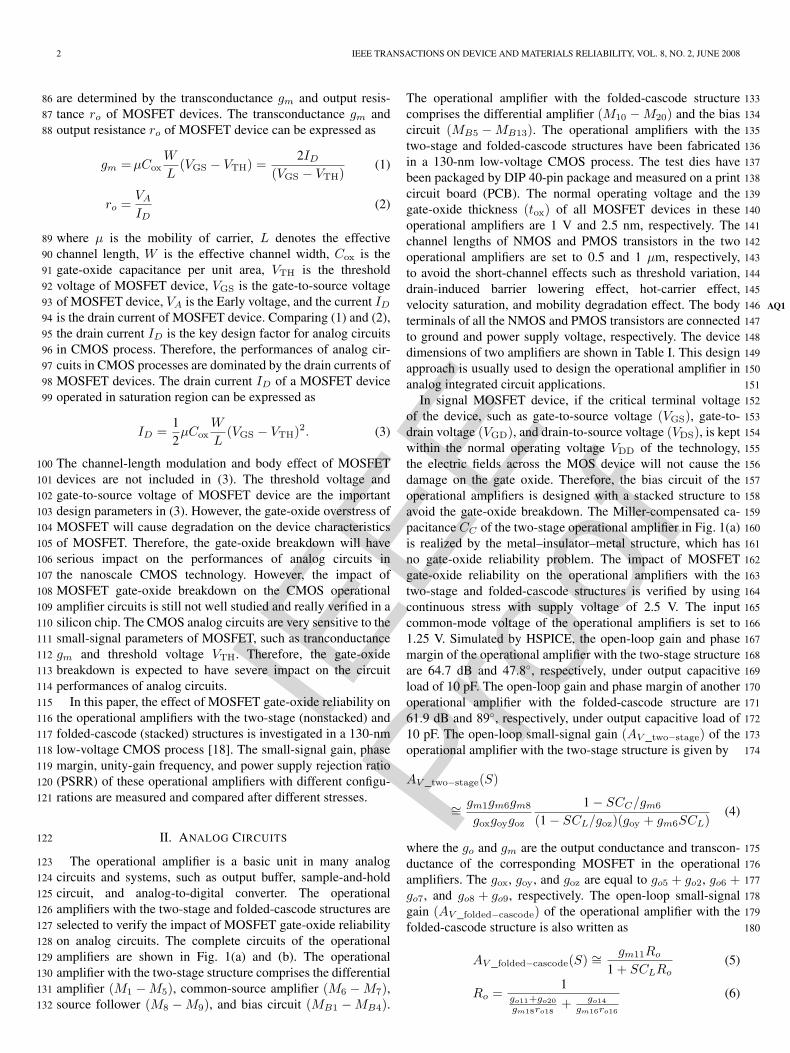
The dependence of the output-voltage swing on the stress 287
time of the operational amplifiers with the two-stage or folded- 288
cascode structures operating in the unity-gain buffer under the 289
dc stress is shown in Fig. 7. The output-voltage swing of the 290
operational amplifier with the two-stage structure under the dc 291
stress is decreased, but that of the operational amplifier with 292
the folded-cascode structure is not changed. The maximum 293
output-signal swing of the operational amplifier with the two- 294
stage structure under the unity-gain buffer configuration can be 295
written as 296
VDS_sat(M8) ≤ Vout ≤ VDD − VDS_sat(M9) (9)
IEEE
Proo
f
6 IEEE TRANSACTIONS ON DEVICE AND MATERIALS RELIABILITY, VOL. 8, NO. 2, JUNE 2008
Fig. 7. Dependence of the output-voltage swing on the stress time of theoperational amplifiers with the two-stage or folded-cascode structures operatingin the unity-gain buffer under the dc stress.
Fig. 8. Dependence of the offset voltage on the stress time of the operationalamplifiers with the two-stage or folded-cascode structures operating in theunity-gain buffer under the dc stress.
where the VDS_sat is the overdrive voltage (VGS − VTH).297
The gate-oxide degradation will degrade the threshold volt-298
age VTH, so the output-signal swing of the operational299
amplifier with the two-stage structure operating in unity-300
gain buffer will be degraded with the overstress under the301
dc stress.302
The input dc offset voltage of operational amplifiers operat-303
ing in the unity-gain buffer can be measured from the voltage304
difference between the inverting and noninverting nodes of the305
operational amplifiers, when the input pin (VIN) is set to a306
common-mode voltage of 1.25 V. The dependence of the input307
dc offset voltage on the stress time of the operational amplifiers308
with the two-stage or folded-cascode structures operating in309
the unity-gain buffer under the dc stress is shown in Fig. 8.310
The offset voltage of the operational amplifier with the two-311
stage structure under the dc stress is increased, but that of the312
operational amplifier with the folded-cascode structure is not313
changed. The input dc offset voltage (VOS) of the operational314
amplifier is caused by the MOS device mismatch and finite-gain315
error, which correspond to the VOS1 and VOS2, respectively,316
under the unity-gain buffer configuration. The input dc offset317
voltage of the operational amplifier under the unity-gain buffer 318
configuration can be expressed as 319
VOS = VOS1 + VOS2 (10)
VOS1 =VGS(M1) − VTH(M1)
2
×[
∆(
WL
)(M1,M2)(
WL
)(M1,M2)
+∆
(WL
)(M4,M5)(
WL
)(M4,M5)
]
− ∆VTH(M1,M2) (11)
VOS2 =Vout
AV _two−stage(0). (12)
The dc offset voltage VOS1 is caused by MOS transistor mis- 320
match of differential amplifier. The dc offset voltage VOS2 321
is caused by the finite small-signal gain of the operational 322
amplifier. The dc offset voltage VOS1 plus VOS2 equals the total 323
input dc offset voltage VOS. In this case, only the impact of 324
MOSFET gate-oxide degradation on the offset voltage VOS2 325
will be considered in the operational amplifier with the two- 326
stage structure, because the differential pair of the two-stage 327
operational amplifier is not degraded with the overstress. The 328
impact of MOSFET oxide breakdown on circuit behavior will 329
cause the extra gate leakage, threshold voltage (VTH) shift, 330
and reduced transconductance (gm) to degrade circuit perfor- 331
mances. The oxide breakdowns on different MOSFET devices 332
will cause different impacts on the circuit performance under 333
negative feedback configuration. The dc offset voltage VOS2 334
is inversely proportional to AV _two−stage(0) in (4). However, 335
the AV _two−stage(0) of the operational amplifier with the two- 336
stage structure will be degraded by gate-oxide degradation, so 337
the input dc offset voltage will be degraded with gate-oxide 338
degradation under the dc stress. 339
About the measurement setup for output-signal rise and fall 340
times of the operational amplifiers operating in the unity-gain 341
buffer, the square voltage signal from 1 to 1.5 V is applied to 342
the input pin to measure the rise and fall times of the signal at 343
output pin. The rise and fall times are defined as the times of 344
the output-signal rise and fall edges from 10% to 90%, when 345
the square waveform of input signal has the rise and fall times 346
of 1 ns. The dependence of the rise and fall times on the stress 347
time of the operational amplifiers with the two-stage or folded- 348
cascode structures operating in the unity-gain buffer under the 349
dc stress is shown in Fig. 9(a)–(c). The rise and fall times of 350
the operational amplifier with the two-stage structure under the 351
dc stress are obviously changed, but those of the operational 352
amplifier with the folded-cascode structure are not changed. 353
The rise and fall times of the operational amplifier with the two- 354
stage structure can be expressed as 355
Trise ∼=CL
IDM8(13)
Tfall ∼=CL
IDM9(14)
where the IDM9 and IDM8 are the drain currents of MOS 356
transistors M8 and M9, respectively. The drain current of MOS AQ2357

IEEE
Proo
f
KER AND CHEN: IMPACT OF MOSFET GATE-OXIDE RELIABILITY ON CMOS OPERATIONAL AMPLIFIER 7
Fig. 9. Dependence of the rise and fall times on the stress time of theoperational amplifiers with the two-stage or folded-cascode structures operatingin the unity-gain buffer under the dc stress. (a) and (b) Two-stage operationalamplifier. (c) Folded-cascode operational amplifier.
transistor in the saturation region can be written as358
ID = Kn
(W
L
)(VGS − VTH)2 (15)
where the Kn is the tranconductance of MOS transistor and the359
W/L is the MOS transistor dimension ratio. In the (13) and360
(14), the rise and fall times of the operational amplifier with361
Fig. 10. Dependence of the PSRR on the stress time of the operationalamplifiers with the two-stage or folded-cascode structures operating in theunity-gain buffer under the dc stress.
the two-stage structure are dominated by the drain current of 362
MOS transistor, which is dependent on threshold voltage VTH 363
in (15). The gate-oxide degradation will degrade the threshold 364
voltage VTH of the MOS transistor, so the rise and fall times 365
of the operational amplifier with the two-stage structure will be 366
changed under the dc stress. 367
In the measurement setup for PSRR, a sinusoidal ripple of 368
100 mV is added to the power supply to measure the small- 369
signal gain between the supply voltage and output pin voltage 370
(VOUT). The ac input signal at the power supply pin must 371
include a dc bias that corresponds to the normal power supply 372
voltage (2.5 V), so that the operational amplifiers operating 373
in the unity-gain buffer remain powered up. The dependence 374
of the PSRR on the stress time of the operational amplifiers 375
with the two-stage or folded-cascode structures operating in 376
the unity-gain buffer under the dc stress is shown in Fig. 10. 377
The PSRR of the operational amplifier with the two-stage 378
structure under the dc stress is obviously changed, but that of 379
the operational amplifier with the folded-cascode structure is 380
not changed. The PSRR of the operational amplifier with the 381
two-stage structure under the unity-gain buffer configuration 382
can be simply expressed as 383
PSRR =VoutVDD
∼= roM8
roM8 + roM9(16)
ro =VA
ID(17)
where the VA is the early voltage of the MOS transistor. The 384
small-signal output resistance depends on the drain current in 385
the MOS transistor. Therefore, the gate-oxide degradation will 386
degrade the PSRR of the operational amplifier with the two- 387
stage structure under the unity-gain buffer configuration during 388
the dc stress. 389
B. Unity-Gain Buffer (AC Stress With DC Offset) 390
The operational amplifiers under the configuration of the 391
unity-gain buffer are continuously tested in the stress of the 392
ac small-signal input with dc offset, as shown in Fig. 11. 393

IEEE
Proo
f
8 IEEE TRANSACTIONS ON DEVICE AND MATERIALS RELIABILITY, VOL. 8, NO. 2, JUNE 2008
Fig. 11. Unity-gain buffer configuration for operational amplifiers under thestress of ac small-signal input with dc offset to investigate the impact of gate-oxide reliability to circuit performances.
Fig. 12. Dependence of the unity-gain frequency on the stress time of theoperational amplifiers with the two-stage or folded-cascode structures underthe stress of the ac small-signal input with dc offset.
The noninverting node of the operational amplifiers with the394
two-stage and folded-cascode structures is biased by the ac395
sinusoidal signal of 500 mV (peak-to-peak amplitude) plus a dc396
offset voltage of 1.25 V with different frequencies of 100 Hz,397
500 kHz, and 1 MHz. The output capacitive load is set to 10 pF,398
and the supply voltage VDD is set to 2.5 V. The measurement399
setup is used to investigate the relationship between gate-oxide400
reliability and different frequencies of input signals in the401
CMOS analog circuit applications.402
The dependence of the unity-gain frequency in the unity-gain403
buffers on the stress time under the stress of the ac small-signal404
input with dc offset is shown in Fig. 12. The performances of405
the operational amplifier with the folded-cascode structure are406
not degraded by the stress of the ac small-signal input with dc407
offset. In the operational amplifier with the two-stage structure,408
the high-frequency input signal causes a slow degradation on409
the unity-gain frequency, but the low-frequency input signal410
causes a fast degradation on the unity-gain frequency under411
the stress of the ac small-signal input with dc offset. The other412
small-signal performances in the operational amplifier with the413
two-stage structure under the stress of the ac small-signal input414
with dc offset have the same change trend as that under the dc415
stress, but the different frequencies of the input signal will cause416
the different degradation times. These measured results are417
consistent to that reported in [11]. The frequency dependence418
of tBD (time to breakdown) is reasonably understood in terms419
Fig. 13. Comparator configuration for operational amplifiers under the stressof large-signal transition to investigate the impact of gate-oxide reliability tocircuit performances.
of the redistribution of the breakdown species from the anodic 420
interface toward the oxide bulk. These two different frequency 421
regimes correspond to two extreme distributions. When the fre- 422
quency is very high, the concentration of “breakdown species” 423
is expected to be low. The distribution strongly peaked at both 424
interfaces. This presumably explains the reduction of degra- 425
dation. On the contrary, in the low frequency, concentration 426
is expected to be high and to have a uniform distribution 427
throughout the oxide film. This leads to the faster degradation 428
process [11]. Therefore, the small-signal performance of the 429
two-stage operational amplifier with different frequencies of the 430
input signals will cause different degradation times under the 431
stress of the ac small-signal input with dc offset. 432
C. Comparator (Large-Signal Transition) 433
The operational amplifiers under the comparator (open-loop) 434
configuration are used to investigate the impact of gate-oxide 435
reliability on CMOS analog circuits under the large-signal 436
transition. The inverting input node of the operational ampli- 437
fiers is biased at 1.25 V, the output capacitance load is set 438
to 10 pF, and the supply voltage VDD is set to 2.5 V. The 439
operational amplifiers under the comparator configuration are 440
continuously tested in this stress of large-signal transition, as 441
shown in Fig. 13. The input square voltage waveform from 1 to 442
1.5 V with frequency of 100 Hz is applied to the noninverting 443
input node of the operational amplifiers under the comparator 444
configuration. The square waveform of input signal from 1 to 445
1.5 V will not induce the damage on the input devices of the 446
operational amplifiers, because the voltages across the input 447
devices (VGS, VGD, and VDS) of the operational amplifiers are 448
lower than the 1 V in this measurement. 449
The dependences of the high- and low-voltage levels at the 450
output node on the stress time are shown in Fig. 14, where 451
the operational amplifiers with the two-stage or folded-cascode 452
structures in the comparator configuration are stressed by 453
the large-signal transition. The low output voltage level of the 454
operational amplifier with the two-stage structure under the 455
stress of large-signal transition is increased when the stress 456
time is increased. However, the high output voltage level of 457
the operational amplifier with the two-stage structure is not 458
changed after the same stress condition. The high and low 459
voltage levels at the output node of the operational amplifier 460
with the folded-cascode structure after the seven-day stress of 461
large-signal transition are not changed. The dependence of the 462

IEEE
Proo
f
KER AND CHEN: IMPACT OF MOSFET GATE-OXIDE RELIABILITY ON CMOS OPERATIONAL AMPLIFIER 9
Fig. 14. Dependences of the high and low voltage levels at the output nodeon the stress time under stress of large-signal transition. The operationalamplifiers with the two-stage or folded-cascode structures are stressed underthe comparator configuration.
Fig. 15. Dependence of the unity-gain frequency on the stress time under thestress of large-signal transition. The operational amplifiers with the two-stageor folded-cascode structures are stressed under the comparator configuration.
unity-gain frequency on the stress time under the stress of large-463
signal transition is shown in Fig. 15, where the operational464
amplifiers with the two-stage or folded-cascode structures are465
connected in the comparator configuration. The unity-gain fre-466
quency of the operational amplifiers with the two-stage and467
folded-cascode structures connected as unity-gain buffer is de-468
graded after the stress of large-signal transition. The reason why469
the circuit performances of the operational amplifiers with the470
two-stage and folded-cascode structures, such as small-signal471
gain and unity-gain frequency, are degraded with the overstress472
is summed up being that the gate-oxide breakdown will degrade473
the transconductance (gm), threshold voltage (VTH), and out-474
put conductance (go) of the MOS transistor. The approximate475
high and low output voltage levels of the operational amplifier476
with the two-stage and folded-cascode structures are near the477
VDD and ground levels, respectively, under the comparator478
configuration. In this case, the VDD level is set to 2.5 V, whereas479
the ground level is set to 0 V. The output-stage devices of the480
operational amplifiers with the two-stage and folded-cascode481
structures will be degraded with gate-oxide degradation, so the482
performances of the operational amplifiers with the two-stage 483
and folded-cascode structures will be degraded under the large- 484
signal transition stress. 485
IV. DISCUSSION 486
The summary of overstress results under three overstress 487
conditions (dc, ac, and large-signal transition stresses) is 488
listed in Table II. The gate-oxide breakdown will degrade the 489
transconductance (gm), output resistance (ro), and threshold 490
voltage (Vth) of MOSFET devices. After the overstress, the per- 491
formances of the two-stage operational amplifiers under close- 492
loop and open-loop configurations are degraded. Because the 493
differential amplifier of the operational amplifier with the two- 494
stage structure consists of three cascode MOSFET devices, the 495
voltages across the devices in the differential amplifier of the 496
operational amplifier with the two-stage structure do not exceed 497
1 V under the stress with the input common-mode voltage of 498
1.25 V and supply voltage of 2.5 V. The differential amplifier 499
of the operational amplifier with the two-stage structure is not 500
degraded under the stresses with the supply voltage of 2.5 V. 501
However, the output stage in the operational amplifier with the 502
two-stage structure will be degraded under the stress with the 503
input common-mode voltage of 1.25 V and supply voltage of 504
2.5 V. Therefore, the open-loop gain of the operational amplifier 505
with the two-stage structure is decreased after the stresses. The 506
offset voltage due to the finite gain error of the operational am- 507
plifier with the two-stage structure is increased after the stress. 508
The rise time, fall time, output voltage swing, and phase 509
margin of the operational amplifier with the two-stage structure 510
are also decreased after the stress. The gate-oxide reliability 511
in the CMOS analog circuits can be improved by the stacked 512
structure. The dc operating point is very important in the 513
analog circuit design, because all small-signal parameters of the 514
devices and circuits are determined by the dc operating point. If 515
the dc operating point is changed after gate-oxide degradation, 516
the analog circuits will not work correctly. However, the large- 517
signal transition at input and output nodes of the operational 518
amplifier with a stacked structure still causes some degradations 519
on circuit performances of analog circuits. As a result, the 520
analog circuits with a stacked structure are only effective to im- 521
prove the gate-oxide reliability under small-signal applications 522
at input and output nodes. 523
Under the same stress condition, the two-stage operational 524
amplifier under close-loop (negative-feedback) configuration 525
can be more easily stressed than that under the open-loop 526
configuration. The close-loop configuration in the operational 527
amplifiers is used to make the circuits stable and to keep the 528
virtual short between inverting and noninverting nodes of the 529
operational amplifiers. Therefore, the inverting, noninverting, 530
and output nodes of the operational amplifiers have the same dc 531
voltage level under the configuration of negative feedback. The 532
transconductance (gm), output resistance (ro), and threshold 533
voltage (VTH) of MOSFET devices will be changed after the 534
stress. In order to make the circuits stable and to keep the 535
virtual short between the two input nodes of the operational 536
amplifier with the two-stage structure, the dc operating point 537
of the output stage in the two-stage operational amplifier will 538

IEEE
Proo
f
10 IEEE TRANSACTIONS ON DEVICE AND MATERIALS RELIABILITY, VOL. 8, NO. 2, JUNE 2008
TABLE IICOMPARISONS OF OPERATIONAL AMPLIFIERS WITH THE TWO-STAGE OR FOLDED-CASCODE STRUCTURES AMONG THREE OVERSTRESS CONDITIONS
Fig. 16. Dependence of power supply current IVDD of the operationalamplifiers with the two-stage or folded-cascode structures on the stress timeunder dc stress.
Fig. 17. Measured output voltage swing waveform of operational amplifierwith the two-stage structure after dc stress.
be changed after the stress. Therefore, the power consumption539
(circuit performances) of the operational amplifier with the two-540
stage structure under the negative-feedback configuration will541
be increased (degraded) after the stress.542
Fig. 18. Complete circuit of the operational amplifier with the two-stagestructure including gate-oxide breakdown model under dc stress.
V. EFFECT OF HARD AND SOFT GATE-OXIDE 543
BREAKDOWNS ON PERFORMANCES 544
OF OPERATIONAL AMPLIFIER 545
A. DC Stress 546
The measured power supply current IVDD of two-stage 547
operational amplifier is jumped from 184 µA to over 300 µA, 548
as shown in Fig. 16, after dc overstress. From such 549
measurement, the oxide breakdown occurred in two-stage 550
operational amplifier can be confirmed after dc overstress. 551
After oxide breakdown, the measured output voltage swing 552
waveform of operational amplifier with the two-stage structure 553
after dc stress, as shown in Fig. 2, is shown in Fig. 17. Based 554
on the prior proposed method [10], the gate-oxide breakdown 555
of MOSFET device can be modeled as resistance. Only the 556
gate-to-diffusion (source or drain) breakdown was considered, 557

IEEE
Proo
f
KER AND CHEN: IMPACT OF MOSFET GATE-OXIDE RELIABILITY ON CMOS OPERATIONAL AMPLIFIER 11
Fig. 19. Simulated output voltage swing waveform of operational amplifier with the two-stage structure under different breakdown resistances RBD6, RBD7,and RBD8.
since these represent the worst case situation. Breakdown558
to the channel can be modeled as a superposition of two559
gate-to-diffusion events. Typical hard breakdown leakage has560
close-to-linear I–V behavior and an equivalent resistance of561
∼103 − 104 Ω, whereas typical soft breakdown paths have high562
nonlinear power law I–V behavior and an equivalent resistance563
above 105 − 106 Ω [10]. The complete circuit of the operational564
amplifier with the two-stage structure, including the gate-oxide565
breakdown model, is shown in Fig. 18. The breakdown566
resistances of RBD6, RBD7, and RBD8 can be used to simulate567
the impact of hard and soft breakdowns on performances of568
the operational amplifier with the two-stage structure. The569
noninverting node of the operational amplifiers with the two-570
stage structure is biased by the ac sinusoidal signal of 500 mV571
(peak-to-peak amplitude) plus dc offset voltage of 1.25 V with572
a frequency of 5 kHz. The output capacitive load is set to 10573
pF, and the supply voltage VDD is set to 2.5 V. The simulated574
output voltage swing waveform of operational amplifier with575
the two-stage structure under different breakdown resistances576
RBD6, RBD7, and RBD8 is shown in Fig. 19. Comparing with577
Fig. 16, the hard breakdowns have occurred on M6, M7, and578
M8 devices in two-stage operational amplifier after dc stress.579
B. Large-Signal Transition Stress580
When the two-stage operational amplifier is operated as581
comparator, the output voltage only has two voltage states.582
One is high output voltage level, and another is low output583
voltage level. In order to investigate and understand the im-584
pact of hard and soft breakdowns on performances of the585
operational amplifier with the two-stage structure under large-586
signal transition stress, the complete circuits including the gate-587
oxide breakdown model are shown in Fig. 20. The simulated588
dependence of high and low output voltage levels of the opera-589
tional amplifier with the two-stage structure under the different590
resistances RBD8 and RBD9 is shown in Fig. 21. Comparing591
Fig. 20. Complete circuit of the operational amplifier with the two-stagestructure including gate-oxide breakdown model under large-signal transientstress.
Figs. 14 and 21, the breakdown locations in the operational 592
amplifier with the two-stage structure occurred on M8 and 593
M9 devices after large-signal transition stress. Because the 594
oxide breakdowns occurred on devices M8 and M9 in two- 595
stage operational amplifier under large-signal transient stress, 596
the node voltages VX and VY would be increased by the extra 597
gate leakage currents IRBD8 and IRBD9. When the voltage of 598
1.5 V is set to input node VIP and the voltage of 1.25 V is set 599
to input node VIN, the node voltage VX approximates to supply 600

IEEE
Proo
f
12 IEEE TRANSACTIONS ON DEVICE AND MATERIALS RELIABILITY, VOL. 8, NO. 2, JUNE 2008
Fig. 21. Simulated high and low output voltage levels of operational amplifier with the two-stage structure under different breakdown resistances RBD8 andRBD9.
voltage VDD. Therefore, the oxide breakdown has small impact601
on the high output voltage level of the two-stage operational602
amplifier under large-signal transient stress. When the voltage603
of 1 V is set to input node VIP and the voltage of 1.25 V604
is set to input node VIN, the node voltage VX approximates605
to ground (0 V) to turn off the device M8. After the large-606
signal transient stress, the node voltages VX and VY would607
be increased by the extra gate leakage currents IRBD8 and608
IRBD9. The device M8 cannot be turned off after the large-609
signal transient stress. Therefore, the low output voltage level610
of the two-stage operational amplifier would be increased after611
the large-signal transient stress.612
VI. CONCLUSION613
The impact of MOSFET gate-oxide reliability on CMOS614
operational amplifiers with the two-stage (nonstacked) and615
folded-cascode (stacked) structures has been investigated and616
analyzed. The tested structures of the operational amplifiers617
including both the unity-gain buffer (close-loop) and compara-618
tor (open-loop) configurations are stressed under different input619
frequencies and signals. Because the dc operating point of the620
analog circuits is changed due to the gate-oxide degradation,621
the small-signal performances of the operational amplifier with622
the two-stage structure are seriously degraded after the stress.623
The performances of the operational amplifier with the two-624
stage structure under the close-loop configuration are damaged625
more easily than that under the open-loop configuration after626
the stress. The gate-oxide reliability in the CMOS analog627
circuits can be improved by the stacked structure under small-628
signal input and output applications. However, the large-signal629
transition still causes some degradation on the circuit perfor-630
mances of the operational amplifier with the folded-cascode631
(stacked) structure. The impact of soft and hard gate-oxide632
breakdowns on operational amplifiers with the two-stage and633
folded-cascode structures has been analyzed and discussed. The 634
hard breakdown has more serious impact on the operational 635
amplifier. 636
REFERENCES 637
[1] D. Seo, H. Dabag, Y. Guo, M. Mishra, and G. H. McAllister, “High- 638voltage-tolerant analog circuits design in deep-submicrometer CMOS 639technologies,” IEEE Trans. Circuits Syst. I, Reg. Papers, vol. 54, no. 10, 640pp. 2159–2166, Oct. 2007. 641
[2] K. Eriguchi and M. Niwa, “Stress polarity dependence of the activation 642energy in time-dependent dielectric breakdown of thin gate oxides,” IEEE 643Electron Device Lett., vol. 19, no. 11, pp. 339–401, Nov. 1998. 644
[3] B. P. Linder, S. Lombardo, J. H. Stathis, A. Vayshenker, and D. Frank, 645“Voltage dependence of hard breakdown growth and the reliability im- 646plication in thin dielectrics,” IEEE Electron Device Lett., vol. 23, no. 11, 647pp. 661–663, Nov. 2002. 648
[4] B. Kaczer, R. Degraeve, M. Rasras, K. V. D. Mieroop, P. J. Roussel, and 649G. Groeseneken, “Impact of MOSFET gate oxide breakdown on digital 650circuit operation and reliability,” IEEE Trans. Electron Devices, vol. 49, 651no. 3, pp. 500–506, Mar. 2002. 652
[5] B. Kaczer and G. Groesenken, “Potential vulnerability of dynamic CMOS 653logic to soft gate oxide breakdown,” IEEE Electron Device Lett., vol. 24, 654no. 12, pp. 742–744, Dec. 2003. 655
[6] H. Yang, J. S. Yuan, Y. Liu, and E. Xiao, “Effect of gate-oxide breakdown 656on RF performance,” IEEE Trans. Device Mater. Rel., vol. 3, no. 3, pp. 93– 65797, Sep. 2003. 658
[7] E. Xiao, J. S. Yuan, and H. Yang, “CMOS RF and DC reliability subject to 659hot carrier stress and oxide soft breakdown,” IEEE Trans. Device Mater. 660Rel., vol. 4, no. 1, pp. 92–98, Mar. 2004. 661
[8] B. E. Weir, P. J. Silverman, D. Monroe, K. S. Krisch, M. A. Alam, G. 662B. Alers, T. W. Sorsch, G. L. Timp, F. Baumann, C. T. Liu, Y. Ma, and 663D. Hwang, “Ultra-thin gate dielectrics: They breakdown, but do they fail,” 664in IEDM Tech. Dig., 1997, pp. 73–76. 665
[9] M. A. Alam, B. E. Weir, P. J. Siverman, Y. Ma, and D. Hwang, “The sta- 666tistical distribution of percolation resistance as a probe into the mechanics 667of ultra-thin oxide breakdown,” in IEDM Tech. Dig., 2000, pp. 529–533. 668
[10] R. Degraeve, B. Kaczer, A. D. Keersgieter, and G. Groeseneken, “Rela- 669tion between breakdown mode and breakdown location in short channel 670NMOSFETs and its impact on reliability specifications,” in Proc. IEEE 671Int. Rel. Phys. Symp., 2001, pp. 360–366. 672
[11] M. Nafria, J. Sune, D. Yelamos, and X. Aymerich, “Degradation 673and breakdown of thin silicon dioxide films under dynamic electrical 674stress,” IEEE Trans. Electron Devices, vol. 43, no. 12, pp. 2215–2226, 675Dec. 1996. 676
IEEE
Proo
f
KER AND CHEN: IMPACT OF MOSFET GATE-OXIDE RELIABILITY ON CMOS OPERATIONAL AMPLIFIER 13
[12] B. Kaczer, F. Crupi, R. Degraeve, P. Roussel, C. Ciofi, and G. Groesenken,677“Observation of hot-carrier-induced nFET gate-oxide breakdown in dy-678namically stress,” in IEDM Tech. Dig., 2002, pp. 171–174.679
[13] A. Aevllan and W. H. Kraustschneider, “Impact of soft and hard break-680down on analog and digital circuits,” IEEE Trans. Device Mater. Rel.,681vol. 4, no. 4, pp. 676–680, Dec. 2004.682
[14] J.-S. Chen and M.-D. Ker, “The impact of gate-oxide breakdown on683common-source amplifiers with diode-connected active load in low-684voltage CMOS processes,” IEEE Trans. Electron Devices, vol. 54, no. 11,685pp. 2860–2870, Nov. 2007.686
[15] A. M. Abo and P. R. Gray, “A 1.5 V, 10-bits, 14.3-MS/s CMOS pipeline687analog-to-digital converter,” IEEE J. Solid-State Circuits, vol. 34, no. 5,688pp. 599–606, May 1999.689
[16] J.-B. Park, S.-M. Yoo, S.-W. Kim, Y.-J. Cho, and S.-H. Lee, “A 10-b 150-690Msample/s 1.8-V 123-mW CMOS A/D converter with 400-MHz input691bandwidth,” IEEE J. Solid-State Circuits, vol. 39, no. 8, pp. 1335–1337,692Aug. 2004.693
[17] B. Serneels, T. Piessens, M. Steyaert, and W. Dehaene, “A high-voltage694output driver in the standard 2.5 V 0.25 µm CMOS technology,” in Proc.695IEEE Int. Solid-State Circuits Conf. Dig. Tech. Papers, 2004, pp. 146–155.696
[18] J.-S. Chen and M.-D. Ker, “Impact of MOSFET gate-oxide reliability in697CMOS operational amplifiers in a 130-nm low-voltage CMOS process,”698in Proc. IEEE Int. Rel. Phys. Symp., 2005, pp. 423–430.699
Ming-Dou Ker (S’92–M’94–SM’97–F’08) received700the Ph.D. degree from the Institute of Electronics,701National Chiao-Tung University, Hsinchu, Taiwan,702R.O.C., in 1993.703
He was a Department Manager with the VLSI704Design Division, Computer and Communication Re-705search Laboratories, Industrial Technology Research706Institute, Taiwan. He is currently a Full Professor707with the Department of Electronics Engineering, Na-708tional Chiao-Tung University, where he also serves709as the Director of Master Degree Program in the710
College of Electrical Engineering and Computer Science as well as the As-711sociate Executive Director of National Science and Technology Program on712System-on-Chip, Taiwan. He is also with the Nanoelectronics and Gigascale713Systems Laboratory, Institute of Electronics, National Chiao-Tung University.AQ3 714In the field of reliability and quality design for circuits and systems in CMOS715technology, he has published over 300 technical papers in international journals716and conferences. He has proposed many inventions to improve reliability and717quality of integrated circuits and microsystems, which have been granted with718129 U.S. patents and 137 Taiwan patents. His current research topics include719reliability and quality design for nanoelectronics and gigascale systems, high-720speed and mixed-voltage I/O interface circuits, on-glass circuits for system-on-721panel applications with TFT technology, and biomimetic circuits and systems722for intelligent prosthesis applications. He had been invited to teach or to consult723reliability and quality design for integrated circuits by hundreds of design724houses and semiconductor companies in the worldwide IC industry.725
Dr. Ker has served as a member of the Technical Program Committee726and Session Chair of numerous international conferences. He was selected727as the Distinguished Lecturer in IEEE Circuits and Systems Society for year7282006–2007. He also served as an Associate Editor in IEEE TRANSACTIONS729ON VLSI SYSTEMS. He was the President of Foundation in Taiwan ESD730Association. In 2003, he was selected as one of the Ten Outstanding Young731Persons in Taiwan by Junior Chamber International. In 2005, one of his patents732on ESD protection design has been awarded with the National Invention Award733in Taiwan. He has been elevated as IEEE fellow, effective in 2008, with the734citation of “for contributions to electrostatic protection in integrated circuits,735and performance optimization of VLSI micro-systems.”736
Jung-Sheng Chen received the B.S. degree in 737electronics engineering from the National Taiwan 738University of Science and Technology, Taipei, 739Taiwan, R.O.C., in 2000, the M.S. degree in en- 740gineering and system science from the National 741Tsing-Hua University, Hsinchu, Taiwan, in 2002, and 742the Ph.D. degree from the Institute of Electronics, 743National Chiao-Tung University, Hsinchu, in 2007. 744
He is currently with Power Conversion Taiwan, 745Fairchild Semiconductor Corporation, Hsinchu. His 746current research interests include power management 747
integrated circuits and systems. 748

IEEE
Proo
f
AUTHOR QUERIES
AUTHOR PLEASE ANSWER ALL QUERIES
AQ1 = Please check if this sentence is correct.AQ2 = “M8 and M9” were changed to " M8 and M9". Please check if appropriate.AQ3 = This additional current affiliation (Nanoelectronics and Gigascale Systems Laboratory) of “Ming-
Dou Ker” was taken from the affiliation footnote. Please check if appropriate.
END OF ALL QUERIES