Embed Size (px)
DESCRIPTION
Impact of cellulose fiber organization and novel fiber assembly techniques. Jeffrey M. Catchmark Department of Engineering Science and Mechanics Department of Agricultural and Biological Engineering School of Forest Resources Vivek Verma Department of Engineering Science and Mechanics - PowerPoint PPT Presentation
Citation preview
Center for NanoCellulosics
Impact of cellulose fiber organization and novel fiber
assembly techniquesJeffrey M. Catchmark
Department of Engineering Science and MechanicsDepartment of Agricultural and Biological Engineering
School of Forest ResourcesVivek Verma
Department of Engineering Science and MechanicsNicole R. Brown
School of Forest ResourcesWilliam O. Hancock
Bioengineering
International Conference on Nanotechnology for the Forest Products Industry
June 13-15, 2007

Center for NanoCellulosics
Overview
Background and motivation for studying cellulose assembly.
Impact of mechanical percolation on cellulose nanofiber composite materials.
Finite element modeling of idealized cellulose nanofiber architectures.
Cellulose nanofiber assembly approach using a system of biomolecular motors and microtubule templates.
Summary

Center for NanoCellulosics
J.F.V. Vincent, U.G.K. Wegst / Arthropod Structure & Development 33 (2004) 187–199
Cellulose: One of nature’s best materials
Center for NanoCellulosics
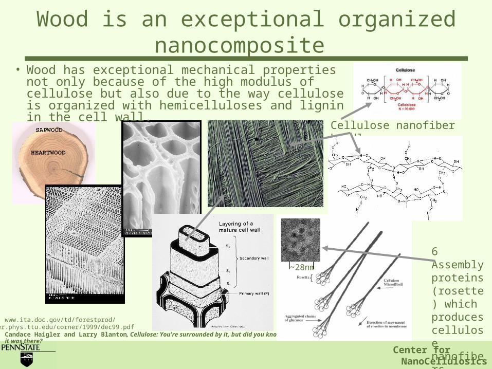
Cellulose nanofiber bundles
6 Assembly proteins (rosette) which produces cellulose nanofibersCandace Haigler and Larry Blanton, Cellulose: You're surrounded by it, but did you know it was there?
jupiter.phys.ttu.edu/corner/1999/dec99.pdf www.ita.doc.gov/td/forestprod/
~28nm
Wood is an exceptional organized nanocomposite
• Wood has exceptional mechanical properties not only because of the high modulus of cellulose but also due to the way cellulose is organized with hemicelluloses and lignin in the cell wall.

Center for NanoCellulosics
Many hard biological tissues, such as tooth (a), vertebral bone (b), or shells (c) are made of nanocomposites with hard mineral platelets in a soft (protein) matrix. (From : Huajian Gao, et. al., PNAS, May 13, 2003, vol. 100, no. 10, 5597–5600.)
Examples of other natural nanocomposites
J.F.V. Vincent, U.G.K. Wegst / Arthropod Structure & Development 33 (2004) 187–199.

Center for NanoCellulosics
J.F.V. Vincent, U.G.K. Wegst / Arthropod Structure & Development 33 (2004) 187–199.
Scanning electron microscope image of the structure of cuttlefish bone. [Taken from: S. Kannan a, J.H.G. Rocha b, S. Agathopoulos c, J.M.F. Ferreira, “Fluorine-substituted hydroxyapatite scaffolds hydrothermally grown from aragonitic cuttlefish bones”Acta Biomaterialia 3 (2007) 243–249.]
Examples of other natural nanocomposites
Center for NanoCellulosics
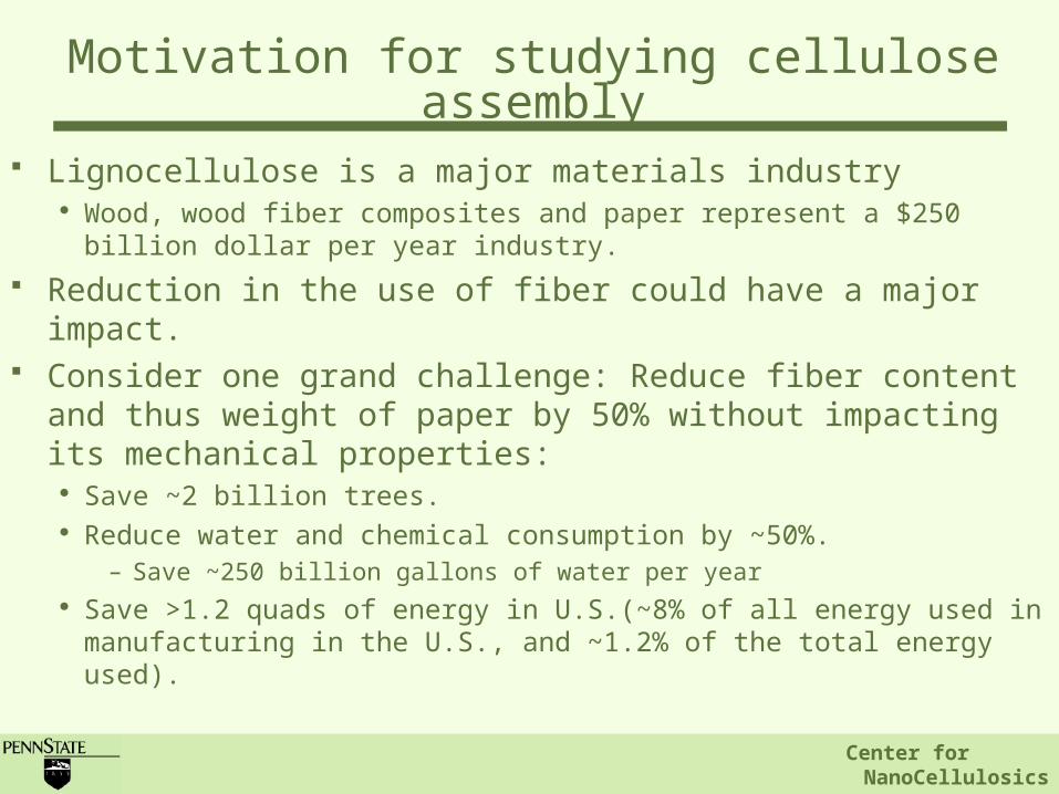
Lignocellulose is a major materials industry Wood, wood fiber composites and paper represent a $250 billion
dollar per year industry. Reduction in the use of fiber could have a major impact. Consider one grand challenge: Reduce fiber content and
thus weight of paper by 50% without impacting its mechanical properties:
Save ~2 billion trees. Reduce water and chemical consumption by ~50%.
– Save ~250 billion gallons of water per year Save >1.2 quads of energy in U.S.(~8% of all energy used in
manufacturing in the U.S., and ~1.2% of the total energy used).
Motivation for studying cellulose assembly
Center for NanoCellulosics
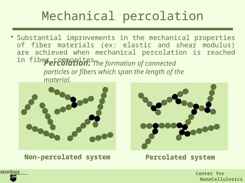
Substantial improvements in the mechanical properties of fiber materials (ex: elastic and shear modulus) are achieved when mechanical percolation is reached in fiber composites.
Non-percolated system Percolated system
Percolation: The formation of connected particles or fibers which span the length of the material.
Mechanical percolation

Center for NanoCellulosics
Plant cell wall Paper
Examples of mechanically percolated materials
Enamel, bone, nacre
Cuttlefish bone

Center for NanoCellulosics
(V. Favier, et. al., Polymer Engineering and Science, Vol. 37, No. 10, 1997).
• Cellulose nanofiber dimensions: 10-20nm diameter - 0.5-5 microns length
• Ecellulose = 150GPa
• Ematrix = 0.5MPa
• Fiber distribution: random.
Finite element mechanical analysis of composites containing nanodimensional
cellulose fiber

Center for NanoCellulosics
Log plot of the measured and calculated shear modulus a function of cellulose fiber volume around the percolation threshold (from V. Favier, et. al., Polymer Engineering and Science, Vol. 37, No. 10, 1997).
Impact of percolation on modulus
Percolation threshold

Center for NanoCellulosics
Log plot of the measured and calculated shear modulus a function of cellulose fiber volume around the percolation threshold (from V. Favier, et. al., Polymer Engineering and Science, Vol. 37, No. 10, 1997).
No control over the relationship between fiber organization and percolation threshold
Impact of percolation on modulus

Center for NanoCellulosics
Engineer fiber organization in cellulose fiber composites to achieve mechanical percolation at lower fiber volumes.
• Produce mechanically similar or improved cellulosic materials using less fiber.
Strategy for improved cellulosic materials

Center for NanoCellulosics
Organized with particles
Random fiber network
All composites contain 144 cellulose nanowhiskers measuring ~2.8 microns by 80 nanometers. Cellulose connections are assumed to be rigid. Cellulose volume – 14.7%All composites assume E=150GPa for the cellulose and E=0.5MPa for the matrix (after previous studied by Favier, et. al.)
Organized composite design assumes E=23GPa for the clay microparticels and E=1GPa for the organic linkers.
Model space measures 14.8m14.8m.
Finite element modeling of cellulose fiber materials
Eeff = 2,790 MPaEeff = 35 MPa
Random with particles
Eeff = 37 MPaEeff = 5,460 MPa
Organized fiber network

Center for NanoCellulosics
Impact of particle and linker on material modulus
0.00
0.50
1.00
1.50
2.00
2.50
3.00
3.50
4.00
4.50
5.00
0.01 0.1 1 10 100
E linker or particle
Eef
f of c
ompo
site
mat
eria
l
Eparticle constant
Elinker constant
Linker modulus very important to final modulus of material
Clay (Kaolinite, 23GPa)
Cellulose (150GPa)
Organic linker (1GPa) 25nm coating on clay particle

Center for NanoCellulosics
Eeff = 7,630 MPa
Contour plot of displacement
All composites contain 144 cellulose nanowhiskers measuring ~2.8 microns by 80 nanometers. Cellulose connections are assumed to be rigid. Cellulose volume – 14.7%All composites assume E=150GPa for the cellulose and E=0.5MPa for the matrix (after previous studied by Favier, et. al.)
Model space measures 14.8m14.8m.
Contour plot of displacement
Eeff = 5,460 MPa
Finite element modeling of cellulose fiber materials
Fiber organization resulting in mechanical percolation at lower fiber volumes has the potential for improving the mechanical properties of cellulosic materials.

Center for NanoCellulosics
Synthesis approach
System of biomolcular motors and microtubule templates:
Diverse network geometries possible. 2D surface geometry which can be modeled using finite
element analysis.
Center for NanoCellulosics
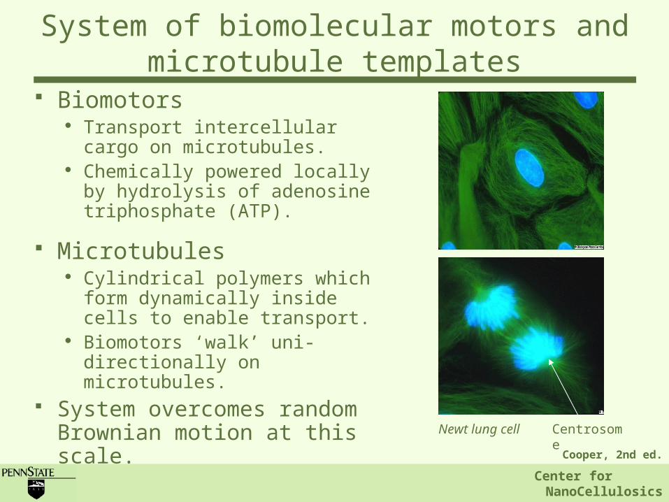
Biomotors Transport intercellular cargo
on microtubules. Chemically powered locally by
hydrolysis of adenosine triphosphate (ATP).
Microtubules Cylindrical polymers which
form dynamically inside cells to enable transport.
Biomotors ‘walk’ uni-directionally on microtubules.
System overcomes random Brownian motion at this scale. Cooper, 2nd ed.
Centrosome
Newt lung cell
System of biomolecular motors and microtubule templates

Center for NanoCellulosics
Biomotors and microtubules are proteins. Many families of biomotor proteins including the kinesin, dynein and myosin.
Microtubules polymerize inside cells via the ordered assembly of and -tub
ulin proteins, which are linked with GTP (guanosine tri-phosphate). Kinesin biomotor head domains connect to the tubulin subunits.
8 nm
25 nm
Kozielski et al.Nogales et al.Cooper, 2nd ed.
7 nm
Plus end
System of biomolecular motors and microtubule templates

Center for NanoCellulosics
Microtubules and biomotors: the ‘nanoarchitects’ of the plant cell wall
Microtubule formation controls the orientation of cellulose fibrils in the plant cell wall. Cellulose producing enzyme rosettes glide between membrane bound microtubules creating aligned fibrils.
Image by Prof. Malcom Brown,
http://www.botany.utexas.edu/facstaff/facpages/mbrown/newstat/stat38.htm
Alexander R. Paredez, Christopher R.
Somerville, David W. Ehrhardt, Science, Vol.
312, 1491, 2006.

Center for NanoCellulosics
In-vitro use of biomotors and microtubules
Glass Substrate
Casein
Microtubule
Kinesin Cargo
Direction of motion
+ End- End
Glass Substrate
+ End- End
Glass Substrate

Center for NanoCellulosics
Self-organizing microtubules: 2D templates for cellulose nanofiber assembly
F. J. Ne´de´lec, T. Surrey, A. C. Maggs & S. Leibler, NATURE, VOL 389, 18, pp. 305-308, 1997
Aster formation at different motor assembly concentrations: a) 25g/ml, b) 37.5g/ml, c) 50 g/ml and d) 15 g/ml.
Multi-head motor assembly containing 4 kinesin linking 2 microtubules.

Center for NanoCellulosics
Streptavidin binds to 4 Biotin
Building motor complexes
Biotinylate motor end group
Image taken from: http://www.arrayit.com/Products/ Substrates/SuperStreptavidin/superstreptavidin.html

Center for NanoCellulosics
Polymerization of Microtubule Asters
• Polymerization of asters to form microtubule templates with varying degrees of percolation.• Microtubule Aster seeds were formed in solution then immobilized on glass surface• Immobilized microtubule asters were polymerized using tubulin under physiological conditions• During polymerization asters grow in length and get interconnected
t = 10 min t = 40 min t = 130 min

Center for NanoCellulosics
Degree of interconnectivity in microtubule templates
• The connectivity of microtubule asters was measured as a function of time.
• The percent connectivity was calculated as the number of asters connected to at least one other aster divided by the total number of asters observed.
• All asters are interconnected forming a fully percolated network at ~130 minutes of microtubule polymerization time.
0
20
40
60
80
100
0 20 40 60 80 100 120 140
Time (min)
Per
cent in
terc
onnec
tivi
ty (%
)
Center for NanoCellulosics
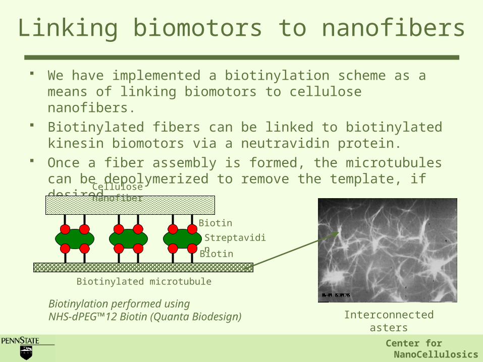
Linking biomotors to nanofibers
We have implemented a biotinylation scheme as a means of linking biomotors to cellulose nanofibers.
Biotinylated fibers can be linked to biotinylated kinesin biomotors via a neutravidin protein.
Once a fiber assembly is formed, the microtubules can be depolymerized to remove the template, if desired.
Cellulose nanofiber
Biotin
Streptavidin
Biotinylated microtubule
Biotin
Interconnected astersBiotinylation performed using NHS-dPEG™12 Biotin (Quanta Biodesign)

Center for NanoCellulosics
Control experiment
Confirming that biotinylated microtubules bind only to cellulose
Biotinylated cellulose immobilized on glass followed by neutravidin and biotinylated microtubules: Microtubules bound on surface
Control 1: No cellulose lead to no microtubule binding on surface
Control 2: Neutravidin absence leads to no microtubule binding to cellulose
Microtubule on cellulose Control 1: No cellulose Control 2: No neutravidin

Center for NanoCellulosics
Assembly of cellulose nanowhiskers over immobilized biotinylated microtubules.
Biotinylated microtubules were immobilized on APTES coated glass. Biotinylated cellulose was bound to the microtubules via biotin-
neutravidin link
Rhodamine labeled microtubules viewed under Rhodamine emission filter (588nm)
Alexa fluor labeled cellulose viewed under Alexa fluor emission filter (647nm)
Linking cellulose to microtubules
Scale bar 20m

Center for NanoCellulosics
Continue with microtubule aster templates and percolated fiber networks formed using functional clay microparticles.
Linking cellulose to microtubules
Finite element model
Interconnected asters
Alexa fluor labeled cellulose viewed under Alexa fluor emission filter

Center for NanoCellulosics
Potential implications for cellulose based materials
Paper:Eeff = 4-15
GPaCellulose fiber volume: ~66%
Organized nanocellulose (theoretical):
Eeff (compressive) = 7.6 GPa
Fiber volume – 14.7%

Center for NanoCellulosics
Other approaches: “Bucky Paper”
Carbon Nanotube “Bucky
paper”
Image taken from Carbon Nanotechnologies Incorporated at http://www.cnanotech.com/pages/resources_and_news/gallery/3-
2_buckytube_gallery.html

Center for NanoCellulosics
Other approaches: “Bucky Paper”
Carbon Nanotube “Bucky
paper”
A little cost prohibitive: >$1,000/sheet

Center for NanoCellulosics
Real need for improved cellulosic materials which incorporate less fiber while maintaining same or superior physical properties.
Organization of cellulose fiber may provide a path toward substantial improvements in the mechanical properties of cellulosic materials and/or substantial reductions in the amount of fiber consumed.
We have demonstrated the ability to produce organized microtubule templates with controllable degrees of mechanical percolation.
We have attached cellulose to the microtubules using a biotin-streptavidin linker.
We are working toward making cellulose composites using these templates and testing their mechanical properties.
Summary

Center for NanoCellulosics
Acknowledgements
Collaborators:– Prof. Nicole Brown, School of
Forest Resources
– Prof. William Hancock, Bioengineering
Student:– Vivek Verma, Ph.D. Student,
Engineering Science and Mechanics

Center for NanoCellulosics
National Science Foundation Materials Research Science and Engineering Center (NSF MRSEC) Center for Nanoscale Science.
Center for NanoCellulosics
Ben Franklin Technology Partners of Central and Northern Pennsylvania
Acknowledgements

Center for NanoCellulosics
Thank you!