Embed Size (px)
Citation preview

w w w . a u t o s t e e l . o r g
Impact Modeling of Spot WeldsIn High-Strength Steels
Dr. Robert YanceyMr. Warren PetersonEdison Welding Institute

w w w . a u t o s t e e l . o r g
020406080
100120140160180200220
0 10 20 30 40 50 60
Engineering Strain (%)
Engi
neer
ing
Stre
ss (k
si)
Stress-Strain Curves
1330 MPa
315 MPa
700 MPa
966 MPa
Stress-Strain Behavior of Steel
Ref: SAE 2000-01-2681

w w w . a u t o s t e e l . o r g
Cross Tension Sample
Ref: SAE 2000-01-2681

w w w . a u t o s t e e l . o r g
Equipment
Drop Weight Impact Tester
Unique Sample DesignSpring
Strikerand
Load Cell
LockingMechanism
Sample
Ref: SAE 2000-01-2681

w w w . a u t o s t e e l . o r g
Steel Strength on Absorbed Energy
Ref: SAE 2000-01-2681

w w w . a u t o s t e e l . o r g
Steel Strength on Peak Load
Ref: SAE 2000-01-2681

w w w . a u t o s t e e l . o r g
Absorbed Energy on Peak Load
Ref: SAE 2000-01-2681
w w w . a u t o s t e e l . o r g
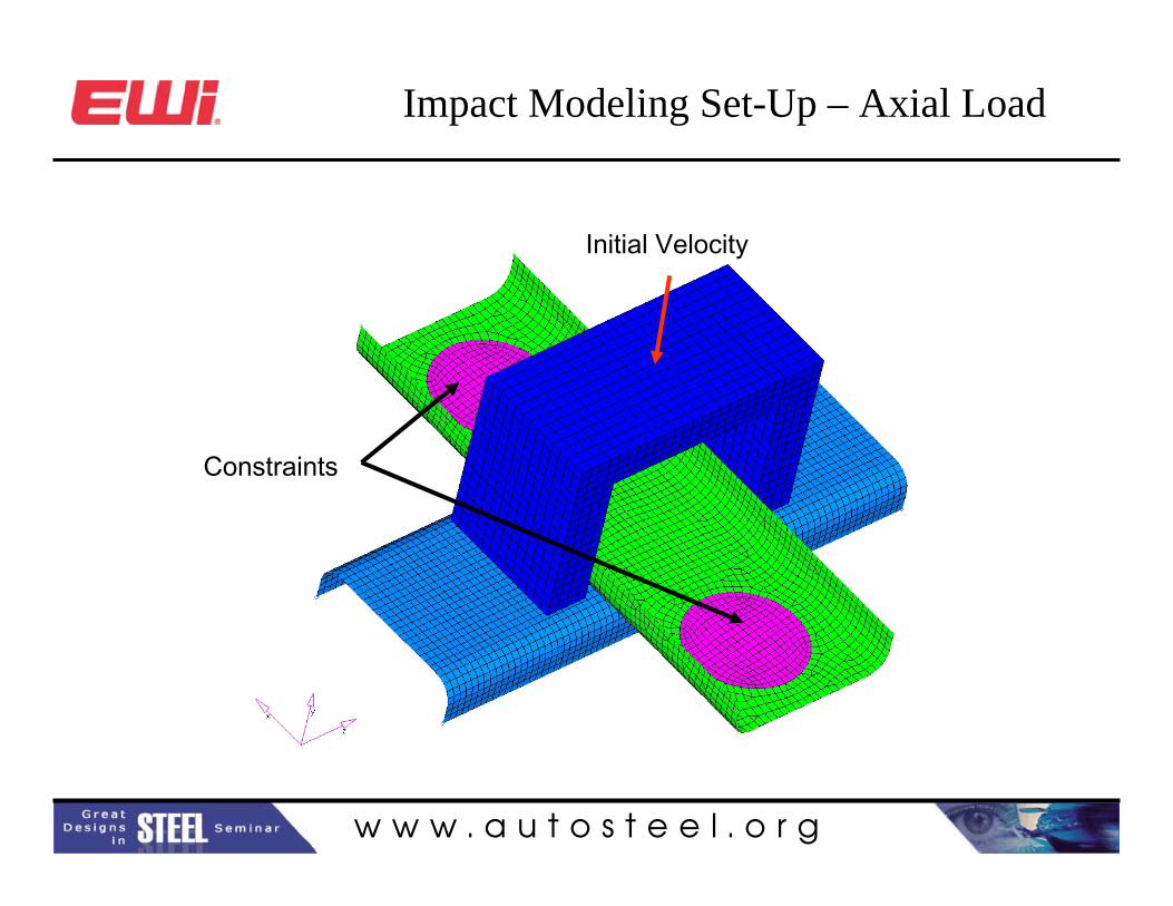
Impact Modeling Set-Up – Axial Load
Constraints
Initial Velocity

w w w . a u t o s t e e l . o r g
Rigid Link Weld
• Standard Weld Connection
• Node to Node• Failure Criteria:
1≥⎟⎟⎠
⎞⎜⎜⎝
⎛+⎟⎟
⎠
⎞⎜⎜⎝
⎛m
s
sn
n
n
Sf
Sf

w w w . a u t o s t e e l . o r g
Effect of Mesh Size – Axial Load
Smaller mesh size Longer Life

w w w . a u t o s t e e l . o r g
Model Deformation - Axial Load

w w w . a u t o s t e e l . o r g
Mesh Independent Welds
• Element to Element
• Contact Definition• Standard Failure
Criteria:
pfp εε ≥

w w w . a u t o s t e e l . o r g
Effect of Mesh Size – Axial Load

w w w . a u t o s t e e l . o r g
Effect of Weld Placement Configuration Axial Load
1
2
3

w w w . a u t o s t e e l . o r g
Model Deformation – Axial Load
w w w . a u t o s t e e l . o r g
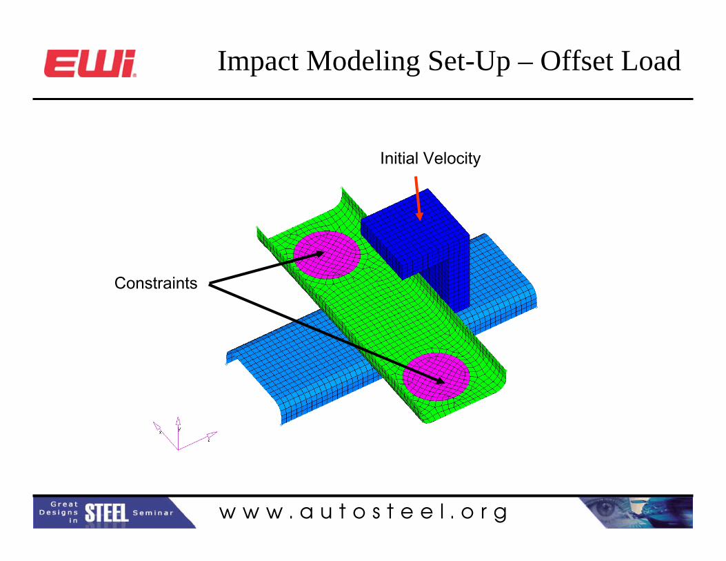
Impact Modeling Set-Up – Offset Load
Constraints
Initial Velocity
w w w . a u t o s t e e l . o r g
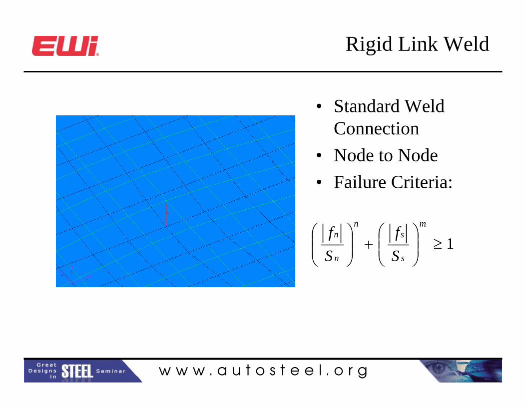
Rigid Link Weld
• Standard Weld Connection
• Node to Node• Failure Criteria:
1≥⎟⎟⎠
⎞⎜⎜⎝
⎛+⎟⎟
⎠
⎞⎜⎜⎝
⎛m
s
sn
n
n
Sf
Sf

w w w . a u t o s t e e l . o r g
Effect of Mesh Size – Offset Load
Smaller mesh size Longer Life

w w w . a u t o s t e e l . o r g
Model Deformation – Offset Load

w w w . a u t o s t e e l . o r g
Mesh Independent Welds
• Element to Element
• Contact Definition• Standard Failure
Criteria:
pfp εε ≥

w w w . a u t o s t e e l . o r g
Effect of Weld Placement Configuration – Offset Load
1
2
3

w w w . a u t o s t e e l . o r g
Effect of Weld Placement Configuration – Offset Load
1
2
3

w w w . a u t o s t e e l . o r g
Model Deformation – Offset Load

w w w . a u t o s t e e l . o r g
Mesh Independent Welds
• Element to Element
• Contact Definition• Failure Criteria:
0122
=−⎟⎠⎞
⎜⎝⎛+⎟
⎠⎞
⎜⎝⎛
FFrr
rr
ττ
σσ

w w w . a u t o s t e e l . o r g
Effect of Weld Placement Configuration – Offset Load
1
2
3

w w w . a u t o s t e e l . o r g
Effect of Weld Placement Configuration – Offset Load
1
2
3

w w w . a u t o s t e e l . o r g
Spot Weld Modeling Conclusions
• Rigid Link Elements are highly mesh dependent
• Mesh Independent Elements are highly dependent on Element location
• Test data is limited
Current Methods are Unreliable

w w w . a u t o s t e e l . o r g
Modeling Vision
0
300
600
900
1200
0 0.05 0.1 0.15 0.2 0.25Total Strain
True
Str
ess
(MPa
)
Location 1 Location 2
Location 3 Location 4
Location 5
Material Properties
Weld Simulation
Structural Analysis