Embed Size (px)
Citation preview

Impact fracturing and structural modification of sedimentary
rocks at Meteor Crater, Arizona
P. Senthil Kumar1,2 and David A. Kring3
Received 18 February 2008; revised 3 June 2008; accepted 22 July 2008; published 23 September 2008.
[1] Meteor Crater provides a rare opportunity to study impact deformation of sedimentarytarget rocks and isolate those features from preexisting tectonic deformation andimpact-generated reactivation of preexisting tectonic features. This study reports over2500 new measurements of orientations of bedding, faults, and fractures in crater wallsand in surrounding bedrock. Target rocks are characterized by horizontal bedding planesthat are cut by at least three prominent sets of preimpact tectonic fracture systems. Thecrater rim is also cut by three distinct groups of fractures: radial, concentric, andconical fractures. When the crater rim is restored to preimpact condition, the radial andconcentric fractures resemble preimpact fracture populations, indicating that craterwall deformation and rim uplift were partly accommodated by activation of preexistingfractures. In contrast, the conical fractures are dissimilar to the preimpact fracturesand apparently formed as a direct result of impact deformation. Some of the preimpactfractures were transformed into tear faults during the impact event, and motion alongthose faults appears to have controlled the geometry of the impact deformational features.The crater rim is, thus, square in plan view rather than circular. Faults occurring in thecrater diagonals are prominent ones, allowing greater vertical displacement. Thedeformation pattern of Meteor Crater is different from that at Lonar Crater, which wasexcavated in basalt with fewer preimpact fractures. The differences between deformationat Meteor Crater and Lonar Crater may reflect the same disparities seen in simple cratersproduced in different target lithologies on Mars and other planetary surfaces.
Citation: Kumar, P. S., and D. A. Kring (2008), Impact fracturing and structural modification of sedimentary rocks at Meteor Crater,
Arizona, J. Geophys. Res., 113, E09009, doi:10.1029/2008JE003115.
1. Introduction
[2] One of the most important characteristics of meteoriteimpact is the deformation of target rocks, which produces anexcavated cavity, uplifted rim, and stratigraphically over-turned ejecta blanket. The deformation occurs in a cata-strophic burst of energy that fractures, melts, and vaporizesmaterial in a few seconds to a few minutes, depending onthe size of the impact event. Deformational stresses are atleast 103 to 104 greater than material strength and strainrates are often 104 to 106/s, which are 7 to 12 orders ofmagnitude greater than that of other geologic processes[Gault et al., 1968; French, 1998]. When an asteroid orcomet hits a planetary surface, a shock wave radiates intothe crust, compressing target lithologies in an expandingsemihemispherical volume of rock. With increasing distancefrom the point of impact the shock wave weakens. Ararefaction or release wave follows the shock wave. The
combined effect of these waves is to create a flow ofmaterial that initially moves downward, then outward andupward, excavating and ejecting material to form the cratercavity. The crater wall represents the limit where the flow isunable to eject material, although wall rock is still upliftedto produce a ring syncline with an axial trace beyond thecrater rim. Furthermore, some of the ejected componentsremain stratigraphically coherent and are structurally over-turned and redeposited on the uplifted crater rim. Deforma-tion is not limited to excavated components, but also occursat greater radial distances from the point of impact whereshock waves permeate the crater walls and surroundingbedrock. Rock is displaced to a depth about 3 times greaterthan the excavated depth, defining a transient crater that ispartially filled with deformed rock, impact breccias, and, inlarge events, impact melt [Dence et al., 1977; Grieve et al.,1977]. Although the energy of the impact event is accom-modated by or dissipated within a large volume of fracturedrock beyond the crater walls, this deformation is still poorlyunderstood.[3] Few simple craters on Earth are sufficiently well
preserved to lend themselves to a structural analysis ofdeformation within crater walls. One of the most interestingexamples is the �220 ka Tswaing impact crater. Formerlyknown as the Pretoria Saltpan crater, this structure is �1 kmin diameter and carved from granite and a thin veneer of
JOURNAL OF GEOPHYSICAL RESEARCH, VOL. 113, E09009, doi:10.1029/2008JE003115, 2008ClickHere
for
FullArticle
1National Geophysical Research Institute, Council of Scientific andIndustrial Research, Hyderabad, India.
2Department of Geological Sciences, Brown University, Providence,Rhode Island, USA.
3Lunar and Planetary Institute, Universities Space Research Associa-tion, Houston, Texas, USA.
Copyright 2008 by the American Geophysical Union.0148-0227/08/2008JE003115$09.00
E09009 1 of 17

Karroo sediments [Partridge, 1999]. Outward directed over-thrusts were measured within the uplifted crater rim andcrosscut by concentric listric faults formed when portions ofthe upper crater wall collapsed downward [Brandt andReimold, 1995, 1999]. In a recent study, one of us [Kumar,2005] examined the �50 ka Lonar Crater, which is �1.8 kmin diameter, but, in this case, carved from basalts of theDeccan Traps. Deformation of crater walls at Lonar wasaccommodated in a series of radial, concentric, and conicalfractures [Kumar, 2005]. Despite these studies, it is not yetclear how impact deformational features might be affectedby preexisting tectonic fractures in a target medium. Nor isit clear if deformation in a sedimentary target sequencemight be significantly different than that in granite andbasalt. To explore both of these issues, we conducted astructural analysis of the bedrock exposed on the walls ofMeteor Crater, which is arguably the world’s best preservedhypervelocity impact crater (Figure 1). It is approximatelysimilar in size to Tswaing and Lonar craters (�1.2 kmdiameter) and similarly young (�50 ka). Previous work[Shoemaker, 1960; Roddy, 1978] demonstrated that thetarget sequence contained at least two sets of preexistingjoints and that these joints may have influenced the finalshape of the crater, which is square in plan view, rather thancircular.[4] We examine the fracturing that occurs in the upper
crater walls and compare them with preimpact tectonicfeatures seen outside the crater, in order to understandhow the preexisting tectonic structures influence the forma-tion of impact structures. Our analysis examines the defor-mation around the entire circumference of the crater.Existing data are sparse and most of them are based onmap measurements rather than field measurements [Roddy,1978]. Furthermore, we compare the impact structures ofMeteor Crater with Lonar Crater for which the detailedstructural geological data are already available [Kumar,2005]. In addition, we consider the results of numericalmodeling studies, laboratory impact experiments, spacecraftcraters, and nuclear explosion craters to better understandthe mechanics of impact deformation. It is worth mention-ing here that the structural framework of Meteor Crater canbe used as an analog to the simple craters of Mars, wheresedimentary rocks are abundant. For example, the craterwall pictures of Endurance Crater taken by Mars Explora-tion Rover Opportunity clearly point to the occurrence offractures on the inner crater wall [Grotzinger et al., 2005],which could probably be related to preimpact tectonicfractures in the target sedimentary rocks [Watters, 2006].
2. Meteor Crater
[5] Meteor Crater (also known as Barringer MeteoriteCrater) was formed as a result of a hypervelocity impact ofan iron asteroid into the Paleozoic-Mesozoic sedimentaryrocks of the southern Colorado Plateau in north centralArizona about 50 ka. For a complete review of the geolog-ical and geophysical aspects of this crater, see Kring [2007].Meteor Crater is a bowl-shaped topographic low (a simpleimpact crater) of �180 m depth and �1200 m diameter(Figure 2). The rim crest rises �30 to �60 m above thesurrounding plains. As seen along the upper crater wall, therim is produced by up to 50 m of impact ejecta and an
uplifted sequence of sedimentary strata. The CoconinoFormation is partly exposed on the present-day middle tolower crater wall; it consists of white, fine-grained, granular,cross-bedded quartzose sandstone (>95% quartz). Thethickness of this sandstone unit varies from 210 to 240 maround the crater. It is overlain by an approximately 3-m-thick Toroweap Formation, which consists of a white toyellowish-brown, medium- to coarse-grained, calcareoussandstone interbedded with thin dolomite beds. It is overlainby �80-m-thick Kaibab Formation, which consists of threemembers: Alpha (yellowish, vuggy, well-bedded dolomiteinterbedded with a few white sandstone beds), Beta (yel-lowish, massive dolomite), and Gamma (white to yellowishmassive dolomite), from the top to bottom, respectively. TheMoenkopi Formation unconformably overlies the KaibabFormation. It consists of two members: a �6-m-thick,upper, Moqui Member (fissile dark brown siltstone) and a3-m-thick, lower, Wupatki Member composed of palereddish-brown, cross-bedded, massive sandstone. Belowthe present-day crater floor, there is a �30-m-thick lens oflake sediments, a �200-m-thick lens of impact breccia andan underlying >750-m-thick sequence of Paleozoic sedi-mentary rocks. Crystalline basement rocks (e.g., granites)occur at a depth of �1070 m from the surface.[6] The ejecta deposits are very well preserved out to a
radial distance >1 km from the crater rim; the blanketconsists of thrown-out debris derived from the rock typesexposed on the inner crater wall. Debris also occurs withinthe crater in the form of complex breccia deposits thatShoemaker [1963] mapped as three units (Figure 2): authi-genic breccia, allogenic breccia, and mixed debris. Theauthigenic breccia is basically the fault gauge materialsthat occur along crater wall faults, whereas the allogenicbreccias are composed of shocked rock fragments andmeteoritic materials, which are well exposed on the middleto lower parts of the western and northern walls. Mixedbreccias are composed of rock fragments derived from thecrater wall and meteorite fragments; these are interpreted tobe fallback ejecta materials.[7] In this study, we present the results of a detailed
structural analysis of the rock exposures far outside thecrater, which are considered to be a proxy of preimpacttarget rocks, and bedrocks on the crater wall that preserveimpact-generated structures. Both outside and inside thecrater we have measured the geometries of the beddingplanes of Moenkopi and Kaibab formations, the fracturesystems, and where ever possible, the geometry of faultsand worked out their kinematics. Over 2500 measurementswere made in June 2007. The strike/dip data have beenimported into digitized equal-area plots (Schmidt net) andevaluated using computer techniques (e.g., RockWorks-2006 software) in order to separate the unique featuresgenerated by the impact event from regional tectonicfeatures [e.g., Kumar, 2005]. In section 3, we present theresults of the structural geological mapping that will allow acomparison of the nature of target rocks before and after theimpact event.
3. Preimpact Structures
[8] Preimpact structures include topography, geometry ofrock formations, and weak zones (e.g., faults and fractures)
E09009 KUMAR AND KRING: IMPACT FRACTURING OF SEDIMENTARY ROCKS
2 of 17
E09009

in them. These preexisting structures can be studied beyondthe region affected by crater formation to determine if theyinfluenced the formation of impact deformational featuresand final crater morphology. A �1070-m-thick horizontallybedded set of Paleozoic to Mesozoic sedimentary strata andunderlying granite-gneiss basement provide the structural
context for Meteor Crater. The sedimentary sequence iscomposed of an �100 m thick Martin Formation, �23-m-thick Redwall Formation, �85-m-thick Naco Formation,�550-m-thick Supai Formation, �220-m-thick CoconinoFormation, �3-m-thick Toroweap Formation, �80-m-thickKaibab Formation and �9-m-thick Moenkopi Formation.
Figure 1. (a) An overlay of the schematic geologic map of the region around Meteor Crater and aColumbia space shuttle image [Kring, 2007]. Anticlinal and synclinal bends and the fault traces havebeen drawn on the basis of the work by Shoemaker [1960]; contacts between the Permian Kaibab (Pk),Triassic Moenkopi (Tm), and Quaternary basalt (Qb) are drawn approximately. (b) An overhead aerialview of Meteor Crater. Rim-to-rim distance is �1.2 km.
E09009 KUMAR AND KRING: IMPACT FRACTURING OF SEDIMENTARY ROCKS
3 of 17
E09009

These formations represent the well-known Grand Canyonsequence. The crater occurs in an area that is variouslycapped by Moenkopi and Kaibab formations (Figure 1). Formore details of the target lithologies, see Kring [2007].[9] Drilling studies that penetrated the ejecta blanket
indicate the preimpact ground surface of Moenkopi wasnearly flat and similar to present-day topography [Roddy etal., 1975]. The rock formations also have near-horizontalbedding planes. However, in some places these rock for-
mations have been affected by gentle folding in the form ofN-S to NNW-SSE oriented very broad open folds (Figure 1).It has also been suggested that the crater was emplaced on ananticlinal axis of a gentle monoclinal fold [Shoemaker,1960]. However, according to Roddy et al. [1975], localdips of the strata are only on the order of a degree or less.Shoemaker [1960] observed two mutually perpendicularsets of preimpact vertical joints of uniform strike (NE-SWand NW-SE). Furthermore, Roddy [1978] reported two
Figure 2
E09009 KUMAR AND KRING: IMPACT FRACTURING OF SEDIMENTARY ROCKS
4 of 17
E09009

more joint systems in the Moenkopi Formation: NNW-SSEand ENE-WSW oriented subvertical joints. All these jointsystems are well preserved in the exposures of Moenkopiand Kaibab formations, and are thought to have beenformed as a result of tectonic deformation affecting theColorado Plateau well before the impact event [e.g.,Kelley and Clinton, 1960]. These joint systems alsocontrol the regional fluvial drainage development of theplateau [Shoemaker, 1963]. In addition to these fracturesystems, faults subparallel to the NNW-SSE to NW-SEoriented fracture systems occur in the area and extend formore than a kilometer. However, according to Roddy [1978],none of these faults occurred at the point of impact and theywere at least 5 km from the point of impact (Figure 1).[10] Although preimpact fracture systems have been
reported previously [Shoemaker, 1960; Roddy, 1978], thedata are sparse and no longer available for analysis. Also,many of the previous data were collected from stereopho-tographic measurements [see Roddy, 1978]. Therefore, wehave collected a new set of data containing the strike/dipmeasurements of the Moenkopi and Kaibab bedding planesand the fractures present in them. The data are presented inFigure 3. Our measurements illustrate that the beddingplanes of sedimentary rocks are nearly horizontal (meandip: 4� ± 1�) (Figure 3), confirming the earlier drillingresults and outcrop measurements. The new measurementsalso reveal a few additional details. We find that themajority of the fractures in the Kaibab Formation areoriented in ENE-WSW direction with subvertical dips. Aspreviously suggested by Shoemaker [1963], these fracturesprobably control the regional drainage patterns aroundthe crater. Interestingly, this dominant fracture set isalso approximately parallel to the ENE-WSW crater walls(Figure 3). Therefore, the data indicate the preexistingfractures do not strictly bisect the crater corners, and mostof them are, indeed, parallel to the crater long walls.
4. Impact-Generated Structures
[11] Impact deformational structures include folds, faults,fractures, and rim uplift that changes the attitude of the rock
formations in and around the crater. Unlike preimpacttectonic structures, these are formed within a few secondsor less. The best place to observe these impact structures ina simple crater are in the bedrocks exposed on the innercrater walls [e.g., Kumar, 2005] and along a cross section ofthe crater rim [e.g., Brandt and Reimold, 1995]. Althoughthe morphology of Meteor Crater has been said to beinfluenced by the preimpact joint systems [Shoemaker,1963], there has been no detailed study that relates howthe preimpact fractures affected the impact deformationalfeatures exposed on the crater wall. The previous studiesapparently lack documentation of impact related joint orfracture systems along the entire crater inner wall. There-fore, we have conducted a structural analysis of the Moquiand Wupatki members of the Moenkopi Formation and theAlpha Member of the Kaibab Formation; these rock for-mations are more or less continuously exposed below theejecta, whereas the underlying rock formations are onlyintermittently exposed on steep slopes where they arelargely covered by talus and alluvium near the present-daycrater floor. Hence, structural mapping was restricted to theupper crater wall. It involved documentation of the geom-etry of bedding planes, various fracture systems, faults andslump units. The inner crater wall can be divided intotwelve angular zones or tectonic blocks (Figure 2) that arebounded by prominent faults with near-vertical, scissors-like faults [e.g., Shoemaker, 1960; Kring, 2007]. Technically,however, they may be better described as high-angle, dip-slip faults. The largest fault occurring in the southeastcorner has generated �45 m of displacement [Shoemakerand Kieffer, 1974]. Structural measurements within theblocks were collected and then compared with adjacentblocks.[12] These measurements reveal radial, concentric, and
conical sets of fractures, which are illustrated in outcropview (Figure 4) and schematically (Figure 5). Figures 6, 7,and 8 show the measured geometries of these radial,concentric, and conical fracture systems in the upper craterwall, respectively. The radial fractures have subvertical dipsand strike approximately perpendicular to the bedding
Figure 2. (a) A simplified geologic map of Meteor Crater based on a map originally prepared by E. M. Shoemaker in1957–1958 and reproduced by Shoemaker and Kieffer [1974]. The crater wall exposes four formations: MoenkopiFormation (MF) that consists of Moqui and Wupatki members (mainly sandstones and siltstones); Kaibab Formation (KF)that consists of Alpha, Beta, and Gamma members (mainly dolomitic limestones); Coconino Formation (CF) (mainlysandstones) overlain by a thin bed of Toroweap Formation containing sandstones. A thin sandstone (SS) marker bed occurswithin the Alpha Member. The ejecta blanket of this crater is very well preserved up to a radial distance of >1 km from thecrater rim. The lower crater wall exposes the following breccia units: allogenic breccia or impact-related breccia withshock-metamorphosed sandstone, labeled IB; authigenic breccia or fault breccia, labeled FB; and mixed breccia or fallbackbreccia, labeled MB. Along the lower crater walls, talus and fine debris cover the allogenic breccia, reducing the steepnessof the crater wall. A �30-m-thick lens of lake sediments covers the allogenic breccia in the crater center, and, along theirperiphery, the lake sediments are interfingered with alluvium that is derived from the crater wall. The crater rim is dividedinto 12 tectonic blocks (labeled with a number from 1 to 12); they are bounded by prominent dip-slip faults (one of which islabeled fault). There are minor faults that do occur within a block, and one of which is labeled F. Thrust faults also occur onthe northern and western crater walls, and one of which is labeled T. Four corners of the crater are cut by major faults (forexample, see the one that is labeled as major fault in the southeast crater corner), which are often called tear faults in theliterature. (b) A panoramic view of the crater wall looking from the ENE to the SSE; an apparent squarish outline of thecrater can be seen. The upper walls have an average slope of �40�–50� but at places are near vertical. Structural geologicalstudies were conducted on the upper wall, where the Moenkopi and Kaibab formations are exposed.
E09009 KUMAR AND KRING: IMPACT FRACTURING OF SEDIMENTARY ROCKS
5 of 17
E09009

Figure 3. Preimpact structures seen far outside the Meteor Crater deformation zone. (a and b) Greatcircles and pole density contours representing the geometry of bedding planes in the Moqui Member ofthe Moenkopi Formation and Alpha Member of the Kaibab Formation; The Wupatki Member is notincluded here because bedding orientations were sometimes difficult to isolate from strong cross-beddedlaminae in the unit. (c) A field photograph showing horizontal bedding surfaces of the Kaibab Formation.(d, e, and f) Great circles, pole density contours, and bidirectional rose diagram showing the orientationof fractures in both Moqui and Wupatki members of the Moenkopi Formation. (g, h, and i) Great circles,pole density contours, and bidirectional rose diagram showing the orientation of fractures in the KaibabFormation, respectively. Equal-area (or Schmidt) net is used to show the great circles and pole densitycontours throughout the paper. Pole density range (in percent) and contour interval (in percent) are showninside the equal-area plots of Figures 3a, 3b, 3e, and 3h; n represents a number of strike/dipmeasurements. Throughout the paper, the strikes are shown with reference to the geographic northconsidering the magnetic declination value of �11� east for June 2007 [National Geophysical DataCenter, 2007].
E09009 KUMAR AND KRING: IMPACT FRACTURING OF SEDIMENTARY ROCKS
6 of 17
E09009

Figure 4. Crater wall pictures showing (a) outward dipping bedding planes of the Kaibab dolomite thatexpose traces of fractures; (b) radial fractures in the Kaibab dolomite; (c) a trace of steeply dippingconcentric fracture in the Moenkopi sandstone showing slumping; and (d) a conical fracture in the Kaibabdolomite cutting the bedding planes.
Figure 5. A schematic diagram showing the crater wall fractures.
E09009 KUMAR AND KRING: IMPACT FRACTURING OF SEDIMENTARY ROCKS
7 of 17
E09009

planes, although some of them are oriented obliquely. Ingeneral, the radial fractures have preferred orientations, inthe directions of NNW-SSE and ENE-WSW, approximatelyparallel to the crater long walls (Figure 6). The radialfractures occur as single, conjugate pairs, and branchingtypes. Most of them are straight to curvilinear on map view.The concentric fractures strike more or less parallel to thebedding planes and dip away from the dip directions of thebedding planes (Figure 7). That is, the concentric fracturesdip toward the center of the crater except where affected bylateral tilting (e.g., drag folding near a tear fault). The
amount of dip of these fractures is also highly variable.The concentric fractures also have preferred orientation inthe direction of the dominant preimpact fractures, i.e.,ENW-ESE, while the other sets are less dominant. Theconical fractures are similar to the concentric fractures intheir strikes, but have highly variable dips that are roughlyin the direction of the bedding planes (Figure 8). Interest-ingly, the conical fractures have a preferred orientation witha NW-SE bearing and a less dominant NE-SW bearing.
Figure 6. Impact structures (radial fractures): great circles, pole density contours, and bidirectional rosediagrams representing the geometry of radial fractures in the Moenkopi (Moqui and Wupatki members)and Kaibab formations (Alpha and Beta members) exposed on the 12 crater wall tectonic blocks. Thepole density range (in percent) and contour interval (in percent) are shown near the equal-area plots; nrepresents a number of strike/dip measurements. A bidirectional rose diagram representing allmeasurements indicates preferential orientations of the radial fractures.
E09009 KUMAR AND KRING: IMPACT FRACTURING OF SEDIMENTARY ROCKS
8 of 17
E09009

Faulting may have also been accommodated along beddingplanes, but that type of fault slip and/or fracturing is stillpoorly documented [e.g., Kring, 2007] and is not includedin our population of conical fractures. In general, the radial,concentric and conical fractures show mutual crosscuttingrelationships.[13] The crater wall is cut by several fault systems, whose
orientations are also parallel to the preexisting joint systems(Figures 2 and 3). The four corners of the crater have themost prominent tear faults (Figure 9), which are parallel to
the preexisting NW-SE and NE-SW fractures and aregenerally thought to have been activated into tear faultsduring the excavation phase of the crater forming event[Shoemaker, 1960; Roddy, 1978]. Thrust faults have alsobeen observed [Shoemaker, 1960], which occur subparallelto the bedding surfaces in the sedimentary rocks (Figure 2).The relationship between the thrust faults and fracturingreported here is unclear. Slumping is common on the innerslope and appears to have formed during the crater modi-
Figure 7. Impact structures (concentric fractures): great circles, pole density contours, and bidirectionalrose diagrams representing the geometry of concentric fractures in the Moenkopi (Moqui and Wupatkimembers) and Kaibab formations (Alpha and Beta members) exposed on the 12 crater wall tectonicblocks. The pole density range (in percent) and contour interval (in percent) are shown inside the equal-area plots; n represents a number of strike/dip measurements. A bidirectional rose diagram representingall measurements indicates preferential orientations of the concentric fractures.
E09009 KUMAR AND KRING: IMPACT FRACTURING OF SEDIMENTARY ROCKS
9 of 17
E09009

fication stage. Our field observations indicate the slumpingis structurally controlled by the concentric fractures.
5. Link Between the Preimpact and ImpactFractures
[14] Figure 10 summarizes the nature of target rocksbefore and after the impact. Before the impact, thebedding surfaces are essentially horizontal, while afterthe impact, they acquire an asymmetric uplift pattern
seen in the form of an amoeboid-shaped pole densitycontour pattern. The impact-related crater wall fracturesappear different from the preimpact fracture systems.Although the impact may have generated new fractureorientations, a genetic link may also be masked by areorganization of preimpact fractures during rim uplift.Crater rim uplift creates average dips of 20 to 56� andeven overturns bedrock strata (Figure 11). In order todistinguish new from reoriented fracture orientations, wehave recalculated the strikes and dips of the crater wall
Figure 8. Impact structures (conical fractures): great circles, pole density contours, and bidirectionalrose diagrams representing the geometry of conical fractures in the Moenkopi (Moqui and Wupatkimembers) and Kaibab (Alpha and Beta members) formations of the 12 crater wall tectonic blocks. Thepole density range (in percent) and contour interval (in percent) are shown inside the equal-area plots; nrepresents a number of strike/dip measurements. A bidirectional rose diagram representing allmeasurements indicates preferential orientations of the conical fractures.
E09009 KUMAR AND KRING: IMPACT FRACTURING OF SEDIMENTARY ROCKS
10 of 17
E09009

fractures by bringing their host sedimentary beddingplanes to a preimpact horizontal plane. This calculationwas done using the mean strike/dip values of thebedding planes in each tectonic block. When the craterrim is restored to a preimpact condition, the geometriesof radial and concentric fractures resemble preimpactfracture populations (Figure 12). For example, the radialfractures maintain their preferred orientations (NNW-SSEand ENE-WSW) after the crater rim restoration. Interest-ingly, the NNW-SSE set of fractures in the crater wallsare similar in orientation to a preimpact set of fracture,but do not reflect the dominant orientation amongpreimpact fractures. This may be a consequence of animpact parameter, like trajectory, that is not yet under-stood. Also, after restoration, the concentric fractures donot show any significant variation and the preferredorientation remains in the direction of ESE-WNW, sim-ilar to one of the preimpact fracture orientations. There-fore, it appears the preimpact fracture system controlledthe radial and concentric fracture systems and the near-squarish shape of Meteor Crater as surmised previouslyby Shoemaker [1960]. This primary source for the squareshape of the crater has been accentuated by preferential
erosion along those faults and the authigenic breccia thatfill them.[15] Interestingly, upon rim restoration, the conical frac-
tures acquire a spoke-like geometry, with a slight dominancein NE-SW and NW-SE directions coinciding with the cornerzone tear faults (Figure 12). Significantly, the orientations ofthe conical fractures are dissimilar to those of preimpactfractures and appear to be formed purely by the impact. Thenear-perfect symmetry of the restored orientations of theconical fractures (Figure 12), compared to the preferredorientations seen in the uplifted crater rim (Figure 8), impliesmost of the conical fractures formed before the bulk of thestructural rim uplift and reactivation of (and potentially theformation of new) radial and concentric fractures.[16] The radial, concentric, and conical fractures docu-
mented above are visible in the existing crater wall.Erosion has cut back into the original crater wall [e.g.,Kring, 2007], suggesting we are seeing features thatextended at least several meters beyond the original craterwall. Geophysical studies have delineated fracture systemsbeneath the ejecta blanket and the crater floor. For exam-ple, a ground-penetrating radar study of bedrock beneathejecta on the crater rim [Pilon et al., 1991] identified two
Figure 9. The major tear faults (a) in the southeastern crater wall and (b and c) in the southwesterncrater wall. MF, Moenkopi Formation; KF, Kaibab Formation; and CF, Coconino Formation. Abidirectional rose diagram shows the orientations of tear faults exposed on the upper crater wall (see alsoFigure 2a).
E09009 KUMAR AND KRING: IMPACT FRACTURING OF SEDIMENTARY ROCKS
11 of 17
E09009

sets of faults: (1) a few outward dipping reverse faults thatare regularly distributed to a radial distance >700 m fromthe rim crest and (2) a few inward dipping thrust faultsacross the rim crest. Dips of the reverse faults arecomparable to the conical fractures but are much steeperand therefore it is unlikely that the faults are geneticallyrelated to the fractures. In contrast, the geometry of theinward dipping thrust faults in the rim crest is similar tothe concentric fractures exposed on the crater wall; how-ever, it is unclear whether the concentric fractures havebeen involved in thrusting prior to crater wall slumping. Amodel of seismic refraction data [Ackermann et al., 1975]suggests fracturing extends to a depth of 800 m beneaththe crater rim, shallowing but extending out to radialdistances >900 m. Gravity data [Regan and Hinze, 1975]and drilling studies [Roddy et al., 1975] indicate fracturingbeneath the true crater floor, but the actual extent ofimpact fractures is not yet fully understood. Therefore, itis uncertain whether the types of fracturing and theorientation of fracturing we observe in the upper crater
walls are similar to those at depth. Potentially, someinsights might be gleaned from studies of complex cratersin sedimentary targets whose deeper levels are exposedbecause of erosion [e.g., Kriens et al., 1999; Scherler etal., 2006; Okubo and Schultz, 2007]. However, in thosecomplex craters the type of fracture systems described atMeteor Crater will be modified by the flow of material toform a central peak and the extensive collapse of transientcrater walls.
6. Comparing Simple Craters in Basalt andSedimentary Rocks
[17] Lonar Crater is a simple, bowl-shaped impact craterthat is similar in size (�1.8 km diameter, �120 m deep) andage (�50 ka) to Meteor Crater [see Fudali et al., 1980;Kumar, 2005]. In contrast, however, it was excavated froma layered sequence of basalt lava flows rather than sedi-mentary rocks. Significant differences exist in the nature ofrim uplift and geometries and distribution of fractures andfaults (Figure 13). Unlike Meteor Crater, it has a circularrather than square outline. Unlike Meteor Crater, it also hasa circular distribution of impact deformation, instead of thepreferred orientations seen at Meteor Crater. The targetrocks for these two craters are different, which may partiallyexplain these differences. The basalts of Lonar Crater have amuch higher dynamic strength than the sedimentary rocks atMeteor Crater [Ai and Ahrens, 2004]. Also, preexistingtectonic fractures are less abundant at Lonar Crater than atMeteor Crater.[18] A detailed view of the structural features in the
upper crater wall at Lonar is illustrated by Kumar [2005].The basalt sequence has been turned upward, producing acircular deformation pattern. Mean dips of lava flows varyfrom 5 to 35�, which are much lower than the dips ofsedimentary rocks at Meteor Crater. Indeed, the rim ofLonar Crater is only 20 m higher than the surroundingplain [Fredriksson et al., 1979]. If crater wall slumpingduring the modification stage is not greater than that atMeteor Crater and if erosion is similar, then there was lessrim uplift at Lonar Crater than at Meteor Crater. This isparticularly surprising because Lonar is slightly larger thanMeteor Crater (�1.8 km versus �1.2 km) and should,thus, have a correspondingly higher rim. The differencemay be due to the target strength and impact parameters.Like Meteor Crater, three fracture systems (radial, concen-tric, and conical) are exposed on the inner crater wall.Interestingly, the radial fractures have spoke-like arrange-ment, unlike similar fractures at Meteor Crater that havepreferred orientations. The concentric and conical fracturesalso show circularity in their strike pattern, unlike those atMeteor Crater where they have preferred orientations.Radial tear faults are apparently absent at Lonar Crater.Uplift and tilting of the basalt sequence and formation ofthe fractures inside the crater are clearly related to theimpact event and are different from the preimpact struc-tures such as cooling-related columnar joints and fracturesof possible tectonic origin, which are observed outside thecrater; however, the preimpact fractures are less abundantin the target basalts. These observations suggest that theshallower dips in the uplifted crater wall strata and
Figure 10. Equal-area plots of pole density contoursdisplaying the geometry of bedding planes and fractures inthe Moenkopi and Kaibab formations before the impactevent (as measured outside the crater) and after the impactevent (as measured inside the crater). Number of strike/dipmeasurements (n); pole density range in percent (r); andcontour interval in percent (i).
E09009 KUMAR AND KRING: IMPACT FRACTURING OF SEDIMENTARY ROCKS
12 of 17
E09009

relatively small rim height at Lonar Crater are produced bya combination of the inherent strength of basalt relative tosedimentary rocks and the lack of a preexisting fracturesystem like that at Meteor Crater. The relative contribu-tions of these two factors, however, still need to beresolved.
7. Fractures in Artificial Craters: Implicationsfor Impact Fracturing
[19] Laboratory experimental impact craters on rocks andice, plus small-scale impacts on spacecraft components,generate impact fracture networks that may provide insightsto impact fracturing [e.g., Polanskey and Ahrens, 1990;Arakawa et al., 2000; Graham et al., 2004]. It appears thatdeformational processes of these strength-controlled artifi-cial craters are similar to those of strength-controllednatural simple craters [Ahrens et al., 2002]. The distribu-tion of impact fractures and their relative ages are shownin a plan view of the images of cratered solar panels(Figures 14a and 14b), which are permeated with concen-tric fractures and/or damage zones and radial fractures.While the radial fractures predate the concentric zones, insome cases they postdate them. For example, the radialfractures have developed from the concentric damagezones (Figure 14a); in other cases, the concentric zoneslimit the growth of radial ones (Figure 14b). More inter-estingly, in some instances, many of the radial fracturesappear very similar to the branching-type dynamic tensilefractures produced in laboratory experiments. This points
to the growth of very high velocity fractures during theimpact [see Sagy et al., 2001]. A vertical section across thelaboratory impact crater (Figure 14c) on gabbro revealsthe sets of radial and concentric fractures below a zone ofnear-surface fractures, location of which coincides withthe theoretical near-surface zone predicted by a spallationmodel [Polanskey and Ahrens, 1990] (Figure 14c). Therelative age relationship between the radial and concentricfractures in vertical section is also the same as those seenon the plan view of spacecraft craters.[20] The radial and concentric fractures seen on the plan
view of Meteor Crater (Figures 6 and 7) appear similar tothose of the artificial craters (Figures 14a and 14b), andprobably, the conical fractures of the Meteor Crater(Figure 8) are comparable to the radial fractures seen onthe vertical section of the artificial crater (Figure 14c).However, it must be remembered that the radial andconcentric fractures of Meteor Crater are largely producedby reactivation of preimpact tectonic fractures, and thoseformed in the artificial craters are purely related toimpacts, as the targets of artificial craters do not appearto contain any visible preimpact fracture systems. There-fore, the comparison does not necessarily reflect the samemechanism of fracture formation. It is worth mentioninghere that there have been no experimental or numericalstudies that describe how impact fractures would form inthe presence of closely or regularly spaced preimpactfracture systems in the target rocks. Obviously, preimpactweakness zones would reduce the dynamic strength of the
Figure 11. (a and b) Equal-area plots of great circles and pole density contours representing thegeometry of the overturned siltstone bed (Moqui Member of the Moenkopi Formation) at the base of theejecta blanket that exposed on the upper crater wall. The overturned flap appears like a cylindrical fold.(c) A field photograph showing the overturned flap at the location of Figure 11b; look direction isapproximately NNW. The geologic map is the same as Figure 2a.
E09009 KUMAR AND KRING: IMPACT FRACTURING OF SEDIMENTARY ROCKS
13 of 17
E09009
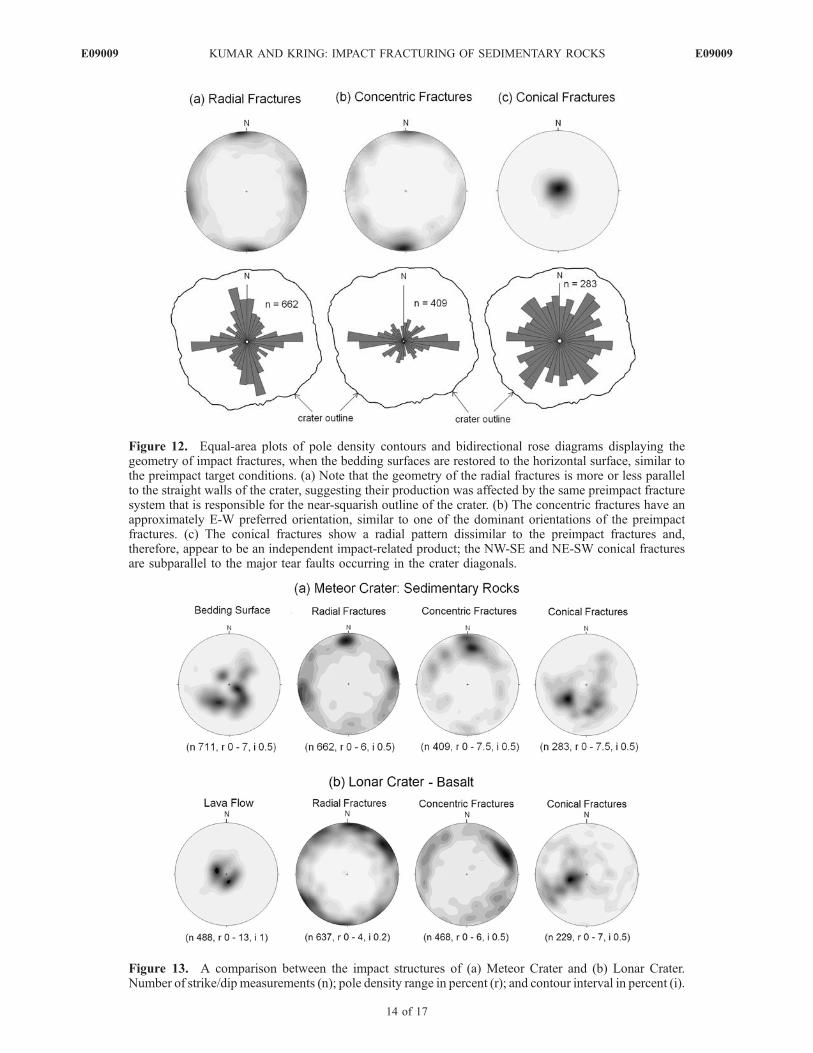
Figure 12. Equal-area plots of pole density contours and bidirectional rose diagrams displaying thegeometry of impact fractures, when the bedding surfaces are restored to the horizontal surface, similar tothe preimpact target conditions. (a) Note that the geometry of the radial fractures is more or less parallelto the straight walls of the crater, suggesting their production was affected by the same preimpact fracturesystem that is responsible for the near-squarish outline of the crater. (b) The concentric fractures have anapproximately E-W preferred orientation, similar to one of the dominant orientations of the preimpactfractures. (c) The conical fractures show a radial pattern dissimilar to the preimpact fractures and,therefore, appear to be an independent impact-related product; the NW-SE and NE-SW conical fracturesare subparallel to the major tear faults occurring in the crater diagonals.
Figure 13. A comparison between the impact structures of (a) Meteor Crater and (b) Lonar Crater.Number of strike/dip measurements (n); pole density range in percent (r); and contour interval in percent (i).
E09009 KUMAR AND KRING: IMPACT FRACTURING OF SEDIMENTARY ROCKS
14 of 17
E09009

target materials. In addition, in the presence of suchpreimpact weakness zones, the target would behave some-what differently in response to the impact. For example,motions would preferentially occur along these weaknesszones when shock waves pass through the target medium;this condition may inhibit the formation of new fractures,rather they would preferentially reactivate the existingones. For example, Gault et al. [1968] show that craterflow during excavation can be greatly influenced bypreexisting weakness zones. Nuclear explosion craters alsoprovide ample evidence in support of the reactivationprocess. For example, the explosion craters formed inthe alluvial flat of Yucca region of Nevada clearly suggestthat the development of explosion-related fracture systemsaround the craters have been greatly influenced by thepreexisting weakness zones in the bed rocks (Figure 14d).[21] Impact fractures form as a result of the passage of
shock waves in the target medium [see Sagy et al., 2004,and references therein]. For example, cratering experimentson water ice has indicated the relationship between thepassage of shock waves and the initiation of tensile radialfractures, which apparently form immediately after thepassage of seismic precursor waves [Arakawa et al.,2000]. Also in rocks, the radial fractures are formedimmediately behind the outgoing stress wave, whereas theconcentric fractures are initiated at later times and appear tobe related to the tensile phase of the stress pulse associatedwith sudden release of the impulsive force applied at thesurface [see Ahrens and Rubin, 1993, and references there-in]. The radial cracks are formed perpendicular to thedirection of peak tension, and thus normal to the quasispherical compressive wavefront. These mechanical pro-cesses can probably be extended to natural craters. Theimpact structures documented from Meteor Crater can thusbe related to the response of target rocks to the shock wavepropagation at the time of crater excavation and crater wallslumping related to the crater modification after excavation.However, the presence of preexisting weakness zones andtheir geometry significantly affect the interaction betweenthe target bedrock and the expanding shock wave, and, thus,the formation of the transient crater and any subsequentcrater wall collapse. For example the excavation flow andthe crater collapse should occur preferentially along anypreexisting weakness zones.
8. Conclusions
[22] Over 2500 structural measurements reveal that theupper crater walls of Meteor Crater are crosscut by three
distinct groups of fractures: radial, concentric, and conicalfractures. These are similar to the types of fractures thatoccur at Lonar Crater [Kumar, 2005]. We also confirm thatthe target was crosscut by three prominent sets of preimpacttectonic fracture systems. The majority of the preimpactfractures are parallel to the crater long walls, suggesting thateither the excavating flow preferentially hinged and over-turned material along the fractures or that crater wallslumping preferentially occurred along those fractures (orboth).[23] When the crater rim is restored to preimpact condi-
tion, the geometry of the radial and concentric fracturesresembles preimpact fracture populations, indicating thatcrater wall deformation and rim uplift was partly accom-modated by activation of preexisting fractures. In contrast,the conical fractures have orientations that are dissimilar tothe preimpact fractures and apparently formed as a directresult of impact deformation. Some of the fractures weretransformed into tear faults during the impact event. Fur-thermore, we confirm that a combination of fractured-controlled motion along the crater walls and along the tearfaults created the unusual square shape of Meteor Crater inplan view. This feature was subsequently enhanced bypreferential erosion along those fractures/faults and theauthigenic breccia in them. A symmetric distribution ofconical fractures appears to have been produced prior tocrater rim uplift and complex motion along tear faults. Thus,most conical fractures were produced prior to motion thatwas activated along radial and concentric fractures duringcrater rim uplift and subsequent slumping of inner craterwalls.[24] The preimpact fracture system in the Meteor Crater
region weakened the target lithologies affected by theimpact event. Not only did this entrench and facilitatemotion along radial and concentric fractures, it led to greaterrim uplift (at least 30 to 60 m) than that seen at Lonar Crater(only 20 m) in a stronger set of basaltic lava flows. Thesedata imply that structural deformation, crater rim uplift, andthe morphology of simple craters are influenced by thepreimpact structural state of target lithologies. Similaraffects may occur on the Moon where some impacts occurin relatively strong crystalline lithologies and others occurin weakened cataclastites or thick regolith. Likewise, similaraffects may occur on Mars, where some impacts may occurin relatively strong crystalline lithologies while others occurin relatively weak sedimentary and pyroclastic deposits.
Figure 14. (a and b) Secondary electron micrographs of impact craters formed on the solar panels of spacecraftsby micrometeoroid impacts [Graham et al., 2004] (with permission from the Geological Society of London); box b1 inFigure 14b shows the traces of radial (labeled R) and concentric (labeled C) fractures and the relationship between them.(c) A cross section of an experimentally produced crater on San Marcos gabbro by Polanskey and Ahrens [1990] (withpermission from Elsevier); note the occurrence of three types of fractures: radial (RF), concentric (CF), and near-surfacefractures (NSF), which all occur below a theoretical near-surface zone (TNSZ). (d) Fractures around a nuclear test site in theYucca flat region of Nevada [Barosh, 1968] (with permission from the Geological Society of America). This is a classicexample for a fracture pattern formed in response to the reactivation of preimpact fractures by a nuclear explosion. TheNW-SE (labeled 1) and NE-SW fractures (labeled 3) are subparallel to the preexisting faults/fractures in the basement rocksexposed around Yucca flat. However, a few of them are similar to the radial fractures seen in the meteorite impact craters.The concentric fractures (labeled 2) may be related to the crater collapse.
E09009 KUMAR AND KRING: IMPACT FRACTURING OF SEDIMENTARY ROCKS
15 of 17
E09009

Figure
14
E09009 KUMAR AND KRING: IMPACT FRACTURING OF SEDIMENTARY ROCKS
16 of 17
E09009

[25] Acknowledgments. We thank Drew N. Barringer, BarringerCrater Company, and Brad Andes, Meteor Crater Enterprises, for grantingpermission to conduct the field studies. P.S. thanks the staff of MeteorCrater Enterprises; Greg and Mandy for their help throughout the field-work; the Department of Science and Technology, Government of India forawarding the BOYSCOST Fellowship; James W. Head for hosting the visitto Brown University; Anne Cote, Nancy Christy, and William Collins forsupport; T. Seshunarayana for encouragement and support; V. P. Dimri,Director, NGRI for permission to publish this paper. Special thanks are dueto James W. Head and Peter H. Schultz for stimulating discussions. PatrickBarosh generously shared his experience of the geologic mapping ofNevada explosion craters, which is gratefully acknowledged. Thanks aredue to the Associate Editor (Jeffrey Plescia) and the reviewers (ChrisOkubo and David King Jr.) for very helpful reviews. LPI contribution 1387.
ReferencesAckermann, H. D., R. H. Godson, and J. S. Watkins (1975), A seismicrefraction technique used for subsurface investigations at Meteor Crater,Arizona, J. Geophys. Res., 80, 765–775, doi:10.1029/JB080i005p00765.
Ahrens, T. J., and A. M. Rubin (1993), Impact-induced tensional failure inrock, J. Geophys. Res., 98, 1185–1203, doi:10.1029/92JE02679.
Ahrens, T. J., K. Xia, and D. Coker (2002), Depth of cracking beneathimpact craters: New constraint for impact velocity, in Shock Compressionof Condensed Matter, edited by M. D. Furnish, N. N. Thadhani, andY. Horie, pp. 1393–1396, Am. Inst. of Phys., New York.
Ai, H., and T. J. Ahrens (2004), Dynamic tensile strength of terrestrial rocksand application to impact cratering, Meteorit. Planet. Sci., 39, 233–246.
Arakawa, M., K. Shirai, and M. Kato (2000), Shock wave and fracturepropagation in water ice by high velocity impact, Geophys. Res. Lett.,27, 305–308, doi:10.1029/1999GL010841.
Barosh, P. J. (1968), Relationships of explosion-produced fracture patternsto geologic structure in Yucca flat, Nevada test site, in Nevada Test Site,edited by E. B. Eckel, Mem. Geol. Soc. Am., 110, 199–217.
Brandt, D., and W. U. Reimold (1995), The geology of the Pretoria Saltpanimpact structure and the surrounding area, S. Afr. J. Geol., 98, 287–303.
Brandt, D., and W. U. Reimold (1999), The geology and geophysicalsignature of the Pretoria Saltpan (Tswaing) impact structure, in Investiga-tions Into the Origin, Age and Palaeoenvironments of the Pretoria Salt-pan, edited by T. C. Partridge, Mem. Geol. Surv. S. Afr., 85, 6–34.
Dence, M. R., R. A. F. Grieve, and P. B. Robertson (1977), Terrestrialimpact structures: Principal characteristics and energy considerations, inImpact and Explosion Cratering, edited by D. J. Roddy, R. O. Pepin, andR. B. Merrill, pp. 247–275, Pergamon, New York.
Fredriksson, K., P. Brenner, A. Dube, D. Milton, C. Mooring, and J. A.Nelen (1979), Petrology, mineralogy, and distribution of Lonar (India)and lunar impact breccias and glasses, Smithson. Contrib. Earth Sci., 22,1–12.
French, B. M. (1998), Traces of Catastrope [electronic], 120 pp., LunarPlanet. Inst., Houston, Tex. (Available online at http://www.lpi.usra.edu/publications/books/CB-954/CB-954.intro.html)
Fudali, R. F., D. J. Milton, K. Fredriksson, and A. Dube (1980), Morphol-ogy of Lonar Crater, India: Comparisons and implications,Moon Planets,23, 493–515, doi:10.1007/BF00897591.
Gault, D. E., W. L. Quaide, and V. R. Oberbeck (1968), Impact crateringmechanics and structures, in Shock Metamorphism of Natural Materials,Proceedings of the First Conference Held at NASA Goddard Space FlightCenter, Greenbelt, Maryland, April 14–16, edited by B. M. French andN. M. Short, pp. 87–99, Mono, Baltimore, Md.
Graham, G. A., A. T. Kearsley, G. Drolshagen, J. A. M. McDonnell, I. P.Wright, and M. M. Grady (2004), Mineralogy and microanalysis in thedetermination of cause of impact damage to spacecraft surfaces, in For-ensic Geoscience: Principles, Techniques and Applications, edited byK. Pye and D. J. Kroft, Geol. Soc. Spec. Publ., 232, 137–146.
Grieve, R. A. F., M. R. Dence, and P. B. Robertson (1977), Crateringprocesses: As interpreted from the occurrence of impact melts, in Impactand Explosion Cratering, edited by D. J. Roddy, R. O. Pepin, and R. B.Merrill, pp. 791–814, Pergamon, New York.
Grotzinger, J. P., et al. (2005), Stratigraphy and sedimentology of a dry towet eolian depositional system, Burns formation, Meridiani Planum,
Mars, Earth Planet. Sci. Lett., 240, 11–72, doi:10.1016/j.epsl.2005.09.039.
Kelley, V. C., and N. J. Clinton (1960), Fracture Systems and TectonicElements of the Colorado Plateau, 104 pp., Univ. of Press, N. M.,Albuquerque.
Kriens, B. J., E. M. Shoemaker, and K. E. Herdenhoff (1999), Geology ofthe Upheaval Dome impact structure, southeast Utah, J. Geophys. Res.,104, 18,867–18,887, doi:10.1029/1998JE000587.
Kring, D. A. (2007), Guidebook to the geology of Barringer MeteoriteCrater, Arizona (a.k.a Meteor Crater), LPI Contrib., 1355, 150 pp., Lunarand Planet. Inst., Houston, Tex.
Kumar, P. S. (2005), Structural effects of meteorite impact on basalt: Evi-dence from Lonar Crater, India, J. Geophys. Res., 110, B12402,doi:10.1029/2005JB003662.
National Geophysical Data Center (2007), Estimated value of magneticdeclination, NOAA Sat. Inf. Serv., Boulder, Colo. (Available at http://www.ngdc.noaa.gov/seg/geomag/jsp/declination.jsp.)
Okubo, C. H., and R. A. Schultz (2007), Compactional deformation bandsin Wingate Sandstone: Additional evidence of an impact origin forUpheaval Dome, Utah, Earth Planet. Sci. Lett., 256, 169 – 181,doi:10.1016/j.epsl.2007.01.024.
Partridge, T. C. (1999), Tswaing: Investigations into the origin, age, andpalaeoenvironments of the Pretoria Saltpan, Mem. Geol. Surv. S. Afr., 85,198 pp.
Pilon, J. A., R. A. F. Grieve, and V. L. Sharpton (1991), The subsurfacecharacter of Meteor Crater, Arizona, as determined by ground-probingradar, J. Geophys. Res., 96, 15,563–15,576, doi:10.1029/91JE01114.
Polanskey, C. A., and T. J. Ahrens (1990), Impact spallation experiments:Fracture patterns and spall velocities, Icarus, 87, 140–155, doi:10.1016/0019-1035(90)90025-5.
Regan, R. D., and W. J. Hinze (1975), Gravity and magnetic investigationsof Meteor Crater, Arizona, J. Geophys. Res., 80, 776–778, doi:10.1029/JB080i005p00776.
Roddy, D. J. (1978), Pre-impact geologic conditions, physical properties,energy calculations, meteorite and initial crater dimensions and orienta-tions of joints, faults and walls at Meteor Crater, Arizona, Proc. LunarPlanet. Sci. Conf., 11th, 3891–3930.
Roddy, D. J., J. M. Boyce, G. W. Colton, and A. L. Dial Jr. (1975), MeteorCrater, Arizona, rim drilling with thickness, structural uplift, diameter,depth, volume, and mass-balance calculations, Proc. Lunar Planet. Sci.Conf., 6th, 2621–2644.
Sagy, A., Z. Reches, and I. Roman (2001), Dynamic fracturing: Field andexperimental observations, J. Struct. Geol., 23, 1223–1239, doi:10.1016/S0191-8141(00)00190-5.
Sagy, A., J. Fineberg, and Z. Reches (2004), Shatter cones: Branched, rapidfractures formed by shock impact, J. Geophys. Res., 109, B10209,doi:10.1029/2004JB003016.
Scherler, D., T. Kenkmann, and A. Jahn (2006), Structural record of anoblique impact, Earth Planet. Sci. Lett., 248, 43– 53, doi:10.1016/j.epsl.2006.05.002.
Shoemaker, E. M. (1960), Penetration mechanics of high velocity meteor-ites, illustrated by Meteor Crater, Arizona, in 21st International Geolo-gical Congress, pp. 418–434, Int. Union of Geol. Sci., Trondheim,Norway.
Shoemaker, E. M. (1963), Impact mechanics at Meteor Crater, Arizona, inThe Moon, Meteorites, and Comets, edited by B. M. Middlehurst andG. P. Kuiper, chap. II, pp. 301–336, Univ. of Chicago, Chicago, Ill.
Shoemaker, E. M., and S. W. Kieffer (1974), Guidebook to the Geology ofMeteor Crater, Arizona, Publ. 17, 66 pp., Ariz. State Univ., Tempe.
Watters, W. A. (2006), Structure of polygonal impact craters at MeridianiPlanum, Mars and a model relating target structure to crater shape, LunarPlanet. Sci., XXXVII, Abstract 2163.
�����������������������P. S. Kumar, National Geophysical Research Institute, Council of Scientific
and Industrial Research, Hyderabad 500 606, India. ([email protected])D. A. Kring, Lunar and Planetary Institute, Universities Space Research
Association, Houston, TX 77058-1113, USA. ([email protected])
E09009 KUMAR AND KRING: IMPACT FRACTURING OF SEDIMENTARY ROCKS
17 of 17
E09009