Embed Size (px)
Citation preview

I:\CIRC\MSC\01\1497.doc
E
4 ALBERT EMBANKMENT
LONDON SE1 7SR Telephone: +44 (0)20 7735 7611 Fax: +44 (0)20 7587 3210
MSC.1/Circ.1497 16 December 2014
IMO/ILO/UNECE CODE OF PRACTICE FOR PACKING OF CARGO TRANSPORT UNITS (CTU CODE)
1 The Maritime Safety Committee, at its ninety-third session (14 to 23 May 2014), approved the IMO/ILO/UNECE Code of Practice for Packing of Cargo Transport Units (CTU Code), which was prepared by the Group of Experts for the revision of the IMO/ILO/UNECE Guidelines for Packing of Cargo Transport Units, subject to editorial improvements by the UNECE, ILO and IMO Secretariats, if necessary. 2 The Committee, at its ninety-fourth session (17 to 21 November 2014), having noted the concurrent approval of the CTU Code by the Inland Transport Committee of the UNECE, at its seventy-sixth session (25 to 27 February 2014), and the Governing Body of ILO, at its 322nd session (30 October to 13 November 2014), agreed to publish the CTU Code by means of an MSC circular, in cooperation with the UNECE and ILO. In this context, MSC 94 also approved MSC.1/Circ.1498 on Informative material related to the IMO/ILO/UNECE Code of Practice for Packing of Cargo Transport Units (CTU Code), which does not form part of the CTU Code but provides additional information. 3 Member Governments and international organizations are invited to bring the CTU Code, attached hereto, to the attention of all parties concerned*. 4 This circular revokes MSC/Circ.787 (IMO/ILO/UN ECE Guidelines for Packing of Cargo Transport Units).
***
* The text of the CTU Code and the Informative material related to the CTU Code can also be downloaded
from the UNECE website at http://www.unece.org/trans/wp24/guidelinespackingctus/intro.html

MSC.1/Circ.1497 Page 2
I:\CIRC\MSC\01\1497.doc
IMO/ILO/UNECE Code of Practice for Packing of Cargo Transport Units
(CTU Code)

MSC.1/Circ.1497 Page 3
I:\CIRC\MSC\01\1497.doc
Table of contents
Chapter 1. Introduction ..................................................................................................................... 5
Chapter 2. Definitions ....................................................................................................................... 9
Chapter 3. Key requirements ..........................................................................................................14
Chapter 4. Chains of responsibility and information .......................................................................16
Chapter 5. General transport conditions .........................................................................................21
Chapter 6. CTU properties ..............................................................................................................23
Chapter 7. CTU suitability ...............................................................................................................29
Chapter 8. Arrival, checking and positioning of CTUs ....................................................................32
Chapter 9. Packing cargo into CTUs ..............................................................................................38
Chapter 10. Additional advice on the packing of dangerous goods .................................................40
Chapter 11. On completion of packing .............................................................................................43
Chapter 12. Advice on receipt and unpacking of CTUs ...................................................................45
Chapter 13. Training in packing of CTUs .........................................................................................47
Annexes
Annex 1 Information flow .............................................................................................................49
Annex 2 Safe handling of CTUs .................................................................................................51
Annex 3 Prevention of condensation damages ..........................................................................56
Annex 4 Approval plates .............................................................................................................61
Annex 5 Receiving CTUs ............................................................................................................68
Annex 6 Minimizing the risk of recontamination..........................................................................83
Annex 7 Packing and securing cargo into CTUs ........................................................................92
Appendix 1 Packaging marks .................................................................................123
Appendix 2 Friction factors .....................................................................................128
Appendix 3 Practical methods for the determination of the friction factor µ ...........130
Appendix 4 Specific packing and securing calculations .........................................132
Appendix 5 Practical inclination test for determination of the efficiency of cargo securing arrangements ........................................................................137
Annex 8 Access to tank and bulk tops, working at height .........................................................140
Annex 9 Fumigation .............................................................................................................145
Annex 10 Topics for consideration in a training programme ......................................................147

MSC.1/Circ.1497 Page 4
I:\CIRC\MSC\01\1497.doc
Preamble The use of freight containers, swap bodies, vehicles or other cargo transport units substantially reduces the physical hazards to which cargoes are exposed. However, improper or careless packing of cargoes into/onto such units, or lack of proper blocking, bracing and lashing, may be the cause of personnel injury when they are handled or transported. In addition, serious and costly damage may occur to the cargo or to the equipment. The types of cargoes carried in freight containers has expanded over many years and innovations such as use of flexitanks and developments allow heavy, bulky items which were traditionally loaded directly into the ships' hold (e.g. stone, steel, wastes and project cargoes), to be carried in cargo transport units. The person who packs and secures cargo into/onto the cargo transport unit (CTU) may be the last person to look inside the unit until it is opened at its final destination. Consequently, a great many people in the transport chain will rely on the skill of such persons, including:
road vehicle drivers and other road users when the unit is transported by road;
rail workers, and others, when the unit is transported by rail;
crew members of inland waterway vessels when the unit is transported on inland waterways;
handling staff at terminals when the unit is transferred from one transport mode to another;
dock workers when the unit is loaded or unloaded;
crew members of a seagoing ship during the transport operation;
those who have a statutory duty to inspect cargoes; and
those who unpack the unit.
All persons, such as the above, passengers and the public, may be at risk from a poorly packed freight container, swap body or vehicle.

MSC.1/Circ.1497 Page 5
I:\CIRC\MSC\01\1497.doc
Chapter 1. Introduction 1.1 Scope 1.1.1 The aim of this IMO/ILO/UNECE Code of Practice for Packing of Cargo Transport
Units (CTU Code) is to give advice on the safe packing of cargo transport units (CTUs) to those responsible for the packing and securing of the cargo and by those whose task it is to train people to pack such units. The aim is also to outline theoretical details for packing and securing as well as to give practical measures to ensure the safe packing of cargo onto or into CTUs.
1.1.2 In addition to advice to the packer, the CTU Code also provides information and
advice for all parties in the supply chain up to and including those involved in unpacking the CTU.
1.1.3 The CTU Code is not intended to conflict with, or to replace or supersede, any
existing national or international regulations which may refer to the packing and securing of cargo in CTUs, in particular existing regulations which apply to one mode of transport only, e.g. for transport of cargo in railway wagons by rail only.
1.2 Safety 1.2.1 Improperly packed and secured cargo, the use of unsuitable CTUs and the
overloading of CTUs may endanger persons during handling and transport operations. Improper declaration of the cargo may also cause dangerous situations. The misdeclaration of the CTU's gross mass may result in the overloading of a road vehicle or a rail wagon or in the allocation of an unsuitable stowage position on board a ship thus compromising the safety of the ship.
1.2.2 Insufficient control of humidity may cause severe damages to and collapse of the
cargo and cause also the loss of the stability of the CTU. 1.3 Security 1.3.1 It is important that all personnel involved in the packing, security sealing, handling,
transport and processing of cargo are made aware of the need for vigilance and the diligent application of practical procedures to enhance security, in accordance with national legislation and international agreements.
1.3.2 Guidance on the security aspects of the movement of CTUs intended for carriage by
sea may be found in a variety of documents including the International Convention for the Safety of Life at Sea (SOLAS), 1974, as amended; the International Ship and Port Facility Security (ISPS) Code; the ILO/IMO Code of Practice on Security in Ports; and the Standards and the Publicly Available Specifications developed or being developed by the International Organization for Standardization (ISO) to address cargo security management and other aspects of supply chain security. Furthermore, the World Customs Organization (WCO) has developed a SAFE Framework of standards to secure and facilitate global trade.

MSC.1/Circ.1497 Page 6
I:\CIRC\MSC\01\1497.doc
1.4 How to use the CTU Code 1.4.1 This Code comprises 13 chapters. Most of them refer to one or more annexes which
is highlighted in the text where applicable. Further practical guidance and background information are available as informative material1, which does not constitute part of this Code. Table 1 at the end of this chapter provides a summary of contents.
1.4.2 More information on the consequences of improper packing procedures is provided
in informative material IM1. 1.4.3 Following the introduction in chapter 1, chapter 2 lists definitions of terms which are
used throughout the Code. Chapter 3 provides an overview of basic safety issues related to the packing of CTUs, briefly described as "dos and don'ts". Detailed information on how to comply with these "dos" and how to avoid the "don'ts" are contained in the following chapters and in the related annexes.
1.4.4 Chapter 4 identifies the chains of responsibility and communication for the principle
parties in the supply chain and is supplemented with annex 1 on information flow and, particularly for terminal operators, with annex 2 on the safe handling of CTUs. Information on typical documents related to transport may be obtained from informative material IM2.
1.4.5 Chapter 5 (general transport conditions) describes the acceleration forces and the
climatic conditions to which a CTU is exposed during transport. Annex 3 provides additional guidance on the prevention of condensation damages.
1.4.6 Chapter 6 (CTU properties), chapter 7 (CTU suitability) and chapter 8 (arrival,
checking and positioning of CTUs) should be considered to select the appropriate CTU for the cargo to be carried and to ensure that the CTU is fit for its intended purpose. Additional guidance to these topics is provided in annex 4 (approval plates), annex 5 (receiving CTUs) and annex 6 (minimizing the risk of recontamination). More information on the properties of the various CTU types is provided in informative material IM3, more information on species of concern regarding recontamination may be obtained from informative material IM4.
1.4.7 Chapter 9 (packing cargo into CTUs) is the core chapter of this Code dealing with
the actual packing operation. This chapter directs the user to the related provisions in annex 7, where detailed information on load distribution, securing arrangements, capacity of securing devices and methods for the evaluation of the efficiency of a certain securing arrangement are provided. This annex is supplemented with appendices on packaging marks, friction factors and on calculations for load distribution and cargo securing. Guidance for working on the top of tank CTUs or solid bulk CTUs is provided in annex 8. To facilitate the evaluation of the efficiency of cargo securing arrangements, one sound practical tool is the "quick lashing guide" provided in informative material IM5. In addition, very detailed information on intermodal load distribution is provided in informative material IM6. Information on manual handling of cargo is provided in informative material IM7. Information on the transport of perishable cargo is provided in informative material IM8.
1 Available at www.unece.org/trans/wp24/guidelinespackingctus/intro.html.

MSC.1/Circ.1497 Page 7
I:\CIRC\MSC\01\1497.doc
1.4.8 Chapter 10 provides additional advice on the packing of dangerous goods. Chapter 11 describes the actions required on the completion of packing. Information on CTU seals is provided in informative material IM9.
1.4.9 Chapter 12 contains advice on the receipt and unpacking of CTUs and is
supplemented with annex 5 (receiving CTUs) and annex 9 (fumigation). Additional information on the testing of gases is provided in informative material IM10.
1.4.10 Chapter 13 outlines the required qualification of personnel engaged in the packing of
CTUs. The topics for consideration in a training programme are listed in annex 10. 1.5 Standards Throughout this Code and in its annexes and appendices, any national or regional
standards are referenced for information only. Administrations may substitute other standards that are considered equivalent.
MSC.1/Circ.1497 Page 8
I:\CIRC\MSC\01\1497.doc
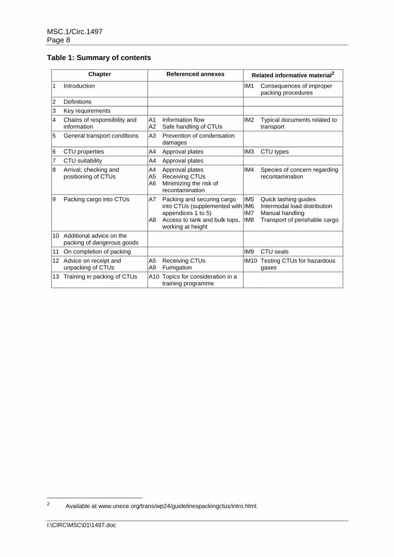
Table 1: Summary of contents
Chapter Referenced annexes Related informative material2
1 Introduction IM1 Consequences of improper packing procedures
2 Definitions
3 Key requirements
4 Chains of responsibility and information
A1 A2
Information flow Safe handling of CTUs
IM2 Typical documents related to transport
5 General transport conditions A3 Prevention of condensation damages
6 CTU properties A4 Approval plates IM3 CTU types
7 CTU suitability A4 Approval plates
8 Arrival, checking and positioning of CTUs
A4 A5 A6
Approval plates Receiving CTUs Minimizing the risk of recontamination
IM4 Species of concern regarding recontamination
9 Packing cargo into CTUs A7 A8
Packing and securing cargo into CTUs (supplemented with appendices 1 to 5) Access to tank and bulk tops, working at height
IM5 IM6 IM7 IM8
Quick lashing guides Intermodal load distribution Manual handling Transport of perishable cargo
10 Additional advice on the packing of dangerous goods
11 On completion of packing IM9 CTU seals
12 Advice on receipt and unpacking of CTUs
A5 A9
Receiving CTUs Fumigation
IM10 Testing CTUs for hazardous gases
13 Training in packing of CTUs A10 Topics for consideration in a training programme
2 Available at www.unece.org/trans/wp24/guidelinespackingctus/intro.html.

MSC.1/Circ.1497 Page 9
I:\CIRC\MSC\01\1497.doc
Chapter 2. Definitions
For the purpose of this Code, the following is defined:
Absolute humidity of air Actual amount of water vapour in the air, measured in g/m3 or g/kg.
Boundary Refers to the edges or walls of the CTU, and surrounds the cargo deck.
Cargo deck The area within the CTU boundaries onto which packages may be placed and secured.
Cargo transport unit (CTU)
A freight container, swap body, vehicle, railway wagon or any other similar unit in particular when used in intermodal transport.
Carrier The party who, in a contract of carriage, undertakes to perform or to procure the performance of carriage by rail, road, sea, inland waterway or by a combination of such modes. Can be further classified as:
Road haulier;
Rail operator;
Shipping line.
Clean CTU A CTU free from:
Any previous cargo residues;
Any securing materials used from previous consignments;
Any marks, placards or signs associated with previous consignments;
Any detritus (waste) that may have accumulated in the CTU;
Visible pests and other living or dead organisms, including any part, gametes, seeds, eggs or propagules of such species that may survive and subsequently reproduce; soil; organic matter;
All other items covered by contamination, infestation and invasive alien species that can be discovered upon visible inspection.
Closed CTU A CTU which totally encloses the contents by permanent structures with complete and rigid surfaces. CTUs with fabric sides or tops are not considered as closed cargo transport units.
Condensation Conversion of water vapour into a liquid state. Condensation usually starts when air is cooled down to its dew point in contact with cold surfaces.
Consignee The party to whom a cargo is consigned under a contract of carriage or a transport document or electronic transport record.
Also known as the receiver.
Consignor The party who prepares a consignment for transport. If the consignor contracts the transport operation with the carrier, the consignor will undertake the function of the shipper and may also be known as:
The shipper (maritime);
The sender (road transport).
Consolidator The party performing a consolidation service for others.
MSC.1/Circ.1497 Page 10
I:\CIRC\MSC\01\1497.doc
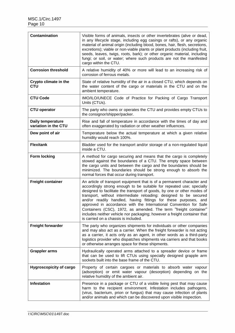
Contamination Visible forms of animals, insects or other invertebrates (alive or dead, in any lifecycle stage, including egg casings or rafts), or any organic material of animal origin (including blood, bones, hair, flesh, secretions, excretions); viable or non-viable plants or plant products (including fruit, seeds, leaves, twigs, roots, bark); or other organic material, including fungi; or soil, or water; where such products are not the manifested cargo within the CTU.
Corrosion threshold A relative humidity of 40% or more will lead to an increasing risk of corrosion of ferrous metals.
Crypto climate in the CTU
State of relative humidity of the air in a closed CTU, which depends on the water content of the cargo or materials in the CTU and on the ambient temperature.
CTU Code IMO/ILO/UNECE Code of Practice for Packing of Cargo Transport Units (CTUs).
CTU operator The party who owns or operates the CTU and provides empty CTUs to the consignor/shipper/packer.
Daily temperature variation in the CTU
Rise and fall of temperature in accordance with the times of day and often exaggerated by radiation or other weather influences.
Dew point of air Temperature below the actual temperature at which a given relative humidity would reach 100%.
Flexitank Bladder used for the transport and/or storage of a non-regulated liquid inside a CTU.
Form locking A method for cargo securing and means that the cargo is completely stowed against the boundaries of a CTU. The empty space between the cargo units and between the cargo and the boundaries should be minimized. The boundaries should be strong enough to absorb the normal forces that occur during transport.
Freight container An article of transport equipment that is of a permanent character and accordingly strong enough to be suitable for repeated use; specially designed to facilitate the transport of goods, by one or other modes of transport, without intermediate reloading: designed to be secured and/or readily handled, having fittings for these purposes, and approved in accordance with the International Convention for Safe
Containers (CSC), 1972, as amended. The term "freight container" includes neither vehicle nor packaging; however a freight container that is carried on a chassis is included.
Freight forwarder The party who organizes shipments for individuals or other companies and may also act as a carrier. When the freight forwarder is not acting as a carrier, it acts only as an agent, in other words as a third-party logistics provider who dispatches shipments via carriers and that books or otherwise arranges space for these shipments.
Grappler arms Hydraulically operated arms attached to a spreader device or frame that can be used to lift CTUs using specially designed grapple arm sockets built into the base frame of the CTU.
Hygroscopicity of cargo Property of certain cargoes or materials to absorb water vapour (adsorption) or emit water vapour (desorption) depending on the relative humidity of the ambient air.
Infestation Presence in a package or CTU of a visible living pest that may cause harm to the recipient environment. Infestation includes pathogens, (virus, bacterium, prion or fungus) that may cause infection of plants and/or animals and which can be discovered upon visible inspection.

MSC.1/Circ.1497 Page 11
I:\CIRC\MSC\01\1497.doc
Intermodal operator The party who provides a service to transfer and/or stow CTUs. May be subdivided into:
Maritime terminal operator;
Rail terminal;
Inland waterway port.
Invasive alien species An alien (non-native) species whose introduction and/or spread
threatens biological diversity "Alien species" refers to a species,
subspecies or lower taxon, introduced outside its natural past or present distribution; includes any part, gametes, seeds, eggs, or propagules of such species that might survive and subsequently reproduce. It includes pests and quarantine pests of non-native origin.
Invasive alien species may be carried within and on a wide range of substrates, both organic and inorganic.
Misdeclared cargo A cargo transported in a CTU which is different from that declared on the transport documents.
Misdeclared gross mass A CTU where the combined mass of the cargo and the CTU is different from the mass declared on the transport/shipping documents. See also overloaded and overweight.
Mould growth threshold A relative humidity of 75% or more will lead to an increasing risk of mould growth on substances of organic origin like foodstuff, textiles, leather, wood, ore substances of non-organic origin such as pottery.
Non-regulated goods Substances and articles that are not covered by the applicable dangerous goods transport regulations.
Overloaded A CTU where the combined mass of the cargo and the CTU is greater than the maximum permitted gross mass.
Overpack An enclosure used by a single shipper to contain one or more packages and to form one unit for convenience of handling and stowage during transport.
Examples of overpacks are a number of packages either:
Placed or stacked on to a load board such as a pallet and secured by strapping, shrink-wrapping, stretch-wrapping or other suitable means; or
Placed in a protective outer packaging such as a box or crate.
Overweight A CTU where the combined mass of the cargo and the CTU is less than the maximum permitted gross mass but exceeds either:
The maximum gross mass shown on the transport/shipping documents; or
The road or rail maximum masses when combined with the tare of the container carrying vehicle.
Package The complete product of the packing operation, consisting of the packaging and its contents as prepared for transport;
Packaging Receptacles and any other components or materials necessary for the receptacle to perform its containment function.
Packer The party that loads, places or fills the cargo within or on the CTU; the packer may be contracted either by the consignor, by the shipper, by the freight forwarder or by the carrier; if the consignor or the shipper packs a CTU within his own premises, the consignor or the shipper is also the packer.

MSC.1/Circ.1497 Page 12
I:\CIRC\MSC\01\1497.doc
Packing The placing, loading and filling cargo into and onto a CTU.
Pest Any visible species, strain or biotype of plant, animal or pathogenic agent injurious to plants or plant products.
Quarantine pest A pest of potential economic importance to the area endangered thereby and not yet present there, or present but not widely distributed and being officially approved.
Recontamination The result of pests and other living organisms (including their nests, eggs, egg sacks, and body parts) being found in or on a clean CTU.
Reinforced vehicle body Vehicle body, having a reinforced structure (in Europe, complies with European standard EN 12642, paragraph 5.3).
Relative humidity of air Actual absolute humidity expressed as percentage of the saturation humidity at a given temperature.
Roll-on/roll-off ship (ro-ro)
A method of maritime cargo service using a vessel with ramps which allows wheeled vehicles to be loaded and discharged without cranes. Also refers to any specialized vessel designed to carry ro-ro cargo.
Saturation humidity of air
Maximum possible humidity content in the air depending on the air temperature.
Scantling A piece of sawn timber, such as a batten, that has a small cross section.
Set point Temperature setting on the controller of the refrigeration unit.
Shelf life The recommended period that a perishable product may be retained in a saleable condition during which the defined quality of a specified proportion of the goods remains acceptable under expected (or specified) conditions of distribution, storage and display.
Shipper The party named on the bill of lading or waybill as shipper and/or who concludes a contract of carriage (or in whose name or on whose behalf a contract of carriage has been concluded) with a carrier.
Also known as the sender.
Solebar Main beam of a rail wagon/car.
Standard vehicle body Vehicle body, without reinforced structure (in Europe, complies with European standard EN 12642, paragraph 5.2), which, depending on cargo weight and friction, requires additional securing of cargo using lashing equipment.
Storage life The period that the product is kept at the lowest possible temperature starting soonest after picking/harvesting and ending at the time that the product is taken out the refrigerated conditions for delivery to consumers at which time the shelf life period starts.
Unit load Palletized load or prepacked unit with a footprint conforming to pallet dimensions and suitable for loading into an CTU. See also unitized cargo.
Unitized cargo A single item or a number of items packaged, packed, or arranged in a specified manner and capable of being handled as a unit. Unitization may be accomplished by placing the item or items in an overpack or by banding them securely together. Also known as a unit load.
Unpacking The removal of cargo from a CTU.

MSC.1/Circ.1497 Page 13
I:\CIRC\MSC\01\1497.doc
Ventilated container Closed type of container, similar to a general purpose freight container but designed to allow air exchange between its interior and the outside atmosphere. Has a ventilating system designed to accelerate and increase the natural convection of the atmosphere within the container as uniformly as possible, either by non-mechanical vents at both the upper and lower parts of their cargo space, or by internal or external mechanical means.
Water content of cargo Latent water and water vapour in a hygroscopic cargo or associated material, usually stated as percentage of the wet mass of cargo.

MSC.1/Circ.1497 Page 14
I:\CIRC\MSC\01\1497.doc
Chapter 3. Key requirements
This chapter identify those actions and tasks that are key to the safe packing and transport of cargo.
3.1 General
Do arrange for a safe working environment.
Do use safe handling equipment.
Do use appropriate personal protective equipment.
Do check that the CTU and any cargo securing equipment are in sound condition.
Do not smoke, eat or drink during packing, securing or unpacking.
3.2 Planning
Do select the most suitable CTU type to accommodate the cargo for the intended transport.
Do prepare a packing plan when deemed necessary.
Do select the securing methods best adapted to the characteristics of the cargo, the mode of transport and the properties of the CTU.
Do not exceed the permitted payload limits of the unit or the maximum allowed gross mass according to the CSC3, national road and rail regulations.
3.3 Packing
Do distribute heavy cargo appropriately over the floor area.
Do observe all handling instructions and symbols on packages such as "this side up".
Do load with the centre of gravity correctly located in the CTU.
Do not concentrate heavy cargo on small areas of the floor.
Do not load with eccentric load distribution.
Do not build up irregular layers of packages if it can be avoided.
Do not stow heavy goods on top of light goods.
Do not stow goods with tainting odours together with sensitive merchandise.
Do not pack wet and damp goods if it can be avoided.
Do not use securing or protection equipment which is incompatible with the cargo.
3.4 Packing of dangerous goods
Do check that all packages are properly marked and labelled.
Do pack dangerous goods according to applicable dangerous goods regulations.
Do pack dangerous goods near the door of the CTU where possible.
Do affix required placards, marks and signs on the exterior of the CTU.
3 International Convention for Safe Containers, 1972.

MSC.1/Circ.1497 Page 15
I:\CIRC\MSC\01\1497.doc
Do not pack incompatible goods which should be segregated.
Do not pack damaged packages.
3.5 Securing
Do fill void spaces when necessary.
Do use blocking or lashing or a combination of these methods to prevent the cargo from sliding and tipping in any direction.
Do secure the cargo in a way that forces are distributed over an appropriate area of a unit.
Do secure each single loaded item independently where necessary.
Do use non-slip surface material to refrain packages from sliding where appropriate.
Do use hooks or shackles to fasten lashings where applicable.
Do not secure the cargo with devices overstressing the structure of the CTU or the cargo.
Do not overstress securing devices.
Do not over tighten securing devices so that the packaging or goods are damaged.
Do not fasten web lashings by means of knots.
3.6 On completion of packing
Do determine the correct gross mass of the CTU.
Do affix a seal when required.
Do include the CTU number, the correct gross mass and, when required, the seal number in the appropriate documents.
Do provide a packing certificate when required.
3.7 Unpacking
Do check that the identification number on the CTU and, when the CTU should be sealed, the seal serial number, are as shown on the transport documentation.
Do check the exterior of the CTU for signs of leakage or infestation.
Do use proper equipment to cut the seal if affixed.
Do ensure the CTU is safe to enter. Be aware that the atmosphere in the CTU may be dangerous – ventilate before entering.
Do open the CTU with caution as cargo might fall out.
Do record every package as it is removed noting any markings and damages.
Do remove all securing and protection material for reuse, recycling or disposal.
Do clean the interior of the CTU to remove all traces of the cargo, especially loose powders, grains and noxious materials and fumigants, unless otherwise agreed with the CTU operator.
Do remove all marks, placards and signs regarding the previous consignment from the exterior of the CTU once it has been cleaned.

MSC.1/Circ.1497 Page 16
I:\CIRC\MSC\01\1497.doc
Chapter 4. Chains of responsibility and information Note: Definitions are given in chapter 2.
4.1 Chain of responsibility
4.1.1 In general, transport operations using CTUs in particular, involve various parties each of whom have a responsibility to ensure that the cargo is transported through the supply chain without incident. Notwithstanding any national legislation or contracts between the involved parties the chain of responsibility discussed below identifies functional responsibilities of the parties involved.
4.1.2 Although the carrier generally, in a contract of carriage is responsible under that contract to deliver the cargo in the same condition as received, it is the shipper who should deliver a cargo which is safe and suitable for transport. Thus, the shipper remains responsible for any deficiency of the CTU that is a result of poor packing and securing. However, when the shipper is neither the packer nor the consignor, the packer and the consignor should fulfil their obligation to the shipper ensuring that the CTU is safe for transport. If not the shipper may hold those parties responsible for any faults or deficiencies that can be attributed to poor packing, securing, handling or reporting procedures.
4.1.3 Within this chain of responsibilities, each party in the chain should comply with their individual responsibilities and in doing so increase safety and reduce the risk of injury to persons involved in the supply chain.
4.1.4 All persons involved in the movement of CTUs also have a duty to ensure, in accordance with their roles and responsibilities in the supply chain, that the CTU is not infested with plants, plant products, insects or other animals, or that the CTU is not carrying illegal goods or immigrants, contraband or undeclared or misdeclared cargoes.
4.1.5 The supply chain is a complex operation and individual modes of transport may have defined terms for parties within the supply chain which are not consistent with other modes of transport.
4.1.6 A single entity may undertake one or more of the functions listed below. The flow of information between the functions is discussed further in annex 1.
4.2 Functions within the supply chain
Between the different functions involved in an intermodal transport chain, the tasks are assigned as follows:
4.2.1 The CTU operator is responsible for providing CTUs that:
Are fit for purpose;
Comply with international structural integrity requirements;
Comply with international or national safety regulations;
Are clean, free of cargo residues, noxious materials, plants, plant products and visible pests.
4.2.2 The consignor is responsible for:
Correctly describing the goods including the mass of the total payload;

MSC.1/Circ.1497 Page 17
I:\CIRC\MSC\01\1497.doc
Notifying the packer/shipper of any unusual transport parameters of individual packages, for example, the offset of the centre of gravity or transport temperatures which should not be exceeded or undercut;
Ensuring that packages and unit loads are suitable to withstand the stresses which are to be expected under normal transport conditions;
Providing all the information that is required for proper packing;
Ensuring that goods in packages and unit loads are adequately secured to prevent damage during transport;
Ensuring that goods are ventilated so that any noxious or harmful gases are permitted to vent off before packing;
Ensuring that dangerous goods are correctly classified, packed and labelled;
Ensuring the dangerous goods transport document is completed, signed and transmitted to the packer, forwarder, shipper (if not the consignor) and carrier as applicable.
4.2.3 The packer is responsible for:
Ensuring that the CTU is checked before packing and that the condition of the CTU is suitable for the cargo to be transported;
Ensuring that the floor of the CTU is not overstressed during packing operations;
Ensuring that the cargo is correctly distributed in the CTU and properly supported where necessary;
Ensuring that the CTU is not overloaded;
Ensuring that the cargo is sufficiently secured in the CTU;
Ensuring that measures are put in place to prevent the movement of plants, plant products and visible pests, such as closing doors and tarpaulins once packing has started but not taking place and lights that minimize the attraction of insects;
Properly closing the CTU and sealing it, when required, and reporting seal details to the shipper. CTUs used for international transport should be sealed;
Fitting marks and placards to the CTU as required by dangerous goods regulations;
Fitting the fumigation mark if any fumigant has been used as part of the packing process;
Accurately determining the gross mass4 of the CTU and transmitting it to the shipper;
Ensuring that no incompatible dangerous goods are packed. Account should be taken of all dangerous goods legislations during the complete transport chain;
Providing the container/vehicle packing certificate (new document or signed statement in the dangerous goods transport documentation as appropriate) and forwarding any documentation to the shipper.
4 The gross mass of the CTU needs to be verified before any transport operation commences. Incorrect
gross masses are a hazard for any mode of transport. Therefore, the gross mass verification should be carried out before the unit leaves the premises of the packer. If a certain transport mode deems it necessary that a reverification has to take place when the CTU is transferred from one mode to another, this is beyond the scope of this Code and may be regulated in the regulations of that mode. Where a cargo is to be transported by road or rail only, the packer need only provide the mass of the cargo and any packing and securing material to the carrier when the tare of the transport vehicle is not known.

MSC.1/Circ.1497 Page 18
I:\CIRC\MSC\01\1497.doc
The packer should also pass on information relating to any freight container with a reduced stacking capacity (less than 192,000 kg marked on the CSC safety approval plate)5, to the shipper.
4.2.4 The shipper is responsible for ensuring that:
The work distribution concerning packing and securing is clearly agreed and communicated to the consignor and carrier/carriers;
A suitable CTU is used for the intended cargo for the intended transport;
A CTU is requested which is safe for transport and is clean, free of cargo residues, noxious materials, plants, plant products and visible pests before being supplied to the consignor or packer;
Suitable modes of transport are selected to minimize the risk of accidents and damages for the actual cargo;
All required documents are received from the consignor and from the packer;
The cargo inside the CTU is fully and accurately described;
The gross mass of the CTU is accurately determined;
The accurate description of the cargo6 is communicated to the carrier as early as required by the carrier;
The verified gross mass is communicated to the carrier as early as required by the carrier;
In case of dangerous goods, the transport document and (for sea transport) the packing certificate is transmitted to the carrier before the transport commences respectively as early as required by the carrier;
In the case of temperature controlled goods, the correct temperature set point is entered into the control unit and onto the transport/shipping documents;
Ensuring that a seal, where required, is affixed immediately upon completion of the packing of the CTU;
The seal number, where required, is communicated to the carrier;
Any extraordinary properties such as reduced stacking capacity or out of gauge are communicated to the carrier;
The shipper's declaration is accurate;
Shipping instructions are despatched to the carrier on time and that the CTU meets the outbound delivery window;
The CTU arrives at the terminal before the stated cargo cut off time;
The information concerning the consignment, description of packages and, in the case of freight containers, the verified gross mass is transmitted to the consignee.
5 As of January 1st 2012, all freight containers with reduced stacking or racking strength are required by the
International Convention for Safe Containers (CSC) to be marked in accordance with the latest version of ISO 6346: Freight containers – Coding, identification and marking.
6 A description of the cargo should include a description of the goods and the packaging, for example wine
in a flexitank, hard frozen hanging beef sides or the number and type of packages. However, national and/or regional regulations may impose additional requirements for the scope and level of detail of cargo descriptions, including usage of Harmonized System (HS) codes.

MSC.1/Circ.1497 Page 19
I:\CIRC\MSC\01\1497.doc
4.2.5 The road haulier is responsible for:
Confirming that the gross mass, length, width and height of the vehicle are within the national road/highway regulations limits;
Ensuring that the driver is able to get sufficient rest and does not drive when fatigued;
Except when the CTU is a trailer, securing the CTU properly on the trailer or chassis;
Moving the CTU in such a manner that there are no exceptional stresses placed on the CTU or the cargo.
4.2.6 The rail haulier is responsible for:
Handling the CTU in a manner that would not cause damage to the cargo;
Except when the CTU is a rail wagon, securing the CTU properly on the rail wagon.
4.2.7 The intermodal operator is responsible for:
Ensuring that appropriate pest prevention methods are in place, which may include removal of muds and soils from the CTU;
Complying with annex 2.
4.2.8 The carrier is responsible for:
Monitoring agreed temperatures in the CTUs where applicable and reacting to changes as appropriate;
Securing the CTU on the means of transport;
Transporting the CTU in compliance with agreements and all applicable regulations;
Providing trained personnel to deal with all cargo types (break-bulk, bulk wet and dry cargoes, dangerous goods, out of gauge, refrigerated, uncontainerized).
4.2.9 The consignee/receiver of CTUs is responsible for:
Not overstressing the floor of the CTU during unpacking operations;
Correctly ventilating the CTU before entering;
Confirming that the atmosphere within the CTU is not hazardous before permitting persons to enter it;
Detecting any damage to the CTU and to notify the carrier;
Returning the CTU to the CTU operator completely empty and clean, unless otherwise agreed;
Removing all marks, placards or signs regarding the previous consignments.
4.2.10 Shippers of empty CTUs and operators of empty CTUs are encouraged to have practices and arrangements in place to ensure that they are empty.

MSC.1/Circ.1497 Page 20
I:\CIRC\MSC\01\1497.doc
4.2.11 All parties identified within section 4.2 should minimize the risk of recontamination of CTUs when in their custody. This may include the following:
Implementation of appropriate pest management programs;
Removal of any plants, plant products or visible pests taking into account the roles and responsibilities of each party within the supply chain and, further, the impossibility of inspecting the interior of closed and sealed CTUs for recontamination.
For more information see annex 6. 4.2.12 All parties should ensure that the flow of information is transmitted to parties
identified in the transport contract along the supply chain. The information should include:
The identification, in accordance with a risk assessment7, of risks to the integrity of the CTU that may be present for all or some part of the journey;
CTU identification;
Seal number (where required);
Verified gross mass of the CTU;
Accurate description of the cargo carried in the CTU;
The correct description of dangerous goods;
Correct and appropriate transport documentation;
Any information required for safety, security, phytosanitary, veterinary, Customs or other regulatory purposes.
7 For example, ISO 31000 Risk management – Principles and guidelines.

MSC.1/Circ.1497 Page 21
I:\CIRC\MSC\01\1497.doc
Chapter 5. General transport conditions
5.1 Within the supply transport chain, there are a number of different stresses acting on the cargo. These stresses may be grouped into mechanical and climatic stresses. Mechanical stresses are forces acting on the cargo under specific transport conditions. Climatic stresses are changes of climatic conditions including extremely low or high temperatures.
5.2 During transport various forces will act on the cargo. The force acting on the cargo is
the mass of the cargo (m) which is measured in kg or ton, multiplied by the acceleration (a) which is measured in m/s² :
F = m ∙ a Acceleration considered during transport are the gravitational acceleration (a = g = 9.81 m/s²) and acceleration caused by typical transport conditions such as by the braking or rapid change of traffic lanes by a road vehicle or by the motions of a ship in heavy sea. These accelerations are expressed as product of the gravitational acceleration (g) and a specific acceleration coefficient (c) e.g. a = 0.8 g.
5.3 The following tables provide the applicable acceleration coefficients for the different modes of transport and for the various securing directions. To prevent a cargo from movement, the cargo has to be secured in longitudinal and transverse direction according to the worst combination of horizontal and corresponding vertical accelerations. The securing arrangement has to be designed to withstand the forces due to accelerations in each horizontal direction (longitudinal and transverse) separately (see chapter 9 and annex 7).
Road transport
Securing in
Acceleration coefficients
Longitudinally (cx) Transversely (cy)
Minimum vertically down (cz)
forward rearward
Longitudinal direction 0.8 0.5 - 1.0
Transverse direction - - 0.5 1.0
Rail transport (combined transport)
Securing in
Acceleration coefficients Longitudinally (cx) Transversely
(cy) Minimum vertically
down (cz)
forward rearward
Longitudinal direction 0.5 (1.0)† 0.5 (1.0)† - 1.0 (0.7)†
Transverse direction - - 0.5 1.0 (0.7)†
† The values in brackets apply to shock loads only with short impacts of 150 milliseconds
or shorter, and may be used, for example, for the design of packaging.
Sea transport
Significant wave height in sea
area Securing in
Acceleration coefficients Longitudinally
(cx) Transversely
(cy) Minimum
vertically down (cz)
A Hs ≤ 8 m Longitudinal direction 0.3 - 0.5
Transverse direction - 0.5 1.0

MSC.1/Circ.1497 Page 22
I:\CIRC\MSC\01\1497.doc
Sea transport
Significant wave height in sea
area Securing in
Acceleration coefficients Longitudinally
(cx) Transversely
(cy) Minimum
vertically down (cz)
B 8 m < Hs ≤ 12 m Longitudinal direction 0.3 - 0.3
Transverse direction - 0.7 1.0
C Hs > 12 m Longitudinal direction 0.4 - 0.2
Transverse direction - 0.8 1.0
5.4 The effect of short term impact or vibrations should always be considered.
Therefore, whenever the cargo cannot be secured by blocking, lashing is required to prevent the cargo from being significantly displaced, taking into account the characteristics of the cargo and the mode of transport. The mass of the cargo alone, even when combined with a high friction coefficient (see appendix 2 to annex 7), does not sufficiently secure the cargo as the cargo can move due to vibrations.
5.5 The significant 20-years return wave height (Hs) is the average of the highest
one-third of waves (measured from trough to crest) that is only exceeded once in 20 years. The allocation of geographic sea areas to the respective significant wave heights is shown in the following table:
A B C
Hs ≤ 8 m 8 m < Hs ≤ 12 m Hs > 12 m
Baltic Sea (incl. Kattegat) Mediterranean Sea Black Sea Red Sea Persian Gulf Coastal or inter-island voyages in following areas: Central Atlantic Ocean (between 30°N and 35°S) Central Indian Ocean (down to 35°S) Central Pacific Ocean (between 30°N and 35°S)
North Sea Skagerak English Channel Sea of Japan Sea of Okhotsk Coastal or inter-island voyages in following areas: South-Central Atlantic Ocean (between 35°S and 40°S) South-Central Indian Ocean (between 35°S and 40°S) South-Central Pacific Ocean (between 35°S and 45°S)
unrestricted
Sources:
The Royal Netherlands Meteorological Institute (KNMI): The KNMI/ERA-40 Wave Atlas, derived from 45 years of ECMWF reanalysis data (ed. S.Caires, A.Stern, G.Komen and V.Swail), last updated 2011, Hs 100-yr return values, 1958 – 2000
5.6 During longer voyages, climatic conditions (temperature, humidity) are likely to vary
considerably. These may affect the internal conditions in a CTU which may give rise to condensation on cargo or internal surfaces (see annex 3).
5.7 Whenever a specific cargo might be damaged when exposed to high or low
temperatures during transport, the use of a CTU specially equipped for keeping the cargo temperature within acceptable limits should be considered (see chapter 7).

MSC.1/Circ.1497 Page 23
I:\CIRC\MSC\01\1497.doc
Chapter 6. CTU properties
Note: Definitions are given in chapter 2. 6.1 Introduction 6.1.1 When planning a consignment for transport the shipper should ensure that the CTU
best suited for the cargo and the probable route is selected. If the shipper is uncertain about which CTU to select, further information can be obtained by contacting the CTU operator.
6.1.2 Packers should acquaint themselves with the characteristics of the CTU with
particular reference to:
Net mass capacity;
Flooring strength;
Anchor and securing points;
Thermal capabilities;
Sealing;
Weatherproofness.
6.2 Freight containers 6.2.1 The external and internal dimensions of most freight containers are standardized by
ISO. 6.2.2 The maximum gross mass and the permitted payload of a freight container depend
on standardized design parameters. The International Convention for Safe Containers requires each freight container to carry a CSC safety approval plate, where the maximum permitted gross mass is specified (see subsection 8.2.1 and annex 4, section 1). Additionally, the tare mass and the payload are marked in painted letters on the door or on the rear end of the freight container.
6.2.3 With the exception of platforms (a container deck without walls), packed freight
containers are capable of being stacked. This feature is mainly used in land-based storage areas and on ships during a sea passage. The permissible stacking mass is displayed on the approval plate. Freight containers with a stacking mass equal to or greater than 192,000 kg may be transported without restriction. However, freight containers with a stacking mass value less than 192,000 kg do also exist and require special attention when used for intermodal transport, in particular for the stowage in stacks on seagoing vessels (see subsections 7.3.1 and 8.2.1).
6.2.4 General purpose freight containers are available as closed freight containers,
ventilated containers and open top containers. The side walls are capable of withstanding a uniform load equal to 60% of the permitted payload. The front wall and the door end are capable of withstanding 40% of the permitted payload. These limitations are applicable for a homogenous load on the relevant wall area and do not exclude the capability of absorbing higher forces by the framework of the freight container. The container floor is primarily designed to sustain the total payload homogeneously distributed over the bottom structure. This results in limitations for concentrated loads (see annex 7, section 3).

MSC.1/Circ.1497 Page 24
I:\CIRC\MSC\01\1497.doc
6.2.5 Most general purpose freight containers have a limited number of lashing rings or bars. When lashing rings are fitted, the anchor points at the bottom have a maximum securing load (MSL) of at least 10 kN in any direction. Recently built freight containers have, in many cases, anchor points with a MSL of 20 kN. The lashing points at the top side rails have a MSL of at least 5 kN8.
6.2.6 Floors on freight containers covered by the CSC are only required to withstand an
axle load of 5,460 kg or 2,730 kg per wheel9 although they may be built to withstand a greater axle load. The CTU operator can provide more precise information.
6.2.7 Closed freight containers generally have labyrinth protected openings for venting
(pressure compensation), but these openings do not measurably support air exchange with the ambient atmosphere. Special type "ventilated containers" have weatherproof ventilation grills built into the top and bottom side rails and the front top rail and bottom sill, through which the natural convection inside the freight container is intensified and a limited exchange of air and humidity with the ambient atmosphere is established.
6.2.8 An open top container is similar to a closed freight container in all respects except
that it has no permanent rigid roof. It may have a flexible and movable or removable cover, e.g. of canvas, plastic or reinforced plastic material. The cover is normally supported by movable or removable roof bows. In some cases the removable roof is a compact steel construction suitable to be lifted off in one piece. The header (transverse top rail above the doors) is generally movable or removable (known as swinging headers). The headers are part of the container strength and should be fitted to have full strength of the freight container.
6.2.9 Open side containers have a curtain or canvas on one or both sides, a rigid roof and
rear doors. While the strength of the end walls is similar to that of closed freight containers, the side curtain provides limited or no restraint capability. Open side containers are not covered by ISO standards.
6.2.10 Platforms and platform based containers are characterized by having no side
superstructure except either fixed or collapsible end walls (flatracks) or are designed without any superstructure (platforms). The benefit of collapsible end walls is that the flatrack may be efficiently stacked when transported in empty condition for repositioning.
6.2.11 Flatracks and platforms have a bottom structure consisting of at least two strong
longitudinal H-beam girders, connected by transverse stiffeners and lined by solid wooden boards. For securing of cargo units, strong lashing brackets are welded to the outer sides of the longitudinal bottom girders with a MSL of at least 30 kN according to the standard. In many cases the lashing points have a MSL of 50 kN. Cargo may also be secured in longitudinal direction by shoring to the end walls of flatracks. These end walls may be additionally equipped with lashing points of at least 10 kN MSL.
6.2.12 Thermal containers, commonly referred to as reefer containers, are designed for the
transport of cargo under temperature control. Such cargo is generally homogeneously packed and tightly stowed from wall to wall. Therefore, the side and end wall strength is similar to that of general purpose freight containers. However,
8 See ISO 1496-1:2013 Freight containers – Specification and testing – Part 1: General cargo containers for
general purposes, Annex C.
9 International Convention for Safe Containers, 1972, Annex II.

MSC.1/Circ.1497 Page 25
I:\CIRC\MSC\01\1497.doc
thermal containers are generally not equipped with anchor and lashing points. When a cargo needs to be secured by lashings, specific fittings may be affixed to the "T" section gratings, thus providing the required anchor points.
6.2.13 A tank container comprises two basic elements, the tank shell (or shells in case of a
multiple-compartment tank container) and the framework. The framework is equipped with corner fittings and renders the tank suitable for intermodal transport. The frame should comply with the requirements of the CSC. If dangerous goods are intended to be carried in the tank, the shell and all fittings such as valves and pressure relief devices should comply with the applicable dangerous goods regulations.
6.2.14 A non-pressurized dry bulk container is a container especially designed for the
transport of dry solids, capable of withstanding the loads resulting from filling, transport motions and discharging of non-packaged dry bulk solids, having filling and discharging apertures and fittings. There are freight containers for tipping discharge, having filling and discharge openings and also a door. A variant is the hopper type for horizontal discharge, having filling and discharge openings but no doors. The front and rear end walls of solid bulk containers are reinforced and so constructed to bear a load equal to 60% of the payload. The strength of the side walls is similar to that of general purpose freight containers.
6.3 Regional and domestic containers Regional and domestic containers are designed and manufactured to meet the
needs of local transport operations. They may have the appearance of a freight container, but unless fitted with valid CSC safety approval plates they should not be used in international transport.
6.4 Swap bodies 6.4.1 A swap body is a regional transport containment of a permanent character designed
for road and rail transport within Europe and complying with European standards. Swap bodies are generally 2.5 m or 2.55 m wide and are subdivided into three length categories:
Class A: 12.2 to 13.6 m long (maximum gross mass 34 tons);
Class B: 30ft (9.125 m long);
Class C: 7.15, 7.45 or 7.82 m long (maximum gross mass 16 tons).
6.4.2 Swap bodies are fixed and secured to the vehicles with the same devices as freight containers, but owing to the size difference, these fittings are not always located at the swap body corners.
6.4.3 Stackable swap bodies have top fittings enabling the handling with standard freight
container handling equipment. Alternatively, the swap body may be handled using grappler arms, inserted into the four recesses in the bottom structure. Swap bodies not suitable for stacking can only be handled with grappler arms. Class C swap bodies can be transferred from the road vehicle to their supporting legs and returned to the vehicle by lowering or raising the carrier vehicle on its wheels.
6.4.4 The standard box type swap body has a roof, side walls and end walls, and a floor
and has at least one of its end walls or side walls equipped with doors. Class C swap bodies complying with standard EN 283 have a defined boundary strength: the front and the rear end are capable to withstand a load equal to 40% of the permitted

MSC.1/Circ.1497 Page 26
I:\CIRC\MSC\01\1497.doc
payload, the sides are capable to withstand 30% of the permitted payload. For a cover-stake body the drop sides are designed to withstand a force equal to 24% of the maximum permitted payload and the remaining part of the side is designed to withstand 6% of the maximum permitted payload. The sides in a curtain sided swap body may not be used for cargo securing unless purposely designed to do so.
6.4.5 Floors of swap bodies are built to withstand corresponding axle loads of 4,400 kg
and wheel loads of 2,200 kg (reference: EN 283). Such axle loads are typical for forklift trucks with a lifting capacity of 2.5 tons.
6.4.6 The curtain-sided swap body is designed similarly to a standard curtain side semi-
trailer. It has an enclosed structure with rigid roof and end walls and a floor. The sides consist of removable canvas or plastic material. The side boundary may be enforced by battens.
6.4.7 A thermal swap body is a swap body that has insulating walls, doors, floor and roof.
Thermal swap bodies may be insulated, but not necessarily equipped with mechanical device for cooling. A variant is the mechanically refrigerated swap reefer.
6.4.8 A swap tank is a swap body that consists of two basic elements, the tank or tanks,
and the framework. The tank shell of a swap tank is not always fully enclosed by the frame work.
6.4.9 A swap bulker is a swap body that consists of the containment for dry solids in bulk
without packaging. It may be fitted with one or more round or rectangular loading hatches in the roof and "cat flap" or "letter box" discharge hatches in the rear and/or front ends.
6.5 Roll trailers 6.5.1 Roll trailers are exclusively used for the transport of goods in ro-ro ships and are
loaded or unloaded and moved in port areas only. They present a rigid platform with strong securing points at the sides, and occasionally brackets for the attachment of cargo stanchions. The trailer rests on one or two sets of low solid rubber tyres at about one third of the length and on a solid socket at the other end. This end contains a recess for attaching a heavy adapter, the so-called gooseneck. This adapter has the king-pin for coupling the trailer to the fifth wheel of an articulated truck.
6.5.2 The packing of a roll trailer with cargo or cargo units should be planned and
conducted under the conception that the cargo should be secured entirely by lashings. However, roll trailers are available equipped with standardized locking devices for the securing of freight containers and swap bodies.
6.6 Road vehicles 6.6.1 Road vehicles are available in a number of different formats and designs. 6.6.2 Most vehicles have a strong front wall integrated into the closed superstructure.
Closed superstructures of road vehicles may be provided with arrangements for applying approved seals.
6.6.3 Semi-trailers suitable for combined road/rail transport are generally equipped with
standardized recesses for being lifted by suitable cranes, stackers or forklift trucks, to enable the lifting transfer from road to rail or vice versa.

MSC.1/Circ.1497 Page 27
I:\CIRC\MSC\01\1497.doc
6.6.4 Road vehicles are allocated a specific maximum payload. For road trucks and full trailers the maximum payload is a constant value for a given vehicle and should be documented in the registration papers. However, the maximum allowed gross mass of a semi-trailer may vary to some extent with the carrying capacity of the employed articulated truck as well as in which country it is operating. The total gross combination mass, documented with the articulated truck, should never be exceeded.
6.6.5 The actual permissible payload of any road vehicle depends distinctly on the
longitudinal position of the centre of gravity of the cargo carried. In general, the actual payload should be reduced if the centre of gravity of the cargo is conspicuously off the centre of the loading area. The reduction should be determined from the vehicle specific load distribution diagram (see annex 7, subsection 3.1.7). Applicable national regulations on this matter should be observed. In particular closed freight containers transported on semi-trailers with the doors at the rear of the vehicle quite often tend to have their centre of gravity forward of the central position. This may lead to an overloading of the articulated truck if the container is packed toward its full payload.
6.6.6 The boundaries of the loading platform of road vehicles may be designed and made available in a strength that would be sufficient – together with adequate friction – to retain the cargo under the specified external loads of the intended mode of transport. Such advanced boundaries may be specified by national or regional industry standards. However, a large number of road vehicles are equipped with boundaries of less resistivity in longitudinal and transverse direction, so that any loaded cargo should be additionally secured by lashings and/or friction increasing material. The rating of the confinement capacity of such weak boundaries may be improved if the resistance capacity is marked and certified for the distinguished boundary elements of the vehicle.
6.6.7 In Europe, European standard EN 12642 would apply. According to this, there are two levels of requirements of vehicle sides and ends: Code L and Code XL. The strength requirements of the side walls for the Code L vehicles are similar to the requirements for sides of swap bodies according to the standard EN 283 (see paragraph 6.4.4). The side walls of Code XL vehicles are designed to withstand a force equal to 40% of the permitted payload uniformly distributed over the side up to 75% of the height of the side, independently of the type of vehicle. The front wall of Code L vehicles is designed to take up a force equal to 40% of the permitted payload, the maximum however is 50 kN. For Code XL vehicles the front wall is designed to withstand a force equivalent to 50% of the payload without any further limit. The rear wall of Code L vehicles is designed to withstand a force equal to 30% of the permitted payload, the maximum however is 31 kN. For Code XL vehicles the rear wall is designed to withstand a force equivalent to 40% of the payload without any further limit.
6.6.8 Road vehicles are generally equipped with securing points along both sides of the loading platform. These points may consist of flush arranged clamps, securing rails or insertable brackets and should be designed for attaching the hooks of web lashings and chains. The lashing capacity of securing points varies with the maximum gross mass of the vehicle. The majority of vehicles is fitted with points of a lashing capacity (LC) or maximum securing load (MSL) of 20 kN. Another type of variable securing devices are pluck-in posts, which may be inserted into pockets at certain locations for providing intermediate barriers to the cargo. The rating of the lashing capacity of the securing points may be improved if their capacity is marked and certified. Modern vehicles are often equipped with continuous connecting points for lashing bars on each side, thus to enable the affixing of the lashing bars exactly in the required positions to block the cargo against movement towards the rear side.
MSC.1/Circ.1497 Page 28
I:\CIRC\MSC\01\1497.doc
6.7 Railway wagons 6.7.1 In intermodal transport, railway wagons are used for two different purposes: First,
they may be used as carrier unit to transport other CTUs such as freight containers, swap bodies or semi-trailers. Second, they may be used as a CTU themselves which is packed or loaded with cargo and run by rail or by sea on a railway ferry.
6.7.2 The first mentioned purpose is exclusively served by open wagons, which are
specifically fitted with devices for securing freight containers, inland containers and swap bodies or have dedicated bedding devices for accommodating road vehicles, in particular semi-trailers. The second mentioned purpose is served by multifunctional closed or open wagons, or wagons which have special equipment for certain cargoes, e.g. coil hutches, pipe stakes or strong lashing points.
6.7.3 On board ferries the shunting twin hooks are normally used for securing the wagon
to the ship's deck. These twin hooks have a limited strength and therefore some wagons are equipped with additional stronger ferry eyes. These external lashing points should never be used for securing cargo to the wagon.
6.7.4 The maximum payload is generally not a fixed value for the distinguished wagon,
but allocated case by case by means of the intended track category and the speed category. More details are provided in annex 4, subsection 5.1.5.
6.7.5 In case of concentrated loads a reduction of the payload is required, which depends
on the loaded length and the way of bedding the concentrated load. The applicable load figures are marked on each wagon. Also any longitudinal or transverse eccentricity of concentrated loads is limited by the individual axle load capacity or the wheel load capacity. More details are provided in annex 4, subsection 5.1.6.
6.7.6 Closed railway wagons are designed for the compact stowage of cargo. The
securing of cargo should be accomplished by tight packing or blocking to the boundaries of the wagon. However, wagons equipped with sliding doors should be packed in a way that doors remain operable.
6.7.7 When a railway ferry is operating between railway systems of different gauges,
wagons which are capable for changing their wheel sets over from standard gauge to broad gauge or vice versa are employed. Such wagons are identified by the first two figures of the wagon number code.

MSC.1/Circ.1497 Page 29
I:\CIRC\MSC\01\1497.doc
Chapter 7. CTU suitability
7.1 Suitability in general
7.1.1 Freight containers and some other types of CTUs (e.g. swap bodies for rail transport in Europe) require type approval. In addition, depending on the type, the verification of a periodic or continuous examination scheme might be required as well. A CTU requiring approval (and examination) and not bearing a valid approval plate is not suitable for transport (see subsection 8.2.1).
7.1.2 Freight containers and swap bodies showing serious defects in their structural components (e.g. top and bottom side rails, top and bottom end rails, door sills and header, floor cross members, corner posts and corner fittings) may place persons into danger and are therefore not suitable for transport (see subsection 8.2.2).
7.1.3 Road vehicles, semi-trailers and railway wagons showing deterioration in major structural components or other obvious defects impede the safe traffic on road or rail and are therefore not suitable for transport.
7.2 Suitability for the cargo 7.2.1 All cargo which is sensitive against weather conditions such as rain, snow, dust and
sunlight, or against theft and other consequences of easy access should be carried in a closed or sheeted CTU. Freight containers, closed or sheeted swap bodies, semi-trailers and other road vehicles are suitable for most cargoes.
7.2.2 Single packages such as:
Cartons stacked by hand;
Drums or similar packages stacked by forklift truck; or
Any kind of palletized cargo
can be packed and preferably stowed from boundary to boundary. However, it depends on the type of CTU, whether such firm stowage alone provides sufficient cargo securing or whether additional securing is needed (see section 9.4).
7.2.3 Certain cargoes such as cocoa or other agricultural produce are sensitive against climatic effects and may be damaged when the humidity within the CTU is condensed due to a decrease of temperature. This effect is specific for long distance sea transport and can be controlled by appropriate ventilation. Standard freight containers however allow only restricted air changes. Therefore, specially designed containers with increased ventilation may be preferred for such sensitive cargo.
7.2.4 Certain perishable cargoes such as foodstuffs and, in particular, deep frozen products, require transport at low temperatures. Other products, e.g. certain chemicals, need to be protected from frost. Such commodities should be transported in insulated and temperature controlled CTUs which can be refrigerated or heated as appropriate.
7.2.5 Heavy items such as granite and marble blocks may also be packed into closed CTUs. However, this cargo cannot be simply stowed from wall to wall. Bracing and blocking against the frame of the CTU and/or lashing to the securing points is necessary (see annex 7, section 4.3). As the lashing capacity of the securing points in general purpose freight containers is limited, such standard containers might not be appropriate for certain large and heavy cargo items. Instead, platforms or flatracks could be used.

MSC.1/Circ.1497 Page 30
I:\CIRC\MSC\01\1497.doc
7.2.6 Cargo items of extreme dimensions may not fit inside a standard CTU as they exceed the inner width, length and perhaps also the height of the unit. Such cargo may be accommodated on a platform or on a flatrack. When the cargo is only "over-height" but not "over-width" an open top CTU may also be suitable.
7.2.7 Heavy cargo items lifted by a forklift truck may result in a front axle load exceeding the maximum permissible concentrated load inside a CTU. For example modern freight containers are designed to withstand a force of 0.5 kN/cm2 which may limit package masses to approximately 3 to 3.5 tons depending on the type of forklift truck used. For heavy cargo, open top, open side or platform CTUs should be used so that the cargo can be loaded from the top or from the side without a need to drive into the CTU with the forklift truck. For load distribution, see annex 7, section 3.1.
7.2.8 Some cargoes such as scrap metal are usually handled by grabs or by conveyors.
When this cargo is to be loaded into a CTU and a conveyor is not available, the only suitable CTU type is an open top CTU capable to be loaded with grabs. Placing the CTU vertically on its end and "pouring" the cargo in through the open doors is not permitted.
7.2.9 General purpose CTUs are not suitable for certain long, heavy and irregular cargo items such as timber logs, as the side walls are not designed to withstand the acceleration forces of such cargo and may suffer bulging damages. Stowage in shape of a pyramid and securing by lashing is extremely difficult in a freight container, because the securing points are not accessible after this cargo is loaded, unless the lashings are arranged before loading. Therefore, such cargo should preferably be carried only on platform or flatrack CTUs.
7.2.10 Liquid and solid bulk cargoes should be preferably transported in tank CTUs or solid
bulk CTUs. Under certain conditions, liquid bulk cargo may be carried in flexitanks which are stowed in CTUs. Similarly, solid bulk may be carried in general purpose CTUs which are equipped with a liner. However, CTUs used for such purposes should be suitably reinforced10 and prepared, operational restrictions regarding the permissible payload should be observed (see annex 7, section 5).
7.3 Suitability for the transport mode
7.3.1 Freight containers, including swap bodies and regional containers designed for stacking and approved under the CSC are basically suitable for all modes of transport. However, freight containers having an allowable stacking mass of less than 192,000 kg marked on the approval plate (see annex 4, section 1) require special stowage on board a ship, where the superimposed stacking mass will not exceed the permitted limits as marked on the plate. Furthermore, some freight containers and swap bodies may have a gross mass of 34 tons or higher for which some road chassis and railcars will not be capable of carrying such heavy units. Therefore, especially for heavy massed containers, it is of utmost importance to arrange for an appropriate chassis and tractor vehicle or railcar, as applicable.
7.3.2 As the maximum permissible payload of a railcar is not a fixed value for the distinguished wagon but depends in addition on the track category of the railway network (see annex 4, section 5.1), the railway operator should be contacted when necessary, in order to prevent overloading.
10 False bulkheads may be fitted at the rear (door) end as required.

MSC.1/Circ.1497 Page 31
I:\CIRC\MSC\01\1497.doc
7.3.3 Swap bodies and semi-trailers are designed for an easy change of the means of transport. In most cases this might be an interchange between different carrier vehicles for swap bodies or different tractor vehicles for semi-trailers. When an intermodal change from road to rail is intended, it should be ensured that the swap body or the semi-trailer is capable of being lifted by grappler arms and approved for rail transport.
7.3.4 CTUs on ro-ro ships 7.3.4.1 Before dispatching a CTU for carriage on a ro-ro, the shipper needs to confirm with
the CTU operator and/or the ro-ro ship operator whether specific requirements apply. Further, the shipper needs to ensure that the CTU to be used is fit for this kind of transport.
7.3.4.2 When road vehicles or semi-trailers are intended to be transported on a ro-ro ship,
they should be equipped with securing points of a defined minimum strength in sufficient number according to the following table11:
Gross vehicle mass (GVM (tons))
Minimum number of securing points on each side of the vehicle
Minimum strength of each securing point (kN)
3.5 ≤ GVM ≤ 20 2
GVM x 10 x 1.2 n
20 < GVM ≤ 30 3
30 < GVM ≤ 40 4
40 < GVM ≤ 50 5
50 < GVM ≤ 60 6
where n is the total number of securing points on each side of the vehicle
7.3.4.3 Road trains, comprising two or more trailers, require each trailer to be considered in isolation and be fitted with, and secured by, the minimum number of securing points for the GVM of that trailer component. Semi-trailer tractor or towing vehicles are excluded from the table and should be provided with two securing points or a towing coupling at the front of the vehicle.
7.3.4.4 When railway wagons are intended to be transported on a railway ferry, they should
be able to pass over the kink angle of the ferry ramp and to pass through the track curves on the ferry vessel. In general, there are more restrictions for wagons equipped with bogies than for wagons equipped with two wheel sets only. The details should be clarified with the ferry line operator.
7.3.4.5 Railway wagons should be equipped with securing points on both sides in sufficient
number when used in ferry traffic. To determine the required number and strength of securing points the ferry operator should be contacted. The maximum permitted axle loads and maximum permitted loads per linear metre depend on the properties of the ferry ramp and of the characteristics of the ferry vessels employed in the respective ferry service.
11 See IMO Resolution A.581(14).

MSC.1/Circ.1497 Page 32
I:\CIRC\MSC\01\1497.doc
Chapter 8. Arrival, checking and positioning of CTUs
8.1 CTU Arrival 8.1.1 The type of CTU used for the transport will influence:
The process of confirming that it is fit for use;
The CTU's positioning to suit the packing operation and timing;
The planning of the cargo packing.
8.1.2 The CTU operator will advise of the estimated time of arrival and departure. The type of CTU may influence these timings:
Rigid road vehicles will come with a driver and it would be expected that the time to pack the vehicle will be dictated by any time restrictions that local regulations may impose.
Detachable CTUs, such as trailers and rail wagons may be left at the packer's facility and the tractor unit/motor unit permitted to depart if the packing procedure is extended.
Class C swap bodies fitted with legs can be unloaded onto their legs and the tractor unit/engine unit plus trailer (if present) may be driven away.
Freight containers and class A and B swap bodies can remain on the trailer or be unloaded and placed on the ground.
CTUs remaining on trailers may be left for a period of time.
8.1.3 If the consignment requires more than one CTU then it is important to plan what packages go within each unit and how each CTU is managed: multiple units might be delivered all at once and the packer can manage positioning of each unit to suit the facility available. Another option is to deliver the units sequentially so that the container operator delivers an empty unit and picks up a fully packed one.
8.1.4 In both cases planning what packages go into each unit will be important. Demand
at the destination may require particular packages to be packed in each CTU. However such demand can have an adverse effect on the load distribution, on possibility to secure the cargo properly, on the segregation of dangerous goods and also on volume utilisation. It is therefore important that a complete plan may be generated for all packages and CTUs prior to the start of packing the first CTU.
8.2 CTU checks 8.2.1 Approval plates 8.2.1.1 Freight containers and, under certain conditions, also swap bodies and road trailers
may be required by applicable regulations to bear a safety approval plate. Details of the markings required on swap bodies and road trailers destined for transport by rail within the European railway network and data plates on freight containers transported internationally by sea and covered by the International Convention for Safe Containers (CSC) are shown in annex 4.
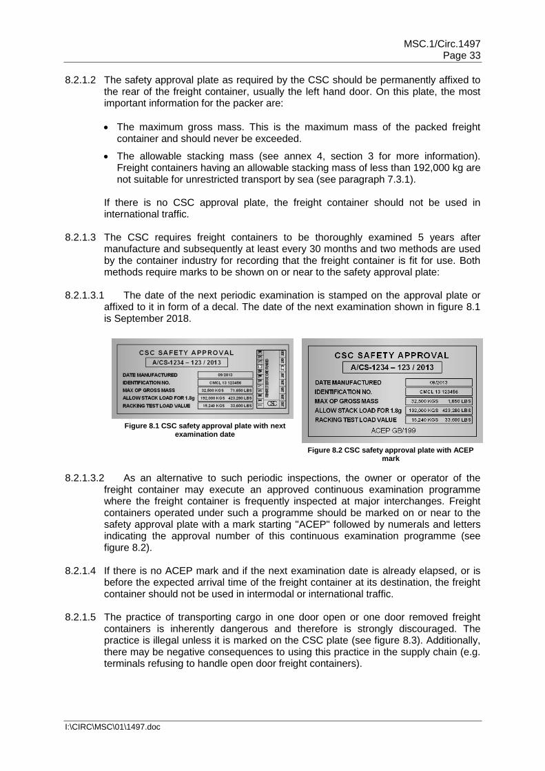
MSC.1/Circ.1497 Page 33
I:\CIRC\MSC\01\1497.doc
8.2.1.2 The safety approval plate as required by the CSC should be permanently affixed to the rear of the freight container, usually the left hand door. On this plate, the most important information for the packer are:
The maximum gross mass. This is the maximum mass of the packed freight container and should never be exceeded.
The allowable stacking mass (see annex 4, section 3 for more information). Freight containers having an allowable stacking mass of less than 192,000 kg are not suitable for unrestricted transport by sea (see paragraph 7.3.1).
If there is no CSC approval plate, the freight container should not be used in international traffic.
8.2.1.3 The CSC requires freight containers to be thoroughly examined 5 years after
manufacture and subsequently at least every 30 months and two methods are used by the container industry for recording that the freight container is fit for use. Both methods require marks to be shown on or near to the safety approval plate:
8.2.1.3.1 The date of the next periodic examination is stamped on the approval plate or
affixed to it in form of a decal. The date of the next examination shown in figure 8.1 is September 2018.
Figure 8.1 CSC safety approval plate with next
examination date
Figure 8.2 CSC safety approval plate with ACEP mark
8.2.1.3.2 As an alternative to such periodic inspections, the owner or operator of the freight container may execute an approved continuous examination programme where the freight container is frequently inspected at major interchanges. Freight containers operated under such a programme should be marked on or near to the safety approval plate with a mark starting "ACEP" followed by numerals and letters indicating the approval number of this continuous examination programme (see figure 8.2).
8.2.1.4 If there is no ACEP mark and if the next examination date is already elapsed, or is
before the expected arrival time of the freight container at its destination, the freight container should not be used in intermodal or international traffic.
8.2.1.5 The practice of transporting cargo in one door open or one door removed freight
containers is inherently dangerous and therefore is strongly discouraged. The practice is illegal unless it is marked on the CSC plate (see figure 8.3). Additionally, there may be negative consequences to using this practice in the supply chain (e.g. terminals refusing to handle open door freight containers).

MSC.1/Circ.1497 Page 34
I:\CIRC\MSC\01\1497.doc
Figure 8.3 CSC safety approval plate for one door off operation
8.2.2 Exterior checks 8.2.2.1 The structural framework, the walls and roof of a CTU should be in good condition,
and not significantly distorted, cracked or bent. The CTU operator is responsible for delivering a CTU that complies with international structural integrity requirements and international or national safety regulations. If the structural integrity is in doubt, advice should be sought from supervisory personnel or the CTU operator.
8.2.2.2 The doors of a CTU should work properly and be capable of being securely locked
and sealed in the closed position, and properly secured in the open position. Door gaskets and weather strips should be in good condition.
8.2.2.3 A folding CTU with movable or removable main components should be correctly
assembled. Care should be taken to ensure that removable parts not in use are packed and secured inside the unit.
8.2.2.4 Any component that can be adjusted or moved, or a pin that can be engaged and
withdrawn, should be checked to see that it can be moved easily and retained correctly. This is of particular importance for folding flatracks where the end-walls are retained in the upright position by a pin or shoot bolt which should be engaged and retained from accidentally pulling out by a retaining flap.
8.2.2.5 Removable or swinging headers of open top CTUs should be inspected. The header
is generally supported by removable pins. Checks should be made to ensure that the pins are of the correct length and freely removable at both ends. Checks should also be made for signs of cracks around the hinges.
8.2.2.6 Road vehicles that are likely to be carried on rail wagons or on ro-ro ships should be
provided with points for securing them. There should be equal numbers of lashing points on both sides of the vehicle and each point should be intact and free from serious corrosion or damage.
8.2.2.7 For sheeted vehicles or containers the side, top or all round covers should be
checked as being in satisfactory condition and capable of being secured. Loops or eyes in such canvas which take the fastening ropes, as well as the ropes themselves, should be in good condition. All lashing strap ratchet tighteners should be able to be engaged and operate correctly.
8.2.2.8 Labels, placards, marks or signs regarding previous usages of the CTU should be
removed. Permanently affixed signs and marks may never be removed.

MSC.1/Circ.1497 Page 35
I:\CIRC\MSC\01\1497.doc
8.2.2.9 When undertaking the exterior checks, the CTU should be checked for any signs of recontamination particularly:
Along bottom rails;
Within forklift pockets;
In and around the twist lock fittings;
Underside and cross members;
On tops where necessary.
8.2.3 Interior checks 8.2.3.1 Before entering a closed CTU, the doors should be opened for a period of time –
enough to allow the internal atmosphere to regularize with the ambient. Care should be taken to ensure that during this period, animals and insects should not enter the CTU.
8.2.3.2 The CTU should be free from major damage, with no broken flooring or protrusions
such as nails, bolts, special fittings, etc. which could cause injury to persons or damage to the cargo.
8.2.3.3 The CTU should not show liquids or persisting stains on flooring and side walls.
There are a number of different materials and surface treatments used for flooring in CTUs. Sealed surfaces generally can be cleaned with absorbent materials. Where a stain can be transferred by wiping a gloved hand over it, the CTU should not be used and a replacement CTU should be requested.
8.2.3.4 A CTU should be weatherproof unless clearly designed otherwise (e.g. flatrack).
Patches or repairs to solid walls should be carefully checked for possible leakage by looking for rusty streaks below patches. Repairs to side and roof sheets should have a fully stitched patch covering all of the hole with a substantial overlap.
8.2.3.5 Potential points of leakage may be detected by observing whether any light enters a
closed unit. Standard and approved procedures for identifying pin holes and other points of leakage should be adopted.
8.2.3.6 Cargo tie-down cleats or rings, where provided, should be in good condition and well
anchored. If heavy items of cargo are to be secured in a CTU, the operator should be contacted for information about the cleat strength and appropriate action taken.
8.2.4 Cleanliness 8.2.4.1 All CTUs should be provided clean and free from contamination, but the type will
dictate the standard that can be expected. 8.2.4.2 Closed CTUs should be clean, dry and free of residue and/or persistent odours from
previous cargo. 8.2.4.3 Open CTUs should be free from debris and as dry as is possible. 8.2.4.4 Following receipt of the CTU the packer should prevent recontamination. Examples
of recontamination will be the presence of any of the following:
Soil;
Plants/plant products/debris;
Seeds;

MSC.1/Circ.1497 Page 36
I:\CIRC\MSC\01\1497.doc
Moths, wasps and bees;
Snails, slugs, ants and spiders;
Mould and fungi;
Frass (insect and bird droppings or waste);
Egg sacs;
Animals (including frogs), animal parts/blood/excreta and reproductive components or parts thereof;
Other contamination that shows visible signs of harbouring pests or invasive alien species (including alien species which carry risks of becoming invasive at the site of arrival of CTUs).
8.3 Positioning CTUs for packing 8.3.1 Wheeled operation 8.3.1.1 Road trailers and containers on chassis can be left at the packer's premises for a
period of time without a tractor unit. When this happens, the correct positioning of the CTU is particularly important as a safe shifting of the CTU at a later stage might be difficult. After positioning, brakes should be applied and wheels should be chocked.
8.3.1.2 Trailers with end door openings and general purpose freight containers on chassis
can be backed up to an enclosed loading bay or can be positioned elsewhere in the premises. For this type of operation a safe access to the CTU by means of suitable ramps is required.
8.3.1.3 Where the CTU cannot be closed in situ because of the loading bay structure, or
where to secure the area the CTU would need moving then the packer should consider positioning the CTU so that the doors to the facility and/or the CTU can be closed and access gained by a removable ramp.
8.3.1.4 When a semi-trailer or a container on a chassis is to be packed, care should be
taken to ensure that the trailer or chassis cannot tip while a lift truck is being used inside the CTU.
8.3.1.5 For more information on positioning and securing wheeled CTUs, see annex 5,
section 2.1. 8.3.2 Grounded operation 8.3.2.1 CTUs may be unloaded from the delivery vehicle and be placed within secure areas
for packing. Proper lifting equipment is required.
8.3.2.2 When landing CTUs it should be ensured that the area is clear of any debris or undulations in the ground that may damage the understructure (cross members or rails) of the CTU.
8.3.2.3 Grounded CTUs will deform to the ground on which they are placed, therefore it is important that the area should be firm, level and well drained. Failure may result in:
The CTU racking if the ground is not level which may result in the doors being difficult to open and, more importantly, close;
The CTU sinking into the soft area which may result in serious deformation;
The CTU becoming flooded. Where there is a risk of flooding it should be placed on blocks to elevate it.

MSC.1/Circ.1497 Page 37
I:\CIRC\MSC\01\1497.doc
8.3.2.4 Packers should not position CTUs in such locations where there is a risk of recontamination. This means that, whenever possible, CTUs should be placed on a hard pavement clear of soil, vegetation, overhanging trees and away from flood lights.
8.3.2.5 CTUs should not be positioned where there is mud, vegetation or standing pools of
water as these can harbour pests, insects and other animals or under flood lights which attract nocturnal organisms.
8.3.2.6 When a swap body standing on its support legs is to be packed, particular care
should be taken to ensure that the swap body does not tip when a lift truck is used for packing. It should be checked that the support legs of the swap body rest firmly on the ground and cannot shift, slump or move when forces are exerted to the swap body during packing.
8.3.2.7 For more information on grounded operation of CTUs, see annex 5, section 2.2. 8.3.3 Access to the CTU 8.3.3.1 After the CTU has been positioned for packing, a safe access should be provided.
For loading a CTU by means of forklift trucks driven into the CTU, a bridging unit between the working ground or loading ramp and the CTU floor should be used. The bridging unit should have lateral boundaries and be safely connected to the CTU for avoiding dislocation of the bridging unit during driving operations.
8.3.3.2 If the CTU floor is at a height level different to that of the loading ramp, a hump may
appear between the loading ramp and the bridging unit or between the bridging unit and the CTU floor. Care should be taken that the forklift truck used keeps sufficient ground clearance over this hump. Lining the level differences with suitable timber material under the bridging unit should be considered.
8.3.3.3 If forklift trucks are employed for packing, any roofs or covers of the CTU should be
opened if necessary. Any movable parts of such roofs or covers should be removed or suitably secured in order to avoid interference with the loading procedure.
8.3.3.4 Packing of CTUs in poor daylight conditions may require additional lighting. Electric
lighting equipment should be used under the strict observance of relevant safety regulations, in order to eliminate the risk of electric shocks or incendive sparks from defective cables or heat accumulation from light bulbs.
8.3.3.5 For more information on access to CTU, see annex 5, section 2.3.

MSC.1/Circ.1497 Page 38
I:\CIRC\MSC\01\1497.doc
Chapter 9. Packing cargo into CTUs 9.1 Planning of packing 9.1.1 Packers should ensure that:
The packing process is planned in advance as far as practical;
Incompatible cargoes are segregated;
Special handling instructions for certain cargoes are observed;
The maximum permitted payload is not exceeded;
Restrictions for concentrated loads are complied with;
Restrictions for eccentricity of the centre of gravity are complied with;
The cargo and securing materials complies with the International Standards for Phytosanitary Measures12 when applicable.
9.1.2 To carry out effective planning, packers should follow the provisions of annex 7, section 1.
9.2 Packing and securing materials 9.2.1 Packers should ensure that securing materials are:
Strong enough for the intended purpose;
In good order and condition without tears, fractures or other damages;
Appropriate to the CTU and goods to be carried;
In compliance with the International Standards for Phytosanitary Measures No.1511.
9.2.2 More information on packing and securing materials is provided in annex 7, section 2
and in the appendices to annex 7.
9.3 Principles of packing
9.3.1 Packers should ensure that:
The load is properly distributed in the CTU;
Stowage and packing techniques are suitable to the nature of the cargo;
Operational safety hazards are taken into account.
9.3.2 In order to comply with the obligations in 9.3.1 packers should follow the provisions
of annex 7, section 3 and the appendices to annex 7. 9.4 Securing cargo in CTUs 9.4.1 The packers should ensure that:
Tightly arranged cargoes are so stowed in CTUs that boundaries of the CTU are not overstressed;
12 International Standards for Phytosanitary Measures, No. 15 Regulation of wood packaging material in
international trade, 2009 (ISPM 15).

MSC.1/Circ.1497 Page 39
I:\CIRC\MSC\01\1497.doc
In the case of CTUs with weak or without boundaries sufficient securing forces are produced by the cargo securing arrangement;
Packages of greater size, mass or shape are individually secured to prevent sliding and, when necessary, tilting;
The efficiency of the cargo securing arrangement is properly evaluated.
9.4.2 In order to comply with the obligations in 9.4.1 the packer should follow the provisions of annex 7, section 4 and the appendices to annex 7.
9.4.3 Additional advice for the evaluation for certain cargo securing arrangements may be
found in annex 7, appendix 4. 9.5 Packing bulk materials 9.5.1 Packers should ensure that:
Applicable filling ratios for liquids are complied with;
Tank fittings and valves are compatible with the goods to be carried;
Specific requirements for foodstuffs are observed;
Procedures for the safe transport of liquids in flexitanks are observed;
CTUs are not overstressed by the carriage of solid bulk cargoes.
9.5.2 When working on the top of CTUs during the preparation, filling or emptying of CTUs
packers should comply with the requirements of annex 8. 9.5.3 In order to comply with the obligations in 9.5.1 the packer should follow the
provisions of annex 7, section 5. 9.6 Safety at work and security Only activities authorized by the facility should be carried out in the vicinity where
the CTU is packed.

MSC.1/Circ.1497 Page 40
I:\CIRC\MSC\01\1497.doc
Chapter 10. Additional advice on the packing of dangerous goods
10.1 General 10.1.1 The advice of this section applies to CTUs in which dangerous goods are packed. It
should be followed in addition to the advice given elsewhere in this Code. 10.1.2 International (and often national) transport of dangerous goods may be subject to
several dangerous goods transport regulations, depending on the origin, final destination and the modes of transport used.
10.1.3 For intermodal transport involving different modes, the rules and regulations
applicable depend upon whether it is an international, national or regional move (e.g. transport within a political or economic union or trading zone).
10.1.4 Most national and international regulations are based on the United Nations
Recommendations on the Transport of Dangerous Goods, Model Regulations (Orange Book). However, international (ADR, IMDG, …) and national rules (CFR49, …) may differ from the United Nations Recommendations on the Transport of Dangerous Goods.
10.1.5 Transport of dangerous goods by road, rail or inland waterways is subject to various
regulations and agreements. Examples are:
European Agreement concerning the International Carriage of Dangerous Goods by Road (ADR);
European Agreement concerning the International Carriage of Dangerous Goods by Inland Waterways (ADN);
Regulations concerning the International Carriage of Dangerous Goods by Rail (RID); and
Title 49 of the Code of Federal Regulations of the United States.
10.1.6 For international maritime transport, the provisions of the International Maritime Dangerous Goods (IMDG) Code apply. The IMDG Code provides detailed provisions on all aspects of the transport of packaged dangerous goods by sea.
10.1.7 Dangerous goods are classified into nine hazard classes. Some of these are
subdivided into divisions. All details are set forth in the applicable dangerous goods regulations as mentioned above. The consignor is responsible for ensuring that packages containing dangerous goods are authorized and bear the appropriate labels and marks.
10.2 Before packing 10.2.1 The IMDG Code and other international and national regulations require that the
consignor provides transport information on each dangerous substance, material or article. This information should include at least the following basic items:
The UN number;
The proper shipping name (including the technical name, as applicable);
The class and/or division (and the compatibility group letter for goods of class 1);

MSC.1/Circ.1497 Page 41
I:\CIRC\MSC\01\1497.doc
Subsidiary risks when assigned;
The packing group when assigned;
The total quantity of dangerous goods (by volume or mass, and for explosives the net explosive content); and
The number and kind of packages.
Other items of information may be required, depending on the mode of transport and the classification of the goods (e.g., flashpoint for transport by sea). The various items of information required under each regulation and applicable during intermodal transport operations should be provided so that appropriate documentation may be prepared for each shipment.
10.2.2 The consignor is also responsible for ensuring that dangerous goods are classified, packaged, packed and marked in accordance with the applicable regulations. A declaration by the consignor that this has been carried out is normally required. Such a declaration may be included with the required transport information.
10.2.3 The shipper is responsible for ensuring that the goods to be transported are
authorized for transport for the applicable modes to be used for the transport operation. For example, self-reacting substances and organic peroxides requiring temperature control are not authorized for transport by rail under the RID regime. Certain types of dangerous goods are not authorized to be transported on board passenger ships and therefore the requirements of the IMDG Code should be carefully studied.
10.2.4 The carrier is responsible for ensuring that dangerous goods declared by the
shipper are transported in accordance with applicable international and national regulations.
10.2.5 Current versions of all applicable regulations should be easily accessible and
referred to during packing to ensure compliance. 10.2.6 Dangerous goods should only be handled, packed and secured by trained
personnel. Supervision is required by a responsible person who is familiar with the legal provisions, the risks involved and the measures that should be taken in an emergency.
10.2.7 Suitable measures to prevent incidents such as fires should be taken, including the
prohibition of smoking in the vicinity of dangerous goods. 10.2.8 Packages of dangerous goods need to be examined by the packer and any found to
be damaged, leaking or sifting should not be packed into the CTU. Packages showing evidence of staining, etc., should not be packed without first determining that it is safe and acceptable to do so. Water, snow, ice or other matter adhering to packages should be removed before packing. Substances that have accumulated on drum heads should initially be treated with caution in case they are the result of leakage or sifting of contents. If pallets have been contaminated by spilt dangerous goods, they should be destroyed by appropriate disposal methods to prevent use at a later date.
10.2.9 If dangerous goods are palletized or otherwise unitized, they should be packed so
as to be regularly shaped, with approximately vertical sides and level at the top. They should be secured in a manner unlikely to damage the individual packages

MSC.1/Circ.1497 Page 42
I:\CIRC\MSC\01\1497.doc
comprising the unit load. The materials used to bond a unit load together should be compatible with the substances unitized and retain their efficiency when exposed to moisture, extremes of temperature and sunlight.
10.2.10 The packing, labelling, marking and method of securing of dangerous goods in a
CTU in compliance with applicable international and national regulations should be planned before packing is commenced.
10.3 Packing 10.3.1 Special care should be taken during handling to avoid damage to packages.
However, if a package containing dangerous goods is damaged during handling so that the contents leak out, the immediate area should be evacuated and personnel immediately moved to a safe place until the hazard potential can be assessed. The damaged package should not be shipped. It should be moved to a safe place in accordance with instructions given by a responsible person who is familiar with the risks involved and knows the measures that should be taken in an emergency in conformance with national regulations.
10.3.2 CTUs should be packed so that incompatible dangerous or other goods are
segregated in accordance with the rules of all modes of transport. In some instances even goods of the same class are incompatible with each other and should not be packed in the same unit, e.g., acids and alkalis of class 8. The requirements of the IMDG Code concerning the segregation of dangerous goods inside CTUs are usually more stringent than those for road and rail transport. Whenever an intermodal transport operation does not include international transport by sea, compliance with national relevant regulations and the respective inland transport regulations may be sufficient. However, if there is any possibility that a part of the transport operation will be international by sea, the segregation requirements of the IMDG Code generally apply.
10.3.3 Some dangerous goods should be segregated from foodstuffs by a certain distance
within the CTU or are even prohibited in the same unit. More advice is to be found in the applicable dangerous goods regulations.
10.3.4 When dangerous goods are being handled, the consumption of food and drink
should be prohibited. 10.3.5 Packages should be handled and packed in accordance with their markings (if any).
Further details regarding markings are provided in annex 7, appendix 1. 10.3.6 Drums containing dangerous goods should always be stowed in an upright position
unless otherwise authorized by the competent authority. 10.3.7 Stacking heights, stacking load tests and stacking limitations are set forth in
applicable dangerous goods regulations that should be strictly followed. 10.3.8 Dangerous goods consignments which form only part of the load of a CTU should,
whenever possible, be packed adjacent to the doors with markings and labels visible. Particular attention is drawn to annex 7, subsection 3.2.7 concerning the securing of cargo at the doors of a unit.

MSC.1/Circ.1497 Page 43
I:\CIRC\MSC\01\1497.doc
Chapter 11. On completion of packing 11.1 Closing the CTU 11.1.1 After closing the CTU, the packer should ensure that all closures are properly
engaged and secured. If the doors are locked, the means of locking should be such that, in case of emergency, they can be opened without delay. Where CTUs have hinged or detachable fittings, a check should be made that they are properly secured, with no loose equipment likely to cause a hazard during transport.
11.1.2 When required, the shipper should ensure that CTUs in international transport be
sealed immediately upon completion of the packing with a seal bearing a unique identification number. Countries may require that such seals meet the standard of ISO 17712.
11.1.3 Where security devices, beacons or other tracking or monitoring equipment are
used, they should be securely installed to the CTU and, when equipped with a source of energy, they should be of a certified safe type. It should be noted that, where applicable, the International Convention for the Safety of Life at Sea (SOLAS) specifies that during sea transport no sources of ignition be present in enclosed cargo spaces where highly flammable dangerous goods are stowed.
11.2 Marking and placarding 11.2.1 The applicable dangerous goods regulations may require that placards (enlarged
labels), marks and other signs be affixed to the surfaces of a CTU. The specifications of these placards, marks and signs and the locations where they should be affixed are described in detail in the applicable dangerous goods regulations.
11.2.2 The applicable dangerous goods regulations may require other warning signs for
specific risks, e.g. a sign warning of the possibility of an asphyxiating atmosphere when solid carbon dioxide (CO2 – dry ice) or other expendable refrigerant has been used for cooling purposes or a sign warning of a potentially explosive atmosphere when vehicles or lighters have been packed into the CTU.
11.2.3 The applicable dangerous goods regulations may require specific warning signs for
CTUs under fumigation even though the cargo is not classified as dangerous. The details of marking and further instructions for the handling of such CTUs are set forth in the applicable dangerous goods regulations (see annex 9).
11.3 Documentation 11.3.1 In conformance with paragraph 4.2.4, the shipper is responsible for ensuring that all
documents required by applicable international and national regulations are received from the consignor and the packer, that the documents are accurate, and, where required, are provided to the carrier before the transport commences respectively as early as required by the carrier.
11.3.2 The packer is responsible for accurately determining the gross mass of the packed
CTU. Applicable international and national regulations may prescribe how the gross mass should be determined, and should be followed.

MSC.1/Circ.1497 Page 44
I:\CIRC\MSC\01\1497.doc
11.3.3 The packer of the CTU should inform the shipper of the identification number of the CTU (container number or vehicle number as appropriate), the verified gross mass of the unit and the identification number of the seal (if applicable), thus to ensure that the verified gross mass and the identification numbers are included in all transport documents, such as bills of lading, way bills, consignment notes or cargo manifests, and are communicated to the carrier as early as required by the carrier.
11.3.4 Whenever the cargo projects beyond the overall dimensions of the CTU the information described in paragraph 11.3.3 should state the exact maximum over-height, over-width or over-length, as appropriate.
11.3.5 If a freight container having an allowable stacking mass of less than 192,000 kg
marked on the safety approval plate (see subsection 8.2.1) is intended to be carried by ship, the carrier should be informed of the reduced stacking capability of that freight container.
11.3.6 In addition, whenever dangerous goods are packed into a CTU for transport by sea
or where a maritime leg is included in the transport route, the IMDG Code and other transport regulations may require that those responsible for the packing of the CTU provide a "container/vehicle packing certificate" specifying the identification number of the container or the vehicle and certifying that the packing operation was carried out in accordance with the requirements of the applicable dangerous goods regulations. For all details of documentation, the relevant dangerous goods regulations should be referred to.

MSC.1/Circ.1497 Page 45
I:\CIRC\MSC\01\1497.doc
Chapter 12. Advice on receipt and unpacking of CTUs
Note: For further information see annex 5. 12.1 General precautions 12.1.1 When applicable the consignee or the receiver of a CTU should check whether the
unit is externally in good condition, and not significantly distorted, cracked or bent. If such damage is found, the receiver should document and notify it to the CTU operator. Specific attention should be paid to damage that may have influenced the condition of the cargo within the unit.
12.1.2 Where a seal number is stated on the transport documentation, the seal should be
checked. If the reference number on the seal differs from the documentation or if the seal appears to be damaged or is missing, this could indicate that the CTU has been opened during transport. In such case the CTU operator should be contacted.
12.1.3 If a CTU shows signs of abnormally high temperatures it should be moved to a safe
place and the fire services notified. Care should be taken to ensure that the fire-fighting methods used are suitable for the cargo in the unit.
12.1.4 Persons opening a CTU should be aware of the risk of cargo falling out (for details
see annex 5, section 6). 12.1.5 CTUs with substances used for cooling or conditioning purposes present a particular
risk of a toxic or asphyxiant atmosphere (see paragraphs 11.2.2 and 11.2.3). Before opening the doors, it should be ascertained by measurement that no harmful atmosphere is present in the CTU.
12.1.6 Some cargoes may emit harmful fumes. Especially after long sea voyages, it has
been repeatedly realized that apparently non-hazardous goods such as shoes, textile products, furniture or the like emit harmful substances to an extent making the atmosphere in the CTU dangerous. Care should be taken not to come into contact with the internal atmosphere when opening the doors. Therefore, any CTU should be ventilated before allowing personnel to enter, preferably by mechanically forced ventilation. If this is not available, the doors should be opened for a period of time – enough to allow the internal atmosphere to regularize with the ambient.
12.1.7 CTUs that are fumigated should be properly marked. On occasion, marks may
become obliterated or lost during transport. As CTUs may then not be appropriately marked, the doors and vents should be checked. Tape applied to door gaskets or to the vents may indicate the risk of fumigant presence.
12.1.8 If there is a particular reason to suspect damage to packages with dangerous
goods, expert advice should be sought before unpacking of the unit starts. When possible, a safety data sheet (SDS) should be required from the consignor, to determine appropriate measures and necessary personal protection equipment.
12.2 Unpacking a CTU 12.2.1 For the positioning of a CTU, section 8.3 applies. Where access to the roof of the
CTU is required, e.g. to remove the canvas of an open top unit, mobile steps or a gantry platform should be provided. Access to the doors of a CTU should be made by using ramps or platforms if required (see subsection 8.3.3).

MSC.1/Circ.1497 Page 46
I:\CIRC\MSC\01\1497.doc
12.2.2 Persons opening CTUs should be aware of the risk of cargo falling out. To reduce the risk of personal injury from shifted cargo coming out when doors are opened, the use of a safety strap is encouraged. The strap should be secured around the inner locking rods of a CTU to minimize the free movement of the door which is first opened. Movement of the cargo within sheeted CTUs may also present a risk to those opening the side curtains of open sided units.
12.2.3 Suitable unpacking equipment and techniques should be used (see annex 7, section 3.3),
so that persons involved are not placed at risk. 12.2.4 When removing lashing or blocking devices or other cargo securing material, care
should be taken to ensure that cargo items do not move when released. The valves of inflatable dunnage bags should be opened and the air released.
12.2.5 It should be considered that items with low friction such as piles of steel plates may
suddenly shift and that unstable items may topple when retaining straps are removed.
12.2.6 When any damage to the cargo is detected during the unloading of the CTU, this
should be documented and notified to the carrier and/or CTU operator and shipper, as appropriate. If a package containing dangerous goods is found to be so damaged that the contents leak out, the immediate area should be evacuated until the hazard potential has been assessed. When possible, a safety data sheet (SDS) should be requested from the consignor, to determine appropriate measures and necessary personal protection equipment.
12.3 Returning the unpacked CTU 12.3.1 Upon unpacking the CTU, it may in agreement with the CTU operator either be
returned to the CTU operators' facility or transported to a new consignor/packer/shipper. Under either scenario, unless otherwise agreed, the consignee is responsible for ensuring that the CTU is completely clean, free of cargo residues, noxious materials, plants, plant products and visible pests.
12.3.2 When disposing of cargo residues and cargo associated waste, the applicable
environmental regulations should be considered. Wherever practicable, dunnage bags and other securing materials should be recycled. When wood quarantine requirements apply, timber bracings and packing/securing material of natural wood, not bearing the appropriate IPPC marking, (see annex 7, section 1.14) should be disposed of as required by national or local plant protection regulations.
12.3.3 After a CTU with dangerous goods has been unpacked, particular care should be
taken to ensure that no hazard remains. This may require special cleaning, particularly if spillage of a toxic or corrosive substance has occurred or is suspected. In case of doubt with regard to appropriate cleaning measures, the CTU operator should be contacted.
12.3.4 All placards and other markings referring to the last shipment, including, where
applicable, markings referring to dangerous goods, should be removed, masked or otherwise obliterated.

MSC.1/Circ.1497 Page 47
I:\CIRC\MSC\01\1497.doc
Chapter 13. Training in packing of CTUs
13.1 Introduction
13.1.1 The successful application of this Code concerning the packing of CTUs and the achievement of its objectives are greatly dependent on the appreciation by all persons concerned of the risks involved and on a detailed understanding of the Code. This can only be achieved by properly planned and maintained initial and retraining programmes for all persons concerned with the packing of CTUs.
13.1.2 Training of persons employed by the parties mentioned in chapter 4 can be undertaken in-house through the use of designated personnel. Alternatively, external or distance (e-learning) training providers may be used. However, when parties use external training providers, they should ensure that such providers can provide training to meet the requirements of this Code. Persons responsible for planning and supervision of packing should be fully knowledgeable about all technical, legal and commercial requirements of this task and on all risks and dangers involved. They should know the customary terminology in order to communicate effectively with consignors, forwarders and the persons who do the actual packing.
13.1.3 Personnel engaged in the actual packing should be trained and skilled in doing this work and understand the relevant terminology in order to comply with the instructions of the planner. They should be aware of the risks and dangers involved including safe manual handling.
13.1.4 Persons responsible for planning and supervision of packing as well as personnel responsible for the actual packing should receive appropriate education and training for their tasks before they do the work with immediate responsibility.
13.1.5 The management of a facility where CTUs are packed is responsible to ensure that all personnel involved in the packing of cargo in CTUs or in the supervision thereof are adequately trained and appropriately qualified, commensurate with their responsibilities within their organization.
13.2 Regulatory authorities The regulatory authority should work with stakeholders to establish minimum
requirements for training and, where appropriate, qualifications for each person involved, directly or indirectly, in the packing of cargo in CTUs, particularly in relation to dangerous goods.
13.3 Training
13.3.1 Personnel engaged in the packing of CTUs should be trained in the contents of this Code commensurate with their responsibilities. Employees should be trained before assuming responsibilities and should only perform functions for which training has not been provided under the direct supervision of a trained person. If appropriate, such training should be supplemented by a period spent assisting knowledgeable planners and packers so that practical experience can be gained.
13.3.2 The training should be designed to provide an appreciation of the consequences of badly packed and secured cargo in CTUs, the legal requirements, the magnitude of forces which may act on cargo during road, rail and sea transport, as well as basic principles of packing and securing of cargoes in CTUs. Topics for consideration, to be included in the training as appropriate, are given in annex 10.

MSC.1/Circ.1497 Page 48
I:\CIRC\MSC\01\1497.doc
13.4 Records Records of training should be kept and maintained to document employee training in
accordance with local regulatory practice.
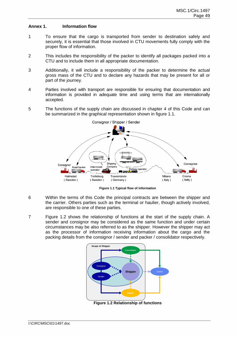
MSC.1/Circ.1497 Page 49
I:\CIRC\MSC\01\1497.doc
Annex 1. Information flow 1 To ensure that the cargo is transported from sender to destination safely and
securely, it is essential that those involved in CTU movements fully comply with the proper flow of information.
2 This includes the responsibility of the packer to identify all packages packed into a CTU and to include them in all appropriate documentation.
3 Additionally, it will include a responsibility of the packer to determine the actual gross mass of the CTU and to declare any hazards that may be present for all or part of the journey.
4 Parties involved with transport are responsible for ensuring that documentation and information is provided in adequate time and using terms that are internationally accepted.
5 The functions of the supply chain are discussed in chapter 4 of this Code and can be summarized in the graphical representation shown in figure 1.1.
Figure 1.1 Typical flow of information
6 Within the terms of this Code the principal contracts are between the shipper and the carrier. Others parties such as the terminal or haulier, though actively involved, are responsible to one of these parties.
7 Figure 1.2 shows the relationship of functions at the start of the supply chain. A sender and consignor may be considered as the same function and under certain circumstances may be also referred to as the shipper. However the shipper may act as the processor of information receiving information about the cargo and the packing details from the consignor / sender and packer / consolidator respectively.
Carrier
Consignor
Shipper
Packer
Consolidator
Scope of Shipper
Sender
Figure 1.2 Relationship of functions

MSC.1/Circ.1497 Page 50
I:\CIRC\MSC\01\1497.doc
7.1 The shipper may also be the packer / consolidator receiving goods from the consignor and packing them into the CTU before despatching it to the carrier.
7.2 Finally the shipper may be the consignor, producing the goods, packing it into the
CTU and then contracting the carrier to move the CTU to its destination. 7.3 There is a final combination, where the shipper combines the consignor, the packer
and the carrier. 8 The shipper will arrange the transport of the goods and may arrange the cargo
insurance cover. In some contracts there is an agreed location, terminal or destination where the responsibility of the shipper ends. Thereafter responsibility is transferred to the consignee or another party who may undertake the function of a shipper.
8.1 Figure 1.3 shows a typical INCOTERM published by the International Chamber of
Commerce. Under this contract the shipper is responsible for all aspects of transport up until the CTU is unloaded at the port of import.
Loadin
g o
n tru
ck
(carr
ier)
Export
custo
ms
decla
ration
Carr
iage to p
ort
of
export
Unlo
adin
g o
f tr
uck
in p
ort
of export
Carr
iage to p
ort
of
export
Loadin
g c
harg
es
in p
ort
of export
Carr
iage to p
ort
of
import
Unlo
adin
g
charg
es in p
ort
of
import
Loadin
g o
n tru
ck
in p
ort
of im
port
Carr
iage to p
lace
of destination
Import
custo
ms
cle
ara
nce
Import
taxes
Shipper Consignee
Insura
nce
DAT Delivered At Terminal
(insert named terminal or place of destination)
Delivery
Figure 1.3 Typical sales contract terms
8.2 Thereafter the consignee, or their agent who will undertake the function of a shipper, will arrange onward transport of the CTU and continue the chain of information for the shipment.

MSC.1/Circ.1497 Page 51
I:\CIRC\MSC\01\1497.doc
Annex 2. Safe handling of CTUs
1 General
1.1 CTUs are designed for intermodal transport. They are capable to be transferred from one mode of transport to another by rolling or lifting. A swap body can be carried on a road vehicle or on a railway wagon. A freight container can be carried on a road vehicle, on a railway wagon, on an inland barge or on a seagoing vessel. A road vehicle can be carried on a railway wagon, on an inland barge or on a seagoing vessel (ro-ro ship). A railway wagon can be carried on a seagoing vessel (railway ferry).
1.2 When CTUs are handled, it should be ensured that all handling devices such as lifting appliances and internal movement equipment are in good condition and suitable for the intended purpose.
1.3 On completion of handling, CTUs should be secured to the means of transport as
appropriate for the specific transport mode. 1.4 A CTU which is leaking cargo or obviously unsafe for further transport should not be
loaded onto a means of transport. 2 Transfer by rolling 2.1 Swap bodies are carried by road on special swap carrier vehicles. The carrier
vehicle is capable to be lowered on its wheels and to roll under the swap body standing on its supports. By lifting the vehicle to its normal operating position, the swap body is taken onto the chassis of the carrier vehicle. Then the support legs are retracted.
2.2 Road vehicles may be rolled onto a ship driven by their own engine. Semi-trailers
are normally carried on board ships without tractor unit. They are loaded to and unloaded from the ships by specific port internal movement vehicles. These vehicles should be conspicuously painted or marked and fitted with a flashing or rotating yellow beacon. The drivers' cab should provide good all round visibility, with minimal obstruction of the driver's view. Only authorized persons should be allowed on the ramp or any vehicle deck while vehicle movements are taking place. The movement of persons on foot on the ramp should be strictly controlled and minimized.
2.3 The cargo decks of railway ferries are equipped with several rail tracks which can be
accessed by a movable ramp which is fitted with rails, capable to be connected to the rail tracks on board. The maximum permissible kink angle between the ramp and the level of the rail deck in the ship is restricted and depends on the type of wagons shunted into the ship. In specific cases this angle may be as low as 1.5°.
3 Transfer by lifting 3.1 Before lifting a CTU, the handling staff should ensure that the lifting equipment is
safely attached to the CTU and that all securing, fixing and lashing devices have been released.
3.2 Swap bodies for combined road/rail transport and also purpose built semi-trailers for
combined road/rail transport are equipped with standardized recesses for being lifted at four points by grappler arms attached to the spreader of a crane or reach stacker. Thus they can be transferred from road to rail and vice versa.

MSC.1/Circ.1497 Page 52
I:\CIRC\MSC\01\1497.doc
3.3 Lifting of freight containers (refer to ISO 3874) 3.3.1 The most appropriate method to lift a freight container is the use of a top lift
spreader. The spreader is locked by twistlocks to the top corner fittings of the freight container. This method can be used for all freight container sizes fitted with top corner fittings, in an empty or packed state. When the spreader cannot be attached directly to the corner fittings, e.g. in case of over-height cargo, slings or chains can be used and connected to the spreader so that the lifting force remains vertical.
3.3.2 The side-lift frame is designed to lift a freight container by the two top corner fittings
of one side and to take the reaction forces on the bottom corner fittings of the same side or on suitable corner post areas above those corner fittings. This method can be used on all sizes of empty freight containers. In the case of packed freight containers, this method is suitable for 20-foot and 10-foot freight containers only.
3.3.3 The end-lift frame is suitable only for the handling of 20-foot and 10-foot empty
freight containers. The frame is designed to lift a freight container by the two top corner fittings of one end and to take reaction forces on the bottom corner fittings of the same end or on suitable corner post areas above those corner fittings.
3.3.4 A top lift sling can be used for empty freight containers of all sizes. The freight
container is lifted by all four top corner castings with forces applied other than vertically. Lifting devices need to be properly engaged, hooks always be placed in an inward to outward direction. In the packed state, this method is suitable only for 10-foot freight containers, provided that the lifting forces are applied at an angle not less than 60° to the horizontal.
3.3.5 A bottom sling is used in connection with a cross beam spreader bar. The freight
container is lifted from the side apertures of four bottom corner fittings by means of slings which are connected to the corner fittings by means of locking devices. Hooks are not suitable for this connection. This method can be used for all freight container sizes in an empty or packed state. For packed freight containers the angle between the sling and the horizontal should not be less than 30° for 40-foot freight containers, 45° for 20-foot freight containers and 60° for 10-foot freight containers.
3.3.6 When a freight container is provided with fork pockets, it can be lifted by means of
forks under certain conditions. The forks should, ideally, extend the whole width of the freight container, but under no circumstances should they extend less than 1,825 mm into the fork pockets. This method can be used on 20-foot and 10-foot freight containers in an empty or packed state with the exception of tanks and pressurized bulk containers which should not be lifted by forklift trucks at all. Where there are no fork pockets, the freight container should not be lifted by forks in any state.
3.4 Railway wagons may be lifted and may change bogies when the railway ferry operates between countries where the gauge of the track is different. In such cases, the railway wagons should be suitable for an easy exchange of bogies. The involved ferry ports provide specific equipment for this operation.
4 Safety and security checks prior to entry
4.1 It is important for the terminal to ensure that CTUs accepted into the terminal are safe for operations and do not present a threat to the safety and security of the terminal, or ships and personnel within its environs. It is particularly important to ensure that "paperless" systems do not result in any dilution of the need to verify documentation.

MSC.1/Circ.1497 Page 53
I:\CIRC\MSC\01\1497.doc
4.2 The terminal should undertake the following actions at the first entry gate of the export yard, or while the CTU is in the terminal and before it goes onto a ship:
Match the carrier's documentation against that of the haulier in order to prevent fraudulent shipments;
Check the integrity of the CTU and its seal in order to preclude stowaways and the smuggling of contraband or threats to security. Whenever a broken or missing seal is found, it should be reported to the shipper and the authorities, and replaced with a new seal. The new seal number should be recorded;
Check the CTU number against documentation;
Check the presence of placards and markings on CTUs containing dangerous goods and verify them against documentation;
Verify the gross mass against documentation by use of a weighbridge or mass gauge/load indicator on yard equipment or, alternatively, verify that accurate gross mass determination has occurred before entry and that such determination was compliant with international requirements, where applicable, or accepted best practice;
Ensure, during the lifting of the CTU by any terminal equipment, that an evaluation is made by the operator to check that the mass of the cargo is reasonably evenly distributed. If it is determined to exceed the "60% within half the length rule", the terminal should take steps to rectify the problem;
Sideline any CTU that appears to be structurally unsound and/or unsafe for a more detailed examination;
Check the lashing of non-enclosed CTUs;
Confirm the dimensions of out of gauge cargo and update booking data accordingly;
Notify the CTU operator if out of gauge cargo is found to be improperly or inadequately secured to the CTU;
Check reefer temperatures against setting and, in cases where the allowable variance is exceeded, follow up with the CTU operator. A reasonable temperature variance should be set to trigger follow up action with CTU operators, and this should vary depending on the cargo type, i.e. chilled or frozen. If this is not possible at the gate due to a low battery, then the check should be made when the CTU is plugged into the terminal's power supply;
Check reefer plugs and wires for defects prior to plugging into the terminal's reefer system.
5 Stacking on ground and terminal operation with freight containers 5.1 The ground should be a firm, flat and drained surface. On the ground, the freight
container should be supported by the four bottom container fittings only. When stacking freight containers, the bottom surfaces of the lower corner fittings of the upper freight container should have complete contact with upper surfaces of top container fittings of the lower freight container. A shift of up to 25 mm laterally and 38 mm longitudinally may be tolerated.

MSC.1/Circ.1497 Page 54
I:\CIRC\MSC\01\1497.doc
5.2 A freight container stack may be subject to forces by heavy wind. This might lead to sliding and toppling of freight containers. Stacks of empty freight containers will be more subject to such dangers than stacks of packed freight containers. The critical wind speed is higher for multiple rows than for a single row. Wind effect can be reduced by limiting the stacking height, by block stowage or by a combination of both. A recommended combination is shown in the table below:
Number of tiers 20-foot standard 40-foot standard 40-foot high cube
2 2 rows 2 rows 3 rows
3 2 rows 3 rows 3 rows
4 2 rows 3 rows 3 rows
5 3 rows 3 rows 4 rows
6 4 rows 4 rows 5 rows
5.3 Above recommendation is applicable for a wind speed up to 20 m/s (8 Bft). In case
of higher wind speeds, additional measures should be considered, such as changing the block to a stepped pyramid or securing freight containers with lashings to the ground.
5.4 Freight containers should be moved within a terminal area only by use of suitable
equipment, such as van carriers, reach stackers or trailers. Trailers should be so constructed that the freight containers are supported by their corner fittings. For operation within the designated terminal area, tie down devices are not required, provided that the freight container is correctly loaded on the trailer and prevented from moving horizontally. Therefore, trailers which are not equipped with twistlocks should be fitted with substantial corner plates or other restraints of sufficient height to retain the freight container in position.
6 Securing of CTUs 6.1 Swap bodies are carried by road on dedicated carrier vehicles. The corner fittings of
the swap body fit onto cones of locking devices (twistlocks) which, by turning the cones, provide a form closure between the swap body and the vehicle structure (see figure 2.1).
Figure 2.1 Twistlock on a road vehicle
6.2 Freight containers should be carried by road on purpose built container chassis, where the freight container is supported by the four corner fittings. The corner fittings of the freight container fit onto the twistlocks cones of the chassis, similar to the securing devices described in 6.1.

MSC.1/Circ.1497 Page 55
I:\CIRC\MSC\01\1497.doc
6.3 When carried by rail, swap bodies and freight containers are loaded on open wagons which are specifically fitted with stacking or locking devices. Semi-trailers may be carried on wagons equipped with dedicated bedding devices for accommodating road vehicles.
6.4 Container vessels are specifically constructed for the carriage of freight containers. Cargo spaces under deck or cargo spaces on hatchless container vessels are equipped with cell guides, where the freight containers are stacked, obtaining sufficient hold and securing. 20-foot freight containers may be stowed in 40-foot cell guides, provided that suitable stacking cones are inserted into the corner fittings of the freight containers. Freight containers carried on deck are affixed to the ships structure by means of twistlocks. Twistlocks are used also to interconnect freight containers stowed one on top of another. In addition, container stacks on deck are secured to the ships structure by means of lashing rods and tensioning devices (bottle screws) (see figure 2.2). Details of the securing arrangement are described in the Cargo Securing Manual of the individual ship.
Figure: 2.2 Cell guides and lashing rods on a container vessel
6.5 When carried on general cargo ships which are not specifically constructed for the carriage of freight containers, the freight containers are secured to the ships structure by means of lashing chains or wire ropes and tensioning devices (see IMO Code of Safe Practice for Cargo Stowage and Securing, Annex 1). Further details are described in the Cargo Securing Manual of the individual ship.
6.6 When vehicles are loaded in a vehicle deck of a ro-ro ship, the parking brakes should be applied and locked, engines should be in gear. Uncoupled semi-trailers should not be supported on their landing legs but preferably supported by a trestle or similar device. Lashings which are attached to the securing points of the vehicle should be connected with hooks or other devices so designed that they cannot disengage from the aperture of the securing point if the lashing slackens during the voyage. Only one lashing should be attached to any one aperture of the securing point on the vehicle. Further details are described in the Cargo Securing Manual of the individual ship.
6.7 The wheels of railcars shunted into the rail deck of a railway ferry should be chocked on the rail with appropriate steel chocks. The wagons should be secured to the ships structure with chains and tensioning devices (bottle screws). In case of severe weather conditions, the spring system of the wagons should be released by use of specific trestles. Further details are described in the Cargo Securing Manual of the individual ship.

MSC.1/Circ.1497 Page 56
I:\CIRC\MSC\01\1497.doc
Annex 3. Prevention of condensation damages 1 Introduction
Condensation damage is a collective term for damage to cargo in a CTU from internal humidity especially in freight containers on long voyages. This damage may materialize in form of corrosion, mildew, rot, fermentation, breakdown of cardboard packaging, leakage, staining, chemical reaction including self-heating, gassing and auto-ignition. The source of this humidity is generally the cargo itself and to some extent timber bracings, pallets, porous packaging and moisture introduced by packing the CTU during rain or snow or packing in an atmospheric condition of high humidity and high temperature. It is therefore of utmost importance to control the moisture content of cargo to be packed and of any dunnage used, taking into consideration the foreseeable climatic impacts of the intended transport.
2 Definitions
For the assessment of the proper state of "container-fitness" of the cargo to be packed and for the understanding of typical processes of condensation damage the most relevant technical terms and definitions are given below:
Absolute humidity of air Actual amount of water vapour in the air, measured in g/m3 or g/kg.
Condensation Conversion of water vapour into a liquid state. Condensation usually starts when air is cooled down to its dew point in contact with cold surfaces.
Corrosion threshold A relative humidity of 40% or more will lead to an increasing risk of corrosion of ferrous metals.
Crypto climate in the container
State of relative humidity of the air in a closed container, which depends on the water content of the cargo or materials in the container and on the ambient temperature.
Daily temperature variation in the container
Rise and fall of temperature in accordance with the times of day and often exaggerated by radiation or other weather influences.
Dew point of air: Temperature below the actual temperature at which a given relative humidity would reach 100%. Example: The dew point of air at a temperature of 30°C and 57% relative humidity (= 17.3 g/m3 absolute humidity) would be 20°C, because at this temperature the 17.3 g/m3 represent the saturation humidity or 100% relative humidity.
Hygroscopicity of cargo Property of certain cargoes or materials to absorb water vapour (adsorption) or emit water vapour (desorption) depending on the relative humidity of the ambient air.
Mould growth threshold A relative humidity of 75% or more will lead to an increasing risk of mould growth on substances of organic origin like foodstuff, textiles, leather, wood, ore substances of non-organic origin such as pottery.
Relative humidity of air Actual absolute humidity expressed as percentage of the saturation humidity at a given temperature. Example: An absolute humidity of 17.3 g/m3 in an air of 30°C represents a relative humidity of 100 · 17.3 / 30.3 = 57%.

MSC.1/Circ.1497 Page 57
I:\CIRC\MSC\01\1497.doc
Saturation humidity of air
Maximum possible humidity content in the air depending on the air temperature (2.4 g/m3 at -10°C; 4.8 g/m3 at 0°C; 9.4 g/m3 at 10°C; 17.3 g/m3 at 20°C; 30.3 g/m3 at 30°C; see figure 3.1 below).
Sorption equilibrium State of equilibrium of adsorption and desorption at a given relative humidity of the ambient air and the associated water content of the cargo or material.
Sorption isotherm An empirical graph showing the relation of water content of a cargo or material to the relative humidity of the ambient air. Usually the adsorption process is used to characterize the above relation. Sorption isotherms are specific for the various cargoes or materials (see figure 3.2 below).
Water content of cargo Latent water and water vapour in a hygroscopic cargo or associated material, usually stated as percentage of the wet mass of cargo (e.g. 20 t cocoa beans with 8% water content will contain 1.6 t water).
0
5
10
15
20
25
30
35
-10 -5 0 5 10 15 20 25 30
Air temperature [°C]
Ab
so
lute
hu
mid
ity [
g/m
3]
- 100
- 90
- 80
- 70
- 60
- 50
- 40
- 30
- 20
- 10
Re
lativ
e h
um
idity
[%]
Figure 3.1 Absolute and relative humidity
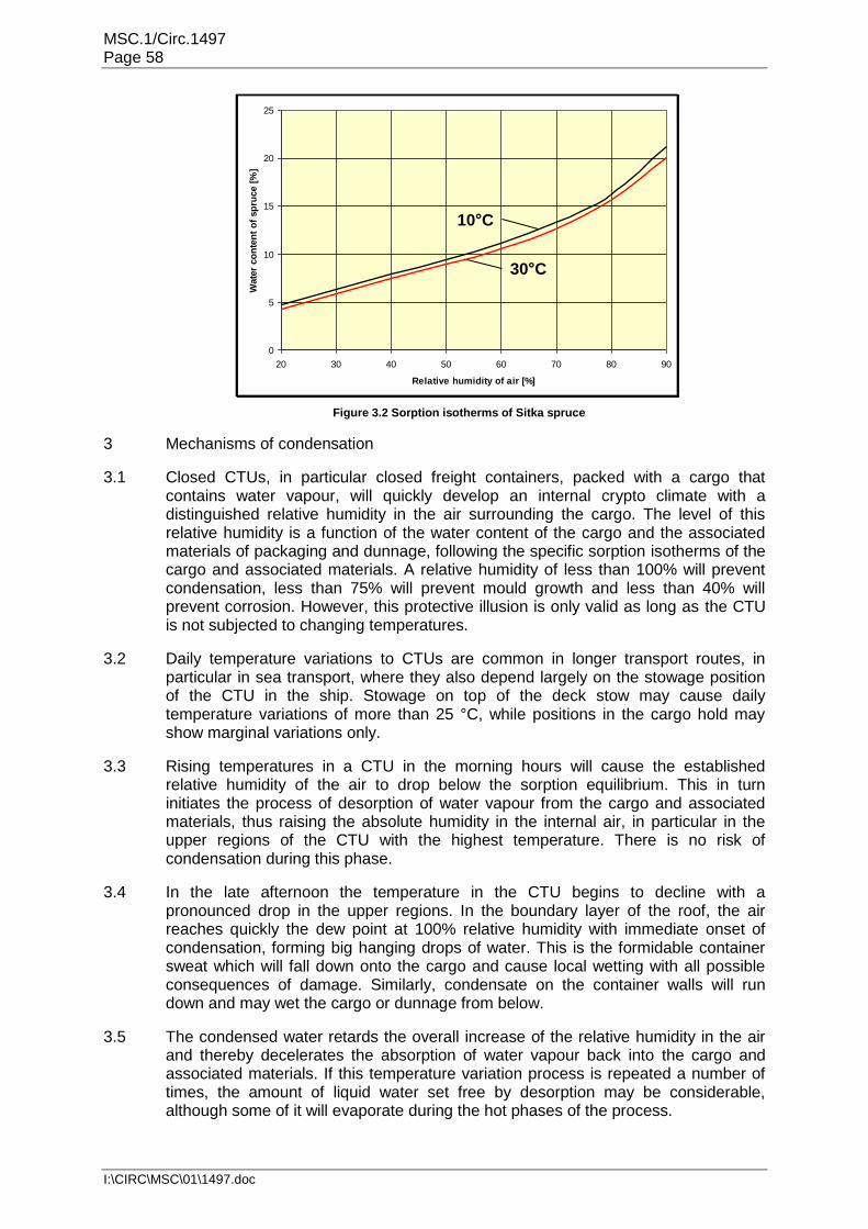
MSC.1/Circ.1497 Page 58
I:\CIRC\MSC\01\1497.doc
0
5
10
15
20
25
20 30 40 50 60 70 80 90
Relative humidity of air [%]
Wate
r co
nte
nt
of
sp
ruce [
%]
10 C
30 C
Figure 3.2 Sorption isotherms of Sitka spruce
3 Mechanisms of condensation
3.1 Closed CTUs, in particular closed freight containers, packed with a cargo that contains water vapour, will quickly develop an internal crypto climate with a distinguished relative humidity in the air surrounding the cargo. The level of this relative humidity is a function of the water content of the cargo and the associated materials of packaging and dunnage, following the specific sorption isotherms of the cargo and associated materials. A relative humidity of less than 100% will prevent condensation, less than 75% will prevent mould growth and less than 40% will prevent corrosion. However, this protective illusion is only valid as long as the CTU is not subjected to changing temperatures.
3.2 Daily temperature variations to CTUs are common in longer transport routes, in particular in sea transport, where they also depend largely on the stowage position of the CTU in the ship. Stowage on top of the deck stow may cause daily temperature variations of more than 25 °C, while positions in the cargo hold may show marginal variations only.
3.3 Rising temperatures in a CTU in the morning hours will cause the established relative humidity of the air to drop below the sorption equilibrium. This in turn initiates the process of desorption of water vapour from the cargo and associated materials, thus raising the absolute humidity in the internal air, in particular in the upper regions of the CTU with the highest temperature. There is no risk of condensation during this phase.
3.4 In the late afternoon the temperature in the CTU begins to decline with a pronounced drop in the upper regions. In the boundary layer of the roof, the air reaches quickly the dew point at 100% relative humidity with immediate onset of condensation, forming big hanging drops of water. This is the formidable container sweat which will fall down onto the cargo and cause local wetting with all possible consequences of damage. Similarly, condensate on the container walls will run down and may wet the cargo or dunnage from below.
3.5 The condensed water retards the overall increase of the relative humidity in the air and thereby decelerates the absorption of water vapour back into the cargo and associated materials. If this temperature variation process is repeated a number of times, the amount of liquid water set free by desorption may be considerable, although some of it will evaporate during the hot phases of the process.

MSC.1/Circ.1497 Page 59
I:\CIRC\MSC\01\1497.doc
3.6 A quite similar mechanism of condensation may take place if a freight container with a warm and hygroscopic cargo, e.g. coffee in bags, is unloaded from the ship but left unopened for some days in a cold climate. The cargo will be soaked by condensation from the inner roof of the freight container.
3.7 Notwithstanding the above described risk of container sweat due to the daily
temperature variation, an entirely different type of condensation may take place if cargo is transported in a closed CTU from a cold into a warm climate. If the CTU is unpacked in a humid atmosphere immediately after unloading from the vessel, the still cold cargo may prompt condensation of water vapour from the ambient air. This is the so-called cargo sweat, which is particularly fatal on metal products and machinery, because corrosion starts immediately.
4 Loss prevention measures 4.1 Corrosion damage: Ferrous metal products, including machinery, technical
instruments and tinned food should be protected from corrosion either by a suitable coating or by measures which keep the relative humidity of the ambient air in the CTU reliably below the corrosion threshold of 40%.
4.2 The moisture content of dry dunnage, pallets and packing material can be estimated
as 12% to 15%. The sorption isotherms for those materials show that with this moisture content the relative humidity of the air inside the CTU will inevitably establish itself at about 60% to 75% after closing the doors. Therefore additional measures like active drying of the dunnage and packing material or the use of desiccants (drying agents in pouches and other passive methods for moisture capture) should be taken, in combination with a sealed plastic wrapping.
4.3 Fibreboard packaging and dunnage when used in association with dangerous goods
should undergo water resistance test using the Cobb method as specified in ISO 53513.
4.4 Mould, rot and staining: Cargoes of organic origin, including raw foodstuff, textiles,
leather, wood and wood products, or substances of non-organic origin such as pottery, should be packed into a CTU in "container-dry" condition. Although the mould growth threshold has been established at 75% relative humidity, the condition "container-dry" defines a moisture content of a specific cargo that maintains a sorption equilibrium with about 60% relative humidity of the air in the CTU. This provides a safety margin against daily temperature variations and the associated variations of relative humidity. Additionally, very sensitive cargo should be covered by unwoven fabric (fleece) which protects the cargo top against falling drops of sweat water. The introduction of desiccants into a CTU containing hygroscopic cargo, that is not "container-dry", will generally fail due to the lack of sufficient absorption capacity of the drying agent.
4.5 Collapse of packing: This is a side effect of moisture adsorption of usual cardboard
that is not waterproof. With increasing humidity from 40% to 95% the cardboard loses up to 75% of its stableness. The consequences are the collapse of stacked cartons, destruction and spill of contents. Measures to be taken are in principle identical to those for avoiding mould and rot, or the use of "wet strength" cardboard packaging.
13 EN 20535:1994, ISO 535:1991 Paper and board - Determination of water absorptiveness - Cobb method

MSC.1/Circ.1497 Page 60
I:\CIRC\MSC\01\1497.doc
4.6 Unpacking 4.6.1 Goods packed in a cold climate on arrival in a warm climate with higher absolute
humidity should be delayed until the goods have warmed up sufficiently for avoiding cargo sweat. This may take a waiting time of one or more days unless the goods are protected by vapour tight plastic sheeting and a sufficient stock of desiccants. The sheeting should be left in place until the cargo has completely acclimatized.
4.6.2 Hygroscopic goods packed in a warm climate on arrival in a cold climate with low
absolute humidity should be unpacked immediately after unloading from the vessel, in order to avoid cargo damage from container sweat. There may be a risk of internal cargo sweat when the cargo is cooled down too quickly in contact with the open air, but experience has shown that the process of drying outruns the growth of mould, if the packages are sufficiently ventilated after unpacking
.

MSC.1/Circ.1497 Page 61
I:\CIRC\MSC\01\1497.doc
Annex 4. Approval plates
1 Safety plates
1.1 Freight containers used in international transport and, under certain conditions, also swap bodies and road trailers are required by applicable regulations to bear safety approval plates.
1.2 Under the International Convention for Safe Containers (CSC), each freight container is required to bear a safety approval plate permanently affixed to the rear of the freight container, usually the left hand door. On this plate, the most important information for the packer is:
The date manufactured;
The maximum gross mass14; and
The allowable stacking mass14,
as shown in figure 4.1.
DATE MANUFACTURED
IDENTIFICATION NO.
ALLOWABLE STACK WT FOR 1.8G
MAXIMUM GROSS MASS
RACKING TEST LOAD VALUE
MM/YYYY
XXXX / YY / 123456
34,000 KGS 74,960 LBS
216,000 KGS 476,190 LBS
15,240 KGS 33,600 LBS
D-HH-3000 / GL 6000
CSC SAFETY APPROVAL
Figure 4.1 Diagram of CSC safety approval plate
1.2.1 The CSC requires freight containers to be thoroughly examined 5 years after
manufacture and subsequently at least every 30 months. The date of the next periodic examination is stamped on the approval plate or affixed to it in form of a decal (see figure 4.2).
Figure 4.2 CSC safety approval plate with next examination date
1.2.2 As an alternative to such periodic inspections, the owner or operator of the freight
container may execute an approved continuous examination programme where the freight container is frequently inspected at major interchanges. Freight containers operated under such programme should be marked on or near to the safety approval plate with a mark starting "ACEP" followed by numerals and letters indicating the approval number of this continuous examination programme (see figure 4.3).
14 The maximum gross mass and the maximum allowable stacking mass (allow. stack. wt.) should not be
exceeded.
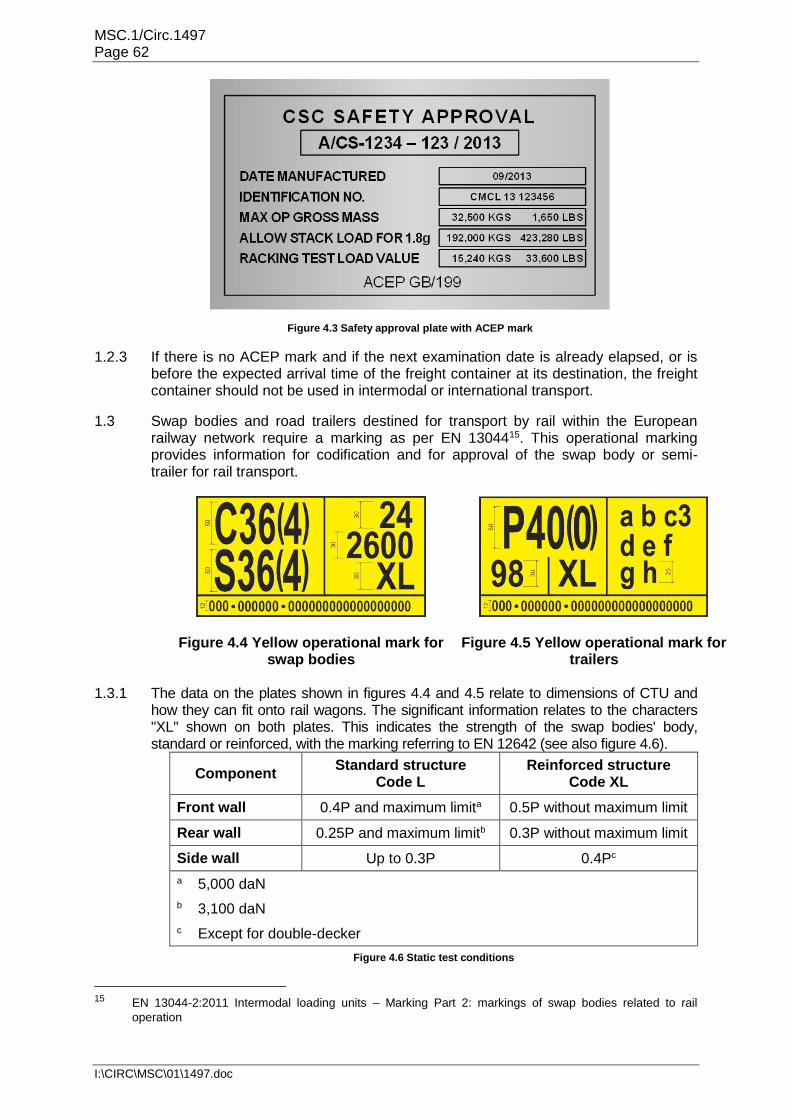
MSC.1/Circ.1497 Page 62
I:\CIRC\MSC\01\1497.doc
Figure 4.3 Safety approval plate with ACEP mark
1.2.3 If there is no ACEP mark and if the next examination date is already elapsed, or is before the expected arrival time of the freight container at its destination, the freight container should not be used in intermodal or international transport.
1.3 Swap bodies and road trailers destined for transport by rail within the European railway network require a marking as per EN 1304415. This operational marking provides information for codification and for approval of the swap body or semi-trailer for rail transport.
Figure 4.4 Yellow operational mark for swap bodies
Figure 4.5 Yellow operational mark for trailers
1.3.1 The data on the plates shown in figures 4.4 and 4.5 relate to dimensions of CTU and
how they can fit onto rail wagons. The significant information relates to the characters "XL" shown on both plates. This indicates the strength of the swap bodies' body, standard or reinforced, with the marking referring to EN 12642 (see also figure 4.6).
Component Standard structure
Code L Reinforced structure
Code XL
Front wall 0.4P and maximum limita 0.5P without maximum limit
Rear wall 0.25P and maximum limitb 0.3P without maximum limit
Side wall Up to 0.3P 0.4Pc
a 5,000 daN
b 3,100 daN
c Except for double-decker
Figure 4.6 Static test conditions
15 EN 13044-2:2011 Intermodal loading units – Marking Part 2: markings of swap bodies related to rail
operation

MSC.1/Circ.1497 Page 63
I:\CIRC\MSC\01\1497.doc
1.3.2 The XL test requirements specifically apply to the following types of body structures:
box type;
drop side with side and tail boards without cover;
drop side with side and tail boards with tarpaulin cover;
curtain-siders.
2 Maximum gross mass 2.1 Freight containers, like all CTUs, have a maximum gross operating mass or rating
which is shown both on the CSC safety approval plate (see figures 4.1, 4.2 and 4.3) and on the rear end of the freight container (see figure 4.7).
Figure 4.7 Rear of freight container
2.2 The two values shown on a freight container should be the same, however if they
are different the value shown on the CSC safety approval plate should be used. 2.3 The tare mass shown in the figure relates to the empty mass of the freight container
and should always be shown on the rear end of the freight container. This value will include any permanently attached equipment such as an integral refrigeration unit, but will not include items that are attached, such as a nose mounted generator (clip on unit).
2.4 The maximum payload (or net mass) may be shown on the rear of the freight
container, however the correct method for calculating the maximum mass of cargo that the freight container can carry is:
Where: P Maximum payload (or net mass) of
cargo R Maximum gross mass of freight
container Tc Tare mass of the freight container Tg Mass of additional attached items Ts Mass of the securing and bracing
materials 3 Allowable stacking mass 3.1 The allowable stacking mass represents the maximum superimposed load that any
freight container can be subjected to and is often referred to as the stacking capability or stack height (when converted to a number of freight containers).
P = R – (Tc +Tg + Ts)

MSC.1/Circ.1497 Page 64
I:\CIRC\MSC\01\1497.doc
3.2 Freight containers built to the provisions of ISO 1496 are required to withstand a minimum superimposed load of 192,000kg. This value is the equivalent of eight superimposed freight containers with an average mass of 24,000kg.
3.3 Freight containers having an allowable stacking mass of less than 192,000 kg are not unrestrictedly suitable for sea transport. This includes:
Freight containers built to a previous standard;
Swap bodies;
Freight containers designed to be used with one door removed/open.
3.4 Swap containers and tanks have a different design and therefore a different stacking capability. The wider designed width of the swap bodies means that there is a step between the corner posts and the top corner fittings which are shown clearly on the swap tank as shown in figures 4.8 and 4.9.
Figure 4.8 Step back at the top fitting
Figure 4.9 Step back with secondary side lift aperture
3.5 Freight containers with a step of this nature will generally have a lower stacking capability. The freight container may be marked with a warning decal that indicates that there is a reduced stacking capability.
3.6 Freight containers with one door off / open will have reduced allowable stacking mass and racking as shown in figure 4.10.
Figure 4.10 CSC safety approval plate for one door off operation
3.7 The practice of transporting cargo in one door open or one door removed freight containers is inherently dangerous and therefore is strongly discouraged. The practice is illegal unless it is marked on the CSC plate (see figure 4.10). Additionally, there may be negative consequences to using this practice in the supply chain (e.g. terminals refusing to handle open door freight containers).
3.8 Where there is reduced allowable stacking mass, due to design or operation, the total gross mass of freight containers and swap bodies placed above should not exceed this value.
3.9 Freight containers which are designed with an allowable stacking mass less than 192,000 kg should be marked in accordance with ISO 6346. This means that the fourth character of the ISO size type code will be a letter.

MSC.1/Circ.1497 Page 65
I:\CIRC\MSC\01\1497.doc
4 Tank data plates 4.1 All tank containers and swap tanks require essential manufacturing and test data to
be recorded on a data plate. This will be generally found on the rear of the tank but may be found attached to the side of one of the rear corner posts.
4.2 The plate shown in figure 4.11 is a typical tank data plate with the sections identified.
Figure 4.11 Typical tank data plate
Owner's name and address
Manufacturers name, address and manufacturing serial number
Tank design details
Operation details
Pressures
Materials
Connections
Inspecting authority
Hydraulic test data
Timber content
CSC safety approval plate
Customs plate
4.3 The important sections are the CSC safety approval plate and the hydraulic test
data. Every tank should be subjected to a pressure test every 30 months and a full hydraulic test every 5 years and the date of the test marked on the data plate.
5 European rail wagon marks 5.1 Static axle load and linear load 5.1.1 The axle load and axle spacing of the vehicles defines the vertical quasi-static load
input to the track. 5.1.2 The load limits for wagons take into account their geometrical characteristics,
weights per axle and weights per linear metre. 5.1.3 They should be in accordance with the classification of lines or sections of lines,
categories A, B1, B2, C2, C3, C4, D2, D3, D4 as defined in the following table.
Classification Mass per axle (P)
A B C D E F G
Mass per unit length (p) 16.0 t 18.0 t 20 t 22.5 t 25.0 t 27.5 t 30.0 t
5.0 t / m A B1
6.4 t / m B2 C2 D2
7.2 t / m C3 D3

MSC.1/Circ.1497 Page 66
I:\CIRC\MSC\01\1497.doc
8.0 t / m C4 D4 E4
8.8 t / m E5
10.0 t / m
p = Mass per unit length, i.e. the wagon mass plus the mass of the load, divided by the wagon length in metres, measured over the buffers when uncompressed.
P = Mass per axle
5.1.4 Classification according to the maximum mass per axle P is expressed in capital letters (A, B, C, D, E, F, G); classification according to the maximum mass per unit length p is expressed in Arabic numerals (1, 2, 3, 4, 5, 6), except for Category A.
5.1.5 Rail vehicle load table Shown on each side to the left The maximum payload is generally not a fixed value for the distinguished wagon, but
allocated case by case by means of the intended track category (categories A, B, C, D) and the speed category (S: ≤ 100 km/h; SS: ≥ 120 km/h). These payload figures imply a homogeneous load distribution over the entire loading area (see figure 4.12).
Figure 4.12 Allocation of payload to a rail car
5.1.6 Concentrated loads Shown in the centre of each solebar16
In case of concentrated loads a reduction of the payload is required, which depends
on the loaded length and the way of bedding the concentrated load. The applicable load figures are marked in each wagon. Also any longitudinal or transverse eccentricity of concentrated loads is limited by the individual axle load capacity or the wheel load capacity (see figure 4.13).
16 Main side beam of a rail wagon.

MSC.1/Circ.1497 Page 67
I:\CIRC\MSC\01\1497.doc
d dc cb a ba
a – a 2 32.0 33.0
b – b 5 39.0 44.0
c – c 9 42.0 52.0
d – d 15 52.0 65.5
m t
Column Symbol Description
1
Signs showing the length of the supporting surfaces of concentrated loads, or the distance between supports
2 m Distance in metre between the signs showing the length
3 Maximum tonnage of concentrated loads
4 Maximum tonnage of loads resting on two supports
Figure 4.13 Reduction in payload due to concentrated load and bedding distance

MSC.1/Circ.1497 Page 68
I:\CIRC\MSC\01\1497.doc
Annex 5. Receiving CTUs 1 Introduction 1.1 This annex covers a number of actions and activities and
provides safety advice for persons involved in the reception and unpacking of CTUs.
1.2 When receiving a CTU, the receiver or consignee should: 1.2.1 Confirm that the unit is as specified on the transport
documentation, checking the CTU identification reference as shown in figure 5.1. If the identification reference shown on the documentation is not the same as that on the CTU, it should not be accepted until clarification is received from the shipper.
Figure 5.1 Three examples of CTU identification references
1.2.2 Inspect the seal, if fitted. Inspecting a seal requires visual check for signs of
tampering, comparison of the seal's identification number with the cargo documentation, and noting the inspection in the appropriate documentation. If the seal is missing, or shows signs of tampering, or shows a different identification number than the cargo documentation, then a number of actions are necessary:
1.2.3 The receiver or consignee should bring the discrepancy to the attention of the carrier
and the shipper. The consignee should also note the discrepancy on the cargo documentation and notify Customs or law enforcement agencies, in accordance with national legislation. Where no such notification requirements exist, the consignee should refuse custody of the CTU pending communication with the carrier until such discrepancies can be resolved.
2 Positioning CTUs 2.1 Wheeled operation 2.1.1 Road trailers and freight containers on chassis can be left at the packer's premises
for a period of time without a tractor unit. When this happens, the correct positioning of the CTU is particularly important as a safe shifting of the CTU at a later stage might be difficult. After positioning, brakes should be applied and wheels should be chocked.
2.1.2 Trailers with end door openings and general purpose freight containers on chassis
can be backed up to an enclosed loading bay or can be positioned elsewhere in the premises. For this type of operation a safe access to the CTU by means of suitable ramps is required.
ILU-Code Identification
Reference
Trailer Identification
Reference
Container Identification
Reference

MSC.1/Circ.1497 Page 69
I:\CIRC\MSC\01\1497.doc
2.1.3 When a semi-trailer or a freight container on a chassis is to be packed, care should be taken to ensure that the trailer or chassis cannot tip while a lift truck is being used inside the CTU (see figure 5.2).
Figure 5.2 Inadequate support of a trailer
If there is a risk for forward tipping the semi-trailer or chassis should be sufficiently supported by fixed or adjustable supports (see figures 5.3 and 5.4).
Figure 5.3 Fixed support
Figure 5.4 Adjustable support
2.2 Grounded operation 2.2.1 Freight containers may be unloaded from the delivery vehicle and be placed within
secure areas for packing. The area should be level and have a firm ground. Proper lifting equipment is required.
2.2.2 When landing freight containers it should be ensured that the area is clear of any
debris or undulations in the ground that may damage the understructure (cross members or rails) of the freight container.
2.2.3 As freight container doors may not operate correctly when the ground is not level,
the door end of the freight container should be examined. When one corner is raised off the ground, when the doors are out of line (see figure 5.5) or when the anti-racking plate is hard against one of the stops, the freight container doors should be levelled out by placing shims under one or other corner fitting, as appropriate.
Figure 5.5 Racked freight container

MSC.1/Circ.1497 Page 70
I:\CIRC\MSC\01\1497.doc
2.2.4 When a swap body standing on its support legs is to be packed, particular care should be taken to ensure that the swap body does not tip when a lift truck is used for packing. It should be checked that the support legs of the swap body rest firmly on the ground and cannot shift, slump or move when forces are exerted to the swap body during packing (see figure 5.6).
Figure 5.6 Swap body landed on support legs
2.3 Access to the CTU 2.3.1 After the CTU has been positioned for packing, a safe access should be provided.
For loading a CTU by means of forklift trucks driven into the CTU, a bridging unit between the working ground or loading ramp and the CTU floor should be used. The bridging unit should have lateral boundaries and be safely connected to the CTU for avoiding dislocation of the bridging unit during driving operations.
2.3.2 If the CTU floor is at a height level different to that of the loading ramp, a hump may
appear between the loading ramp and the bridging unit or between the bridging unit and the CTU floor. Care should be taken that the forklift truck used keeps sufficient ground clearance over this hump. Lining the level differences with suitable timber material under the bridging unit should be considered (see figures 5.7 and 5.8).
Figure 5.7 Grounding on down slope
Figure 5.8 Grounding on up slope
2.3.3 If forklift trucks are employed for packing, any roofs or covers of the CTU should be opened if necessary. Any movable parts of such roofs or covers should be removed or suitably secured in order to avoid interference with the loading procedure.
2.4 Packing of CTUs in poor daylight conditions may require additional lighting. Electric lighting equipment should be used under the strict observance of relevant safety regulations, in order to eliminate the risk of electric shocks or incentive sparks from defective cables or heat accumulation from light bulbs.
3 Removing seals
3.1 Stance
3.1.1 The height of the door handle and the seal varies depending on the type of CTU and the design of the door. Rigid vehicles and trailers are generally lower within a range of

MSC.1/Circ.1497 Page 71
I:\CIRC\MSC\01\1497.doc
1.1 and 1.6 m from the ground. Freight containers carried on a trailer will have the security cam fitted seal approximately 1.4 m from the ground, but the handles and any seals attached to them at a height of approximately 1.9 m (see figures 5.9 and 5.10).
≈1.1m
≈1.6m
Figure 5.9 Seal heights - trailer
≈1.4m≈1.9m
Figure 5.10 Seal heights - freight container
3.1.2 Seals attached to handles on container doors (approximately 1.9 m above the
ground) will be about head height for the average person and attempting to cut through a bolt seal at that height is likely to result in a musculoskeletal injury.
3.1.3 The best posture for cutting seals is for the operator to stand upright with the angle at
the elbow between 90° and 120° and the elbow in line or slightly forward of the body. 3.1.3.1 Avoid positions where the elbows are behind the body or above the shoulder. 3.1.3.2 When gripping the cutting tool, the wrist should be kept as straight as possible. 3.1.3.3 The best position of the cutting head will be
approximately 0 to 15 cm above the height of the elbow. The height above ground level to the elbow for the average (western) man is 109 cm. This means that the best position for the seal will be between 109 and 124 cm (1.09 and 1.24 m) above standing level.
3.1.4 Figure 5.11 shows a typical example of how many seals are actually cut. The operator has his back bent, the seal is well below the height of the elbow, the arms are almost straight and the left wrist is cocked, while the right appears to be straight.
3.1.5 The length of the bolt cutter levers are very long compared to the movement of the cutting blades, therefore the hands have to "squeeze" in a considerable distance.
3.1.6 Cutting resistance is high as the blades start to cut and reduces to grow again as the cut finishes. Therefore while the hands are wide apart the greatest inwards pressure is required.
3.2 Height adjustment
3.2.1 The normal height for the seals above ground level is between 1.09 and 1.24 m. This means that a normal person when cutting the lower seal position of a freight container mounted on a trailer and with an ideal stance would have their feet approximately 16 cm above ground level. For the higher seal position the foot position would be about 50 cm above the ground.
Figure 5.11 Cutting the seal

MSC.1/Circ.1497 Page 72
I:\CIRC\MSC\01\1497.doc
3.2.2 It is essential that the operator is able to gain a firm footing when cutting the seal. This may require the legs to be spread both laterally and longitudinally. The footing should be:
Non-slip;
Level;
Free from debris and loose items.
There should also be no trip hazard or risk of the operator falling. 3.2.3 For cutting the seal at the lower position a single pallet with a plywood panel fixed to
the top, or two pallets stacked with a plywood panel, all fixed together so that there is no risk of the items sliding independently would provide a suitable platform. However there is a risk of the operator accidentally falling from the platform during the cutting operation.
3.2.4 To access the highest seals, the use of a
proprietary platform with a narrow work platform width may not allow the operator to stand comfortably and safely as the depth may not be sufficient. A second platform with a plywood panel fixed to both will allow sufficient area for the operator to stand and operate the bolt cutters safely (see figure 5.12). Such platforms should also be fitted with fall protection by way of barriers.
3.2.5 Mobile work platforms similar to the one shown in figure 5.13 may be rather more sophisticated than is required and a smaller version may be more appropriate (see figure 5.14). As an alternative a simpler device can be fitted to the tines of a forklift truck as shown in figure 5.15.
Figure 5.13 Mobile work platform
Figure 5.14 Mobile work device
Figure 5.15 Mobile work station
3.2.6 The important feature of a mobile work platform is that it can be adjusted to exactly
the correct height, has a platform of sufficient area and provides the operator with full fall protection.
3.2.7 A ladder can be used, but this is not a really suitable platform for cutting with large
bolt cutters. For smaller cutters they may be used with care.
Figure 5.12 Work platform

MSC.1/Circ.1497 Page 73
I:\CIRC\MSC\01\1497.doc
3.2.7.1 When carrying out a task using a ladder or a step ladder it is essential that three points of contact (hands and feet) are maintained at the working position. Since both hands are required to cut the seal using the bolt cutters, the third point of contact can be substituted by leaning the chest on the ladder or step ladder.
3.2.7.2 Working on a ladder or step ladder should not involve any side loading which
necessitates twisting of the body, therefore it is improbable that a ladder can be positioned so as to comply with these requirements and provide sufficient room for the bolt cutters to be operated correctly.
3.2.7.3 Therefore if there is a choice only between a ladder and a step ladder the step
ladder will probably provide the better work position. 3.2.8 Figure 5.16 shows the correct position for the operator with the bolt cutters held
between the step ladder and the CTU. 3.2.9 In this position there is still a risk of the ladder falling sideways as the cutters are
squeezed in, therefore the operator should be supported by a co-worker or the step ladder secured to prevent it falling or sliding.
3.2.10 A safer solution is to use wide mobile steps with a top platform sufficiently wide and
deep to permit the operator to stand safely.
4 Preparing to open the doors 4.1 External checks 4.1.1 Once the seal has been removed the CTU doors may be opened, however before
doing so, a few more checks should be made. 4.1.1.1 Check the exterior for signs, marks or other labels that may indicate that the cargo
may put those involved in unpacking the CTU at risk.
Figure 5.16 Working on container doors

MSC.1/Circ.1497 Page 74
I:\CIRC\MSC\01\1497.doc
Figure 5.17 Flexitank label
Figure 5.18 Fumigation label
Figure 5.19 Dangerous
atmosphere label
4.1.1.2 The labels shown above indicate that opening the doors should follow a particular
process. Only the right hand door on a CTU carrying a flexitank should be opened (see figure 5.17). CTUs that have been fumigated (see figure 5.18) or where there is a coolant or conditioner (see figure 5.19) should be opened and ventilated before entering the CTU.
4.1.2 Dangerous atmospheres 4.1.2.1 CTUs carrying dangerous goods also should be opened with care as there is a risk
that the carrying packages have been damaged and the goods spilled. 4.1.2.2 Fumigants are highly toxic. Cargoes most likely to have been fumigated include
foodstuffs, leather goods, handicrafts, textiles, timber or cane furniture, luxury vehicles and cargo in timber cases or on timber pallets.
4.1.2.3 CTUs transported under fumigation are required to be marked and declared in
accordance with the applicable dangerous goods regulations. However, absence of marking cannot be taken to mean fumigants are not present. CTUs marked as having been ventilated after fumigation may also contain fumigant that was absorbed by the cargo and released during transit (see annex 9).
4.1.2.4 CTUs that are fumigated should be properly marked.
On occasion, marks may become obliterated or lost during transport. As CTUs may then not be appropriately marked, the doors and vents should be checked. Tape applied to door gaskets or to the vents may indicate the risk of fumigant presence (see figure 5.20).
4.1.2.5 In addition to the presence of fumigants, toxic gases
associated with the cargo's manufacturing process have been found in dangerous levels, for example shoes may have high levels of toluene, benzene and 1,2-dichloroethane.
4.1.2.6 In the short term, vapours irritate the eyes, the skin and respiratory tract. Inhalation
of vapours can cause pulmonary oedema. The substance can have an effect on the central nervous system, the kidneys and the liver, causing functional deficiency.
Figure 5.20 Vent tapped over

MSC.1/Circ.1497 Page 75
I:\CIRC\MSC\01\1497.doc
4.1.3 If there are concerns that there are signs of a dangerous atmosphere, a safety data sheet (SDS) should be requested from the consignor or from the shipper, as appropriate and sampling the air inside the CTU before opening could be considered.
5 Measuring gases 5.1 A number of surveys have revealed undeclared gases carried in CTUs. Many of the
gases are dangerous and would constitute a severe risk to those involved in unpacking.
5.2 The person who controls the opening and entry of CTUs should always check the
chemical properties and the threshold limit value (TLV) of the relevant chemical, referring to their own national standards and guidelines where they exist.
5.3 Unfortunately, one cannot rely on ones sense of smell as most of these gases will
be well above their TLV by the time they can be detected. The only practical way is to take air samples. In the open this is very difficult. Initially, a device that identifies the gas is required before the concentration of the gas can be measured.
5.4 The simplest and easiest way to measure the
internal atmosphere is to use a readily available detector tube device. Do not open the CTU but gas can be sampled by forcing a solid tube in through the door gaskets (see figure 5.21).
5.5 There is no device available that can detect all
hazardous gases, therefore one measurement will not provide sufficient information about the internal atmosphere and multiple tests will be required.
5.6 The risk of hazardous gases in CTUs is relevant to all parties in the supply chain. The causes of these gases can be attributed to internal business processes in manufacturing or by actions performed on behalf of third parties (service providers and logistics companies).
5.7 Action plans for testing and reacting to hazardous gases in CTUs may be drawn up
by companies to protect their employees from the effects of these gases when opening and unpacking them. The companies producing the actions plans may not be the ultimate consignees of the goods, but may be authorized to open the CTU earlier in the supply chain or responsible for unpacking.
5.8 It should be remembered that hazardous gases may be introduced into the CTU by:
Deliberately adding gases to prevent deterioration of the goods by pests;
Emissions of substances used in the manufacture of products or dunnage;
Chemical or other processes in the cargo.
5.9 In addition, incidents may occur that permit the release of gases from declared or undeclared dangerous goods being carried.
Figure 5.21 Sampling gas

MSC.1/Circ.1497 Page 76
I:\CIRC\MSC\01\1497.doc
6 Opening the doors 6.1 Unstable or poorly packed cargoes may be pressing against the doors which may
be forced open when the door gear is released, or the cargo may fall out once the doors are opened.
6.2 The first action for steel doors is to "ring" them which is to tap the flat surface of both
doors. If the sound is dull and there is no resonance then it is likely that the cargo will be resting against the door. Extra care should be taken when opening the door.
6.3 If there is a risk that the cargo is resting against the
doors or the CTU contains bulk materials, a safety chain can be fitted across the doors, from top to bottom corner fittings (see figure 5.22). This technique can be also used on CTUs without corner fittings by applying a chain from an anchor point on each side or using a shorter chain attached to the locking bars. The length of the chain should be long enough to permit the doors to open but short enough so that the doors cannot open more than 150 mm (6 in).
6.4 If a diagonal chain cannot be fitted, then a loose strap
across the inner lock rods may be used. If there is no facility for attaching the strap, or strap available the person opening the doors should always open the doors with caution.
6.5 Handles for CTUs vary, some will have one locking bar, others two and the handle
design may be a bar or a formed handle, as shown in figures 5.23 to 5.25.
Figure 5.23 Container doors
Figure 5.24 Trailer doors
Figure 5.25 Trailer doors
6.6 They may be in the format where the handle is on the same side of the locking rod
(see figure 5.26) or between the rods (see figure 5.27).
Figure 5.22 Safety chain

MSC.1/Circ.1497 Page 77
I:\CIRC\MSC\01\1497.doc
Figure 5.26 Handles on same side
Figure 5.27 Handles between bars
6.7 Most CTU doors open easily by rotating the handles approximately 90° and then
pulling on the handles of locking bars. The action of rotating the bars will mean that the cams push against their keepers and force the door open.
6.8 Figure 5.28 shows the operation of the cams on
many freight containers. Rotating the lock rod (A) will
cause the breaker surface of the cam to press
against the keeper (B), thus forcing the door open(C).
6.9 Once the lock rods have been fully rotated, adopt an upright stance and grasp the lock rods or the door at about shoulder height or just below and pull backwards using the whole body.
6.10 If the doors do not open easily:
Check that the cams are clear of the keepers;
Check that the CTU is level and the doors are not binding on the frame;
Gain assistance to pull the doors open.
6.11 If one door will not open, and the other door may be opened (i.e. the CTU is not carrying a dry bulk tank), then both doors could be opened at the same time which may make opening the doors easier.
6.12 As the door opens be prepared to step back quickly if:
The contents of the CTU start to fall out; or
The door appears to be pushing you, not you pulling the door.
6.13 If you need to step out of the way move away from the hinged side of the door.
6.14 Doors in the various types of CTU may open with different degrees of difficulty. The following contribute to this difficulty:
Corrosion to the door component and hinge pins;
Damage to the door component, including door gear, or corner post resulting in the misalignment of the hinges;
Condition of the gaskets, which may not seat properly on the door;
Racking of the CTU. Many CTUs rely on the doors to hold the rear end of the CTU square. If the CTU is placed on uneven ground the CTU may rack and the doors become misaligned (see figure 5.29).
A
C
B
Figure 5.28 Door cam operation

MSC.1/Circ.1497 Page 78
I:\CIRC\MSC\01\1497.doc
6.15 Once the doors are free to swing and there is no risk on injury caused by the cargo
falling out, walk the doors through 270° and attach the retaining strap to the hook to prevent the door from swinging (see figure 5.30).
Figure 5.29 Racked CTU
Figure 5.30 Door retaining strap
6.16 DO NOT ENTER THE CTU YET 7 Ventilation 7.1 Introduction 7.1.1 Closed CTUs are enclosed spaces and care should be taken before entering. Even
without toxic gases and other asphyxiates oxygen supply may be depleted which could make normal breathing difficult. Ventilating a CTU will allow fresh air to circulate into the CTU and around any cargo carried and remove any harmful or toxic gases or fumes. The most effective method is to use forced ventilation.
7.1.2 It is a risky activity and it is important that CTUs are ventilated responsibly. The
person who opens and closes the doors should be aware of the possible risks involved and, if required, wear personal protective equipment (PPE). The selection of the appropriate PPE will depend on measurements taken to determine the concentration and toxicity of the gases within the CTU and may require a combination of breathing apparatus and skin protection.
7.2 Planning 7.2.1 When ventilating CTUs a number of factors will determine the action required: 7.2.1.1 The concentration of the gas. The greater the concentration the longer the CTU will
require for ventilation. 7.2.1.2 The nature of the gas. Some gases are very light and volatile and will evaporate
quickly. Others are less volatile and/or adhere to the cargo, such as methyl bromide and 1,2-dichloroethane. The time for ventilation will need to be decided upon accordingly. It may not be possible to completely remove traces of gases that adhere to the cargo and the CTU may only be declared clean and safe to enter after the cargo has been removed and the CTU washed.
Indication of racked CTU

MSC.1/Circ.1497 Page 79
I:\CIRC\MSC\01\1497.doc
7.2.1.3 Ambient temperature. Higher temperatures will generally permit faster evaporation thus reducing the time to declare the CTU safe to enter. At lower temperatures, some fumigants stop working and remain inert until the temperature again rises. This can mean that the correct volume of a fumigant for the journey initially applied in a hot packing location which then passes into a colder area may arrive at the destination with high levels of fumigant still remaining in the CTU.
7.2.1.4 The size of the CTU. A 12 m long CTU has approximately twice the internal volume of a 6 m unit, and if the doors are only at one end, the circulation of gas has to travel considerably further.
7.2.1.5 The packing method. A CTU that has been tightly packed and is especially full will be more difficult to ventilate than one with many gaps and "open air" around the packages.
7.2.1.6 The nature of the cargo. Cargo that absorbs gases, such as mattresses and clothes, requires more time for ventilation than hard surfaced products. Absorbent materials hermetically sealed within a plastic or similar cover will not require the same time to ventilate as an uncovered item.
7.2.1.7 Packing material used. Absorbent packing materials will require extra time for any gases to leach out. Such materials may require special disposal to meet local environmental regulations.
7.2.1.8 The time which elapsed after the CTU has been closed.
7.3 Ventilation of CTUs can happen in two ways, natural or forced ventilation. 7.3.1 Natural ventilation 7.3.1.1 This can be done by simply opening the doors.
7.3.1.2 In some countries local regulations require an environmental permit for opening CTUs with high concentrations of dangerous gases. Once the application is received the Competent Authority determines under what conditions the company may ventilate on site. The granting of an environmental permit may take up to 6 months.
7.3.1.3 Estimate the necessary ventilation time in advance. CO, CO2 or O2 degas quickly. At encountering these substances start with a minimum of 2 hours ventilation. For other substances this will be insufficient and it is suggested that the CTU is ventilated for at least 24 hours. Record start and end time.
7.3.2 Forced ventilation
7.3.2.1 To carry out forced ventilation or degassing there are several possibilities. A few examples:
Powerful fans, one or more fans directing air into and/or out of the CTU will stimulate the circulation of gases within the CTU.
A "degassing door" (Ventilation & Gas Recapture System). This door will completely seal off the CTU and is fitted with two sealable openings. When for example air is blown through the top opening and is extracted at the bottom the unwanted gas disappears with the air from the CTU. At the end of the hose where the air from the CTU comes out, a suitable filter can be placed so the gases don't end up in the environment.

MSC.1/Circ.1497 Page 80
I:\CIRC\MSC\01\1497.doc
7.3.2.2 The advantage of forced ventilation is that it reduces the time necessary to remove high concentration of residual gas, partly because the climatic conditions can be optimized.
7.3.3 General safety 7.3.3.1 Do not enter the CTU during ventilation. 7.3.3.2 Make sure that during ventilation warning signs or otherwise clearly indicate that the
CTU should not be approached or entered. For methyl bromide, phosphine and sulfuryl fluoride, for example, a minimum distance of 20 m all around the CTU should be set.
7.3.3.3 Toxic gas concentrations in the cargo space and the cargo itself should be
measured and once they fall below the limit(s) the CTU may be released for entry. Carry out additional measurements if the doors are closed without the cargo being unpacked and the interior cleaned for a period of 12 or more hours.
7.3.3.4 The climatic conditions should also be monitored and action taken if:
The outside temperature falls below 10°C. It is unlikely that ventilation will occur as gases will not evaporate at this temperature;
There is no wind. Gases expelled from the CTU will not be diluted into the atmosphere and may linger at the CTU's doors.
7.3.3.5 A specialist gas removal contractor should be used if:
The concentration exceeds 6 times the limit;
If phosphine is detected. When opening a CTU or when unpacking or transferring cargo, highly toxic gas may be released as a result of residues of tablets not yet exhausted. In this case, the limit of the substance concerned may be exceeded.
7.3.3.6 Specialist gas removal contractors may move the CTU off site into closed and regulated area. The premises are inaccessible to unauthorized persons and the company guarantees that the cargo is monitored.
7.3.3.7 If in doubt, or for questions always contact a local company who specializes in the
ventilation and degassing of CTUs. 7.3.4 Environment 7.3.4.1 Remember that toxic gases within the CTU will dissipate into the atmosphere. It
should be remembered that the higher the gas concentration the greater the harm to the environment.
7.3.4.2 Consider the waste (residue) as hazardous waste. In practice this means that the
waste should be offered to a certified collector to be processed or destroyed. 7.4 Ventilation first, then measure. This means that if the quantity and concentration of a
toxic gas is known, then the CTU may be ventilated in accordance with the calculated time without the need for measuring the atmosphere until the ventilation time has expired. As always a test should be carried out before entering the CTU.

MSC.1/Circ.1497 Page 81
I:\CIRC\MSC\01\1497.doc
8 Returning the CTU 8.1 General 8.1.1 The internal and external cleanliness of CTUs is very important if unnecessary
restrictions to their use and movement are to be avoided. 8.1.2 The receiver or consignee should return the CTU in the same state that it was
delivered. This means that the CTU should be:
Completely empty and clean. A clean CTU should be free of all cargo residues, plants, plant products, visible signs of pests, packing, lashing and securing materials marks, signs and placards associated with packing the CTU or the cargo, and any other debris removed. This includes fumigant materials or other noxious substances (see definitions in chapter 2 of this Code). Personal protective equipment should be provided for such work;
Returned in a timely manner as agreed with the CTU operator. CTUs in the supply chain and associated road vehicles, if separate, are often scheduled for immediate reuse or positioning. CTU operators may charge demurrage if the CTU is not returned as soon as practically possible after unpacking.
8.2 Cleanliness 8.2.1 If additional cleaning beyond a thorough sweep of the CTU is required the
consignees should consider the following techniques:
Washing – wash the interior of the CTU using a low pressure hose and a scrubbing brush (if required). To remove contamination a suitable additive or detergent can be used;
Power washing – internal faces using a medium pressure washing device;
Scraping – areas of contamination can be removed by light scrapping. Care should be taken not to damage the paint work, or flooring.
8.2.2 After a CTU with dangerous cargoes, including fumigated cargoes, has been
unpacked, particular care should be taken to ensure that no hazard remains. This may require special cleaning, particularly if spillage of a toxic substance has occurred or is suspected. When the CTU offers no further hazard, the dangerous goods placards, placards and any other marks or signs regarding the cargoes should be removed. A CTU that retains these exterior signs and marks should continue to be handled as though it still carried the dangerous goods.
8.2.3 Contamination of the CTU can be found in many different guises:
Damage to the interior paint work where the surface finish becomes cracked, flaky or softened by contact with a substance;
Stains and wet patches to any part of the CTU, especially the flooring, which can be transferred to a cloth by light wiping. Small dry stains that do not transfer to the cloth are considered as non-transferrable and may not be considered as contamination;
Visible forms of animals, insects or other invertebrates (alive or dead, in any lifecycle stage, including egg casings or rafts), or any organic material of animal

MSC.1/Circ.1497 Page 82
I:\CIRC\MSC\01\1497.doc
origin (including blood, bones, hair, flesh, secretions, excretions); viable or non-viable plants or plant products (including fruit, seeds, leaves, twigs, roots, bark); or other organic material, including fungi; or soil, or water; where such products are not the manifested cargo within the CTU.
8.2.4 Dunnage, blocks, bags, braces, lashing materials, nails into the floor and tape used
to cover vents and gaskets should all be removed. 8.3 Disposal 8.3.1 Local environmental regulations and legislation should be considered when
disposing of waste removed from the CTU. 8.3.2 Cargo residues should be removed and disposed of in line with the consignee's
procedures. 8.3.3 Wherever possible or practicable, dunnage bags and other materials should be
recycled17. 8.3.4 Timber dunnage, blocks and braces should be checked for the appropriate IPPC
mark (see annex 7, section 1.14). Other timber should be disposed of by incineration.
8.3.5 Liner bags and flexitanks are often removed by the supplier; however all will be
contaminated and should be disposed of at an appropriate facility. 8.3.6 Plants, plant products, visible pests, animals and other invasive alien species should
be disposed of as described in annex 6. 8.4 Damages 8.4.1 The various types of CTU suffer differing degrees of damage en route. Rail wagons
probably do not suffer much handling damage and are only likely to be damaged by poorly secured cargoes. Road vehicles, especially articulated trailers, do suffer from turning and reversing damage as the vehicle is manoeuvred. Freight containers and swap bodies will suffer from the same manoeuvring damage, but may also suffer from impact damage between other freight containers and swap bodies and handling equipment.
8.4.2 Drivers of road vehicles will generally report any manoeuvring damage but if the
trailer or freight container has been collected from a terminal, will only be able to report on damages incurred in the delivery phase. Damages incurred earlier in the supply chain may go unreported unless marked on an interchange document.
8.4.3 The consignee will generally be held responsible for any damage incurred, other
than those that have been verifiably observed and endorsed by the CTU operator. For unaccompanied CTUs this endorsement should be shown on the interchange document. It is therefore important that any signs of damage, including recent damage, should be identified and reported on arrival.
17 Do not reuse inflatable dunnage bags if they cannot be safely reinflated.

MSC.1/Circ.1497 Page 83
I:\CIRC\MSC\01\1497.doc
Annex 6. Minimizing the risk of recontamination 1 Introduction18
1.1 The delivery of a clean CTU to the packer is of little use if the CTU becomes recontaminated during its movement within the supply chain. Appropriate measures should be taken to ensure recontamination does not occur. This should include:
Storing the CTU an appropriate distance away from pest habitats or resident pest populations (the distance will depend on the pest);
Storing the clean CTU in areas free of risk from recontamination by vegetation, soil, free standing water or unclean CTUs;
Taking species' specific measures where quarantine pests are nominated by importing countries;
Fully paved/sealed storage and handling areas;
Safeguards should be applied in specific situations to prevent attracting pests such as when using artificial lights, or during seasonal pest emergence periods and occasional pest outbreaks
1.2 Where CTUs are moved to a storage area, packing area, port of loading, or are transiting through another country, prevention measures should be taken to avoid contamination.
2 Safeguards
2.1 Artificial lighting
CTU and other storage yards are often illuminated by a number of high light pylons/towers (see figure 6.1). These are normally fitted with gas discharge lamps. Due to the height of the towers and the area that they illuminate the lights are generally "bright" and therefore can attract insect and other pests from some distance.
2.1.1 Lights that attract
Lights that radiate ultraviolet and blue light attract more insects than other types of lights. Examples of these types of lights include black lights, metal halide and fluorescent. Lights that generate heat may attract insects.
2.1.2 Less attractive to bugs
Yellow incandescent, high-pressure sodium and regular incandescent lights radiate less blue and ultraviolet light, thus reducing the attraction of insects to the area.
2.1.2.1 Low-pressure sodium lights
Low-pressure sodium lights do not attract insects. They are efficient, and give off an orange-yellow light. The light gives off less light pollution at night, and is better for stargazers. The light will change the appearance of colours it illuminates, though, because of its orange-yellow glow.
18 Relevant definitions are given in chapter 2 of this Code.
Figure 6.1 Lighting tower

MSC.1/Circ.1497 Page 84
I:\CIRC\MSC\01\1497.doc
2.1.2.2 LED lighting New versions of light-emitting diode, or LED, lighting are more efficient and attract
fewer flying insects than other traditional lighting. LED lighting has a long lifespan, but can be more expensive for municipalities to install initially. LED lamps are more directional and give off less light pollution.
2.1.3 Considerations Yard lights that do not give off ultraviolet radiation are considered less attractive to
flying insects. Some bugs are attracted to the heat emitted from incandescent street lighting. Some bugs will be attracted to any light, which is called positively phototactic. Some insects, like moths, use light for navigation. Moths use the light from the moon, but when they encounter a brighter source, they move toward it.
2.2 Seasonal pest emergence
2.2.1 In any given landscape, there may be hundreds of species and cultivars of native and exotic trees, shrubs, and garden plants. Throughout the growing season, these plants may be attacked by a similarly diverse assortment of insects, including wood borers, leafminers, scale insects, plant bugs, and leaf-feeding caterpillars.
2.2.2 Timing is everything when managing landscape pests. To be effective, insecticides or biological controls should be applied when pests are present and at their most vulnerable life stage. For example, scale insects are best controlled after the eggs have hatched but before the crawlers have formed a protective cover. Controlling wood borers requires treating host trees with insecticides to intercept the newly hatched larvae before they have penetrated the bark. Leaf-feeding caterpillars such as bagworms and tent caterpillars are easiest to control when the larvae are small. Timing is especially important when using short-lived materials such as summer oils, soaps, and Bacillus thuringiensis.
2.2.3 Frequent in-the-field inspection is the most reliable means to detect insect problems and time control efforts. Unfortunately, regular monitoring is too time-consuming for many landscape managers. Field workers may not know when or where to look for vulnerable life stages or may not recognize them when encountered. Pests such as the holly leafminer, honeylocust plant bug, and potato leafhopper feed in advance of any recognizable damage. Pheromone traps are available for monitoring certain insects (e.g., clearwing borers) but require time and expertise to use effectively.
2.3 Forecasting using plant phenology
2.3.1 Phenology is the science dealing with the effects of climate on seasonal biological events, including plant flowering and insect emergence. Insects are cold-blooded, and like plants, their development will be earlier or later depending on spring temperatures. Since both plant and insect development are temperature dependent, seasonal appearance of particular insect pests should follow a predictable sequence correlated with the flowering of particular landscape plants. In a three-year research project19 , the seasonal development and emergence of 33 important insect pests were systematically monitored and tracked resulting in the creation of the timetable below. This information would help landscape managers and lay persons anticipate the appearance of important insect pests and effectively schedule control measures.
19 Timing Control Actions for Landscape Insect Pests Using Flowering Plants as Indicators, G.J. Mussey,
D.A. Potter, and M.F. Potter: Department of Entomology, College of Agriculture, University of Kentucky.

MSC.1/Circ.1497 Page 85
I:\CIRC\MSC\01\1497.doc
2.3.2 Using this science it is possible to develop a table which predicts the sequence and date of emergence of particular insects, pests or other species that could constitute a biotic threat if transported overseas. Seasonal emergence of each pest is correlated with the flowering of 34 familiar landscape plants.
2.4 Occasional pest outbreaks 2.4.1 Occasional invaders are insects and other arthropods that sporadically enter
facilities and in particular CTUs, sometimes in large numbers. 2.4.2 By far the most common problem with occasional invaders is that they become an
annoying nuisance. Some can bite, pinch, secrete foul odours, damage plants, stain indoor furnishings, and damage fabrics. Even after they are dead, the problem may continue. The bodies of dead insects can attract other pests that feed on them, and the bodies, shed skins, secretions and faeces of insects can cause allergic responses and trigger asthma.
2.4.3 Whether they're insects, mites or arthropods, occasional invaders typically live and
reproduce outdoors. They invade structures when conditions indoors are better for them than outdoor conditions. It is important to know the conditions that prompt invasions of unwanted pests. Altering environmental conditions can make structures inhospitable for pests, and is an important component of integrated pest management.
2.4.4 How to stop occasional invaders 2.4.4.1 Exclusion is the first step to prevent all occasional invaders. Exclude them by
ensuring that CTU doors are kept closed and that the seals are properly position. However, the vents found on many CTUs will permit insects to gain entry. It is therefore important to inspect CTUs interiors before use and/or movement.
2.4.4.2 Habitat modification is another important control method. A plant-free band of rock,
gravel or other inorganic material extending away from the facility essentially puts a barrier between occasional invaders and the CTUs. Organic material, such as soil, leaves, mulch, bark, grass and ground covers, retain moisture which attracts pests and also provides food and shelter for them. Leaky pipes, faucets, misdirected downspouts and faulty grades can also provide moisture that attracts not just occasional invaders but many other pests including termites. The environment around a structure also can be manipulated by reducing outdoor lighting. Mercury vapour lights can be replaced with sodium vapour lights which are less attractive to insects. Low-wattage, yellow "bug light" bulbs can be used and shielded to reduce pest attraction. Indoors, windows and doors should be shaded so little or no light is visible from outside.
2.4.4.3 Various mechanical controls also can be employed. When pests enter in significant
numbers, it is best to remove them with a vacuum cleaner. After vacuuming, seal them in bags and dispose of them promptly. Pests that cluster outdoors can sometimes be deterred, or at least discouraged, by spraying them with a water hose.
2.4.4.4 Traps are another useful mechanical control. Insect monitors, or sticky traps, can be
purchased at local hardware stores, home and garden centres, from some pest control suppliers, or through the Internet. Sticky traps are simply cardboard with an adhesive that pests stick to when walking across them. When positioned indoors at

MSC.1/Circ.1497 Page 86
I:\CIRC\MSC\01\1497.doc
likely entry points, on either side of doors, for instance, they can help monitor for pest intrusions. When numerous pests are caught on sticky traps in the garage, it may be time to apply additional methods before things get worse.
2.4.4.5 For pests attracted to lights, commercial light traps can be used, or makeshift light
traps can be assembled for rooms where invaders congregate. Surround the lights with sticky traps.
2.4.5 Chemical control with pesticides also can be integrated into pest management
plans, but consider using pesticides only after other methods fail. Baits, dusts and granular formulations, can be used in some situations (see discussions above). Total-release aerosols (known as "bombs" or "foggers") are generally of little use in combating occasional invaders. These products may not penetrate deeply enough into cracks and voids to contact the pests hiding there. Pesticide application directly into nooks and crannies that harbour pests such as boxelder bugs and lady beetles is also often recommended, but treatment of wall and window frame voids, above false ceilings, etc., can be counterproductive. First, pests killed in these spots are often difficult to remove and are attractive to pests that feed on dead insects. Also, when exposed to accumulations of insects, some people develop allergic reactions to the insect fragments, shed skins and faeces. As an alternative to the direct treatment of voids, pests can be allowed to overwinter in them and emerge when temperatures warm up, at which time they can be killed and collected.
2.4.6 In most cases, the most effective and least hazardous pesticide applications for
control of occasional invaders are outdoor applications. These involve residual pesticides applied in a band to the ground immediately around the foundation, the foundation wall, and sometimes around other potential points of entry including door and window frames, around vents, and where utility lines enter.
2.4.7 Microencapsulate, wettable powder, and suspended concentrate products work well
for perimeter treatment because they don't soak in to porous surfaces as much as other formulations and adhere more easily to pests. But the timing of perimeter treatments is critical to success. Applications at times when pests are not likely to enter the structure, after pests have already entered, or with ineffective products, can needlessly expose people, pets and other non-target organisms to pesticides while providing little or no control. The use of pesticides may be best left up to pest management professionals.
NOTE: When pesticides are used, it is the applicator's legal responsibility to read
and follow directions on the product label. Not following label directions, even if they conflict with information provided herein, may be a violation of local regulations.
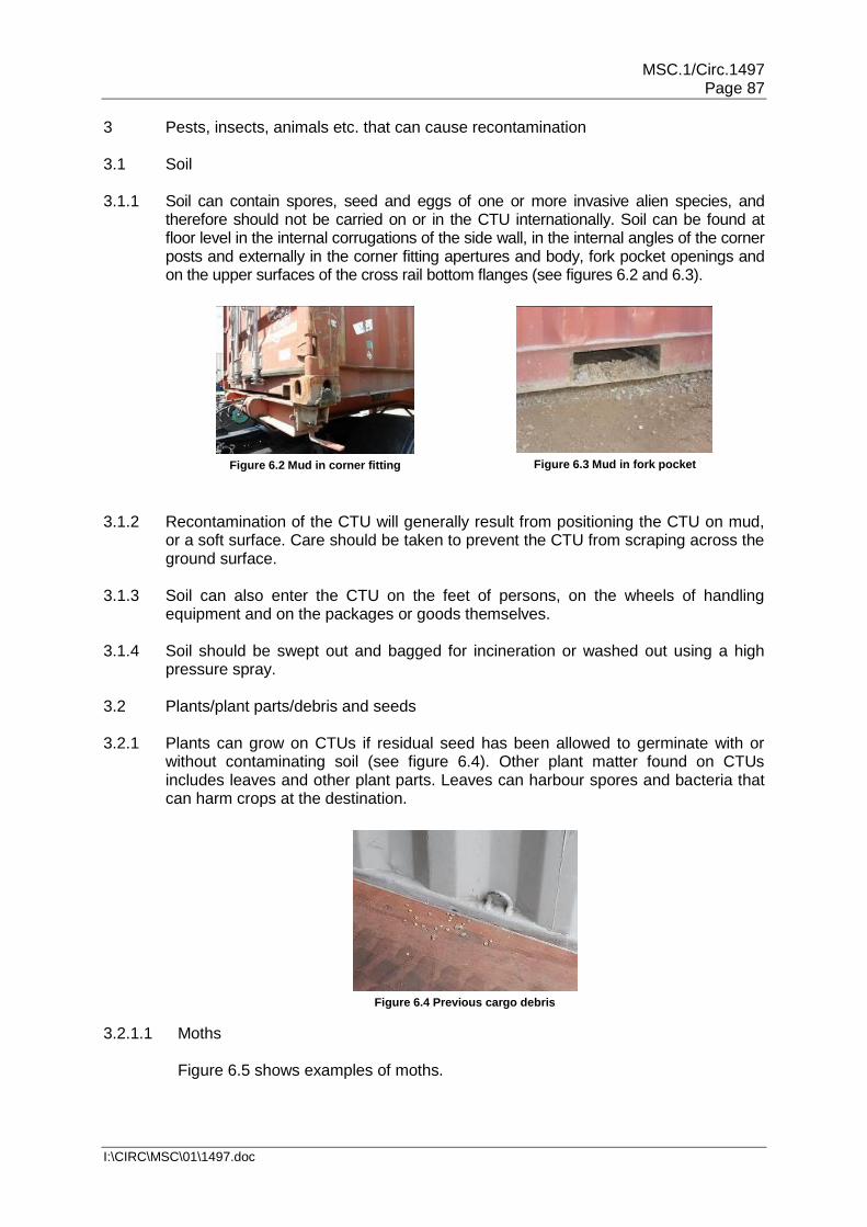
MSC.1/Circ.1497 Page 87
I:\CIRC\MSC\01\1497.doc
3 Pests, insects, animals etc. that can cause recontamination 3.1 Soil 3.1.1 Soil can contain spores, seed and eggs of one or more invasive alien species, and
therefore should not be carried on or in the CTU internationally. Soil can be found at floor level in the internal corrugations of the side wall, in the internal angles of the corner posts and externally in the corner fitting apertures and body, fork pocket openings and on the upper surfaces of the cross rail bottom flanges (see figures 6.2 and 6.3).
Figure 6.2 Mud in corner fitting
Figure 6.3 Mud in fork pocket
3.1.2 Recontamination of the CTU will generally result from positioning the CTU on mud, or a soft surface. Care should be taken to prevent the CTU from scraping across the ground surface.
3.1.3 Soil can also enter the CTU on the feet of persons, on the wheels of handling
equipment and on the packages or goods themselves. 3.1.4 Soil should be swept out and bagged for incineration or washed out using a high
pressure spray. 3.2 Plants/plant parts/debris and seeds 3.2.1 Plants can grow on CTUs if residual seed has been allowed to germinate with or
without contaminating soil (see figure 6.4). Other plant matter found on CTUs includes leaves and other plant parts. Leaves can harbour spores and bacteria that can harm crops at the destination.
Figure 6.4 Previous cargo debris
3.2.1.1 Moths Figure 6.5 shows examples of moths.

MSC.1/Circ.1497 Page 88
I:\CIRC\MSC\01\1497.doc
Figure 6.5 Asian gipsy moth
3.2.1.2 Snails and slugs Figure 6.6 shows examples of snails.
Figure 6.6 Giant African snail
3.3 Ants 3.3.1 Some ant species are considered pests, and because of the adaptive nature of ant
colonies, eliminating the entire colony is nearly impossible. Pest management is therefore a matter of controlling local populations, instead of eliminating an entire colony, and most attempts at control are temporary solutions.
Figure 6.7 Pharaoh ant
Figure 6.8 Carpenter ant nest
3.3.2 Ants classified as pests include the pavement ant, yellow crazy ant, sugar ants, the Pharaoh ant (see figure 6.7), carpenter ants (see figure 6.8), Argentine ant, odorous house ants, red imported fire ant and European fire ant. Populations are controlled using insecticide baits, either in granule or liquid formulations. Bait is gathered by the ants as food and brought back to the nest where the poison is inadvertently spread to other colony members through trophallaxis. Boric acid and borax are often used as insecticides that are relatively safe for humans. Bait may be broadcast over a large area to control species like the red fire ant that occupy large areas.
3.3.3 Individual ants should be swept out of CTUs if possible, but larger colonies or
infestations, require the entire colony to be destroyed and removed for incineration.

MSC.1/Circ.1497 Page 89
I:\CIRC\MSC\01\1497.doc
3.4 Bees and wasps Figures 6.9 and 6.10 show examples of wasp and wasp nest.
Figure 6.9 Sirex wasp
Figure 6.10 Sirex wasp nest
3.5 Mould and fungi
When CTUs are left in damp, dark conditions fungi and other airborne spores can lodge and grow on the residual soil left on surfaces of a CTU.
3.6 Spiders
Figures 6.11 and 6.12 show examples of spider and spider eggs.
Figure 6.11 Wolf spider
Figure 6.12 Spider eggs
3.7 Frass 3.7.1 Frass is the fine powdery material phytophagous (plant-eating) insects pass as
waste after digesting plant parts. It causes plants to excrete chitinase due to high chitin levels, it is a natural bloom stimulant, and has high nutrient levels. Frass is known to have abundant amoeba, beneficial bacteria, and fungi content. Frass is a microbial inoculant, also known as a soil inoculant, which promotes plant health using beneficial microbes. It is a large nutrient contributor to the rainforest, and it can often be seen in leaf mines.
3.7.2 Frass can also refer to the excavated wood shavings that insects like the carpenter
ants kick out of their galleries during the mining process. Carpenter ants do not eat wood, so they discard the shavings as they tunnel (see figure 6.13).

MSC.1/Circ.1497 Page 90
I:\CIRC\MSC\01\1497.doc
Figure 6.13 Wood frass from boring insect
3.7.3 Frass is a general sign of the presence of a wood boring or another insect and therefore in need of cleaning. It is essential that affected plants or timber be removed and incinerated.
3.8 Animals (including frogs) Figure 6.14 shows examples of animals.
Figure 6.14 Squirrels and frogs
4 Contaminant treatment 4.1 The contaminant treatment method should be that most effective for the
contamination present. Consideration should be given to containment and treatment of pests that have a potential for spread. In some cases national authorities may request the specimen be collected for identification purposes.
4.2 If a CTU is found to have a minor recontamination, cleaning can be effected using
one of the following methods:
Sweeping out or vacuum cleaning the CTU and applying an absorbent powder if required;
Using low pressure water wash;
Scraping.
4.3 If a live animal or insect is found which can be swept or washed out then this should be done. Bodies of animals should be disposed of safely by bagging and incineration. If the animal is considered as too dangerous to remove, then close the CTU's doors and inform the CTU supplier.
4.4 Intermodal operators may have contracts with pest control organizations who may
be employed to remove serious recontamination.
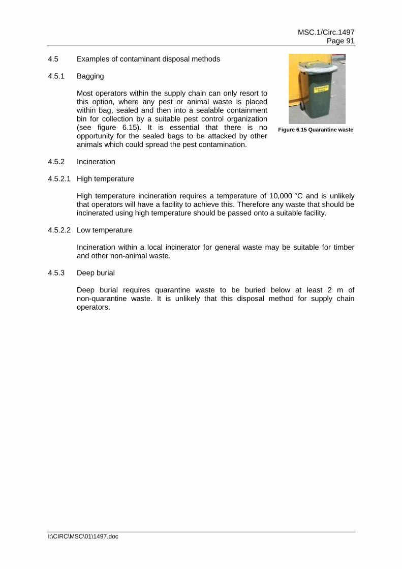
MSC.1/Circ.1497 Page 91
I:\CIRC\MSC\01\1497.doc
4.5 Examples of contaminant disposal methods 4.5.1 Bagging Most operators within the supply chain can only resort to
this option, where any pest or animal waste is placed within bag, sealed and then into a sealable containment bin for collection by a suitable pest control organization (see figure 6.15). It is essential that there is no opportunity for the sealed bags to be attacked by other animals which could spread the pest contamination.
4.5.2 Incineration 4.5.2.1 High temperature High temperature incineration requires a temperature of 10,000 °C and is unlikely
that operators will have a facility to achieve this. Therefore any waste that should be incinerated using high temperature should be passed onto a suitable facility.
4.5.2.2 Low temperature Incineration within a local incinerator for general waste may be suitable for timber
and other non-animal waste. 4.5.3 Deep burial Deep burial requires quarantine waste to be buried below at least 2 m of
non-quarantine waste. It is unlikely that this disposal method for supply chain operators.
Figure 6.15 Quarantine waste

MSC.1/Circ.1497 Page 92
I:\CIRC\MSC\01\1497.doc
Annex 7. Packing and securing cargo into CTUs 1 Planning of packing 1.1 When applicable, planning of packing should be conducted as early as possible and
before packing actually commences. Foremost, the fitness of the envisaged CTU should be verified (see chapter 7 of this Code). Deficiencies should be rectified before packing starts.
1.2 Planning should aim at producing either a tight stow, where all cargo packages are
placed tightly within the boundaries of the side and front walls of the CTU, or a secured stow, where packages do not fill the entire space and will therefore be secured within the boundaries of the CTU by blocking and/or lashing.
1.3 The compatibility of all items of cargo and the nature, i.e. type and strength, of any
packages or packaging involved should be taken into account. The possibility of cross-contamination by odour or dust, as well as physical or chemical compatibility, should be considered. Incompatible cargoes should be segregated.
1.4 In order to avoid cargo damage from moisture in closed CTUs during long voyages,
care should be taken that other wet cargoes, moisture inherent cargoes or cargoes liable to leak are not packed together with cargoes susceptible to damage by moisture. Wet timber planks and bracings, pallets or packagings should not be used. In certain cases, damage to equipment and cargo by condensed water dripping from above may be prevented by the use of protective material such as polythene sheeting. However, such sheeting or wrapping may promote mildew and other water damage, if the overall moisture content within the CTU is too high. If drying agents are to be used, the necessary absorption capacity should be calculated. More information may be found in annex 3.
1.5 Any special instructions on packages, or otherwise available, should be followed,
e.g.:
Cargoes marked "this way up" should be packed accordingly;
Maximum stacking height marked should not be exceeded.
Note: See appendix 1 to this annex for further details on packaging marks.
1.6 Where packing results in stacks of packages, the strength of the individual packages should be capable of supporting those placed above them. Care should be taken that the stacking strength of packages is appropriate for the stack design.
1.7 Consideration should be given to potential problems, which may be created for
those persons who unpack the CTU at its destination. The possibility of cargo falling out when the CTU is opened should definitely be avoided.
1.8 The mass of the planned cargo should not exceed the maximum payload of the
CTU. In the case of freight containers, this ensures that the permitted maximum gross mass of the freight container, marked on the CSC safety approval plate, will not be exceeded. For CTUs not marked with their maximum permissible gross mass or payload, these values should be identified before packing starts.

MSC.1/Circ.1497 Page 93
I:\CIRC\MSC\01\1497.doc
1.9 Notwithstanding the foregoing, any limitation of height or mass along the projected route that may be dictated by regulations or other circumstances, such as lifting, handling equipment, clearances and surface conditions, should be complied with. Such mass limits may be considerably lower than the permitted gross mass referred to above.
1.10 When a heavy package with a small "footprint" will be shipped in a CTU, the
concentrated load should be transferred to the structural transverse and longitudinal bottom girders of the CTU (see section 3.1 of this annex for details).
1.11 In longitudinal direction the centre of gravity of the packed cargo should be within
allowed limits. In transverse direction the centre of gravity should be close to the half width of the CTU. In vertical direction the centre of gravity should be below half the height of the cargo space of the unit. If these conditions cannot be met, suitable measures should be taken to ensure the safe handling and transporting of the CTU, e.g. by external marking of the centre of gravity and/or by instructing forwarders/carriers. In case of CTUs, which will be lifted by cranes or container bridges, the longitudinal centre of gravity should be close to a position at half the length of the CTU (see appendix 4 to this annex).
1.12 If the planned cargo of an open-topped or open-sided CTU will project beyond the
overall dimensions of the unit, suitable arrangements should be made with the carriers or forwarders for accommodating compliance with road or rail traffic regulations or advising on special stowage locations on a ship.
1.13 When deciding on packaging and cargo-securing material, it should be borne in
mind that some countries enforce a garbage and litter avoidance policy. This may limit the use of certain materials and imply fees for the recovery of packaging at the reception point. In such cases, reusable packaging and securing material should be used. Increasingly, countries require timber dunnage, bracings and packaging materials to be free of bark.
1.14 If a CTU is destined for a country with wood treatment quarantine regulations, care
should be taken that all wood in the unit, packaging and cargo complies with the International Standards for Phytosanitary Measures, No. 15 (ISPM 15)20.This standard covers packaging material made of natural wood such as pallets, dunnage, crating, packing blocks, drums, cases, load boards and skids. Approved measures of wood treatment are specified in Annex I of ISPM 15. Wood packaging material subjected to these approved measures should display the following specified mark:
I
P
P
C
XX – 000
YY
I
P
P
C
XX -
000
YY
Figure 7.1 Phytosanitary mark
20 Secretariat of the International Plant Protection Convention, Food and Agriculture Organization of the
United Nations: Regulation of wood packaging material in international trade.

MSC.1/Circ.1497 Page 94
I:\CIRC\MSC\01\1497.doc
The marks indicating that wood packaging and dunnage material has been subjected to approved phytosanitary treatment in accordance with the symbols shown in figure 7.1 will have the following components:
1.14.1 Country code The country code should be the International Organization for Standardization (ISO)
two letter code (shown in the figure as "XX"). 1.14.2 Producer/treatment provider code The producer/treatment provider code is a unique code assigned by the national
plant protection organization to the producer of the wood packaging material, who is responsible for ensuring that appropriate wood is used (shown in the figure as "000").
1.14.3 Treatment code The treatment code (shown as "YY" in the figure) shows the abbreviation for the
approved measure used (HT for heat treatment, MB for fumigation with methyl bromide). In Europe the letters "DB" can be added where debarking has been done.
Note: Treatment should be carried out before the packaging and dunnage material
is packed into the CTU. In situ treatment is not permitted. 1.15 Damaged packages should not be packed into a CTU, unless precautions have
been taken against harm from spillage or leakage (see also chapter 10 of this Code on dangerous goods). The overall capability to resist handling and transport stresses should be ensured.
1.16 The result of planning the packing of a CTU may be presented to the packers by
means of an oral or written instruction or by a sketch or even scale drawing, depending on the complexity of the case. Appropriate supervision and/or inspection should ensure that the planned concept is properly implemented.
2 Packing and securing materials 2.1 Dunnaging and separating material 2.1.1 Dunnaging materials should be used as appropriate for the protection of the cargo
against water from condensed humidity, in particular by:
Timber planks against water collecting at the bottom of the CTU;
Gunny cloth, paperboard or natural fibre mats against water dropping from the ceiling; and
Timber planks or plywood against sweat water running down the sides of the CTU.
2.1.2 Timber planks or scantlings may also be used for creating gaps between parcels of cargo in order to facilitate natural ventilation, particularly in ventilated containers. Moreover, the use of such dunnaging is indispensable, when packing reefer containers.

MSC.1/Circ.1497 Page 95
I:\CIRC\MSC\01\1497.doc
2.1.3 Timber planks, plywood sheets or pallets may be used to equalize loads within stacks of cargo parcels and to stabilize these stacks against dislocation or collapse. The same material may be used for separating packages, which may damage each other or even for installing a temporary floor in a CTU for eliminating inappropriate stack loads to the cargo (see figure 7.2).
Figure 7.2 Timber temporary floor
2.1.4 Cardboard or plastic sheathing may be used for protecting sensitive cargo from dirt,
dust or moisture, in particular while packing is still in progress. 2.1.5 Dunnaging material, in particular sheets of plastic or paper and fibre nets may be
used for separating unpackaged cargo items, which are designated for different consignees.
2.1.6 The restrictions on the use of dunnaging materials with regard to quarantine
regulations, in particular wood or timber, should be kept in mind (see sections 1.13 and 1.14 of this annex).
2.2 Friction and friction increasing material 2.2.1 For handling and packing of cartons and pushing heavy units a low friction surface
may be desirable. However, for minimizing additional securing effort, a high friction between the cargo and the stowage ground of the CTU is of great advantage. Additionally, good friction between parcels or within the goods themselves, e.g. powder or granulate material in bags, will support a stable stow.
2.2.2 The magnitude of the vertical friction forces between a cargo item and the stowage ground depends on the mass of the item, the vertical acceleration coefficient and a specific friction factor µ, which may be obtained from appendix 2 to this annex.
Friction force:
FF = µ · cz · m · g [kN], with mass of cargo [t] and g = 9.81 [m/s2]
2.2.2.1 The factors presented in appendix 2 are applicable for static friction between different surface materials. These figures may be used for cargoes secured by blocking or by friction lashings.
2.2.2.2 For cargoes secured by direct securing, a dynamic friction factor should be used with 75% of the applicable static friction factor, because the necessary elongation of the lashings for attaining the desired restraint forces will go along with a little movement of the cargo.
2.2.2.3 The friction values given in appendix 2 to this annex are valid for swept clean dry or wet surfaces free from frost, ice, snow, oil and grease. When a combination of contact surfaces is missing in the table in appendix 2 or if the friction factor cannot

MSC.1/Circ.1497 Page 96
I:\CIRC\MSC\01\1497.doc
be verified in another way, the maximum friction factor to be used in calculations is 0.3. If the surface contact is not swept clean, the maximum friction factor to be used is 0.3 or the value in the table, when this is lower. If the surface contacts are not free from frost, ice and snow a friction factor µ = 0.2 should be used unless the table shows a lower value. For oily and greasy surfaces or when slip sheets have been used a friction factor µ = 0.1 should be used. The friction factor for a material contact can be verified by static inclination or dragging tests. A number of tests should be performed to establish the friction for a material contact (see appendix 3 to this annex).
2.2.3 Friction increasing materials like rubber mats, sheets of structured plastics or special
cardboard may provide considerably higher friction factors, which are declared and certified by the manufacturers. However, care should be taken in the practical use of these materials. Their certified friction factor may be limited to perfect cleanliness and evenness of the contact areas and to specified ambient conditions of temperature and humidity. The desired friction increasing effect will be obtained only if the weight of the cargo is fully transferred via the friction increasing material, this means only if there is no direct contact between the cargo and the stowage ground. Manufacturer's instructions on the use of the material should be observed.
2.3 Blocking and bracing material and arrangements 2.3.1 Blocking, bracing or shoring is a securing method, where e.g. timber beams and
frames, empty pallets or dunnage bags are filled into gaps between cargo and solid boundaries of the CTU or into gaps between different packages (see figure 7.3). Forces are transferred in this method by compression with minimal deformation. Inclined bracing or shoring arrangements bear the risk of bursting open under load and should therefore be properly designed. In CTUs with strong sides, if possible, packages should be stowed tightly to the boundaries of the CTU on both sides, leaving the remaining gap in the middle. This reduces the forces to the bracing arrangement, because lateral g-forces from only one side will need to be transferred at a time.
Figure 7.3 Centre gap with transverse bracing
2.3.2 Forces being transferred by bracing or shoring need to be dispersed at the points of contact by suitable cross-beams, unless a point of contact represents a strong structural member of the cargo or the CTU. Softwood timber cross-beams should be given sufficient overlaps at the shore contact points. For the assessment of bedding and blocking arrangements, the nominal strength of timber should be taken from the following table:

MSC.1/Circ.1497 Page 97
I:\CIRC\MSC\01\1497.doc
Compressive strength normal to
the grain
Compressive strength parallel to
the grain
Bending strength
Low quality 0.3 kN/cm² 2.0 kN/cm² 2.4 kN/cm²
Medium quality 0.5 kN/cm² 2.0 kN/cm² 3.0 kN/cm²
2.3.3 A bracing or shoring arrangement should be designed and completed in such a way
that it remains intact and in place, also if compression is temporarily lost. This requires suitable uprights or benches supporting the actual shores, a proper joining of the elements by nails or clamps and the stabilizing of the arrangement by diagonal braces as appropriate (see figures 7.4 and 7.5).
Figure 7.4 Shoring arrangement showing cross beam
overlap and diagonal braces
Figure 7.5 Shoring arrangement with uprights
and crossbeam
2.3.4 Transverse battens in a CTU, intended to restrain a block of packages in front of the door or at intermediate positions within the CTU, should be sufficiently dimensioned in their cross section, in order to withstand the expected longitudinal forces from the cargo (see figure 7.6). The ends of such battens may be forced into solid corrugations of the side walls of the CTU. However, preference should be given to brace them against the frame structure, such as bottom or top rails or corner posts. Such battens act as beams, which are fixed at their ends and loaded homogeneously over their entire length of about 2.4 metres. Their bending strength is decisive for the force that can be resisted. The required number of such battens together with their dimensions may be identified by calculations, which is shown in appendix 4 to this annex.
Figure 7.6 General layout of fence battens for door protection in a CTU

MSC.1/Circ.1497 Page 98
I:\CIRC\MSC\01\1497.doc
2.3.5 Blocking by nailed on scantlings should be used for minor securing demands only. Depending on the size of the nails used, the shear strength of such a blocking arrangement may be estimated to take up a blocking force between 1 and 4 kN per nail. Nailed on wedges may be favourable for blocking round shapes like pipes. Care should be taken that wedges are cut in a way that the direction of grain supports the shear strength of the wedge. Any such timber battens or wedges should only be nailed to dunnage or timbers placed under the cargo. Wooden floors of closed CTUs are generally not suitable for nailing. Nailing to the softwood flooring of flatracks or platforms and open CTUs may be acceptable with the consent of the CTU operator (see figure 7.7).
Figure 7.7 Properly cut and nailed wedges
2.3.6 In the case of form locking, void spaces should be filled and may be favourably stuffed by empty pallets inserted vertically and tightened by additional timber battens as necessary. Material which may deform or shrink permanently, like rags of gunny cloth or solid foam of limited strength, should not be used for this purpose. Small gaps between unit loads and similar cargo items, which cannot be avoided and which are necessary for the smooth packing and unpacking of the goods, are acceptable and need not to be filled. The sum of void spaces in any horizontal direction should not exceed 15 cm. However, between dense and rigid cargo items, such as steel, concrete or stone, void spaces should be further minimized, as far as possible.
2.3.7 Gaps between cargo that is stowed on and firmly secured to pallets (by lashings or
by shrink foil), need not to be filled, if the pallets are stowed tightly into a CTU and are not liable to tipping (see figure 7.8). Securing of cargo to pallets by shrink foil wrapping is only sufficient if the strength of the foil is appropriate for above purpose. It should be considered that in case of sea transport repetitive high loadings during bad weather may fatigue the strength of a shrink foil and thereby reduce the securing capacity.
Figure 7.8 Cargo firmly secured to pallets by textile lashings

MSC.1/Circ.1497 Page 99
I:\CIRC\MSC\01\1497.doc
2.3.8 If dunnage bags are used for filling gaps21, the manufacturer's instructions on filling pressure and the maximum gap should be accurately observed. Dunnage bags should not be used as a means of filling the space at the doorway, unless precautions are taken to ensure that they cannot cause the door to open violently when the doors are opened. If the surfaces in the gap are uneven with the risk of damage to the dunnage bags by chafing or piercing, suitable measures should be taken for smoothing the surfaces appropriately (see figures 7.9 and 7.10). The blocking capacity of dunnage bags should be estimated by multiplying the nominal burst pressure with the contact area to one side of the blocking arrangement and with a safety factor of 0.75 for single use dunnage bags and 0.5 for reusable dunnage bags (see appendix 4 to this annex).
Figure 7.9 Gap filled with a central dunnage bag
Figure 7.10 Irregular shaped packages blocked with
dunnage bags
2.3.9 The restrictions on the use of blocking and bracing materials with regard to quarantine regulations, in particular for wood or timber, should be kept in mind (see sections 1.13 and 1.14 of this annex).
2.4 Lashing materials and arrangements 2.4.1 Lashings transfer tensile forces. The strength of a lashing may be declared by its
breaking strength or breaking load (BL). The maximum securing load (MSL) is a specified proportion of the breaking strength and denotes the force that should not be exceeded in securing service. The term lashing capacity (LC), used in national and regional standards, corresponds to the MSL. Values for BL, MSL or LC are indicated in units of force, i.e. kilonewton (kN) or dekanewton (daN).
2.4.2 The relation between MSL and the breaking strength is shown in the table below.
The figures are consistent with annex 13 of the IMO Code of Safe Practice for Cargo Stowage and Securing. Corresponding relations according to standards may differ slightly.
Material MSL
shackles, rings, deck eyes, turnbuckles of mild steel
50% of breaking strength
fibre ropes 33% of breaking strength
web lashings (single use) 75% of breaking strength1
web lashings (reusable) 50% of breaking strength
21 Dunnage bags (inflated by air) should not be used for dangerous goods on US railways.

MSC.1/Circ.1497 Page 100
I:\CIRC\MSC\01\1497.doc
wire ropes (single use) 80% of breaking strength
wire ropes (reusable) 30% of breaking strength
steel band (single use) 70% of breaking strength2
chains 50% of breaking strength
1 Maximum allowed elongation 9% at MSL.
2 It is recommended to use 50%.
2.4.3 The values of MSL quoted in the table above rely on the material passing over smooth or smoothed edges. Sharp edges and corners will substantially reduce these values. Wherever possible or practicable, appropriate edge protectors should be used (see figures 7.11 and 7.12).
Figure 7.11 Poor edge protection
Figure 7.12 Edge protectors
2.4.4 Lashings transfer forces under a certain elastic elongation only. They act like a
spring. If loaded more than the specific MSL, elongation may become permanent and the lashing will fall slack. New wire and fibre ropes or lashings may show some permanent elongation until gaining the desired elasticity after repeated re-tensioning. Lashings should be given a pre-tension, in order to minimize cargo movement. However, the initial pre-tension should never exceed 50% of the MSL.
2.4.5 Fibre ropes of the materials manila, hemp, sisal or manila-sisal-mix and moreover
synthetic fibre ropes may be used for lashing purposes. If their MSL is not supplied by the manufacturer or chandler, rules of thumb may be used for estimating the MSL with d = rope diameter in cm:
Natural fibre ropes: MSL = 2 · d2 [kN] Polypropylene ropes: MSL = 4 · d2 [kN] Polyester ropes: MSL = 5 · d2 [kN] Polyamide ropes: MSL = 7 · d2 [kN]
Composite ropes made of synthetic fibre and integrated soft wire strings provide suitable stiffness for handling, knotting and tightening and less elongation under load. The strength of this rope is only marginally greater than that made of plain synthetic fibre.
2.4.6 There is no strength reduction to fibre ropes due to bends at round corners. Rope
lashings should be attached as double, triple or fourfold strings and tensioned by means of wooden turn sticks. Knots should be of a professional type, e.g. bowline

MSC.1/Circ.1497 Page 101
I:\CIRC\MSC\01\1497.doc
knot and double half hitch22. Fibre ropes are highly sensitive against chafing at sharp corners or obstructions.
2.4.7 Web lashings may be reusable devices with integrated ratchet tensioner or one-way
hardware, available with removable tensioning and lockable devices. The permitted securing load is generally labelled and certified as lashing capacity LC. There is no rule of thumb available for estimating the MSL due to different base materials and fabrication qualities. The fastening of web lashings by means of knots reduces their strength considerably and should therefore not be applied.
2.4.8 The elastic elongation of web lashings, when loaded to their specific MSL should not
exceed 9%. Web lashings should be protected against chafing at sharp corners, against mechanical wear and tear in general and against chemical agents like solvents, acids and others.
2.4.9 Wire rope used for lashing purposes in CTUs for sea transport consists of steel
wires with a nominal BL of around 1.6 kN/mm2 and the favourite construction 6 x 19 + 1FC, i.e. 6 strands of 19 wires and 1 fibre core (see figure 7.13). If a certified figure of MSL is not available, the MSL for one-way use may be estimated by MSL = 40 · d2 [kN]. Other available lashing wire constructions with a greater number of fibre cores and less metallic cross section have a considerably lesser strength related to the outer diameter. The elastic elongation of a lashing wire rope is about 1.6% when loaded to one-way MSL, but an initial permanent elongation should be expected after the first tensioning, if the wire rope is new.
d 6 x 12 + 7 FC 6 x 19 + 1 FC
Figure 7.13 Typical lashing wire rope construction
2.4.10 Narrow rounded bends reduce the strength of wire ropes considerably. The residual
strength of each part of the rope at the bend depends on the ratio of bend diameter to the rope diameter as shown in the table below.
ratio: bend diameter/rope diameter 1 2 3 4 5
residual strength with rope steady in the bend
65% 76% 85% 93% 100%
Bending a wire rope around sharp corners, like passing it through the edged hole of an eye-plate, reduces its strength even more. The residual MSL after a 180° turn through such an eye-plate is only about 25% of the MSL of the plain rope, if steady in the bend.
2.4.11 Wire rope lashings in sea transport are usually assembled by means of wire rope
clips. It is of utmost importance that these clips are of appropriate size and applied in correct number, direction and tightness. Recommended types of such wire rope lashing assemblies are shown in figure 7.14. A typical improper assembly is shown in figure 7.15.
22 Knots will reduce the strength of the rope.

MSC.1/Circ.1497 Page 102
I:\CIRC\MSC\01\1497.doc
double wire in bends, no loss of strength
bend diameter with loss of strength
double wire in both bends, no loss of strength
Figure 7.14 Recommended assemblies for wire rope lashing
single wire in bend, loss of strength
clip assembly without bend, wire will slip at marginal load
Figure 7.15 Improper assembly for wire rope lashing
2.4.12 Tensioning and joining devices associated with wire rope lashings in sea transport are generally not standardized. The MSL of turnbuckles and lashing shackles should be specified and documented by the manufacturer and at least match the MSL of the wire rope part of the lashing. If manufacturer information is not available, the MSL of turnbuckles and shackles made of ordinary mild steel may be estimated by MSL = 10 · d2 [kN] with d = diameter of thread of turnbuckle or shackle bolt in cm.
2.4.13 Wire rope lashings in road transport are specified as reusable material of
distinguished strength in terms of lashing capacity (LC), which should be taken as MSL. Connections elements like shackles, hooks, thimbles, tensioning devices or tension indicators are accordingly standardized by design and strength. The use of wire rope clips for forming soft eyes has not been envisaged. Assembled lashing devices are supplied with a label containing identification and strength data (see figure 7.16). When using such material, the manufacturer's instructions should be observed.
Figure 7.16 Standard wire lashing used in road transport with gripping tackle
2.4.14 Lashing chains used in sea transport are generally long link chains of grade 8 steel.
A 13 mm chain of grade 8 steel has a MSL of 100 kN. The MSL for other dimensions and steel qualities should be obtained from the manufacturer's specification. The elastic elongation of the above long link chains is about 1% when loaded to their MSL. Long link chains are sensitive against guiding them around bends of less than about 10 cm radius. The favourite tensioning device is a lever with a so-called climbing hook for re-tightening the lashing during service (see figure 7.17). Manufacturer's instructions and, when existing, national regulations on the use of the tensioning lever and re-tensioning under load should be strictly observed.

MSC.1/Circ.1497 Page 103
I:\CIRC\MSC\01\1497.doc
Figure 7.17 Long link lashing chain with lever tensioner
2.4.15 Chain lashings used in road and rail transport according to European standards are
mainly short link chains. Long link chains are generally reserved for the transport of logs. Short link chains have an elastic elongation of about 1.5%, when loaded to their MSL. The standard includes various systems of tensioners, specially adapted hooks, damping devices and devices to shorten a chain to the desired loaded length. Chain compound assemblies may be supplied with a label containing identification and strength data (see figure 7.18). Manufacturer's instructions on the use of the equipment should be strictly observed.
turnbuckle
label shortening hook
Figure 7.18 Standard chain lashing with shortening hook
2.4.16 Steel band for securing purposes is generally made of high tension steel with a normal breaking strength of 0.8 to 1.0 kN/mm2. Steel bands are most commonly used for unitizing packages to form greater blocks of cargo (see figure 7.19). In sea transport, such steel bands are also used to "tie down" packages to flatracks, platforms or roll-trailers. The bands are tensioned and locked by special manual or pneumatic tools. Subsequent re-tensioning is not possible. The low flexibility of the band material with about 0.3% elongation, when loaded to its MSL, makes steel band sensitive for loosing pre-tension if cargo shrinks or settles down. Therefore, the suitability of steel band for cargo securing is limited and national restrictions on their use in road or rail transport should always be considered. The use of steel bands for lashing purposes should be avoided on open CTUs as a broken lashing could be of great danger if it hangs outside the CTU.
Figure 7.19 Metal ingots unitized by steel banding (securing not completed)
2.4.17 Twisted soft wire should be used for minor securing demands only. The strength of soft wire lashings in terms of MSL is scarcely determinable and their elastic elongation and restoring force is poor.
Climbing hook

MSC.1/Circ.1497 Page 104
I:\CIRC\MSC\01\1497.doc
2.4.18 Modular lashing systems with ready-made web lashings are available in particular for general purpose freight containers, to secure cargo against movement towards the door. The number of lashings should be calculated depending on the mass of the cargo, the MSL of the lashings, the lashing angle, the friction factor, the mode of transport, and the MSL of the lashing points in the freight container.
Figure 7.20 Modular lashing system
2.4.19 In the example shown in figure 7.20, the lashings are connected to the lashing points of the CTU with special fittings and are pre-tensioned by means of buckles and a tensioning tool. More information may be obtained from the producers or suppliers of such modular systems.
3 Principles of packing 3.1 Load distribution 3.1.1 Freight containers, flatracks and platforms are designed according to ISO standards,
amongst others, in such a way that the permissible payload P, if homogeneously distributed over the entire loading floor, can safely be transferred to the four corner posts under all conditions of carriage. This includes a safety margin for temporary weight increase due to vertical accelerations during a sea passage. When the payload is not homogeneously distributed over the loading floor, the limitations for concentrated loads should be considered. It may be necessary to transfer the weight to the corner posts by supporting the cargo on strong timber or steel beams as appropriate (see figure 7.21).
Figure 7.21 Load transfer beams
3.1.2 The bending strength of the beams should be sufficient for the purpose of load transfer of concentrated loads. The arrangement, the required number and the strength of timber beams or steel beams should be designed in consultation with the CTU operator.

MSC.1/Circ.1497 Page 105
I:\CIRC\MSC\01\1497.doc
3.1.3 Concentrated loads on platforms or flatracks should be similarly expanded by bedding on longitudinal beams or the load should be reduced against the maximum payload. The permissible load should be designed in consultation with the CTU operator.
3.1.4 Where freight containers, including flatracks or platforms, will be lifted and handled
in a level state during transport, the cargo should be so arranged and secured in the freight container that its joint centre of gravity is close to the mid-length and mid-width of the freight container. The eccentricity of the centre of gravity of the cargo
should not exceed 5% in general. As a rule of thumb this can be taken as 60% of the cargo's total mass in 50% of the freight container's length. Under particular
circumstances an eccentricity of up to 10% could be accepted, as advanced spreaders for handling freight containers are capable of adjusting for such eccentricity. The precise longitudinal position of the centre of gravity of the cargo may be determined by calculation (see appendix 4 to this annex).
3.1.5 Roll trailers have structural properties similar to platforms, but are less sensitive to
concentrated loads due to the usual wheel support at about 3/4 of their length from the gooseneck tunnel end. As they are generally handled without lifting, the longitudinal position of the cargo centre of gravity is also not as critical.
3.1.6 Swap bodies have structural properties similar to freight containers, but in most
cases less tare weight and less overall strength. They are normally not stackable. The loading instructions given under subsection 3.1.2 and 3.1.5 should be applied to swap bodies as appropriate.
3.1.7 Road trucks and road trailers are in particular sensitive regarding the position of the
centre of gravity of the cargo packed in them, due to specified axle loads for maintaining steering and braking ability. Such vehicles may be equipped with specific diagrams, which show the permissible cargo mass as a function of the longitudinal position of its centre of gravity. Generally, the maximum cargo mass may be used only when the centre of gravity (CoG) is positioned within narrow boundaries about half the length of the loading space (see figures 7.22 and 7.23).
Figure 7.22 An example of a load distribution diagram for a rigid truck

MSC.1/Circ.1497 Page 106
I:\CIRC\MSC\01\1497.doc
Figure 7.23 An example of a load distribution diagram for a semi-trailer
3.1.8 Railway routes are generally classified into line categories, by which permissible
axle loads and loads per metre length of cargo space are allocated to each railway wagon. The applicable figures should be observed in view of the intended route of the wagon. Tolerable concentrated loads are graded depending on their bedding length. The appropriate load figures are marked on the wagons. The transverse and longitudinal deviation of cargo centre of gravity from wagon centre-lines is limited by defined relations of transverse wheel loads and longitudinal axle/bogie loads. The proper loading of railway wagons should be supervised by specifically trained persons.
3.2 General stowage/packing techniques 3.2.1 Stowage and packing techniques should be suitable to the nature of the cargo with
regard to weight, shape, structural strength and climatic conditions. This includes the proper use of dunnage material (see section 2.1 of this annex), the selection of the appropriate method of mechanical handling and the proper stowage of vented packages. The concept of stowage should incorporate the feasibility of smooth unloading.
3.2.2 Any marking on parcels should be strictly observed. Cargoes marked "this way up"
should not only be stowed upright but also kept upright during entire handling. Goods which may be subject to inspection by the carrier or by authorities, like dangerous goods or goods liable to Customs duty, should, if possible, be stowed at the door end of the CTU.
3.2.3 When packing mixed cargoes, their compatibility should be considered. Irrespective
of the regulations for the stowage of dangerous goods (see chapter 10 of this Code) the following general rules are applicable:
Heavier cargoes should not be stowed on top of lighter cargoes. This will also provide for the centre of gravity of the CTU in a level not exceeding half the height of the CTU;
Heavy units should not be stowed on top of fragile parcels;
Sharp-edged pieces should not be stowed on top of units with weak surfaces;
Liquid cargoes should not be stowed on solid cargoes;
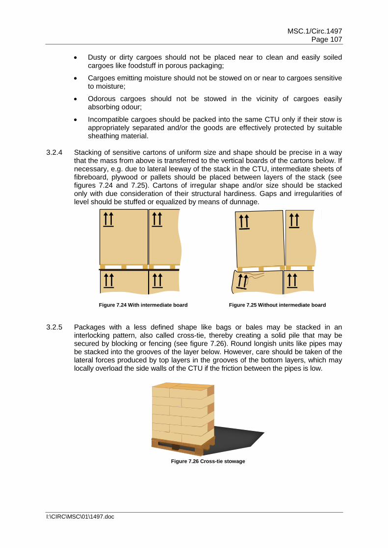
MSC.1/Circ.1497 Page 107
I:\CIRC\MSC\01\1497.doc
Dusty or dirty cargoes should not be placed near to clean and easily soiled cargoes like foodstuff in porous packaging;
Cargoes emitting moisture should not be stowed on or near to cargoes sensitive to moisture;
Odorous cargoes should not be stowed in the vicinity of cargoes easily absorbing odour;
Incompatible cargoes should be packed into the same CTU only if their stow is appropriately separated and/or the goods are effectively protected by suitable sheathing material.
3.2.4 Stacking of sensitive cartons of uniform size and shape should be precise in a way
that the mass from above is transferred to the vertical boards of the cartons below. If necessary, e.g. due to lateral leeway of the stack in the CTU, intermediate sheets of fibreboard, plywood or pallets should be placed between layers of the stack (see figures 7.24 and 7.25). Cartons of irregular shape and/or size should be stacked only with due consideration of their structural hardiness. Gaps and irregularities of level should be stuffed or equalized by means of dunnage.
Figure 7.24 With intermediate board
Figure 7.25 Without intermediate board
3.2.5 Packages with a less defined shape like bags or bales may be stacked in an
interlocking pattern, also called cross-tie, thereby creating a solid pile that may be secured by blocking or fencing (see figure 7.26). Round longish units like pipes may be stacked into the grooves of the layer below. However, care should be taken of the lateral forces produced by top layers in the grooves of the bottom layers, which may locally overload the side walls of the CTU if the friction between the pipes is low.
Figure 7.26 Cross-tie stowage

MSC.1/Circ.1497 Page 108
I:\CIRC\MSC\01\1497.doc
3.2.6 Uniform parcels like drums or standardized pallets should be packed in a way that minimizes lost space and provides a tight stow at the same time. Drums may be stowed either in regular lines, also called "soldier stowage", or into the vertical grooves, also called "offset stowage" (see figures 7.27 and 7.28). With small drums the offset packing is more effective, while with greater drum diameters the advantage may be with the soldier stow. Pallet dimensions are widely standardized and adapted to the inner width and length of cargo spaces in road trucks, road trailers and swap bodies, but not throughout to the inner dimensions of freight containers.
Figure 7.27 Mixed stow, dry over wet goods
Figure 7.28 Mixed stow, use of pallets
3.2.7 Near to completion of packing a CTU, care should be taken to build a firm face of the cargo so as to prevent a "fall out" when the CTU is opened. If there is any doubt about the stability of the face, further steps should be taken such as strapping top layers of cargo back to securing points or building a timber fence between the rear posts in a CTU (see subsection 2.3.4 of this annex). It should be borne in mind, that a freight container on a trailer usually inclines towards the doors aft and that cargo may move against the doors due to vibration induced shift or by jolts during transport.
3.3 Cargo handling 3.3.1 Relevant regulations on the use of personnel protection equipment (helmet, shoes,
gloves and clothing) should be adhered to. Personnel should have been instructed on ergonomic aspects of manual lifting of weighty parcels. Weight limitations of parcels to be lifted and carried by persons should be observed.
3.3.2 Forklift trucks, used for driving inside roofed CTUs, should have a short lifting mast
and a low driver's overhead guard. If the lift truck operates inside a CTU care should be taken of the exhaust gases and equipment with electric power supply or similar should be used. The truck should be equipped with adequate lighting so that the operator can place packages accurately. Forklift trucks s operated by a combustion engine should comply with national combustion emission standards. Forklift trucks s with engines burning LPG fuel should not be used in enclosed space, in order to prevent the accumulation of explosive gas mixtures from unexpected leaks.
3.3.3 Where there is a risk of explosion due to the vapours, fumes or dust given off by the
cargo, all electrical equipment mounted on the forklift trucks should be evaluated to ensure that they are safe for flammable and explosive atmospheres.
3.3.4 Driving forklift trucks into swap bodies, semi-trailers or other supported CTUs should
be done slowly, in particular with careful starting and braking, in order to avoid dangerous horizontal forces to the supports of the CTU.

MSC.1/Circ.1497 Page 109
I:\CIRC\MSC\01\1497.doc
3.3.5 If CTUs are to be packed with forklift trucks from the side, significant lateral impact forces to the CTU should be avoided. Such lateral forces may occur when packages or overpacks are pushed across the loading area. If, during such operations, there is a risk of turning the CTU over packers may consider packing either from both sides to the centre line of the CTU or by using forklift trucks with higher capacity and long forks, which would permit accurate placement without pushing.
3.3.6 If persons need to access the roof of a CTU, e.g. for filling the CTU with a free-
flowing bulk cargo, the load-bearing capability of the roof should be considered. Roofs of freight containers are designed for and tested with a load of 300 kg (660 lbs), which acts uniformly on an area of 600 x 300 mm (24 x 12 inches) in the weakest region of the roof (reference: CSC, Annex II). Practically, no more than two persons should work on a freight container roof simultaneously.
3.3.7 When loading or unloading heavy parcels with C-hooks through doors or from the
sides of a CTU, care should be taken, that the transverse or longitudinal girders of the roof or side walls are struck neither by the hook nor the cargo. The movement of the unit should be controlled by appropriate means, e.g. guide ropes. Relevant regulations for the prevention of accidents should be observed.
4 Securing of cargo in CTUs 4.1 Aims and principles of securing 4.1.1 Arrangements or stacks of cargo items should be packed in a way so as not to
deform and to remain in place and upright with no tilting by their static friction and by their inherent stability, while packing or unpacking a CTU is in progress. This guarantees the safety of packers before additional securing devices are put in place or after such devices have been removed for unpacking.
4.1.2 During transport the CTU may be subjected to vertical, longitudinal and transverse
accelerations, which cause forces to each cargo item, which are proportional to its mass. It should not be assumed, that because a package is heavy, it will not move during transport. The relevant accelerations are outlined in chapter 5 of this Code in units of g, indicating the corresponding forces in units of weight of the distinguished cargo item. These forces may easily exceed the capability of static friction and tilting stability, so that cargo items may slide or tilt over. In addition, the CTU may be simultaneously subjected to temporary vertical accelerations, which cause a weight decrease, thereby reduce the friction and the inherent tilting stability, thus promoting sliding and tipping. Any securing of cargo should aim at the avoidance of such unwanted cargo behaviour. All parts of the cargo should remain in place and neither slide nor tip under the stipulated accelerations of the CTU during the intended route of transport.
4.1.3 Practical securing of cargo may be approached by three distinguished principles,
which may be used individually or combined as appropriate:
Direct securing is effected by the immediate transfer of forces from the cargo to the CTU by means of blocking, lashings, shores or locking devices. The securing capacity is proportional to the MSL of the securing devices;
Friction securing is achieved by so-called tie-down or top-over lashings which, by their pre-tension, increase the apparent weight of the cargo and thereby the friction to the loading ground and also the tilting stability. The securing effect is proportional to the pre-tension of the lashings. Anti-slip material in the sliding surfaces considerably increases the effect of such lashings;

MSC.1/Circ.1497 Page 110
I:\CIRC\MSC\01\1497.doc
Compacting cargo by bundling, strapping or wrapping is an auxiliary measure of securing that should always be combined with measures of direct securing or friction securing.
4.1.4 Lashings used for direct securing will inevitably elongate under external forces, thus
permitting the package a degree of movement. To minimize this movement, (horizontal or lateral sliding, tipping or racking) it should be ensured that the:
Lashing material has appropriate load-deformation characteristics (see section 2.4 of this annex);
Length of the lashing is kept as short as practicable; and
Direction of the lashing is as close as possible to the direction of the intended restraining effect.
A good pre-tension in lashings will also contribute to minimizing cargo motions, but
the pre-tension should never exceed 50% of the MSL of the lashing. Direct securing by stiff pressure elements (shores or stanchions) or by locking devices (locking cones or twist-locks) will not allow significant cargo motion and should therefore be the preferred method of direct securing.
4.1.5 Lashings used for friction securing should be able to maintain the vital pre-tension
for a longer period and should not fall slack from minor settling or shrinking of the cargo. Therefore synthetic fibre web lashings should be preferred to e.g. chains or steel band lashings. The pre-tension of tie-down lashings does in principle not fall under the limitation stated above for direct lashings, but will generally not be greater than 20% of the MSL of the lashing with manually operated tensioners. Care should be taken to establish this pre-tension on both sides of the lashing as far as is practical. For assessing a friction securing arrangement by calculation, the labelled standard pre-tension23 should be used. If such marking is not available, a rule of thumb value of 10% of the breaking strength of the lashing, but not more than 10 kN, should be used for calculation.
4.1.6 Arrangements of direct securing devices should be homogeneous in a way that
each device in the arrangement takes its share of the restraining forces appropriate to its strength. Unavoidable differences in load distribution within complex arrangements may be compensated for by the application of a safety factor. Nevertheless, devices of diverging load-deformation properties should not be placed in parallel, unless used for the distinguishable purposes of sliding prevention and tipping prevention. If, for instance, timber blocking and direct web lashing is used in parallel against sliding, the stiffer timber blocking should be dimensioned so as to resist the expected load alone. This restriction does not apply to the combination of tie-down lashings and e.g. timber blocking.
4.1.7 Any cargo securing measures should be applied in a manner that does not affect,
deform or impair the package or the CTU. Permanent securing equipment incorporated into a CTU should be used whenever possible or necessary.
4.1.8 During transport, in particular at suitable occasions of a multimodal transport route,
securing arrangements in CTUs should be checked and upgraded if necessary and as far as practicable. This includes re-tightening of lashings and wire rope clips and adjusting of blocking arrangements.
23 Standard tension force STF according to EN 12195-2.

MSC.1/Circ.1497 Page 111
I:\CIRC\MSC\01\1497.doc
4.2 Tightly arranged cargoes 4.2.1 A vital prerequisite of cargo items for a tight stowage arrangement is their
insensibility against mutual physical contact. Cargo parcels in form of cartons, boxes, cases, crates, barrels, drums, bundles, bales, bags, bottles, reels etc. or pallets containing the aforesaid items are usually packed into a CTU in a tight arrangement in order to utilize the cargo space, to prevent cargo items from tumbling around and to enable measures of common securing against transverse and longitudinal movement during transport.
4.2.2 A tight stow of uniform or variable cargo items should be planned and arranged
according to principles of good packing practice, in particular observing the advice given in section 3.2 of this annex. If coherence between items or tilting stability of items is poor, additional measures of compacting may be necessary like hooping or strapping batches of cargo items with steel or plastic tape or plastic sheeting. Gaps between cargo items or between cargo and CTU boundaries should be filled as necessary (see subsections 2.3.6 to 2.3.8 of this annex). Direct contact of cargo items with CTU boundaries may require an interlayer of protecting material (see section 2.1 of this annex).
Figure 7.29 Packing 1,000 x 1,200 mm unit loads into a
20-foot container
Figure 7.30 Packing 800 x 1,200 mm unit loads into a
20-foot container
Figure 7.31 Packing 1,000 x 1,200 mm unit loads into a 40-foot container
Note: The void areas (grey shaded) shown in figures 7.29 to 7.31 should be filled when necessary (see subsection 2.3.6 of this annex)
4.2.3 CTUs with strong cargo space boundaries may inherently satisfy transverse and
longitudinal securing requirements in many cases, depending on the type of CTU, the intended route of transport and appropriate friction among cargo items and between cargo and stowage ground. The following balance demonstrates the confinement of tightly stowed cargo within strong cargo space boundaries:
gmcμgPrgmc zyx,yx, [kN]
cx,y = horizontal acceleration coefficient in the relevant mode of transport (see chapter 5 of this Code)
m = mass of cargo packed [t]
g = gravity acceleration 9.81 m/s2
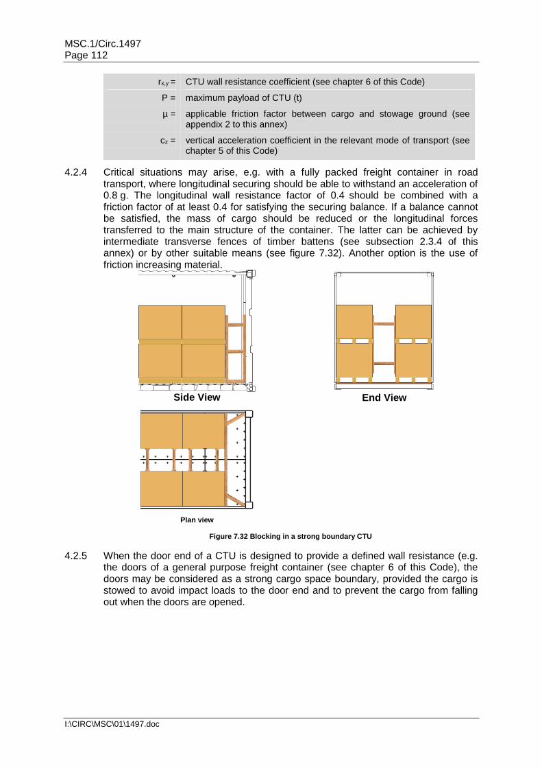
MSC.1/Circ.1497 Page 112
I:\CIRC\MSC\01\1497.doc
rx,y = CTU wall resistance coefficient (see chapter 6 of this Code)
P = maximum payload of CTU (t)
µ = applicable friction factor between cargo and stowage ground (see appendix 2 to this annex)
cz = vertical acceleration coefficient in the relevant mode of transport (see chapter 5 of this Code)
4.2.4 Critical situations may arise, e.g. with a fully packed freight container in road transport, where longitudinal securing should be able to withstand an acceleration of 0.8 g. The longitudinal wall resistance factor of 0.4 should be combined with a friction factor of at least 0.4 for satisfying the securing balance. If a balance cannot be satisfied, the mass of cargo should be reduced or the longitudinal forces transferred to the main structure of the container. The latter can be achieved by intermediate transverse fences of timber battens (see subsection 2.3.4 of this annex) or by other suitable means (see figure 7.32). Another option is the use of friction increasing material.
Side View
End View
Plan view
Figure 7.32 Blocking in a strong boundary CTU
4.2.5 When the door end of a CTU is designed to provide a defined wall resistance (e.g. the doors of a general purpose freight container (see chapter 6 of this Code), the doors may be considered as a strong cargo space boundary, provided the cargo is stowed to avoid impact loads to the door end and to prevent the cargo from falling out when the doors are opened.

MSC.1/Circ.1497 Page 113
I:\CIRC\MSC\01\1497.doc
4.2.6 Where there is the need to stack packages in an incomplete second layer at the centre of the CTU, additional longitudinal blocking can be adopted (see figures 7.33 to 7.36).
Figure 7.33 Threshold by height
Figure 7.34 Threshold by elevation
Figure 7.35 Threshold by board
Figure 7.36 Round turn lashing
4.2.7 CTUs with weak cargo space boundaries like certain road vehicles and swap bodies will regularly require additional securing measures against sliding and tipping of a block of tightly stowed cargo. These measures should also contribute to compacting the block of cargo. The favourite method in this situation is friction-securing by so-called top-over lashings. For obtaining a reasonable securing effect from friction lashings, the friction factor between cargo and stowage ground should be sufficient and the inherent elasticity of the lashings should be able to maintain the pre-tension throughout the course of transport. The following balance demonstrates the confinement of tightly stowed cargo within weak cargo space boundaries and an additional securing force against sliding:
[kN] (Fsec = additional securing force)
If a wall resistance coefficient is not specified for the distinguished CTU, it should be set to zero. The additional securing (Fsec) may consist of blocking the base of the cargo against stronger footing of the otherwise weak cargo space boundary or bracing the block of cargo against stanchions of the cargo space boundary system. Such stanchions may be interconnected by pendants above the cargo for increasing their resistance potential. Alternatively, the additional securing force may be obtained by direct securing methods or top-over lashings. Fsec per top-over lashing is: FV ∙ µ, where FV is the total vertical force from the pre-tension. For vertical lashings FV is 1.8 times the pre-tension in the lashing. For direct lashing arrangements µ should be set to 75% of the friction factor.
seczyx,yx, FgmcμgPrgmc

MSC.1/Circ.1497 Page 114
I:\CIRC\MSC\01\1497.doc
4.2.8 On CTUs without boundaries the entire securing effect should be accomplished by securing measures like top-over lashings, friction increasing material and, if the CTU is a flatrack, by longitudinal blocking against the end-walls. The following balance demonstrates the securing of tightly stowed cargo on a CTU without cargo space boundaries:
[kN] (Fsec = additional securing force)
For Fsec, see subsection 4.2.7. It should be noted that even in case of a friction factor that outnumbers the external acceleration coefficients, without cargo space boundaries a minimum number of top-over lashings is imperative for avoiding migration of the cargo due to shocks or vibration of the CTU during transport.
4.3 Individually secured packages and large unpackaged articles 4.3.1 Packages and articles of greater size, mass or shape or units with sensitive exterior
facing, which does not allow direct contact to other units or CTU boundaries, should be individually secured. The securing arrangement should be designed to prevent sliding and, where necessary, tipping, both in the longitudinal and transverse direction. Securing against tipping is necessary, if the following condition is true (see also figure 7.37):
cx,y = horizontal acceleration coefficient in the relevant modes of transport (see chapter 5 of this Code)
d = vertical distance from centre of gravity of the unit to its tipping axis [m]
cz = vertical acceleration coefficient in the relevant modes of transport (see chapter 5 of this Code)
b = horizontal distance from centre of gravity to tipping axis [m]
b
d
m ∙ cxy
m ∙ cz
Tipping axis
Figure 7.37 Tipping criterion
4.3.2 Individually secured packages and articles should preferably be secured by a direct securing method, i.e. by direct transfer of securing forces from the package to the CTU by means of lashings, shores or blocking.
4.3.2.1 A direct lashing will be between fixed fastening points on the package/article and the
CTU and the effective strength of such a lashing is limited by the weakest element within the device, which includes fastening points on the package as well as fastening points on the CTU.
bcdc zyx,
seczx,y Fgmcμgmc

MSC.1/Circ.1497 Page 115
I:\CIRC\MSC\01\1497.doc
4.3.2.2 For sliding prevention by lashings the vertical lashing angle should preferably be in the range of 30° to 60° (see figure 7.38). For tipping prevention the lashings should be positioned in a way that provides effective levers related to the applicable tipping axis (see figure 7.39).
Figure 7.38 Direct lashing against sliding
+
Lever
Tipping
axis
Figure 7.39 Direct lashing against tipping
4.3.3 Packages and articles without securing points should be either secured by shoring or blocking against solid structures of the CTU or by top-over, half-loop or spring lashings (see figures 7.40 to 7.43).
Figure 7.40 Top over lashing
Figure 7.41 Vertical half-loop lashing
Figure 7.42 Horizontal half-loop lashing
Figure 7.43 Spring lashing
Figure 7.44 Silly-loop lashing

MSC.1/Circ.1497 Page 116
I:\CIRC\MSC\01\1497.doc
4.3.3.1 Loop lashings with their ends fastened to either side (see figure 7.44), also called "silly-loops", do not provide any direct securing effect and may permit the package/article to roll and therefore are not recommended
4.3.3.2 Lashing corner fittings are available to provide alternative lashing to the spring
lashing (see figure 7.43).
4.3.3.3 Any lashing method adopted will require that the lashing material stretches in order to develop a restraining force. As the material relaxes, the tension in the lashing will slowly reduce, therefore it is important that the guidance given in subsection 4.1.4 of this annex should be followed.
4.3.4 CTUs with strong cargo space boundaries favour the method of blocking or shoring
for securing a particular package or article. This method will minimize cargo mobility. Care should be taken that the restraining forces are transferred to the CTU boundaries in a way that excludes local overloading. Forces acting to CTU walls should be transferred by means of load spreading cross beams (see subsections 2.3.1 to 2.3.3 of this annex). Very heavy packages or articles, e.g. steel coils or blocks of marble, may require a combination of blocking and lashing, however with observation of the restrictions lined out in subsection 4.1.6 of this annex (see figure 7.45). Articles with sensitive surfaces may rule out the blocking method and should be secured by lashings only.
Figure 7.45 Transverse blocking of steel slab
4.3.5 Individual securing of packages or articles in CTUs with weak cargo space boundaries and in CTUs without boundaries requires predominantly the method of lashing. Where applicable, blocking or shoring may be additionally applied, but if used in parallel with lashings, the restrictions set out in subsection 4.1.6 of this annex should be observed. Although the provision of good friction in the bedding of a package or article is recommended in any case, the use of top-over lashings for sliding prevention is discouraged unless the cargo has limited mass. Top-over lashings may be suitable for tipping prevention. In particular over-width packages or articles, often shipped on flat bed CTUs, should not be secured solely by top-over lashings (see figure 7.46). The use of half loops and/or spring lashings is strongly recommended (see figures 7.47 and 7.48).

MSC.1/Circ.1497 Page 117
I:\CIRC\MSC\01\1497.doc
STOP
Figure 7.46 Top-over lashing
Figure 7.47 Top-over and
horizontal half-loop
Figure 7.48 Transverse spring
lashing
4.3.6 Where horizontal half loops are used, a means should be provided to prevent the loops from sliding down the package/article.
4.3.7 Alternatively an over-width package or article can be secured by half-loops over the
corners as shown in figure 7.49.
Figure 7.49 Over-width package secured by half-loops
4.4 Evaluation of securing arrangements 4.4.1 Evaluation of securing arrangements means making up a balance of expected
external forces and moments against the securing potential of the planned or implemented securing arrangement. Expected external forces should be determined by multiplying the applicable acceleration coefficient, given in chapter 5 of this Code, with the weight of the package or block of packages in question.
[kN]
Fx,y = expected external force [kN]
m = mass of cargo to be evaluated [t]
g = gravity acceleration 9.81m/s2
cx,y = horizontal acceleration coefficient in the relevant mode of transport (see chapter 5 of this Code)
Chapter 5 distinguishes three modes of transport, road, rail and sea. The sea transport mode is further subdivided into three categories of severity of ship motions, aligned to the significant wave height of distinguished sea areas. Therefore the selection of the applicable acceleration factor requires the full information on the
yx,yx, cgmF

MSC.1/Circ.1497 Page 118
I:\CIRC\MSC\01\1497.doc
intended mode and route of transport. Due consideration should be given to possible multimodal transport, in order to identify the acceleration figures for the most demanding mode or leg of the transport route. These figures should be finally used for the evaluation of the securing arrangement.
4.4.2 The assessment of the securing potential includes the assumption of a friction factor, based on the combination of materials (see appendix 2 to this annex) and the character of the securing arrangement (subsection 2.2.2 of this annex), and, if applicable, the determination of the inherent tilting stability of the cargo (subsection 4.3.1 of this annex). Any other securing devices used for blocking, shoring or lashing should be estimated by their strength in terms of MSL and relevant application parameters like securing angle and pre-tension. These figures are required for evaluating the securing arrangement.
4.4.3 In many cases the evaluation of a securing arrangement may be accomplished by
means of a simple rule of thumb. However, such rules of thumb may be applicable for certain distinguished conditions of transport only, e.g. for sea transport, and may overshoot or fall short in other conditions. It is therefore advisable to phrase such rules of thumb for distinguished modes of transport and use them accordingly. Any phrasing of a rule of thumb should undergo a first-time check by means of an advanced assessment method.
4.4.4 Standardized assessment methods for the evaluation of securing arrangements may
consist of appropriate pre-calculated tables, based on balance calculations, which give quick answers regarding the adequacy of a securing arrangement24. Such methods may be directed to specific modes of transport.
4.4.5 Evaluation of securing arrangements may be carried out by balancing forces and
moments by an elementary calculation. However, the particular method used should be approved and suitable for the intended purpose and mode of transport. Specific guidance may be found in the IMO Code of Safe Practice for Cargo Stowage and Securing (CSS Code) and in various other standards and guidelines issued by regional or national authorities and industry groups covering various modes of transport. References:
IMO CSS Code, Annex 13, for sea transport;
European standard EN 12195-1:2010, for road transport;
International Union of Railways (UIC), Agreement governing the exchange and use of wagons between Railway Undertakings (RIV 2000) Annex II, for rail transport.
4.4.6 The suitability of a specific securing arrangement may be evaluated and approved by
an inclination test. The test may be used to demonstrate resistance against any specified external acceleration. The corresponding test-angle depends on the existing friction factor for a sliding resistance test, or on the relation between the height and the width of cargo for a tipping resistance test (see appendix 5 to this annex).
24 One of the assessment methods is the Quick Lashing Guide that can be found in informative material IM 5
(available at www.unece.org/trans/wp24/guidelinespackingctus/intro.html).

MSC.1/Circ.1497 Page 119
I:\CIRC\MSC\01\1497.doc
5 Packing bulk material 5.1 Non-regulated liquids in tank CTUs 5.1.1 Tank CTUs filled with liquids having a viscosity less than 2,680 mm2/s at 20°C and to be
transported by road, rail or sea should be filled to at least 80% of their volume for avoiding dangerous surging, but never more than 95% of their volume, unless specified otherwise. A filling ratio of maximum 20% is also accepted. A filling ratio of more than 20% and less than 80% should only be permitted when the tank shell is subdivided, by partitions or surge plates, into sections of not more than 7,500 l capacity.
5.1.2 The tank shell and all fittings, valves and gaskets should be compatible with the goods
to be carried in that tank. In case of doubt, the owner or operator of the tank should be contacted. All valves should be correctly closed and checked for leak tightness.
5.1.3 For the transport of foodstuffs, the tank should comply with the following
requirements:
All parts of the tank which are in direct contact with the food stuff should be so conditioned that the overall food-grade property of the tank is guaranteed;
The tank should be easily accessible and suitable for cleaning and disinfection;
Inspection of the interior should be possible;
The exterior should be conspicuously marked with a marking "FOR FOODSTUFFS ONLY" or with a similar wording.
5.2 Liquids in flexitanks
5.2.1 Flexitanks used for the transport of bulk liquids by road, rail or sea should carry a label that confirms the type approval by a recognized consultative body. The flexitank manufacturer's fitting instructions should always be followed, and the cargo intended to be carried should be checked for compatibility with the material of the flexitank. The transport of dangerous goods in flexitanks is prohibited.
5.2.2 During transport the contents of a flexitank will be subject to dynamic forces without significant retention from friction. These forces will act upon the boundaries of the CTU and may cause damage or complete failure.
5.2.3 Therefore the payload of a CTU should be appropriately reduced, when it is used for carrying a loaded flexitank. The reduction depends on the type of CTU and on the mode of transport. When a flexitank is loaded into a general purpose CTU, the mass of the liquid in the flexitank should not exceed a value agreed with the CTU operator, to prevent the CTU from suffering bulging damages (see figure 7.50).
Figure 7.50 Damaged CTU side wall

MSC.1/Circ.1497 Page 120
I:\CIRC\MSC\01\1497.doc
5.2.4 Road vehicles intended to carry loaded flexitanks should have boundaries of a certified strength that is sufficient to confine the weight of the cargo under the accepted load assumptions. The certification of fitness of the vehicle should explicitly address the bulk transport of liquid under the assumption of zero-friction. Nevertheless, the lining of the bottom of the loading area with friction increasing material and the application of over-the-top fibre lashings every two metres is recommended for stabilizing the position and the strength of the flexitank.
5.2.5 Before being fitted with a flexitank, the CTU should be carefully inspected for
structural integrity and fully functional locking bars for each door panel. The CTU should then be prepared by thorough cleaning, removing of all obstacles like protruding nails and by lining the bottom and walls with cardboard. In 40-foot containers plywood should be used for lining of the side walls in order to avoid bulging damage. The door end of the CTU should be reinforced by battens, fitted into suitable recesses, and by a strong lining of cardboard or plywood. If the flexitank is equipped with a bottom connection tube, this lining should have an aperture matching with the position of the tube in way of the right hand door. The empty flexitank should be unfolded and laid out accurately to facilitate a smooth filling process.
5.2.6 For filling an empty flexitank the left hand door of the CTU should be firmly closed so that the inserted barrier is appropriately supported (see figure 7.51). The flexitank should be filled at a controlled rate. The use of spill protection devices like collecting bag or drip tray is recommended. After filling and sealing the tank the door of the CTU should be closed and a warning label should be attached on the left hand door panel (see figure 7.52). No part of the flexitank or retaining battens or bulkhead should touch either door when fully loaded.
Figure 7.51 Container fitted with flexitank
Figure 7.52 Flexitank warning label
5.2.7 For unloading a flexitank, the right hand door of the CTU should be opened carefully for getting access to the top or bottom connection tube of the flexitank. The left hand door should be kept closed until the flexitank is substantially empty. The use of spill protection devices like collecting bag or drip tray is recommended. The empty flexitank should be disposed according to applicable regulations.
5.3 Non-regulated solid bulk cargoes
5.3.1 Non-regulated solid bulk cargoes may be packed into CTUs provided the boundaries of the cargo spaces are able to withstand the static and dynamic forces of the bulk material under the foreseeable transport conditions (see chapter 5 of this Code). Freight containers are equipped with shoring slots in the door corner posts which are suitable to accommodate transverse steel bars of 60 mm square cross section. This arrangement is particularly designed to strengthen the freight container door end for taking a load of 0.6 P, as required for solid bulk cargoes. These bars should be

MSC.1/Circ.1497 Page 121
I:\CIRC\MSC\01\1497.doc
properly inserted. The relevant transport capability of the CTU should be demonstrated by a case-related certificate issued by a recognized consultative body or by an independent cargo surveyor. This requirement applies in particular to general purpose freight containers and to similar closed CTUs on road vehicles, which are not explicitly designed to carry bulk cargoes. It may be necessary to reinforce side and front walls of the CTU by plywood or chipboard facing in order to protect them from bulging or scratching (see figure 7.53).
Figure 7.53 Lining a 40-foot container with chipboard panels
5.3.2 The CTU intended to carry a bulk cargo should be cleaned and prepared adequately as described in subsection 5.2.5 of this annex, in particular if a cargo-specific liner will be used for accommodating bulk cargoes like grain, coffee beans or similar sensible materials (see figure 7.54).
Figure 7.54 CTU with liner bag for accommodating a sensitive bulk cargo
5.3.3 If crude or dirty material will be transported, the CTU boundaries should be lined with plywood or chipboard for avoiding mechanical wastage of the CTU. In all cases an appropriate door protection should be installed consisting of battens fitted into suitable recesses and complemented by a strong plywood liner (see figure 7.55).
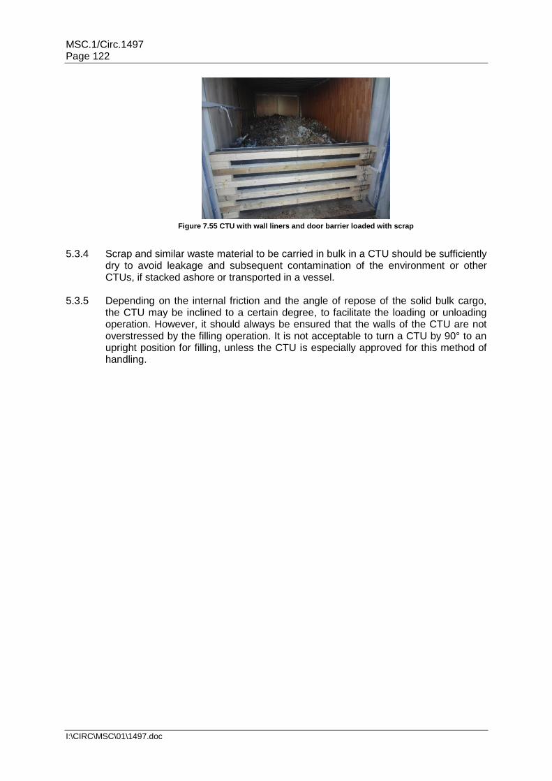
MSC.1/Circ.1497 Page 122
I:\CIRC\MSC\01\1497.doc
Figure 7.55 CTU with wall liners and door barrier loaded with scrap
5.3.4 Scrap and similar waste material to be carried in bulk in a CTU should be sufficiently
dry to avoid leakage and subsequent contamination of the environment or other CTUs, if stacked ashore or transported in a vessel.
5.3.5 Depending on the internal friction and the angle of repose of the solid bulk cargo,
the CTU may be inclined to a certain degree, to facilitate the loading or unloading operation. However, it should always be ensured that the walls of the CTU are not overstressed by the filling operation. It is not acceptable to turn a CTU by 90° to an upright position for filling, unless the CTU is especially approved for this method of handling.

MSC.1/Circ.1497 Page 123
I:\CIRC\MSC\01\1497.doc
Appendix 1. Packaging marks Note: The labels and marks required for the transport of dangerous goods can be
found in the applicable dangerous goods transport regulations and are not included in this Code.
1 Introduction 1.1 Packages are often marked with handling instructions in the language of the country
of origin. While this may safeguard the consignment to some extent, it is of little value for goods consigned to, or through, countries using different languages, and of no value at all if people handling the packages are illiterate.
1.2 Pictorial symbols offer the best possibility of conveying the consignor's intention and
their adoption will, therefore, undoubtedly reduce loss and damage through incorrect handling.
1.3 The use of pictorial symbols does not provide any guarantee of satisfactory
handling; proper protective packaging is therefore of primary importance. 1.4 The symbols shown in this annex are those most regularly exhibited. These and
others are shown in ISO standard 78025. 2 Symbols 2.1 Display of symbols 2.1.1 Symbols should preferably be stencilled directly on the package or may appear on a
label. It is recommended that the symbols be painted, printed or otherwise reproduced as specified in this ISO standard. They need not be framed by border lines.
2.1.2 The graphical design of each symbol should have only one meaning; symbols are
purposely designed so that they can also be stencilled without changing the graphics.
2.2 Colour of symbols 2.2.1 The colour used for symbols should be black. If the colour of the package is such
that the black symbol would not show clearly, a panel of a suitable contrasting colour, preferably white, should be provided as a background.
2.2.2 Care should be taken to avoid the use of colours which could result in confusion with
the labelling of dangerous goods. The use of red, orange or yellow should be avoided unless regional or national regulations require such use.
2.3 Size of symbols For normal purposes the overall height of the symbols should be 100 mm, 150 mm
or 200 mm. The size or shape of the package may, however, necessitate use of larger or smaller sizes for the symbols.
25 ISO standard 780, Packaging – Pictorial markings for handling of goods.

MSC.1/Circ.1497 Page 124
I:\CIRC\MSC\01\1497.doc
2.4 Positioning of symbols Particular attention should be paid to the correct application of the symbols, as faulty
application may lead to misinterpretation. Symbols No. 7 and No. 16 should be applied in their correct respective positions and in appropriate respective places in order to convey the meaning clearly and fully.
3 Handling instructions Handling instructions should be indicated on transport packages by using the
corresponding symbols given in the following table.

MSC.1/Circ.1497 Page 125
I:\CIRC\MSC\01\1497.doc
No. Instruction/Information Symbol Meaning Special
Instructions
1 FRAGILE
Contents of the package are fragile therefore should be handled with care.
Shown near the left hand upper corner on all four upright sides of the package.
TOP BOTTOM
2 USE NO HAND HOOKS
Hooks should not be used for handling packages
3 THIS WAY UP
Indicates correct orientation of the package
Shown as symbol No. 1. Where both symbols are required, symbol No. 3 will appear nearer to the corner
TOP BOTTOM
4 KEEP AWAY FROM SUNLIGHT
Package should not be exposed to sunlight.
5 PROTECT FROM RADIOACTIVE SOURCES
Contents of the package may deteriorate or may be rendered totally unusable by penetrating radiation
6 KEEP AWAY FROM RAIN
Package should be kept away from rain and dry

MSC.1/Circ.1497 Page 126
I:\CIRC\MSC\01\1497.doc
No. Instruction/Information Symbol Meaning Special
Instructions
7 CENTRE OF GRAVITY
Indicates the centre of gravity of the package
Where possible,
"Centre of
gravity" should
be placed on all six sides but at least on the four lateral sides relating to the actual location of the centre of gravity
TOP BOTTOM
8 DO NOT ROLL
Package should not be rolled
9 DO NOT USE HAND TRUCK HERE
Hand trucks should not be placed on this side when handling
10 USE NO FORKS
Package should not be handled by forklift trucks
11 CLAMP AS INDICATED
Clamps should be placed on the sides indicated for handling
The symbol should be positioned on two opposite faces of the package so that it is in the visual range of the clamp truck operator when approaching to carry out operation. The symbol should not be marked on those faces of the package intended to be gripped by the clamps.

MSC.1/Circ.1497 Page 127
I:\CIRC\MSC\01\1497.doc
No. Instruction/Information Symbol Meaning Special
Instructions
12 DO NOT CLAMP AS INDICATED
Package should not be handled by clamps on the sides indicated
13 STACKING LIMITED BY MASS
… kg max
Indicates the maximum stacking load permitted.
14 STACKING LIMITED BY NUMBER
n
Maximum number of identical packages that may be stacked
above, where "n" is the limiting number.
15 DO NOT STACK
Stacking the package is not permitted and nothing should be placed on top.
16 SLING HERE
Slings for lifting should be placed where indicated
Should be placed on at least two opposite faces of the package
TOP BOTTOM
17 TEMPERATURE LIMITS
Indicates the temperature limit within which the package should be stored and handled.
… C max
… C min
… C max
… C min

MSC.1/Circ.1497 Page 128
I:\CIRC\MSC\01\1497.doc
Appendix 2. Friction factors
Different material contacts have different friction factors. The table below shows recommended values for the friction factors. The values are valid provided that both contact surfaces are "swept clean" and free from any impurities. The values are valid for the static friction. In case of direct lashings, where the cargo has to move little before the elongation of the lashings provides the desired restraint force, the dynamic friction applies, which is to be taken as 75% of the static friction.
Material combination in contact surface Dry Wet
SAWN TIMBER/WOODEN PALLET
Sawn timber/wooden pallet against fabric base laminate/plywood 0.45 0.45
Sawn timber/wooden pallet against grooved aluminium 0.4 0.4
Sawn timber/wooden pallet against stainless steel sheet 0.3 0.3
Sawn timber/wooden pallet against shrink film 0.3 0.3
PLANED WOOD
Planed wood against fabric base laminate/plywood 0.3 0.3
Planed wood against grooved aluminium 0.25 0.25
Planed wood against stainless steel sheet 0.2 0.2
PLASTIC PALLETS
Plastic pallet against fabric base laminates/plywood 0.2 0.2
Plastic pallet against grooved aluminium 0.15 0.15
Plastic pallet against stainless steel sheet 0.15 0.15
CARDBOARD (UNTREATED)
Cardboard against cardboard 0.5 -
Cardboard against wooden pallet 0.5 -
BIG BAG
Big bag against wooden pallet 0.4 -
STEEL AND SHEET METAL
Unpainted metal with rough surface against unpainted rough metal 0.4 -
Painted metal with rough surface against painted rough metal 0.3 -
Painted metal with smooth surface against painted smooth metal 0.2 -
Metal with smooth surface against metal with smooth surface 0.2

MSC.1/Circ.1497 Page 129
I:\CIRC\MSC\01\1497.doc
Material combination in contact surface Dry Wet
STEEL CRATES
Steel crate against fabric based laminate/plywood 0.45 0.45
Steel crate against grooved aluminium 0.3 0.3
Steel crate against stainless steel sheet 0.2 0.2
CONCRETE
Concrete with rough surface against sawn wood 0.7 0.7
Concrete with smooth surface against sawn wood 0.55 0.55
ANTI-SLIP MATERIAL
Rubber against other materials when contact surfaces are clean 0.6 0.6
Materials other than rubber against other materials as certified or tested
according to appendix 3
Friction factors (µ) should be applicable to the actual conditions of transport. When a combination of contact surfaces is missing in the table above or if its friction factor cannot be verified in another way, the maximum allowable friction factor of 0.3 should be used. If the surface contacts are not swept clean, the maximum allowable friction factor of 0.3 or, when lower, the value in the table should be used. If the surface contacts are not free from frost, ice and snow a static friction factor of 0.2 should be used, unless the table shows a lower value. For oily and greasy surfaces or when slip sheets have been used a friction factor of 0.1 applies.

MSC.1/Circ.1497 Page 130
I:\CIRC\MSC\01\1497.doc
Appendix 3. Practical methods for the determination of the friction factor µ To determine the friction factor µ two alternative methods are given. A practical
approach to make an assumption on the applicable friction factor is the inclination test which can be carried out by any party involved in the packing of a CTU. The alternative method to determine the exact friction factor is the pulling test which however needs laboratory equipment.
1 Inclination test The factor µ indicates how easily a cargo will slide if the cargo platform is tilted. A
method to find µ is to incline a cargo platform carrying the cargo in question, and measure the angle (α) at which the cargo starts to slide. This gives the friction factor µ = 0.925 · tan α. Five tests should be done under practical and realistic conditions, the highest and lowest values should be ignored and the average of the remaining three used to determine the friction factor.
2 Pulling test 2.1 The test rig consists of the following components:
Horizontal floor with a surface representing the cargo platform
Test device for tensile tests
Connecting device between the test equipment and the bottom of the package
PC based evaluation system.
The tensile device should comply with ISO standard 7500-1.
2.2 The test conditions should correspond to real ones; the contact surfaces should be swept clean and free from impurities. Tests should be executed in an atmospheric condition 5 in accordance with ISO 2233:2001 at a temperature of + 20°C and 65% relative humidity.
2.3 The pulling speed should be 100 mm /min, the sampling rate should be at least 50
Hz. 2.4 A measurement of pulling force and way of displacement is made with the same test
object in one arrangement with a respective glide path of 50 mm to 85 mm for each stroke. At least three individual strokes should be carried out with an intermediate unloading of at least 30% of the pulling force per measurement (see also figure 7.56).
2.5 A measurement series consists of three measurements for each of three strokes.
The test piece and/or anti slip material should be replaced for each measurement, so that any influence of material wear on the result of the measurement can be excluded.
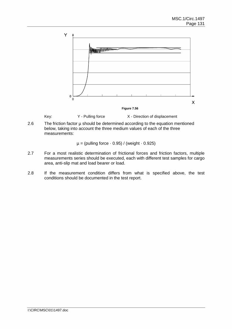
MSC.1/Circ.1497 Page 131
I:\CIRC\MSC\01\1497.doc
Figure 7.56
Key: Y - Pulling force X - Direction of displacement
2.6 The friction factor µ should be determined according to the equation mentioned below, taking into account the three medium values of each of the three measurements:
µ = (pulling force · 0.95) / (weight · 0.925)
2.7 For a most realistic determination of frictional forces and friction factors, multiple
measurements series should be executed, each with different test samples for cargo area, anti-slip mat and load bearer or load.
2.8 If the measurement condition differs from what is specified above, the test
conditions should be documented in the test report.

MSC.1/Circ.1497 Page 132
I:\CIRC\MSC\01\1497.doc
Appendix 4. Specific packing and securing calculations 1 Resistivity of transverse battens The attainable resistance forces F of an arrangement of battens may be determined
by the formula (see also figure 7.57):
L28
hwnF
2
[kN]
n = number of battens
w = thickness of battens [cm]
h = height of battens [cm]
L = free length of battens [m]
Figure 7.57 Transverse battens in an freight container
2 Bedding a concentrated load in a general purpose freight container or on a flatrack Bedding arrangements for concentrated loads in general purpose freight containers
and on flatracks should be designed in consultation with the CTU operator.
Example:
A fence of six battens has been arranged. The battens have a free length L = 2.2 m and the cross section w = 5 cm, h = 10 cm. The total attainable resistance force is:
242.228
1056
L28
hwnF
22
kN
This force of 24 kN would be sufficient to restrain a cargo mass (m) of 7.5 t, subjected to accelerations in sea area C with 0.4 g longitudinally (cx) and 0.8 g vertically (cz). The container is stowed longitudinally. With a friction factor between cargo and container floor of µ = 0.4 the following balance calculation shows:
cx · m · g < µ · m · (1-cz) · g + F [kN]
0.4 · 7.5 · 9.81 < 0.4 · 7.5 · 0.2 · 9.81 + 24 [kN]
29 < 6 + 24 [kN]
29 < 30 [kN]

MSC.1/Circ.1497 Page 133
I:\CIRC\MSC\01\1497.doc
Example:
A 20-foot container is packed with five groups of cargo parcels as follows:
2.8518.5
52.78
nm
)n
dn
(md
m
3 Longitudinal position of the centre of gravity of cargo The longitudinal position of the centre of gravity of the cargo should be used in
connection with specific load distribution rules and diagrams of CTUs26. The longitudinal position of the centre of gravity of the cargo within the inner length of a packed CTU is at the distance d from the front, obtained by the formula (see also figure 7.58):
n
nn
m
)d(md
d = distance of common centre of gravity of the cargo from the front of stowage area [m]
mn = mass of the individual packages or overpack [t]
dn = distance of centre of gravity of mass mn from front of stowage area [m]
Figure 7.58 Determination of longitudinal centre of gravity
26 Examples of load distribution diagrams for vehicles are given in section 3.1 of this annex and examples of
load distribution diagrams for containers, trailer and railway wagons are provided in informative material IM6 (available at www.unece.org/trans/wp24/guidelinespackingctus/intro.html).
mn [t] dn [m] mn · dn [t·m]
1 3.5 0.7 2.45
2 4.2 1.4 5.88
3 3.7 3.0 11.10
4 2.2 3.8 8.36
5 4.9 5.1 24.99
mn = 18.5 (mn · dn) = 52.78

MSC.1/Circ.1497 Page 134
I:\CIRC\MSC\01\1497.doc
4 Cargo securing with dunnage bags 4.1 Introduction 4.1.1 Accelerations in different directions during transport may cause movements of
cargo, either sliding or tipping. Dunnage bags, or air bags, used as blocking devices may be able to prevent these movements.
4.1.2 The size and strength of the dunnage bag are to be adjusted to the cargo weight so
that the permissible lashing capacity of the dunnage bag, without risk of breaking it, is larger than the force the cargo needs to be supported with:
FDUNNAGE BAG ≥ FCARGO
4.2 Force on dunnage bag from cargo (FCARGO) 4.2.1 The maximum force, with which rigid cargo may impact a dunnage bag, depends on
the cargo's mass, size and friction against the surface and the dimensioning accelerations according to the formulas below:
Sliding: Tipping:
FCARGO = m · g · (cx,y – µ · 0.75 · cz) [kN] FCARGO = m · g · (cx,y – bp/hp · cz) [kN]
FCARGO = force on the dunnage bag caused by the cargo [t]
m = mass of cargo [t]
cx,y = Horizontal acceleration, expressed in g, that acts on the cargosideways or in forward or backward directions
cz = Vertical acceleration that acts on the cargo, expressed in g
µ = Friction factor for the contact area between the cargo and the surface or between different packages
bp = Package width for tipping sideways, or alternatively the length of the cargo for tipping forward or backward
hp = package height [m]
4.2.2 The load on the dunnage bag is determined by the movement (sliding or tipping) and the mode of transport that gives the largest force on the dunnage bag from the cargo.
4.2.3 Only the cargo mass that actually impacts the dunnage bag should be used in the
above formulas. If the dunnage bag is used to prevent movement forwards, when breaking for example, the mass of the cargo behind the dunnage bag should be used in the formulas.
4.2.4 If the dunnage bag instead is used to prevent movement sideways, the largest total
mass of the cargo that either is on the right or left side of the dunnage bag should be used, that is, either the mass m1 or m2 (see figure 7.59).

MSC.1/Circ.1497 Page 135
I:\CIRC\MSC\01\1497.doc
m1 m2
Figure 7.59 Equal height packages
b1
b2
h1
h2
m1
m2
Figure 7.60 Unequal height packages
4.2.5 In order to have some safety margin in the calculations, the lowest friction factor should be used, either the one between the cargo in the bottom layer and the platform or between the layers of cargo.
4.2.6 If the package on each side of the dunnage bag has different forms, when tipping
the relationship between the cargo width and height of the cargo stack that has the smallest value of bp / hp is chosen.
4.2.7 However, in both cases the total mass of the cargo that is on the same side of the
dunnage bag should be used, that is, either the mass m1 or m2 in figure 7.60. 4.3 Permissible load on the dunnage bag (FDB) 4.3.1 The force that the dunnage bag is able to take up depends on the area of the
dunnage bag which the cargo is resting against and the maximum allowable working pressure. The force of the dunnage bag is calculated from:
FDB = A · 10 · g · PB · SF [kN]
FDB = force that the dunnage bag is able to take up without exceeding the maximum allowable pressure (kN)
PB = bursting pressure of the dunnage bag [bar]
A = contact area between the dunnage bag and the cargo [m2]
SF = safety factor
0.75 for single use dunnage bags
0.5 for reusable dunnage bags
4.4 Contact area (A) 4.4.1 The contact area between the dunnage bag and the cargo depends on the size of
the bag before it is inflated and the gap that the bag is filling. This area may be approximated by the following formula:
A = (bDB - π · d/2) · (hDB - π · d/2)
bDB = width of dunnage bag [m]
hDB = height of dunnage bag [m]
A = contact area between the dunnage bag and the cargo [m2]
d = gap between packages [m]
π = 3.14

MSC.1/Circ.1497 Page 136
I:\CIRC\MSC\01\1497.doc
4.5 Pressure in the dunnage bag 4.5.1 Upon application of the dunnage bag it is filled to a slight overpressure. If this
pressure is too low there is a risk that the dunnage bag may come loose if the ambient pressure is rising or if the air temperature drops. Conversely, if the filling pressure is too high there is a risk of the dunnage bag bursting or damaging the cargo if the ambient pressure decreases, or if the air temperature rises.
4.5.2 The bursting pressure (PB) of a dunnage bag depends on the quality and size of the
bag and the gap that it is filling. The pressure exerted on a dunnage by the cargo forces should never be allowed to approach bursting pressure of the bag because of the risk of failure. A safety factor should, therefore, be incorporated and, if necessary, a dunnage bag with a higher bursting pressure selected.

MSC.1/Circ.1497 Page 137
I:\CIRC\MSC\01\1497.doc
B
n ∙ H
L
H
Appendix 5. Practical inclination test for determination of the efficiency of cargo securing arrangements
1 The efficiency of a securing arrangement can be tested by a practical inclining test
in accordance with the following description. 2 The cargo (alternatively one section of the cargo) is placed on a road vehicle
platform or similar and secured in the way intended to be tested. 3 To obtain the same loads in the securing arrangement in the inclining test as in
calculations, the securing arrangement should be tested by gradually increasing the inclination of the platform to an angle, α, in accordance with the diagram below.
4 The inclination angle that should be used in the test is a function of the horizontal acceleration cx,y for the intended direction (forward, sideways or backward) and the vertical acceleration cz.
(a) To test the efficiency of the securing arrangement in the lateral direction, the greatest of the following test angles should be used:
The angle determined by the friction factor µ (for the sliding effect), or
The angle determined by the ratio of (for the tilting effect).
(b) To test the efficiency of the securing arrangement in the longitudinal direction, the greatest of following test angles should be used:
The angle determined by the friction factor µ (for the sliding effect), or
The angle determined by the ratio of (for the tilting effect).
5 The lowest friction factor, between the cargo and the platform bed or between packages if over-stowed should be used. The definition of H, B, L and n is according to the sketches in figures 7.61 and 7.62.
Figure 7.61
Figure 7.62
Package or section with the centre of gravity close to its geometrical centre (L/2, B/2, H/2). The number of loaded rows, n, in above section is 2. L is always the length of one section also when several sections are placed behind each other.
Package with the centre of gravity away from its geometrical centre.
The required test angle α as function of cx,y (0.8 g, 0.7 g and 0.5 g ) as well as µ, Hn
B
andH
L when cz is 1.0 g is taken from the diagram shown in figure 7.63 or from the table
below.
n = 2

MSC.1/Circ.1497 Page 138
I:\CIRC\MSC\01\1497.doc
Figure 7.63
In the table below the inclination α is calculated for different γ factors at the horizontal accelerations (cx,y = 0.8 g, 0.7 g and 0.5 g and cz = 1.0 g).
The γ factor is defined as follows:
µ, B/(n · H) and L/H, as required in section 4 of this appendix.
ah γ factor
0.8 g 0.7 g 0.5 g
Required test angle α in degrees
0.00 53.1 44.4 30.0 0.05 51.4 3.3 29.6 0.10 49.9 42.4 29.2 0.15 48.5 41.5 28.8 0.20 47.3 40.7 28.4 0.25 46.3 39.9 28.1 0.30 45.3 39.2 27.7 0.35 44.4 38.6 27.4 0.40 43.6 38.0 27.1 0.45 42.8 37.4 26.8 0.50 42.1 36.9 26.6 0.55 41.5 36.4 26.3 0.60 40.8 35.9 26.0 0.65 40.2 35.4 25.8 0.70 39.7 35.0 25.6 0.75 39.2 34.6 25.3 0.80 38.7 34.2 25.1 0.85 38.2 33.8 24.9 0.90 37.7 33.4 24.7 0.95 37.3 33.1 24.5 1.00 36.9 32.8 24.3
0º
10º
20º
30º
40º
50º
60º
70º
80º
90º
0.0 0.1 0.2 0.3 0.4 0.5 0.6 0.7 0.8 0.9 1.0
µ, B/(n · H) and L/H
Test angle α [º] Cx,y = 0.8
Cy = 0.7
Cx,y = 0.5
c x,y = 0.8 g
c x,y = 0.7 g
c x,y = 0.5 g
Example:
If µ and Hn
B
is 0.3 at accelerations sideways at transport in sea area B (cy = 0.7 g) the
cargo securing arrangement should be able to be inclined to approximately 39º, according to the diagram.

MSC.1/Circ.1497 Page 139
I:\CIRC\MSC\01\1497.doc
6 The securing arrangement is regarded as complying with the requirements if the cargo is kept in position with limited movements when inclined to the prescribed inclination α.
7 The test method will subject the securing arrangement to stresses and great care
should be taken to prevent the cargo from falling off the platform during the test. If large masses are to be tested the entire platform should be prevented from tipping as well.
Figure 7.64
Figure 7.65
8 Figure 7.64 and figure 7.65 show tests to confirm the securing arrangements of a
large package for acceleration forces in longitudinal and transverse directions.

MSC.1/Circ.1497 Page 140
I:\CIRC\MSC\01\1497.doc
Annex 8. Access to tank and bulk tops, working at height 1 Risk Assessment Before accessing tank and bulk CTU tops, management of the packing and
unpacking facilities and the transport companies should undertake a thorough risk assessment of the practices. Such assessments should cover:
1.1 Competence of operators Operators should be fit for duty, having successfully completed all the training
necessary to fulfil the legislative requirements and site requirements, in particular regarding the handling of dangerous goods.
1.2 Site Instructions
Site access requirements should be communicated to the hauliers and safety procedures communicated to the drivers upon arrival. Management should promote safety awareness and emphasize that it should be maintained, particularly during product handling. Management should ensure that loading/unloading operations are carried out under supervision.
1.3 Working at height Safe conditions for working at heights should be provided, as discussed in section 3
of this annex. 1.4 Product Quality The preferred option is product acceptance on the basis of a Certificate of Analysis.
Taking samples from CTUs should be avoided. If the taking of samples is absolutely necessary, management should ensure that sampling is done by qualified site personnel or by appointed surveyors with adequate safety precautions taken.
1.5 Emergency preparedness Necessary site safety equipment should be available at the loading and unloading
locations, e.g.: fire extinguisher(s), eye wash, safety shower, first aid equipment, emergency escape routes, emergency stop, decontamination equipment, and absorbent materials.
1.6 Near miss and incident reporting There should be a procedure to report all near misses, incidents, loading/discharge
problems and unsafe situations or conditions, including follow-up. There should be a system in place to share information on important near misses, incidents or unsafe situations with all parties involved.
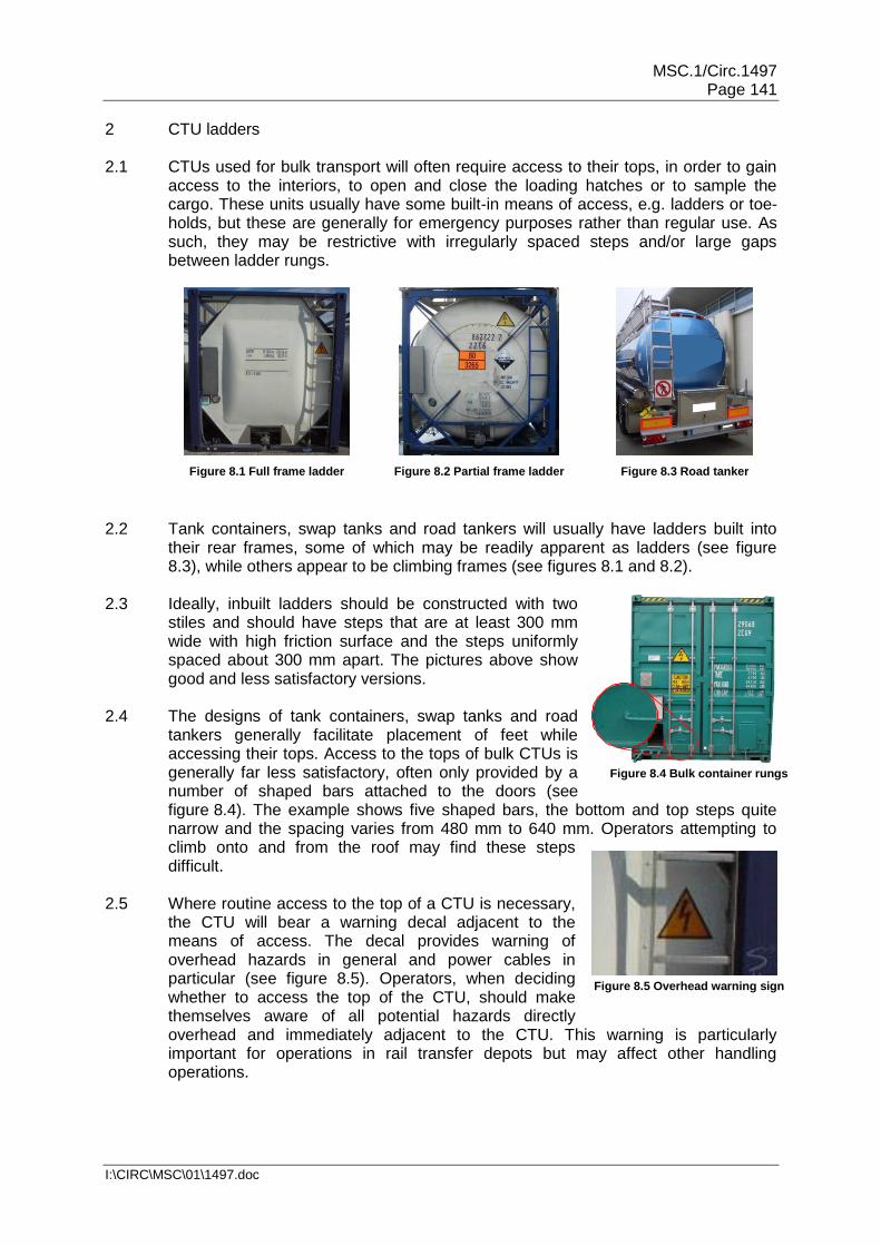
MSC.1/Circ.1497 Page 141
I:\CIRC\MSC\01\1497.doc
2 CTU ladders 2.1 CTUs used for bulk transport will often require access to their tops, in order to gain
access to the interiors, to open and close the loading hatches or to sample the cargo. These units usually have some built-in means of access, e.g. ladders or toe-holds, but these are generally for emergency purposes rather than regular use. As such, they may be restrictive with irregularly spaced steps and/or large gaps between ladder rungs.
Figure 8.1 Full frame ladder
Figure 8.2 Partial frame ladder
Figure 8.3 Road tanker
2.2 Tank containers, swap tanks and road tankers will usually have ladders built into their rear frames, some of which may be readily apparent as ladders (see figure 8.3), while others appear to be climbing frames (see figures 8.1 and 8.2).
2.3 Ideally, inbuilt ladders should be constructed with two
stiles and should have steps that are at least 300 mm wide with high friction surface and the steps uniformly spaced about 300 mm apart. The pictures above show good and less satisfactory versions.
2.4 The designs of tank containers, swap tanks and road
tankers generally facilitate placement of feet while accessing their tops. Access to the tops of bulk CTUs is generally far less satisfactory, often only provided by a number of shaped bars attached to the doors (see figure 8.4). The example shows five shaped bars, the bottom and top steps quite narrow and the spacing varies from 480 mm to 640 mm. Operators attempting to climb onto and from the roof may find these steps difficult.
2.5 Where routine access to the top of a CTU is necessary,
the CTU will bear a warning decal adjacent to the means of access. The decal provides warning of overhead hazards in general and power cables in particular (see figure 8.5). Operators, when deciding whether to access the top of the CTU, should make themselves aware of all potential hazards directly overhead and immediately adjacent to the CTU. This warning is particularly important for operations in rail transfer depots but may affect other handling operations.
Figure 8.4 Bulk container rungs
Figure 8.5 Overhead warning sign

MSC.1/Circ.1497 Page 142
I:\CIRC\MSC\01\1497.doc
2.6 As the process of climbing onto the top of a CTU entails risks of slipping and falling, a built-in ladder should only be used for emergency access. Operational access to tank container tops should be made using suitable mobile steps or from a gantry.
2.7 When a tank or dry bulk CTU is loaded onto a chassis, the bottom of the ladder can
be as much as 1,600 mm, and the top of the CTU as much as 4.3 m off the ground. Furthermore on some designs of chassis, the CTU will be slightly inclined with the front end elevated which would mean that the ladder would be inclined backwards towards to the operator.
2.8 The steps/rungs are generally manufactured from steel or aluminium and can be
slippery in the cold and wet. Operators can easily miss their step when climbing these ladders.
2.9 When transitioning from the ladder to the walkway on the CTU top, there are limited
hand holds available for the operator to grip (see figure 8.6) making the manoeuvre hazardous. An operator climbing onto the top of the tank container shown in figure 8.7 will be presented with either the walkway securing bracket or the miss-stacking plate, neither of which are ideal handholds. Climbing off the top of the CTU can be more hazardous as the operator is attempting to locate rungs/steps which are not visible and in an awkward position.
Figure 8.6 Freight container handhold
Figure 8.7 Transitioning
3 Working at height safety
3.1 Typical health and safety regulations provide that every employer ensure that work is not carried out at height where it is reasonably practicable to carry out the work safely otherwise than at height. Where work is carried out at height, every employer should take suitable and sufficient measures to prevent, so far as is reasonably practicable, any person falling a distance liable to cause personal injury.
3.2 The measures should include: 3.2.1 Ensuring that the work is carried out:
From an existing place of work; or
(In the case of obtaining access or egress) using an existing means, which complies with guidelines with those regulations, where it is reasonably practicable to carry it out safely and under appropriate ergonomic conditions; and

MSC.1/Circ.1497 Page 143
I:\CIRC\MSC\01\1497.doc
Where it is not reasonably practicable for the work to be carried out in accordance with the previous paragraph, sufficient work equipment should be provided to prevent, so far as is reasonably practicable, a fall occurring.
3.2.2 Where the measures taken do not eliminate the risk of a fall occurring, every
employer should, so far as it is reasonably practicable, provide sufficient work equipment to minimize:
The distance and consequences; or
Where it is not reasonably practicable to minimize the distance, the consequences, of a fall; and
Without prejudice to the generality of section 3.2, provide such additional training and instruction or take other additional suitable and sufficient measures to prevent, so far as is reasonably practicable, any person falling a distance liable to cause personal injury.
3.3 The regulations can generally be interpreted to mean that wherever possible working at height should be avoided, but where that is not possible, then it should be made as safe as possible by providing facilities and equipment to minimize the risk of injury (see figure 8.8).
4 Access and safety equipment 4.1 Where regular access to the top of CTUs is required, alternative access solutions
should be considered. Some operators have provided more substantial access ladders attached to trailers as shown in figure 8.9. This type of ladder satisfies the step dimension recommendation and can be adjusted so that the lowest step is just off the ground. However there are no guard rails on the ladder or on the work platform so the operator may still be at risk of a fall. As an alternative, mobile steps similar to those shown in figure 8.10 can be used which can be positioned beside the CTU and from which the operator can safely step.
Duty holder
should
Avoid work at height where they can;
Use work equipment or other measures to prevent
falls where they cannot avoid working at height; and
Where they cannot eliminate the risk of a fall, use work equipment or other
measures to minimise the distance and consequences of a fall should one occur.
Figure 8.8 Regulations hierarchy

MSC.1/Circ.1497 Page 144
I:\CIRC\MSC\01\1497.doc
Figure 8.9 Trailer mounted access ladder
Figure 8.10 Mobile access ladder
4.2 At facilities where regular access is required the CTU should be positioned next to a fixed access gantry (see figure 8.11). Once the CTU is positioned next to the gantry the operator can lower the counterbalanced handrail/barrier to provide additional safety while working on the CTU top.
4.3 If the CTU is mounted on a chassis, the operator
should not attempt to access the top of the CTU unless the tractor unit has been disconnected or immobilized to prevent accidental movement of the CTU.
4.4 A fall arrest system may be the best item of
personnel safety equipment that can be employed. Operators should wear an approved harness and attach themselves to the overhead cables. In figure 8.12 a number of "T" shaped stanchions are positioned about the area where an operator will work on the top of the container. The connecting overhead cables have counterbalanced arrest drums supported from them to which the operator will attach a harness.
4.5 The top of the CTU should not be overcrowded. The walkways are limited in size
and strength. Furthermore with too many people on the top of the CTU moving about can be hazardous.
Figure 8.11 Access gantry
Figure 8.12 Fall arrest stanchions

MSC.1/Circ.1497 Page 145
I:\CIRC\MSC\01\1497.doc
Annex 9. Fumigation 1 General 1.1 Fumigation is a method of pest control that completely fills an area with gaseous
pesticides - or fumigants - to suffocate or poison the pests within. It is utilized for control of pests in buildings (structural fumigation), soil, grain, and produce, and is also used during processing of goods to be imported or exported to prevent transfer of exotic organisms. This method also affects the structure itself, affecting pests that inhabit the physical structure, such as woodborers and drywood termites.
1.2 Timber products used for dunnage can be treated by fumigation under the
requirements of the International Standards for Phytosanitary Measures, No. 15 (ISPM 15)27. Some shippers believe, incorrectly, that they can achieve this by throwing in a fumigation bomb just before the CTU doors are closed. This, however, is not permitted under ISPM 15 and does not achieve the required level of treatment.
1.3 Fumigated CTUs containing no other dangerous goods are subject to a number of
provisions of dangerous goods regulations, such as those included in this annex28. 1.4 When the fumigated CTU is packed with dangerous goods in addition to fumigant,
any provision of the dangerous goods regulations (including placarding, marking and documentation) applies in addition to the provisions of this annex.
1.5 Only CTUs that can be closed in such a way that the escape of gas is reduced to a
minimum should be used for the transport of cargo under fumigation. 2 Training Persons engaged in the handling of fumigated CTUs should be trained
commensurate with their responsibilities. 3 Marking and placarding 3.1 A fumigated CTU should be marked with a warning mark (see figure 9.1) affixed at
each access point in a location where it will be easily seen by persons opening or entering the CTU. This mark should remain on the CTU until the following provisions have been met:
The fumigated CTU has been ventilated to remove harmful concentrations of fumigant gas; and
The fumigated goods or materials have been unpacked.
27 Secretariat of the International Plant Protection Convention, Food and Agriculture Organization of the
United Nations: Regulation of wood packaging material in international trade. 28 See also the latest edition of the UN Recommendations on the Transport of Dangerous Goods, Model
Regulations at www.unece.org/trans/danger/publi/unrec/rev13/13nature_e.html, or modal transport regulations such as the IMDG Code.

MSC.1/Circ.1497 Page 146
I:\CIRC\MSC\01\1497.doc
3.2 The fumigation warning mark should comply with the relevant dangerous goods regulations. Below is the fumigation warning mark as shown in the 18th revised edition of the United Nations Recommendations on the Transport of Dangerous Goods, Model Regulations.
Figure 9.1 Fumigation warning mark
4 Ventilation 4.1 After the fumigant has performed its function it can be ventilated before it is
transported if required. When the fumigated CTU has been completely ventilated either by opening the doors of the CTU or by mechanical ventilation after fumigation, the date of ventilation should be marked on the fumigation warning mark.
4.2 Care should be taken even after a CTU has been declared as ventilated. Gas can
be held in packages of cargo, then desorbed over a long period of time, even over many days, raising the level of gas inside the cargo transport unit to above the safe exposure level. Bagged cereals and cartons with large air spaces are likely to produce this effect. Alternatively, gas and the fumigant sachets or tablets can become 'trapped' at the far end of a CTU by tightly packed cargo.
4.3 In reality any CTU that has carried dangerous or fumigated goods should not be
considered as safe until it has been properly cleaned and all cargo residues, gaseous and solid, have been removed. The consignee for such goods should have the facilities to carry out this cleaning process safely.
4.4 When the fumigated CTU has been ventilated and unpacked, the fumigation
warning mark should be removed.
* Insert details as appropriate
DANGER
THIS UNIT IS UNDER FUMIGATION
WITH ( fumigant name* ) APPLIED ON ( date* ) ( time* ) VENTILATED ON ( date* )
DO NOT ENTER
Minimum dimension 400 mm
Min
imum
dim
ensi
on 3
00 m
m

MSC.1/Circ.1497 Page 147
I:\CIRC\MSC\01\1497.doc
Annex 10. Topics for consideration in a training programme
Topics to be included in a training programme
1 Consequences of badly packed and secured cargo
Injuries to persons and damage to the environment
Damage to all means of transport and CTUs
Damage to cargo
Economic consequences
2 Liabilities
Different parties involved in cargo transport
Legal responsibility
Goodwill responsibility
Quality assurance
3 Forces acting on the cargo during transport
Road transport
Rail transport
Sea transport
4 Basic principles for cargo packing and securing
Prevention from sliding
Prevention from tipping
Influence of friction
Basic principles for cargo securing
Dimensions of securing arrangements for combined transport
5 CTUs – types
Freight containers
Flats
Swap bodies
Road vehicles
Rail cars/wagons
6 Cargo care consciousness and cargo planning
Choice of transport means
Choice of CTU type
Check of CTU prior to packing
Cargo distribution in CTUs
Requirements from the receiver of cargo regarding cargo packing
Condensation risks in CTUs
Symbols for cargo handling
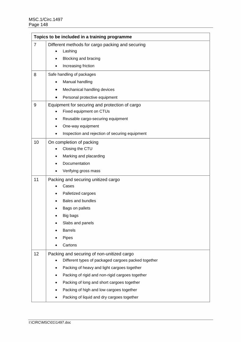
MSC.1/Circ.1497 Page 148
I:\CIRC\MSC\01\1497.doc
Topics to be included in a training programme
7 Different methods for cargo packing and securing
Lashing
Blocking and bracing
Increasing friction
8 Safe handling of packages
Manual handling
Mechanical handling devices
Personal protective equipment
9 Equipment for securing and protection of cargo
Fixed equipment on CTUs
Reusable cargo-securing equipment
One-way equipment
Inspection and rejection of securing equipment
10 On completion of packing
Closing the CTU
Marking and placarding
Documentation
Verifying gross mass
11 Packing and securing unitized cargo
Cases
Palletized cargoes
Bales and bundles
Bags on pallets
Big bags
Slabs and panels
Barrels
Pipes
Cartons
12 Packing and securing of non-unitized cargo
Different types of packaged cargoes packed together
Packing of heavy and light cargoes together
Packing of rigid and non-rigid cargoes together
Packing of long and short cargoes together
Packing of high and low cargoes together
Packing of liquid and dry cargoes together

MSC.1/Circ.1497 Page 149
I:\CIRC\MSC\01\1497.doc
Topics to be included in a training programme
13 Packing and securing of paper products
General guidelines for the packing and securing of paper products
Vertical rolls
Horizontal rolls
Sheet paper on pallets
14 Packing and securing of cargo requiring special techniques
Steel coils
Cable drums
Wire rolls
Steel slabs
Steel plates
Big pipes
Stone blocks
Machines
15 Packing and securing of dangerous cargoes
Regulations for the transport of dangerous goods
Definitions
Packing regulations
Packing, separation and securing
Labelling and placarding
Information transfer when transporting dangerous cargoes
Liabilities
___________

![Sectoral Activities Department ILO/IMO/JMS/2011/13 · ILO-IMO-JMS-FR-[2011-09-0260-10]-En.docx/v4 1 Introduction 1. A meeting of the Joint ILO/IMO Meeting on Medical Fitness Examinations](https://img.dokumen.tips/doc/110x75/604a338584a42d4f8158a638/sectoral-activities-department-iloimojms201113-ilo-imo-jms-fr-2011-09-0260-10-endocxv4.jpg)