Embed Size (px)
Citation preview

g REPIR EVXMiTION HAINTEWNCE ID REHMSILITATIOU hRESECH PROWAN STATE 0 C(U) UOROXA INST OF TECHATLMTA SCHOOL OF CIVIL ENGINEERING R D SCSDALE
r7NCRSII~DNOV 0? IES.'TL'L-RMI-OT-4 0AC39-SS-M-2359 F.'O W2 IL
IMENMhhhhIL m mhhh
1 132 _
111111202
1111W12 111111'.4 .6
MICROCOPY RESOLuTION ILSI CI-ARTNAN NA I H RAl 11 !
S~~ S 5 5 U w w w= w

97]] FILE COPM ii~
REPAIR, EVALUATION, MAINTENANCE, ANDREHABILITATION RESEARCH PROGRAM
o TECHNICAL REPORT REMR-GT-4
STATE OF THE ART FOR DESIGNAND CONSTRUCTION OF SAND
COMPACTION PILESby
Richard D. Barksdale
School of Civil EngineeringGeorgia Institute of Technology
Atlanta, Georgia 30332
00
0000
?-W
November 1987 ".Final Report
Approved For Public Release, Distribution Unlimited 0
DTICELEL;TE'
~JAN 2 5 988Ld
Prepared for DEPARTMENT OF THE ARMYUS Army Corps of EngineersWashington, DC 20314-1000 .-
S "Under Civil Works Research Work Unit 32275
Monitored by Geotechnical LaboratoryAM US Army Engineer Waterways Experiment Station
PO Box 631, Vicksburg, Mi ippi 39180-0631

The following two letters used as part of the number designating technical reports of research published under the Repair,Evaluation, Maintenance, and Rehabilitation (REMR) Research Program identify the problem area under which the report wasprepared:
Problem Area Problem Area
CS Concrete and Steel Structures EM Electrical and Mechanical d"
GT Geotechnical El Environmental Impacts
HY Hydraulics OM Operations Management "
CO Coastal
For example. Technical Report REMR-GT-4 is the fourth report published under the Geotechnical problem area.
Destroy this report when no longer needed. Do not returnit to the originator.
.o.
The findings in this report are not to be construed as an officialDepartment of the Army position unless so designated
by other authorized documents.
The contents of this report are not to be used foradvertising, publication, or promotional purposes.Citation of trade names does not constitute anofficial endorsement or approval of the use ofsuch commercial products. d
S
COVER PHOTOS. -
TOP -Typical Sand Compaction PileConstructionEquipment.BOTTOM - Typical Equipment Used To ConstructMammoth Compaction Poles Over Water.
Eq ip en. ...
Mammo, .4 thrJ A J Copcto Pole Ove Wae .. .y. .. . ... . .-

,i S.-'%
,." 4,'. ,
.'.
Unclassified A 0O /
SECURITY CLASSIFICATION OF THIS PAGE
Form, APPo~edREPORT DOCUMENTATION PAGE OMBNo 0104 08 .0 7
ExP Date Jun30 1986 ' 'la REPORT SECURITY CLASSIFICATION lb RESTRICTIVE MARKINGSln l as stf ied .-________________________ P'- *.
2a SECURITY CLASSIFICATION AUTHORITY 3 DISTRIBUTION/AVAILABILITY OF REPORT *
2b DECLASSIFtCATION/DOWNGRADING SCHEDULE Approved for public release; distributionunlimited
4 PERFORMING ORGANIZATION REPORT NUMBER(S) 5 MONITORING ORGANIZATION REPORT NUMBER(S)
Technical Report REMR-CT-46a NAME OF PERFORMING ORGANIZATION I6b OFFICE SYMBOL 7a NAME OF MONITORING ORGANIZATION
(if applicable) USAEWES
Georgia Institute of Technology Geotechnical Laboratory&. ADDRESS (City, State,. and ZIPCode) 7b ADDRESS (City. State. and ZIP Code)
PO Box 631 .
Atlanta, CA 30332 Vicksburg, MS 39180-0631Ba, NAME OF FUNDING/SPONSORING 8b OFFICE SYMBOL 9 PROCUREMENT INSTRUMENT IDENTIFICATION NUMBER .*'."
ORGANIZATION (If applicable)
US Army Corps of Engineers DACW39-85-M-2358Bc. ADDRESS (City, State, and ZIP Code) 10 SOURCE OF FUNDING NUMBERS
PROGRAM PROJECT TASK WORK UNITELEMENT NO NO NO ACCESSION NO
Washington, DC 20314-1000 32275
I1 TITLE (Include Security Classification)
State of thu Art for Design and Construction of Sand Compaction Piles
12 PERSONAL AUTHOR(S)
Barksdale, Richard D.
13a TYPE OF REPORT I3 b TIME COVERED 14 DATE OF REPORT (Year. Month. Day) 15 PAGE COUNT
Final report FROM_ TO November 1987 5716 SUPPLEMENTARY NOTATION A report of the Geotechnical problem area of the Repair, Evaluation,Maintenance and Rehabilitation (REMR) Research Program. This report is available from theNational Technical information Service, 5285 Port Royal Road, Springfield, VA 22161.17 COSATI CODES 18 SUBJECT TERMS (Continue on reverse if necessary and identify by block number)
FIELD GROUP SUB GROUP ">In-situ deep compaction, Remedial treatments,
Liquefaction SoilsPore-water pressure. Pool reinforcement
[9 A TRACT (Continue on reverse if necessary and identify by block number)
Sand compaction piles can be used to improve marginal sites for stability, liquefac-tion, and settlement applications. They have been employed extensively in Japan for manyyears to improve land reclaimed from the sea. The advantages and disadvantages of usingsand compaction piles are compared with other vibro-compaction techniques such as stonecolumns. Methods are described for construction of sand compaction piles on land and overwater.
Design theories are given for the utilization of sand compaction piles at sites under-lain by both cohesionless and cohesive soils. For sites underlain by cohesionless sands,procedures are presented for estimating the increase in standard penetration resistance inboth tlse sand compaction pile and the surrounding sand. Techniques are described for esti- 'a
mating stability and one-dimensional consolidation settlement of sites underlain by cohesivesoils that have been improved with sand compaction piles. Finally, typical applications of "'..sand compaction piles are described, and practical design criteria and practices are given., ,
20) DISTRIBtU1IONAVAILARItITY O1 ARSTI/A( Ail'RA( 'F/r W' AS;, O[' UNCtASSIFIED),hNLIMITFD [ SAVE AS QPT [] or S1 I Unc lass if led
22a NAME OF RFESPONSI{i INDIV00AL '. "/.I (I lr Ar,,oe ( .'. 'i t 'V/- ,
DOFORM 1473, 8aMAR ,,,.,, 'n., ,, , .. ,,,,.,,;" .Ac,,,A,/' , " 'IAl , S, i '. ' [Inv lass if ted
" . .., .- - .,.4.a • , , -."., .'"" .•-... -"-..'.v...-. ." ... , . , -. ,,..' .-." -**.'* ""- .'-*''---*~a**-. ***"-'_*v .'. ,a,"-

I ~~uu u ~ 1 V U V FV VWUV WV W1iWV rw WV w I(R 'A WITL Wz Wil JV1 VVYV I -. 'jw yly I NN*",
.1*
PREFACE
The original research for this report was performed for the US Depart-
ment of Transportation, Federal Highway Administration, under a contract to
the School of Civil Engineering, Georgia Institute of Technology. The final
report presented herein was prepared under Contract No. DACW39-85-M-2358 with
the US Army Engineer Waterways Experiment Station (WES) during the period
July 1985 to December 1986. The investigation was conducted under the Repair,
Evaluation, Maintenance, and Rehabilitation (REMR) Research Program Work
Unit 32275, "Remedial Improvement of Liquefiable Foundations." Mr. Authur H.
Walz, Headquarters, US Army Corps of Engineers (iQUSACE), was REMR Technical
Monitor.
The REMR Overview Committee, consisted of Mr. John R. Mikel
(DAEN-CWO-M), Mr. Bruce L. McCartney (DAEN-CWH-D), and Dr. Tony C. Liu
(DAEN-ECE-D). Coordinator for the Directorate of Research and Development
was Mr. Jesse A. Pfeiffer, Jr. (DAEN-RDC), and the REMR Program Manager
was Mr. William F. McCleese, Concrete Technology Division, Structures
Laboratory, WES
Appreciation is expressed to the Federal Highway Administration for grant-
ing special permission to allow the publishing of this report. Mr. A. F.
DiMillio was project manager, and Mr. Jerry DiMaggio was Technical Monitor for
the Federal Highway Administration. Mr. Richard H. Ledbetter, Earthquake
Engineering and Geophysics Division (EEGD), Geotechnical Laboratory (GL), was
Technical Monitor for the WES, under the supervision of Dr. Arley G. Franklin,
Chief, EEGD, and under the general supervision of Dr. William F. Marcuson III,
Chief, GL. Appreciation is extended for Mr. Ledbetter's help and careful
review of the manuscript. Special thanks also go to Dr. P. F. Hadala, Assis-
tant Chief, GL, for his thorough review of the manuscript.
The contents of this report reflect the views of the author who is
responsible for the facts and accuracy of the data presented herein. The
contents do not necessarily reflect the official view or policies of the US
Army Engineer Waterways Experiment Station. This report doe,4 not constitute
a standard, specification, or regulation.
The design and construction practices for sand compact ion p iles dclscribed
in this report are felt to be representative of those, present ]v toIllowed in
Japan. These practices, as described, were developed from di -&nss ions witi
% ,

Japanese and Taiwanese engineers, contractors, and equipment manufacturers
along with field inspections and a review of the literature. Thanks are given
to all the engineers and organizations, too numerous to acknowledge separately,
who made valuable contributions to this study. Special acknowledgement is
given to Mr. Tony Sullivan of Kencho, Inc. and Mr. Mizutani of Kensetsu Kikai
Chosa Co., Ltd. for making detailed arrangements for the inspection trip to
Japan and Taiwan.
COL Dwayne G. Lee, CE, is Commander and Director of WES. Dr. Robert W.
Whalin is Technical Director.
oil , Accession For 0.
NTIS CRA&IDTIC TABUnannounced ElIJustification
By_ _ _ _ _
Distribution/ _-
1 Availability Codes
Avail and/or -
Dist Special
.-
,''7% E
-:0
* ~ * * d - .~ . ? 5,

CONTENTS
PREFACE ..................................................................... 1
CONVERSION FACTORS, NON-SI TO SI (METRIC) UNITS OF MEASURFMENT. ........... 4
PART I: INTRODUCTION ....................................................... 5
Advantages and Disadvantages of Sand Compaction Piles ............... 5Sand Co- , ion Piles in Japan ........................................ 7
PART II: CONSTRUCTION OF SAND PILES ..................................... 9
Sand Compaction Pile Construction ................................... 9Strong Sand Piles ...................................................... 14Mammoth Compaction Piles ............................................ 17General Considerations .............................................. 17
PART III: DESIGN THEORY FOR SAND COMPACTION PILES ....................... 20
Introduction .......................................................... 20Area-Replacement Ratio ................................................ 20
Sites Underlain by Sand .............................................. 21Sites Underlain by Cohesive Soils ................................... '30Increase in Shear Strength Due to Consolidation ..................... .33Conclusions ............................................................ 35
PART IV: GENERAL I)ESIGN CONSIDERATIONS .................................. 3. 7
Appl icat ions ........................................................... 37General Criteria and Practices ...................................... 4()Stability Considerations .............................................. 40Stress Concentration .................................................. 44Sand Pile Gradation ................................................... 45Qua lity Control ....................................................... 4Influence of Lateral Pressure on S!T' Value. ..........................Strength Loss Due to Sand Pi le Instal liat io .........................
1)AR'T V SUMMARY AND CONCIU!SIONS ........................................... '
RIKIKR EN(:L,"...............................................................
06
'p il
'.I ii

Aq
CONVERSION FACTORS, NO TO SI (METRIC)
UNITS OF MEASUREMENT
Non-SI units of measurement used in this report can be converted to SI
(metric) units as follows: V
Multiply By To Obtain
degrees (angle) 0.01745329 radians
feet 0.3048 metres
horsepower (550 foot-pounds 745.6999 watts
(force) per second)
inches 25.4 millimetres
pounds (force) 4.448222 newtons
pounds (mass) per 16.01846 kilograms percubic foot cubic metre
pounds (mass) per 4.882428 kilograms per
square foot square metre
pounds (mass) per 0.0703 kilograms persquare inch square centimetre
tons (2,000 pounds, mass) 907.1847 kilograms
2I
4

STATE OF THE ART FOR DESIGN AND CONSTRUCTION OF
SAND COMPACTION PILES '
PART I: INTRODUCTION
1. Sand compaction piles are one potential method for improving
marginal sites for stability, liquefaction and settlement applications.
They also act as drains for static loading and accelerate primary
consolidation. Sand compaction piles have been used extensively in Japan
and Taiwan primarily for stability purposes in reclaiming land from the sea. ISand piles are similar to sand compaction piles but are not densified to as
high a degree. Sand piles have been used in the United States primarily
for sand drains to accelerate consolidation settlement but in recent years
have been generally replaced by wick drains. Sand compaction piles, as
defined in this report, have apparently not been used in the United States.
Advantages and Disadvantages of Sand Compaction Piles
2. Table 1 summarizes the advantages and disadvantages of sand
compaction piles compared with several types of stone columns. The primary
advantages of sand compaction piles over stone columns are (a) sand, which
is often considerably cheaper than stone, is used in construction, (b)
construction of the sand column is extremely fast, (c) the hole is fully
supported by a casing during construction that eliminates the possibility
of hole collapse, and (d) the possibility of intrusion and/or erosion of
surrounding soil into the sand column is significantly reduced compared with
stone columns; whether movement of particles can occur depends upon the -
gradation of both the sand compaction pile and the surrounding soil. Sand
compaction piles are a possible solution for strengthening pervious
embankment foundations found to be susceptible to liquefaction or
impervious foundations susceptible to stability problems, for example,
during an earthquake.
3. Sand compaction piles also have several important disadvantages N,
that must be carefullv considered during desi gi The primirv N
disadvantages of sand compaction piles are: (a) they have a lower angle of
5
N N %% V
A*t 'S c 'S. S*. '., j% \ .'S ,*%w M&,.'.:

ilk -1
INC
4-1D
tt
i IL
E- 4-ta 01 5 4 '
- Ca C.CC-
S CC 0CCO .. IS
410 f - -
-t. C~t - 00 C ttO .dl

•. .,
internal friction and a lower stiffness than stone columns; hence in
general a larger percentage replacement of weak soil is required using sand
compaction piles; (b) driving the casing through a clay layer causes
"smear" along the boundary of the column that reduces lateral permeability 0.,.and hence their effectiveness as a drain. Nevertheless, an important .
decrease in time for primary consolidation occurs when sand compaction --
piles are used, and (c) sand compaction piles do not have sufficiently high
permeability to function as effective vertical drains during earthquakes.
Use of a sand compaction pile would increase the relative density of-' .%
pervious native soils between the piles, the amount of improvement
depending upon the pile spacing, method of construction and other factors.
Also the strength of the sand compaction pile would increase the resistance
to failure should liquefaction occur.
Sand Compaction Piles in Japan
4. The need in Japan to reclaim extensive areas from the sea lead to '
the first construction of sand piles between 1830 and 1850 (Ichimoto, 1980). j.Early in the 20th century a technique for compacting the sand pile was
developed which was apparently somewhat similar to the process now used for
constructing Franki type concrete piles. Today, sand compaction piles are
usually constructed by driving a pipe having a special end restriction
through a loose to firm sand, or very soft to firm silt or clay stratum
using a vibrator located at the top of the pipe. Sand compaction piles
generally have a diameter varying from 24 to 32 in.,* but may be as large
as 80 in. Typically 5- to 7-ft sand compaction pile spacings are used
in Japan. During or immediately after driving, the pipe is filled with
sand. The sand is then densified by repeatedly raising and lowering the
vibrating pipe as it is withdrawn from the ground. Several modifications
of this procedure which can be described in Japanese terminology are
mammoth compaction piles and strong sand piles. Mammoth compaction piles
are quite similar to sand compaction piles except they are usually
Constructed over water using larger equipment. Strong sand piles are
* A table of factors for converting non-Sl units of measurement to SI (metric)
units presented on page 4.
,'l-.*7
%0• ' oy

wW_7T%-1 rMN F7-VWTVVIY 'W VVV J-. 77 M7~ W .
installed using the same procedure as for sand compaction piles but are.
further densified using a horizontal vibrator at the bottom of the casing.
Sand compaction piles and mammoth compaction piles are the most commn> /
used sand pile techniques in Japan for improving poor sites.
5. In Japan over 160,000,000 ft of sand compaction piles and sand
drains were constructed during the last 20 years by Fudo Construction Co.
alone; undoubtedly this is just a small fraction of the total lengthn
constructed during this time. Probably the greatest use of sand compa.ctior"
piles is to improve hydraulic sand fills and/or the underlying weak natura.-
soils. Sand compaction piles in Japan are used primarily to prevent
stability failures, decrease the time of consolidation and prevent
liquefaction failure. Sand compaction piles are also used in Japun to
reduce settlement although this appears usually to be a secondary objective
since preloading is generally utilized. The distribution of uses of sand
compaction piles by Fudo Construction Company is given in Figure 1; tnis
summary, based on the results of the fact-finding t'ip, is felt to be
generally representative of the overall use of sand compaction piles in
Japan. Over 80 percent of the sand compaction piles are used to support
stockpiles of heavy materials and various types of tanks and embankments
for roads and railways. Only 4 percent of the sand compaction piles are
used in Japan to support buildings and warehouses. The extent of us in
Japan, if any, of sand compaction piles in dams, locks and levees i.s iot
known.
HS
.
...-.-..- ,

* ' Y~WVY.T VVi I. N-V VV'.VT^, W ,-- - - - - v w ,py w - .
PART I: CONSTRUCTION OF SAND PILES
Sand Compaction Pile Construction
%. -
6. The equipment typically used to construct a cand compact, ..
is shown in Figures 2 and 3 and the coastructi oil Se(III3,IICL' in 1 i, .
For constructing sand compaction piles, a 4.5- to 6-ton h1idr.nl i,
electric vibrator is attached to the top of a l- to, 2-in. lI:i t
pipe. The pipe casing is slightly longer than the desired lent n
sand compaction pile so as to protrude out of the ground after 'e ': ;.
design depth. The pipe fully supports the surrounding soil at allr,
during construction. A description of how native soil is prevented from
entering the pipe is subsequently described in paragraph 12. Water jets
are sometimes used on the outside of the pipe when layers are encountered
that have a standard penetration test (Sl'1') resistance greatcr than :about
15 to 20. Water jet pressures up to 1200 psi have been used to aid
driving piles using vibratory hammers (H1-avashi, 1981).
7. The casing with attached vibratory hammer is suspended from a
crawler crne and is guided by leads. A 35- to 40-ton crawler crane is
used for constructing 60- to 65-ft-long sand compaction piles. A coil
spring shock absorber is fastened to the top of the vibrating hammer to
damipen the shock as the easinig is pulled from the ground by the crane.
During driving, the cable from the crane to the casing is kept slaick so that .
the p i pe-v i brat or as semh I i s free float i ng . Proper pipe al iganient is
maint inled by a guide attached to the vibritor that moves up and dlown t h(-
crane leads.
8. A low frequency, high amplitude vertical vibrator is used having a
frequency of 500 to 600 cpm and amplitude during idling of 0.6 to 0.7 in.
The amplitude is defined as one-half the total tip movement. The commonl
used vibrators are driven by 120 to 160 b' mtors Mn0 mbll . , 111,.l,1, 111, k.'l
forces varying from 90,000 to 1 35,000 1b, ,a auuwm vised i a i. ,.' . 1..- -
vibrators having greater than 120 imp ar, n:-tm,I l l, 115, ' , '. t)I,
cons t ruct ion of mammoth compact i ,)n p il e Ovr !e Vti. I , ' a' 1 ".'t
p, r~t :l~t }l )¢. ""-
., , I
A, A-AZJI

vuWj~-.-WT uw-ii.wvwg W v
Embankment for Roads and Railways --
Foundation of Harbor Structures 1
Platolend Buildings and Warehouses
Figure ~ i . ee Ditiuionoadcmpcinplsapiain
(after "Compozer System," Fudo Construction Co., Ltd., anon-
ymous (undated), Tokyo, Japan
Guide Leads
Spring Shock Absorber
Suspending w ireVibrator
Ho ppe r
Casifl. P~pe
Recorder for Oower,
P ~ ~ ~ ~ ~ ~~~~oe 1 i ai tr1n.noo 93
a~~~ ', 2~~~~....... . d E .. r. x '. . . .
Fi ur Tji'i L'-i)1C 1 S d t C IS -- 1' Ii 1

%*.
Figure 3. Photograph of typical sand
compaction pile construction equipment
used in Japan and Taiwan
Ink
lip-
Figure !4. Con, trt ion sequence tor s~iiid cornp;i-[i IIp1 1vC' (;I f t r T,] i 111( 9, 1 73)
. . . . . .."
11%

.WWWIJW WWWf~1WUU17W4.7 VWW 4*WI 11 17 VW 1W 7W ~ 4FW .T .1W11W~ VVWYWiiYWVC)~
InI
'a 00C9.
0 0o
w 141
w 0- w
0 u
0~
-4
UZ C1 I
.4-4c
F A 0 4) )to oD I 0 .
ww>4 ~ U C l 0. 0) .C l lL
> a, c.~4* -
>1 0- C:
u 0 wC Co 0 U .. W 0 0 4.- -
I.OC ' C 4 r,4 >, m
4
>r
>I4
c12

Filling steel casing
9. To minimize construction time, the steel casing is usually filled
with sand as it is being driven down so that extraction of the casing can
begin immediately upon reaching the required depth. After filling the , .
skip with a front end loader (Figure 2), the sand is mechanically lifted
and dumped into the hopper located at the top of the pipe as the pipe is
being vibrated down (Figures 2 and 3). The skip bucket is guided by the
leads suspended from the crane. This very efficient method of construction
was observed at all construction sites visited in both Japan and Taiwan.
If an automatic skip bucket is not available, the hopper at the top of the
casing can be filled using the front-end loader after it has almost reached
the required depth. This alternate approach requires less mechanical
equipment, but the sand compaction pile production rate is considerably NO,
reduced. Typical production rates are summarized in paragraph 13..
Sand removal .4v
10. Upon filling the casing with sand, a 40- to 70-psi air pressure
is applied to the top of the sand column. To develop the required air
pressure on top of the sand, a pressure of about 100 psi is developed at
the compressor. A special valve (Figure 5) is used to introduce the air
pressure to the sand yet keep the hopper sealed from the atmosphere. The
air pressure on the top of the sand prevents soft soil from flowing into
the pipe and helps to force the sand out during withdrawal. Water is
usually not utilized during the construction of a sand compaction pile. If
the sand is dry, however, contractors frequently add some water to the sand
to prevent it from sticking in the tube due to arching.
Sand densification
11. A sand compaction pile is constructed using a stroking motion of
the casing as it is withdrawn (Figure 4). The casing is first pulled up 6
to 10 ft. using the crane, and then vibrated back down 3 to 7 ft. This up-
and-down stroking motion is repeated until the casing has been completely
withdrawn from the ground. The stroking motion apparently plays an
important role in achieving a strong, dense sand compaction pile, and in
densifying the surrounding sands. As the sand compaction pile is
constructed, the depth of the casing tip, power consumption and approximate
volume of sand consumed are usually continuously recorded. If a stroking
motion is not used, the resulting column is called simply a sand pile.
13
0-o-°
++++', , "", . '+ ,'+ ,'++_+ + + -" ,",+-" .' • ++ -' ., , ,+ .,

Closing casing end during driving
12. During driving the lower end of the casing is closed using one of
the special end cover assemblies shown in Figure 6. Figure 6(a) shows the
tip used by the contractors at the sites visited in Japan and Taiwan. This
tip consists of several hinged metal fingers that are manually pushed
together to form a closed end before driving begins. As the casing is
withdrawn the fingers open out under the action of gravity (Figure 7)
allowing the sand to flow out. Fudo Construction Company uses a
constriction in the end of the pipe relying on friction and the weight of
the sand to maintain equilibrium during driving (Figure 6(b)). An end plate
hinged in the middle is also sometimes used in Japan (Figure 6(c)).
Summary
13. Construction of sand compaction piles using the equipment and pro-
cedures described in this section is fast and efficient. Using this process a
50-ft sand compaction pile can be constructed in about 20 min with average
daily production rates being about 20 piles. About 45 sand compaction piles
per day on the average can be constructed using 20-ft-long piles.
Strong Sand Piles
14. Several modifications to the basic method are sometimes used in
Japan to construct sand compaction piles. The strong sand pile method,
developed in 1973, is used in soft clays in the same way as sand compac-
tion piles.* To construct a strong sand pile, a casing is first
driven by a vertical vibrator attached to the top of the casing using
similar equipment and procedures previously described for sand compaction
piles. In constructing strong sand piles, however, a horizontal vibrator
is placed just below the bottom of the casing as shown in Figure 8.
Because of the use of the horizontal vibratory (called a Vilot) at the tip
of the casing, a higher degree of densification of the sand is reported by
Hayashi 1981 to be obtained than for sand compaction piles.
15. During or after driving of the casing, sand and water are
introduced through the sand inlet at the top of the casing (Figure 8).
Adding water to the sand in this method helps to achieve a higher density
of the sand during vibration, and also allows the sand to flow out of the
* "SVS Method Technical Information," Kenset su Kikai Chosa Co., Ltd., anon-
ymous (undated), Osaka, Japan.
14
***%.* .* -- .. . . . . .% -. .. .. - -. .- ... . -. - .. - j

Hopper Opening
for Sand Roller %~Charging -r%
Valve Seat
Inlet for air to
close valve and
press sand Jown
Valve%
Rubber Packing .
Figure 5. Special valve used to seal the casing when%air pressure is introduced
EndRestrtic tion.. . . .
................................ ..................................................
(a) Finger End (b) Restricted open End- (c) Bucket 11c PIFudo Const. Co.
Figure 6 . Mthods uiscd to prevent so il f rom enter in - NS of
du r ing d rivinug

46-i
% *
% I
VO %
Figure 7. Photo of finger end which prevents soil fromentering casing during drivig
v T
Fi~s111e S. C(1~ tri( tkii -t toi , ,; i~d ,)mp i( io

casing more easily. Sand is usually supplied to the casing using the same "4
automatic skip bucket employed for sand compaction piles. On land the skip
bucket is filled with a front-end loader. When working over water from a
barge, a belt conveyor is used to fill the bucket.
16. After filling the casing with sand, the inlet is closed and 40 to 0,
70 psi of compressed air is introduced to the top of the sand. The
vibrator at the bottom of the casing is then actuated causing a horizontal 0
and circular vibration. As the casing is gradually extracted, the lids at
the bottom of the casing open outward and sand flows out forming the pile
(Figure 8). The horizontal vibrator operates continuously during
extraction. At selected intervals extraction of the casing may be stopped
to achieve additional densification of the sand. A stroking motion during
extraction is apparently not generally used.
Mammoth Compaction Piles
17. Mammoth compaction piles are const ructod in Japan in pth,
of water up to 100 ft to provide a foU1ndation on which to rt-.' .-aim ]and
from the sea. The stabilization of very soft ocean sediments with mammoth
compaction piles is accomplished using materials and construction
techniques similar to the sand compaction piles constructed on land.
Mammoth compaction piles are routinely constructed in Japan having
diameters of 24 to 79 in. and lengths up to 160 it h low sea I ,vw .
18. From two to four mammoth compaction piles are
constructed simultaneously from a large barge such as the one shown in
Figure 9. Each casing is driven to the required tip elevation using a
large vertical vibrator. The vibrator is mounted at the top of the casingand typically driven by a 16)- to 40)-hp motor. In Vw rv soft sod i mont
the casings are sometimes pulled down by a cable rather than vibrated. The
remainder of the construction operation is similar to sand compaction piles
which have been previously described.
General Considerations
1 9. Sand pile di-imeters of .? to 47 in. are usoa lly c,)nstructed using
casing diameters of 0 to 3.2 in., and a 1 'U- t,, l!H) J , i , 1 vi , t, 0

*% *f1
* ft%
~Sl
I.e
.i,,u r . 9 . I'ho t of typ i c al equ ipmnnt tlso, d to cons t rtic t r;
manrnmoth compact ion pi]les ovc~r waltt'r -,''*.
.'.ft.
f.-'.

WKV -XW' N"- NI -V -- -V -
Sand pile diameters of 32 to 79 in. are constructed using 24- to 47-in.
casing and 160- to 400-hp vertical vibrators. A 10- to 40-hp horizontal
vibrator is sometimes used at the bottom of the casing. Table 2 gives
specifications of horizontal vibrators (Vilots) used to construct strong
sand piles. At the present time, however, the strong sand pile method is
not nearly as popular in Japan as sand compaction piles.
20. The diameter and density of both sand compaction piles and strong
sand piles can be varied by changing the (a) casing diameter, (b)
extraction rate, (c) compressed air pressure, (d) time of vibration and, (e)
size of vibrator. Further, a pile diameter varying with depth can be
obtained by changing (b) through (d) during casing extraction. During
construction the diameter of the sand pile, volume of sand supplied and
discharged, casing tip elevation, and the power (amps) used by the vibrator
are frequently all automatically recorded.
%@n .]

-"W .1 .V 1 W% .V VV - - ' -S
PART III: DESIGN THEORY FOR SAND COMPACTION PILES
Introduction
21. In this section the theory for designing sand compaction piles
and mammoth compaction piles is presented as presently followed in Japan.
Sites underlain by both sand and cohesive soils are considered. The
methods presented can also generally be used for strong sand piles which ,
are constructed as previously described using both a vertical and ,
horizontal vibrator.
Area-Replacement Ratio .5
5%~
22. The volume of soft clay or loose sand replaced by sand is one of
the most important factors in improving weak ground using sand compaction
piles, strong sand piles, or mammoth compaction pil s (;nd also ste.t-
columns). To quantify the amount of soil replacement, define the area
replaccment ratio a as the fraction of soil tributary to the pile re-s
placed by the sand compaction pile:
a = A /A (1)3 3
where A is the cross-suect ional area of the completed saind comp)ct i015
p ile and A is the total ;area trihut arv to the sand comp;ct ion pilh , as
illustrated in Figure 10. The area replacement ratio can be expressed in ,-
terms of the diameter and spacing of the sand compaction pile as follows:
a .(02as C1 D (,2) -'
where,']"
s €ent er- t -center astcin, (pitch) of the sa0nd compacti on pil, .
( I oil t lIlt (Iepend '1t 1lpon tlit, s.n pI ii p,-t]t ,t t 1r'n h1 t;1
t-or" ;I squa1lre pattern C 1 I-/ a11nd lot ;IT1 I ' liIt til
tr i;Ilg l lr pattern C 1 /('/ )d) d (et I 0I o t ' e o 1 1, I 't cd sa1nd Collempa, -t i 011 1] ( not t 11" k i I
,I tie c si "i"
0
2 o
%

23. For an equilateral triangular pattern of sand compaction piles,
which are more frequently used in the United States for stone columns, the
area-replacement ratio is then
(02a = 0.907 (3)s
In working with ground improvement using sand compaction piles (or stone
columns), it is important to think and work in terms of the arCa-
replacement ratio. Area-replacement ratios for sand compaction piles
constructed on land are typically 0.4 to 0.5 (refer to paragraph 55).
Sites Underlain by Sand
24. For sites underlain by sands the required sand compaction pile
spacing (pitch) and diameter can be estimated using the theoretical
approach described by Aboshi et al. (1979; Tanimoto (1973); Ichimoto
(1980); and others.* This approach is based on the fact that the
strength and settlement properties of a cohesionless soil are primarily
determined by relative density. The importance of stress history, grain
size, gradation, angularity, and other characteristics should, of course, not
be forgotten. For each cohesionless soil a single void ratio is associated
with each value of relative density. If the required increase in relative
density of a loose sand can be determined from stability, settlement, or
liquefaction considerations, the required reduction in void ratio can be
readily estimated using basic relationships described in this section.
25. Assume that sand compaction pile construction causes, during
installation, only lateral displacement of the loose sand. After making
this assumption, the size of the sand pile required to cause the decrease
in void ratio by displacement of the loose sand to the desired value can
then be calculated.
26. In Japan, as elsewhere, many practicing engineers use standard
penetration test results as the basis for making stability and settlement
SkVS: > ktlwl '- i , ll ic1 il t H orl t ion, ''K'iiet su Kil,.1i I l sal (C1. , d .,iimn-(Tl I- ( I)dI I, d), >k. , li1pat ; "S.and Pi I c ll :tst r I io; I t i , \ihr: It in, I 1 -
!I i i il' I 1 ill i m lt, ,,usts IK i ka Co ,i 1111171"l' (111)dmnii ( i t nI * l s ik.,
],1[ ,1% %

estimates. Sand compaction pile design can be based on either standard
penetration resistance or relative density since the two quantities can be
related to each other. The design procedure requires the standard peflc-
tration resistance value N to be corrected for the effect of overburden
pressure using for example the results of Holtz and (;ibbs (1957) or Ogawa
and Ishido (1965).
Design approach
27. To develop a practical design method, assume the total volume
tributary to a sand compaction pile remains constant during the site
improvement work. Also, neglect any increase in relative density caused by
vibration as the casing is driven, and assume the loose sand is only
displaced laterally away from the sand pile during construction. The
relationship between the required volume of the sand compaction pile and
the change in void ratio of the in situ sand can be derived using the
notation and relationships shown in Figures 10 and 11. Referring to Figure
11, let the change in volume of the in situ sand equal the volume of the
sand compaction pile S giving
S=V -V = V(1+eo) Vs(1+e) (4)
which simplifies by cancellation to
S V (e - e I ) 5)s o
The volume of solids equals the volume of voids divided by the initial void
ratio
V V /e (6)s v o
Then substituting equation (6) into (5) gives
V_ v
S v (e e ) (7)e o
28 . N(,w , , n i, - t- . t )i in , I),, r i z ,l t~ I - l ic , (,I iond I-)p.,' i i I . .1:d
tributary soil having a unit thickness Z 1 , as ii lust rated in li nr .
Referring to Figure 11a, the total volume of material originally present is

.:
Tributary Area , 41A + A A
C --
LAv
' L s IL I-
JAU I
I I J I "
A A
I .°. I
ASA
San ut le Ingth
Voids V
i i.S:.:lids
e V/V V V (1+e)S 0 0 s
(a) Initial (b) After ensiic,,tion
wi' I I so ilrni h Ji - ran of in r ritdii sand e fore 'Ind
Altt*V pile ow t rilk :imn
-'

V
V A (9)
Now divide each side of Equation (7) by the total area A, and replace Vv by
Equation (9). This gives upon simplification the ratio of volume Of sand
compaction pile to the total volume for a unit increment of length.'
S oueo adcompaction pile peretoa oum o unit ceet length = 1
eo- e I .
'S 0
(10)A 1 + e
where
=volume of sand compaction pile per unit length, Z 1 e
A = total tributary area to one sand compaction pile
eo = initial void ratio of the loose sand •
el = void ratio of the loose sand after sand compaction pile
construct ion
Since the volume of sand compaction pile S is defined for a unit length Z = 1
of construction, the area-replacement ratio, which is defined bv Equation
(1), equals 7/A giving
eo ea (11as 1 e
where
e. = initial void ratio of loose sand before improvement
eI = final void ratio of loose sand after improvement
29. The above expression can be changed to a more useful form for
design by considering a unit length of sand pile construction. For a
square sand compaction pile grid having a spacing s, the total volume
(I~gti&.11 i) isp~i1 V. F aun it length I 1 so I 'ing
for sand compaction pile ,spain ; 2 ,ivs for a 3quare pattern
S.

Fd
o e ee 1
and similarly for an equilateral triangular pattern
+ e 1 _+e__ 4o 08 o .08 "S = = 1.08e -e 1 0 e el 11b '_4
where
s = spacing (pitch) of the sand compaction piles
V0 = total volume of soil (in situ sand plus sand compaction
pile) tributary to the sand compaction pile per unit
length of depth
S volume of sand compaction pile per unit leigth of depth =D2 /4
D = pile diameter
Due to waste and densification of the added sand during construction, the
volume of loose sand brought to the site for sand pile construction must be
greater than the volume of compacted sand pile. The ratio of volume of
loose sand brought to the site to densified sand within the sand compaction
pile has been found in Japan from experience to typically be between 1.2
and 1.4. In practice a ratio between 1.2 and 1.3 is frequently used.
30. The following trial and error design procedure can be used to
determine the required sand compaction pile spacing (pitch) and sand
volume:
1. Make a preliminary estimate of the required relativedensity after improvement of the in situ sand.
2. Select, based on the soil and loading conditions, a trialspacing (pitch). Typically this spacing is between 5.5 and8 ft.
3. Estimate the initial and final void ratio of the in situsand. The best approach would be to determine in the laboratorythe actual relationship between void ratio and relative densityfor the sand encountered at the site. As an expedient alternatethe lower portion of Figure 12 can be used as a guide inestimating the void ratio-relative density relationship. Three"typical" void ratio-relative density curves are given fir, var'yin,uniformity coefficients Cu and effective grain sizes D60 . InJapan curves similar to Figure 12 apparently are frequently 1,feed
for design.
4. Using the change in void ratio of the in situ sand o)btainod frim
Step 3, calculate the required volume of densified 3ani per unit
°°
v'.

50 d*
(a)
40-
30e
S 20-
10 gj rFigur 12.Re] t fonsh;Ijp be(tweeun rt-1.1- 4
LIve dlens ity aInd penejt rat ion res is-
0 ance or void rat io (af ter Tan imoto,0 (b)1973)
0.2
S0.8
0.6
a00.8-inis
0 0. a. 0.6 0.8 1.
a 0.-0.1
-~ a.
S30
Si lrk, 13i. lFifeet of Sand~ compac- U0 "
t 1 i cL k) IIs t r u c t i o1 n 1 o n S P v. I u e
I t k-1t k r ;,,IId p)ile ('S;1nd( P il I 20
at rIi I ion IIUS inII V i brant i n1g 1)1 ilt- z
1)1 i v i ,,, Ijqo i pmen t , 'Kense tsu K i ka 1 . 00
.1d (I mlonmflRos ( mn- *0I,1, 1t ci) ()lsa:ka 1; Ipan'i0
10 %
% %
0 %
10 20

length of depth using either Equation (12a) or (12b) depending on
the sand compaction pile pattern. Then calculate the required iisand compaction pile diameter from the known sand volume S orusing Equation (2). The required replacement ratio can bedetermined from Equa tion (11 ). The sand compact ion pile diameterused in practice is usual ly between 24 and 32 in.
5. Estimate the required inside diameter of the casing to be used in %
constructing the sand compaction pile considering the initialrelative density and characteristics of the soil and vibratory
hammer-pile system. The constructed sand compaction pile diameteris usually taken as 1.5 to 1.6 times the inside diameter of the
pi pe.
t. If the required sand compaction pile and/or pipe diameter is Inot practical, select a new spacing (pitch). Refer to paragraph51D for typical sand compaction pile and pipe diameters used inJapan. Then repeat Steps 1 through 6, considering the new areareplacement ratio as and available equipment.
31. The above steps give a diameter of the sand compaction pile that
's compatible with the final relative density of the in situ sand assumed
in Step 1. Following Steps 1-6 does not, however, ensure an overall safe
design. Therefore, the preliminary design must be checked and revised as
necessary for safety with respect to stability, settlement, and liquefaction
u- ing appropriate engineering analyses.
Design based on SPT
32. An alternative approach used in Japan for designing sand
compaction piles is based on previously observed increases in standard
penetration resistance of sand compaction piles during construction. Field
measurements made before-and-after sand pile construction show that the
standard penetration resistance after construction significantly increases
as the area replacement ratio as becomes greater (Figures 13 and 14). -
Figures 13 and 14 can therefore be used to estimate the required area-@~
rep> cement ratio after selecting a final field value of standard
penetration resistance. This empirical approach can be easily used to.
ver'iry the results obtained from the theoretical method given previous' y.
"7:tng extract ion
;and o )mpi ct ion piles, ;i'r- lerisi fied as p,-: , .g Ii s2usse.r
a .;t'" ':rln moti, 'is t h-, irig n i ,xtro, i. 'r,,, t ,. g',.ri. nh ''q, ,'. i
% - %

40
013.
30 V
a 0
CA
o 200
0 10 20 30_
FLF.,
Fiur 14. Effect afp~ osrction n SPTvalueone-hlf 0wa 2betwen075
san pie"adPleCntutoUsin Vi r t n 0.075-0.12qu pme t,5.
41 s tu.ia ho a C. Lt .,25-non7-(n u (u d t d , O ak ,3 p n-
6.-
Figure 1. Effect o pil consrcti io IP iv alu on-h iay betweer
mos (undaed) I., 1ska Japan
S'.
-c %
z>
%

distance to redrive the pipe can as a rough approximation be estimated
using the following empirical expressi on*
AHD = HE (1-n' )(13)
Sb
where:
HD = distance casing must be redriven downward
HE = distance casing is extracted before redriving
n' = empirical factor that can be taken as about 0.8.'4
A= inside area of the casing
As = area of the completed sand compaction pile
More rational methods for estimating the distance to redrive the casing are
apparently not presently used in Japan.
34. During the extraction-redriving cycle the quantity of sand
discharged is apparently not exactly proportional to the extraction height
H E . * Because of its approximate nature, the above expression should he
used together with standard construction practice for specifying values of
HE and HD. Usually in practice the casing is extracted 6.5 to 10 ft and
, redriven about one-half that height. Fudo Construction Company typically
extracts the casing 6.5 ft.
Average standard penetration resistance
35. The average weighted penetration resistance, N of the improved
ground including the installed sand compaction pile can be estimated using
the following expression*
s p 3 s S
where
N average weighted standard penetration resistance of the
improved soil including the sand compaction pile
a. area-replacement ratio
N standard penetration reaistance of the sand compaction pile
"N' t.ind;ird pt'ti t r:at itill r(, 1-; s t altc ' If t ht imrti v d oil r,,l I I
. tIkt'n onc-11i 1I- till way, bttwe n t ie ,,(-iid tohk.t t Oll pilt.'s
.,v~~ ~ Cmi t% u 1-11c. (h n'+t t i on ing Vi rI t i l' l. [t v i ,, tI'p i plillnt ," Kcn-q,t I tu
C l ( '+;.l ' t ( It.. t1111d I t+< l v u t ,*u . t .(I , tO s k ,i, . l:u
%%
I'.

At sites underlain by sand, the average weighted standard penetration
resistance is frequently used for design and given in specifications as the
end product of sand compaction pile construction.
Sites Underlain by Cohesive Soils
Stress concentration
36. Sand compaction piles are frequently used in very soft cohesive
soils to provide stability, accelerate consolidation, and reduce settlement.
Both field and laboratory studies show that, upon loading, an important
concentration of stress as shown in Figure 10 occurs in the relatively
stiff sand compaction pile. The stress concentration occurs since the
total settlement in the sand and clay is approximately the same (Aboshi, et
al., 1979). This concentration of stress forms the basis of design for
both stability and settlement of a sand compaction pile reinforced cohesive
soil. The concentration of stress is expressed by a stress concentration
factor n defined as
n I (15) n s c ,
where:
v-rt ical stress in the snd compact ion pile
vertical ,tress in the c la
37. The value of the stress concentration factor used in design has
an important effect on both calculated settlement and stability. Typically,
a stress concentration factor of about 3 to 5 is used in Japan based on
past experience and field measurements (refer to paragraphs 64 and 65).
38. Consider the case of a very wide, relatively uniform loading -
applied to a large group of sand compaction piles having a square or
equilateral triangular pattern. The average stress o (or stress increase
Acs) which must exist at a given depth over the total tributary area for' -
equilibrium of forces must equal
where all the terms have been previousl1y defined. .;,)I virig: i, it i , Afor the 3tre',s:a in tri clay and sand us3ing the 3tr 3:; co c 'tit ,'io Wt f ,t '
.2
. .. . . . . . . . . . . .
-. - . . . . . . . . .. . . . . . . . . . . . . . . . . . . . . .

o a/[ (n 1 a 17a
c 3 (
c n o/l[ + (n-1) a ] (170)dS S =) J
where Wc and ps are the ratio of stress in the clay and sand, respectively,
to the average stress over the tributary area. For a given set of field
conditions, the stress in the sand and clay can be readily determined using
Eqtiti,,i. (17) upon assuming a value of the stress concentration factor.
Stability
39. In Japan one of the most important uses of sand compaction piles
for site improvement is to prevent a stability type failure of wide fills,
tanks, dikes, embankments, and heavily loided stora-ge V'ard s c tru 'td ( v- r
very soft sediments. The stability failure might be either within recently
placed hydraulic fill or the underlying soft native foundation soil.
Frequently moderate to large preloads are used to limit settlements beneath
tanks and heavy storage yards. The stability of an improved site
reinforced with compaction piles is usually analyzed in Japan using a
conventional circular arc stability analysis and the average weighted shear
strength of the material within the tributary area of each pile.
40. Consider the stress state within a selected sand compaction pile
at the depth where the circular arc intersects the centerline of the pile
u3ing the notation shown in Figure 15. The effective stress in the sand
compaction pile due to its weight and any externally applied loading can be
expre.ssed a3
0 f'z + AO 0 (18) 0
where
-7 1'"t IcAI ,:ft'e('t w ye :3tre:3:: ict ing -)n the :31iling :e'rfl (e
~i ~ .f 3in 1 :.~ym1 i er I'o -I 1,) 'I hee t,)n w t e t:Al1- 4 ptn a ,. )W t~ie g,' AL I .;ur'ta'*,
. tr',t: l * r i.:;'o .it .1.,;it ,;n.en,:r l <'.:. lf~r-,t 1~n d ( t.a thbe9
rr n.: T, . r t"t . ,' "
* ~ ~ ~ ~ ~ ~ ~ ~ ~ .t' r. 1 't r C ' tP L t ' t

P. -
41. Referring to Figure 15, the shear strength of the sand column can
then following common United States practice* be expressed as
S(a cos a) tans (19)
where
=3 = shear strength in the sand column
a = inclination of the shear surface with respect to the
horizontal %
= angle of internal friction of the sand column
The average weighted shear strength within the area tributary to the sand -S
pile then becomes
a( as) + a S (20)
where:
T = average weighted shear strength
c = undrained shear strength of the cohesive soil "..
and the other terms have been previously defined.
42. The weighted average unit weight within the reinforced ground is
used in calculating the driving moment
'Y =Y • a Y (1- a) (21)avg s s c s
where Y. and Fc are the saturated (or wet) unit weight of the sand and
cohesive soils, respectively. In this approach the weighted shear strength
and unit weight are calculated for each row of sand columns and then used
in a conventional hand stability analysis. A more detailed consideration
of methods for performing stability analyses of soils improved with
granular columns is given elsewhere (Barksdale and Bachus, 1983a).
3 2
.- S%
.%"-I
-,0%

Increase in Shear Strength Due to Consolidation
43. The shear strength of a soft cohesive soil reinforced with sand
compaction piles rapidly increases during and following construction of an
embankment, tank, or foundation. The additional stress due to construction
results in an increase in pore pressure causing consolidation of the soil
accompanied by an increase in shear strength. The rate of embankment
construction is frequently controlled to allow the shear strength to
increase so that the required minimum safety factor with respect to a
stability failure is maintained.
44. The undrained shear strength of a normally consolidated clay has
been found to increase linearly with effective overburden pressure
(Leonards, 1962). For this type cohesive soil the undrained shear strength
can be expressed as
c K, o (22)
where:
c = undrained shear strength
K1 = the constant of proportionality defining the linear increase
in shear strength with -, i.e., K1 =c/
= effective overburden pressure
45. For a cohesive soil having a linear increase in shear strength
with 6, the increase in undrained shear strength Act with time due to
consolidation can be expressed for sand compaction pile improved ground as
Ac t K1 (AcU ) • Ut (23)
where:
ct = increase in shear strength at time t of the clay due to
consol idat ion
AO average increase in vertical stress in the unit cell on the
shear surface due to the applied loading
Ic stress concent rat ion fact or in the clay, I qit ion (1 7a)
UIt degree of cnsolilat ion of the clay at time t
'3 3

46. The applied stress Ao includes the embankment loading and can be
reduced, if required, to consider the spreading of stress in the sand
compaction pile improved ground. A discussion of spreading of stresses in
sand compaction pile improved ground (which is similar to stone column
improved ground) is briefly discussed in the next section and in more
detail byBarksdale and Bachus (1983a). Equation (23) gives a convenient
method for estimating the increase in shear strength in normally
consolidated cohesive layers at any time provided K, has been evaluated
from field testing or estimated (Leonards, 1962). More sophisticated
methods are available for considering increase in shear strength (Ladd and
Foott, 1977). '
47. If a soft cohesive soil is reinforced with sand compaction piles
a reduction in settlement occurs (Ichimoto, 1980; Aboshi et al., 1979) with
the magnitude depending upon the amount of stress concentration. To
estimate the settlement reduction, assume that the vertical stress carried
by the sand compaction pile and cohesive spil does not change with depth.
This assumption is discussed in paragraphs 48 and 49. From conventional
one-dimensional consolidation theory the settlement of the cohesive layer
can be expressed as
AH = m (A ) H (24)v c
where:
H = settlement of the compressible cohesive layer
mv = modulus of volume compressibility determined from laboratory
consolidation tests
Aac = average stress change in the cohesive soil due to construction,
i .e., = CA
H = thickness of the compressible layer
48. Calculation of settlement using 1t.quit ion (24) or alternate
expressions for settlement is straightforward for a site reinforced with
sand compact ion piles and subjected to a uniform loading over a very large
area. Due to symmetry of loading and geometry due t,) the large extent of
the area, the external load t (l -ipplied over the area tribut ary to a givyen
:;and compact iorn pile remains for practical pur poses in that tribut ar v arei
%..<-,, .:,-
all the way down to the supporting strata. For this condition the average
increase in stress in the cohesive soil Auc remains approximately constant
with depth, and can be calculated using Equation (17a). An estimated value
of the stress concentration factor based on past experience and field
measurements is used in Equation (17a). The calculated increase in stress
in the cohesive soil Aoc is then used in Equation (24) to estimate the
settlement of the cohesive layer.
49. For sand compaction piles covering an area of limited extent, a
concentration of vertical stress still occurs in the compaction pile. With
depth, however, the stress is gradually distributed outward to the
unreinforced soft cohesive soil. The stress can be approximated using
a Boussinesq stress distribution for a homogeneous soil (Aboshi et al.,
1979). For small groups of sand compaction piles use of a constant
*" vertical stress with depth would be overly conservative while use of
Boussinesq theory would tend to somewhat underpredict the settlement. For
stress distributions that vary with depth, settlement in a cohesive soil
can still be calculated by dividing it into sublayers and using I'quation
(24) together with a suitable distribution of stress. Stress concentration
effects are considered using lEquation (17).
50. In calculating settlement, the modulus of volume compressibility
is usually taken as that of the cohesive soil before construction of the
sand compaction pils.* Aboshi et a1. (1979) report good sett lenieit
predictions using FI'at ion (24). In Japan settlement estimates are
routinely made using the above method in the soft clays. Settlements of 7
to 1) t t t-r (q eintlv irc calcilitcd when l,md is reclimed from the sea .
Aboshi et al. have found from field measurements that the settlement of
sand compaction piles and the surrounding soft clay is approximately equal.
Conclusions
A considerable number of sand compaction piles, designed using
the theory pr'esented in this section, have been constructed and have
perCormed s3atisfactorily. This theory is felt to be generally
repr,sent ativ e of' the practice presently followed in Japan. A,,s i ; common
VLrlti ' Pf'~. ii I~ (-D Iif~i L (vda 1d m" I- (It[k. L iji i l t',
I d . 11( 11 1A1-....' t(d ); k t
- ~. . . . ~ ~ - .-. %- ~ -. ~ . % . .% '..%. . . * * * :. . / *. . ;*

elsewhere, some Japanese engineers apparently rely heavily on past
experience and rules-of-thumb for the design of sand compaction piles.
Specific site and loading conditions, past xp': ricn d usuI ,. i,,
practices should of course always be carefully considered in selecting a
final design.
36
%°
aI
0

PART IV: GENERAL DESIGN 2ONSIDERATIONS
Applicat ions
5 . The Japanese use extenaiveli sand Piles 'i.e., sand compaction
p i L l I m n Lnt h co'qlac t iol p i Is ,and sn i d 2r- i ins) f ) ar I I- I i f f r r nt r -e
applications usually involving land that has been reclaimed from the sea.
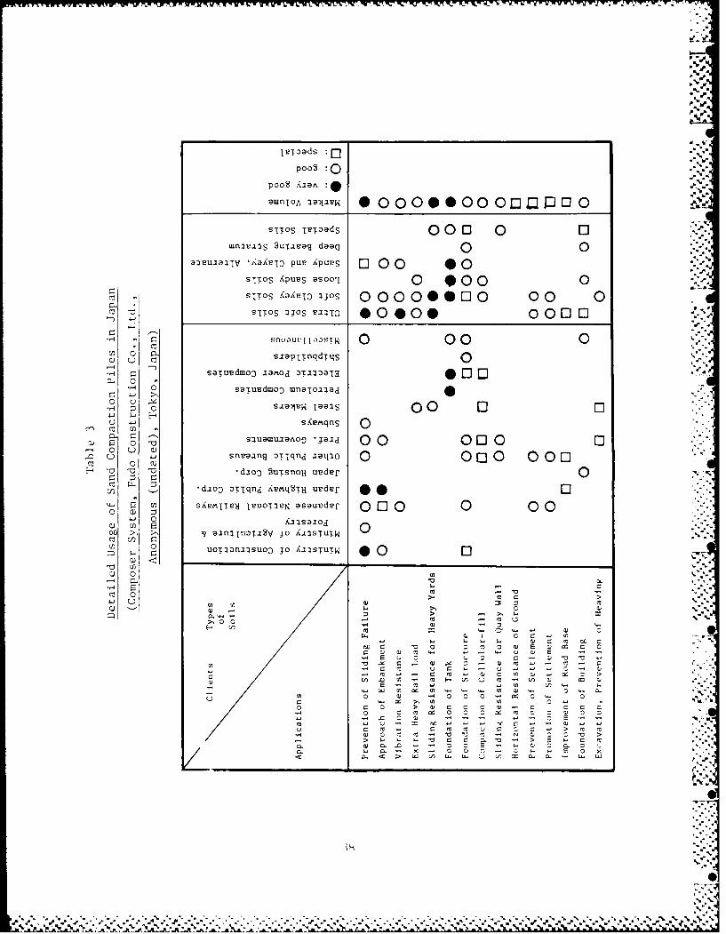
A summary of the detailed usage of sand compaction piles in Japan is given
in Table 3. Fills, embankments, and tanks are routinely placed on very
soft cohesive soils having shear strengths as low as 100 psf; construction
is common on soils with shear strengths from 200 to 300 psf.
5 . In reclaiming large areas of land from the sea, usually a dike is
first constructed around the area to be reclaimed. To prevent a stability
failure, the soft sediment is either dredged out and replaced with %%"
hydraulic fill, or else the dike is placed directly on the soft sediment
after reinforcing it with closely spaced, mammoth compaction piles as
shown in Figure 16. Mammoth compaction piles have the following advantages
over conventional dedging and hydraulic replacement:
t in ilr , nr cd i s I , re iSt i atnt i I I %- reimovod using the malmmotha &II), t I on 1) i I es mr n thd d isposal ot waIste sed iment is not necessarv
.1 i i, it iO I s atrt, (I i.pohl is hig:hl dc,.sirah It e in Japan from themy ri-,' t ; I v is'wpo ilnt heOa' sr Of thin high pp1t ation d ns i t ...
A dI n -, ml ('In o.t, aintI i'sing thr manmo h rollpaet iolli 'I t dI til ill I 'I dulpcd ri I' IIi (' ti i Il
, .%
I 'h; ,L. r t I :5i.1d p i i , s ,,ust r uk L d h v th le 1u. ooth 'ompa tim t i-ol-
p lk, 7I thIs t 11011 r-.uu i :i um i n IIIuII : euin t Of tI'AI..ran eC( outs ide the-CI 11,* I u t lrust iII. in I -;Iras t Crtd in1 n. '.- s it.,trI s thin-
1., V' , - . It Ciar slpts0 in the .-so t Ot 'giln .otdinu nt.s tqnir-Out It I- Ii Ia snt It th ~n t Ikt in am1 a I.
.. ~ ~ [t, I:.:::.,~ ,.xI t tI 11 hL'*" :It~ I~ S .t I d t l C C 11 ! t t,
1' - t i I I t I I 1 s .t.
.ammot compact ion pi 1,-i ire frequently used in reclaiming land
frm thoe ,,e in J:apan. ,:,):ivent ional dredging and replacement techniques,
,wtv,11,e," m a y m hye-i wherre en vi ror Iment a or other restrict ions do
nit pre,vent their u'.se. thor -Ippi ;st or of tiiJ :: i) tt,,I l '' I U . ), in Ilk-
t0
IeToads:Q-5
Poo2 :0 .
sTTOS TL'TzdS 0 00 0 0mnei 2uTivag dae 00
aivulalTv '~a~r[j puV Xpus 0C0O 0 0SIlos iPUUS asool 0 9000 0SITOS xav~ IJOS 00000000 00 0
ci 7 sTTOS 3JOS Le:E 0000 0 001 0. 4-J
snoaup I 1,-svrT 0 00 0LsIaPT~nqdTqS 0
Ssaiusdmo:) iaoc D~2O 0 0E0.H saTupdmoo mflaTOalad
:n c SI8aiSN ia~S 00 1-' 0u 4-)sXLSmqnS 00aatao -jai
E 0000.0 C9 - snLeaing DTiqa'qO0~0 q n c -~q o 0 0
_TJ 7; a djoo 2trrsnoH uvder
djoo :VETld AstMq2TH uedur 00F siemULed IuoTts,, asauedef 0 0 0 0 0 0
o w )4-1 0
C O ~ > qann~2 JO X1ISTUTW 0,J) UoTaoli2suoo JO AIISTUTN 0
-CW
mJ 0 >
C, >
4)0 3
U) a SCC
W- V) -n -C) 0 C C, .~
C) 0) 0 3 0x o) C v 3 .- -~ - o C) S
- = .. ' - - -C) -3 0)
I. .> E w M -
C > W ) C w C, L) - D. C C
- C 3 ~ C C ~ C C C C
.C~~~ 0%)- . ~ C E -

.~~~~~(Rcaie Land~I~~1~~~ h . ' k ' . . ~~ . P~~N A. a - p - .
M ICP Piles Sand Drains -1 MCP Piles
Figure 16 . Land rec iama t ioti iis-ing manimot hCompact ion p1iles (MCP)
(a) Bridge Pier (b) Waterfront
(c) impoundment (d) Impouindment
F i urc 1 7. 'ivpiA jht l p ; n irnimu I i pilk Ir it hod
( 'Mallm )HtI (>mivlp) ze r S 5 *in lI( .00- I Col I it ii I. C(. *llf\-
Illo l" ( llid It k l)
%A

General Criteria and Practices
55. Japanese design practices and design criteria for sand compaction
piles for selected organizations are summarized in Table 4. Both square
and triangular grid patterns are commonly used in Japan for all types of
site improvement work. Sand compaction piles constructed on land have area-
replacement ratios varying from 40 to 50 percent while sand piles
constructed in the sea have area-replacements ratios varying from 20 to 90
percent depending on the application and soil strength. A higher
replacement is usually employed for reclamation of land from the sea using
the mammoth compaction piles method than for projects on land; for this type
reclamation the piles often touch each other with typical area-replacement
ratios of 70 to 80 percent. Finished sand compaction pile diameters generally
vary between 2.4 and 32 in., and mammoth compaction pile diameters between
32 and 70 in. A pile spacing (pitch) is used between 4 and 10 ft. Typically,
however, the spacing is between 5 and 7 ft. If a small sand compaction pile
spacing is used, problems may be encountered in previously constructed
adji acent piles, and special precautions must he taken.
56. Sand compaction piles become hard to install in soils having
standard penetration resistances greater than about 15 to 20. To penetrate
very dense sand layers and hard clay seams water jets having pressures from
70 to 1, 200 psi are somet ims placed on the sides of the casing (Hayashi ,
1981). Japanese engineers apparently prefer to carry sand compaction piles
down to a bearing strata. This practice is in agreement with stone column
design practice in the United States and Europe. However, when the bearing
stratum is quite deep, a floating sand pile design is apparently used in
Japan in some instances for stability applications (Mizutani, 1981).
Stability Considerations
Stability performance
57. The fact is well established in Japan that. sand compaction piles,
n;'ltII 1,:, )l tin p i I , , d rt r n t ( Ind p1 ] s I 11,AVk ;I r(c Ord o0 1 ,tIod per-
ti,, i~L.tt with r&'spt'.t ti stai i it\'. All ol tie Ja;pani se in ni trs i ntvr--,..,,,i ",t, 1>it 'l <u t t t 1 y i I i t o tI< t I I , 11) A' M 'il t'l ~ L' t) l' t 1100 S 11L ' I ,
I i 1,":-d p'i i t t~ , l rII ,t t 1. 1t<, 11 1 I M ,).n t lto st 11) t I t't v II ti b i I tv l I I( t , s,-,
400
%404O ::iS

- - - - o - - - .. - .- . -.
- -.. ;-- t ..
ii "..'
0.,
C-.
C -" -.
j C1 ".'-"8~*0 C C:C ,-
A 8 AC AC CAC £ -0 A'~CC A, i.-

rather remarkable considering the widespread use in Japan of sand compaction
piles for this purpose.
58. Aboshi et al. (1979) have described a well-known trial embankment
constructed on 36 ft of organic silt having a shear strength of 200 to 300
psf. The organic silt was underlain by 95 ft of peat with a shear
strength varying from 150 psf to 250 psf. A test section without sand
compaction piles failed at an embankment height of 21 ft. Another section -'C
of the embankment was constructed using a squere grid of sand compaction
piles at a 6.6-ft spacing resulting in an area-replacement ratio of only
0.1. Nevertheless, failure did not occur under an embankment height of
48 ft. The exceptional performance of this embankment suggests why the
primary use of all types of sand compaction piles in Japan is to prevent
stability failures.
59. The method of stability analysis previously presented has been
found in Japan to give conservative results for embankments constructed on
sites stabilized with sand compaction piles (Aboshi et al., 1979). In 15
test embankments, embankment loads between 1,600 and 7,100 psf were
supported by sand compaction piles having area-replacement ratios between
0.16 and 0.20. Calculated safety factors of these embankments with respect
to a stability failure varied from 0.99 to 1.59 with seven of the
emtankments having safety factors less than 1.10.* Nevertheless, none
of the embankments failed even though over one-half of them were
constructed over soils having shear strengths between 120 and 300 psf.
Angle of internal friction
60. The angle of internal friction s of sand compaction piles used ".-
for stability analyses in Japan appears to vary from 30 to 400 depending
upon the organization (Table 4). Fudo Construction Company, Ltd. routinely
use s = 300 for design although it is admitted that 0 could be as great as
350. Nippon Kokon Co., Ltd., a very large steel company, uses 300 for %
dumped sand and 40° for vibrated sand having an N value of 20 to 25; for
this condition they feel the angle of internal friction may be as large as
45o . Kensetsu Kikai Chosa, a well-known Japanese manufacturer of vibratory
hammers, recommends angles of internal friction between 200 and 450
It is noct chIr it consoJ id'it ioi ()I- thc tlfl(I;lt ion soils J in g & I-t ic-tion was considered in the stability analyses. Undoubtedly long-term Sconsolidation helps to explain the success of these embankments.
42
C W .-

_Ii
depending upon the material; for a coarse clean sand a value of 450 is
recommended. The validity of using angles of internal friction of f40" or
more for design is not recommended by the writer. Such high fri ction ati] I
would require a very small void ratio and coarse, angular particles.
61. For sand compaction pile design in the United States, a
reasonably conservative value of the angle of internal friction should be
employed in stability calculations at least until sufficient experience has
been gained using this technique. For sand compaction piles constructed
using sands with less than 8 percent silt content, the recoinmendation is
made that an angle of internal friction s between 300 and 380 be used
depending upon the effective grain size, gradation, and densifica ti,,n
attained. The angle of internal friction used in design should of course
be no greater than the value of (s estimated from the design relative
density and/or standard penetration resistance obtained from field
measurements and corrected for overburden pressure.
62. The writer recommends a safety factor with respect to a stability
failure of at least 1.3 and preferably 1.5. It is recognized that the
sponsor (CE) ias its own criteria on safety factors for slope st;lhilitv
analvses defined in LM 1110-2-1902 ITS Corps of Engineers, 1970. The at .]
safetv factor selected should depend upon a number of f,-tol-s inc l ud inl,
(a) the specific problem inc I ud ing s ite cnditions and type const ruct i ,n,
(b) whether an increase in shear strength due to consolidation has bcn
considered, and (c) existing criteria of the dcsign aigenc'. In lipian a
safety factor of 1.2 to 1.3 is commonlv ,SCd for stabilitv appi it ion,.
Local bearing failure
63. Sand compaction piles, when used for stability applications,
carry reasonably large shear forces (but not as large as stone columns).
These shear forces could conceivably result in the sand compaction pile
punching into the surrounding very soft soil although this type failure has
not been reported in Japan. A local bearing (punching) type failure was
observed in the I:S ;it Imirdan Roa-d 'trmina l durini a dircct shlr test ,;I
a stone column (Barksdale and Bachus, 1983a). Stone columns in general
would be more susceptible to a local bearing type failure than sand
compaction piles since they are usually designed to carry higher axial and
hence shear loads (i.e., stone columns are usually designed using a greater
angle of internal friction). Nevertheless, the posibility of a Local
43
%- 1 4

bearing failure does exist for sand compaction piles ,natructel ir-
extremely soft sediments having undrained shear, strength less t -ir; rnj,
250 psf. A discussion of local bearing failure, together h ,
presentat ion of design theory and design charts has her. gven Ijo:enwr -
(Barksdale and Bachus, 1983b).
Stress Concentration
64. The value of the stress concent rat ion factor" r ,,3s "la:; m'irl
important effect on both stability and settlement calculat irm. F )r t t
embankment at Fukuyama the measured stress concentrat ion facto,4:t.w
almost constant with depth, increased from 1 to about 4 as tri5 1 i-tt -!,i
embankment was placed (Aboshi et al., 1979). After the ernhanment wa3.%'
completed the stress concentration factor continiued to :ncrea3se up to ibout-
5 as consolidation occurred. 'urt her, the average stress concent rat ion
factor n measured at twenty sand compaction pile sites in Japan underlain
by soft clay is 4.9, with observed values for the twenty sites varying from
2.5 to 8..A An n value of 4 was found to give the best agreement qith
the measured time rate of settlement curve for one tes embankment.
65. In estimating the magnitude of stress concentration the reader
should remember that theory shows n to increase for ( ) increasing vilues
of the modulus ratio of the sand column to the in situ soil ani lt for"
decreasing area replacement rat ios )gawa and ishi, 9Ib). For de,3 i gn
Fudo Construct ion Co., Ltd. uses a stress concentrat ion factor n of .0.
Nippon Kokan Co., Ltd. uses n 3.0 for, dumped sand and n 10.0 for
vibrated sands having an N value between 20 and 2L Kensetsu Kikai ,,hosa i'1recommends an n value between 4 and 5. For the present time a stress •
concentration factor n of 2 (certainly no more than J) i a rtcommended for,
stability applications )f sand compact iion piles construted in t:-he 1!nited NStates. For settlement calculations a value of' n between anl issuggested. I
HIit, itret-is ( cl onttri ti oll I< -
, I it I-li ,, V 1. 1
measured.
.- 4 .4

Sand Pile Gradation
66. Sand is usually used in Japan for site improvement work since It
is the most readily available material. Gravel and even crushed stone
have, however, been used on a limited basis in Japan and Taiwan. For site
III p rov eflt' It uInIIIg' s'lnd c(u)IIIp.I t it) 111 i I es , t lII e st I e t ion ,I ;I prptr Sd.iII dr
gradation appears to be even more important than for the much larger size
aggregate used in stone columns. The important beneficial effect of
increasing sand size on standard penetration resistance after densification
is illustrated in Figure 18.
h7. Saito (1977) has presented extensive field data showing the
import ant detrimental effect that f ill 'S havt t .s ,ind-; i mprove'd usin the
vibro-rod technique (Figure 19). The vibro-rod method is used to densify
sands following a procedure somewhat similar to the Terra Probe (Brown and
Glenn, 1976). The vibro-rod consists of a closed pipe having a number of
outward protrusions that is driven by a vertical vibrator located at the
top of the pipe. Saito found as the fines content of the sand increases up
to About 15 percent, the standard penetration resistance after construction
decreases exponentially. Above about 15 percent fines, vibration was found
to have little beneficial effect on the standard penetration resistance of
the :soil. These findings clearly indicate that specifications for sand
compaction piles should require a clean sand with very little, if any,
f i nes.
6. Sand gradat ion specifications from five Japanese government
ltb irwr ,i[n i,, It, t ,ivcn inl Fiigur. t . IFigur a 21 shows aIctu l s,lnd
gradations use to construct mammoth compaction piles over water at
four land reclamation sites. All of the sand specifications called for
well graded, fine to medium sands which do not have minus 0.05 mm sizes.
Somewhat lower quality sands are apparently also sometimes used which have
less than 10 percent fines, and grain sizes varying from 0.00014 to 0.04 in.
as indi e;ited in I i,,r,
Quality Control
bO. Specifications in Japan for sand compaction pile construct ion
usually require a minimum standard penetration reai: taricc of oither the
454 5 .'%.'
A S ~ hP', ,

N.
S00 F(,A1IRA
2. In PI Ii.0 ~ ~1 ni 111(1i 0
0 m pdil*
0 %0
o0 P0 4,
20 ___
0@ ,
10 e-
100
0 5.-Z
0 .10.2
Pf fe, t ive fr.lin D I
Figure 18. Influence ot graiin size- on standairdpenetration resistance after denis if iclatitn-st rong sa-nd pi I c met hod (''SVS Method 'I.-Cl)i r IaIn format ion , Kense tsn K ika i Chiosa; Co. , L.td.
Osaika, Jaipan)
0P
300
Al I\ I ' mr.mn
300
AL.
0l. if N EI I 0 t i ,' I i _
-o-

0. 5 2
Silt Fine Sand 'ledium Sand Coarse
0
,.0 Io 50 ,1/
,)1 0.5 .1 .5 [.0 10 5
G rain Diameter Imm)
Fi gure 20. Sand gradation specifications used by fiVh a rbor agenc ies
7' b0 Practical Limits---.0 #-/
f14
FPractical Limits
r14]
200
0.5 1 5 10 50
Grain Diameter, mm
Sr-. 'I . .Sind gr'd it ions used for fouir imammo)th compact ion
i ,. 1, > ( >I .i lt h ( ,m p o z t-r S v s t e m s ," l'u d o C on s t r jle t o -n
Co., .td. , i'okvo, ipan)
4.i47
oi
. .'- > - .. .. : -- .. : - -.: : . - %. v,..--....-..'....'...-..-...-..v...,..-..-.-..v.-..-.,-,..--.-.......--..v-.-.."..*.

%
sand pile or the in Situ soil at sites underla in by cehesiniless le
materials. For sand compaction piles constructed in cohesive soils the
penetration resistance is usually measured down the center of the pile.
Specifications usually require a standard penetration resistance N value
between 10 and 20.* At sites underlain by sands, the penetration
resistance between compaction piles is usually required to be greater than
10 to 15. As shown in Figure 22, an average N value of 18.9 was observed
for a large number of mammoth compaction pile jobs with the standard
deviation being 5.4.
70. An indication of the current practices in Japan of specifying
sand pile construction work can perhaps be best obtained by briefly
describing the practices followed at the four sites visited. For the
construction of two LNG tanks at separate sites underlain by sand,
specifications required N to be greater than 15 at the center of the sand
compaction pile grid; one site used a square grid and the other a
triangular grid. At a waste disposal station site being reclaimed from the
s(1', thre heborings were put down in every third mammoth compaction pile;
originallv one boring was to be placed in each pile. The specifications oil
this job required a standard penetration resistance greater than 15 in the
center of each pile. At a land reclamation site for apartment houses , 3 or
-4 test borings were to be made for a total of 1,584 piles. Specific at ions
re(quired N to( he greater than 10. Typical values of N measured ;it this sitewere t it i d1cpth of 10 ft, 20 ft at 39 ft, and 30 at 75 ft. As expected, d
the niimber of piles tested varies considerably depending upon the specific
application and designer. As a general rule-of-thumb Fudo Construction
Co., Ltd. usually tests one pile for every 3,280 lin ft of pile
constructed. .
71. In developing specifications for sand pile construction work, the
effect of overburden pressure should be considered in developing required
values of the penetration resistance in the field. At the present time it
is apparently more usual in Japan to not consider the effect of overburden S
pressure for quality control, although many Japane engineers recogni'o-
this need and undoubtedly some correct for overburdlen pre,re. --,.
~, .-A * p rI'ut Il v t[ sp cifl v 3 V1lII is u-;iil'. I ! -,t t ' ' di, 0
4 8
-

SCa
- = 18.9 avg.40 2=5.4
cuMC P LQ 30
20
10
0 1C3
SPT at Center of Pile (N)
Fi gur .22 Observed variation in SPT valtI fora large number of mammoth compaction pile("Mammoth Compozer System," Fudo Construction
Co., Ltd., Tokyo, Japan)
-':4 ~ 0.25
Cone Indexg" " 'Z Before "-
' Before
aShear 0.05r- Strengtho Af ter
0 00 2 4 6 8 10 12 14-"
Time in Months
Fi gurt, 2 1. I:1 I-l c t of )d i Il const ructim il on shear .st runth as ,I IncL 01 on r t imt (after I chi moto,
1980)
%

Influence of Lateral Pressure on SPT Value
72. Construction of sand compaction niles typically results in
standard penetration resistances increasing by a factor of 2 to 5 as shown
in Figure 13 and 14. Based on extensive field measurements made at the
Ogishima Island Steel Plant, Saito (1977) has concluded that the large
measured increase in standard penetration resistance is not accompanied by
a corresponding large increase in relative density. As a result, the
relative density obtained when the measured N value is corrected for
overburden pressure was found to considerably over-estimate the actual
relative density of the improved soil at the Ogishima site. The
misleadingly large standard penetration resistances measured after site
improvement is attributed to the significant increase of lateral pressure
during densification of the sand. Pressuremeter measurements indicated an-
increase in K. from about 1 to as much as 6. The important effect of
lateral stress on standard penetration resistance has been previously
reported (Rodenhauser, 1974; Zolkof and Wiseman, 1965; Schmertmann, 1975).
More research is certainly needed to develop techniques for handling the
effect of lateral pressure increase on relative density.
Strength Loss Due to Sand Pile Installation .\, "
73. Construction of sand compaction piles in cohesive soils causes a
significant loss of strength due to remolding of the soil surrounding the
pile (Figure 23). As pore pressures dissipate the shear strength of the
clay gradually increases, with the time required to regain its initial
strength depending to a great extent upon the physical-chemical
characteristics of the soil. Field measurements in Japan indicate that
typically from 2 to 20 weeks are required to regain initial strength with 2
to 3 weeks perhaps being more usual (Ichimoto, 1980; Aboshi et al., 1979).
For mammoth compaction piles the effect of remolding is even more severe ,
than for" sand compaction piles, but strength gain has still been observed
(Ichimoto, 1980).
74. Ichimoto (1980) recommends waiting in cohesive soils at least a
month before loading sand compaction piles to allow at least a partial
. .. . .. . -
6)
-0

recovery of initial strength. Further, when constructing sand compaction
piles in granular soils, the existance of a clay seam or even a relatively
impervious fine sand seam will prevent the N-value from increasing until
some time after construction. Therefore, if low permeability layers are
present the standard penetration resistance should not be measured until as
long as possible after construction (Ichimoto, 1980).
75. In constructing sand compaction piles in very soft clays, loss of
strength due to remolding can be an important problem. To overcome this
problem, sand having a high angle of internal friction should be used or
else the construction should be organized in stages (Ichimoto, 1980). For
stage construction, first place the piles at twice the final spacing and
later, after strength gain has occurred, install a second series of piles
midway between the piles previously constructed.
76. Sand compaction piles are vibrated into the ground. As a result
important shear stresses are transferred to the surrounding soil. Also
"smear" of the native soil occurs adjacent to the sides of a sand
compaction pile. Field studies show that when a pipe is pushed into the
ground without I ttv;ng,, i g si tnit i ',nt rcd ti i in IitL'ral perim;ihi it'
occurs; the effuct of smear is much 1ccs; 1uwvCv'r, when the pipe is jetted
into the ground (Barksdale and Bachus, 198'3(a); Cas:t tr nde, and I'uI , 196 ).-"
S ince stone columns are usually jetted into the ground, smear effects and
tne remolding of the surrounding soil is much less than in sand compaction
pil, construct ion.
SL
--S.
0
, -
- %. . "......

PART V: SUMMARY AND CONCLUSIONS
77. The primary use of sand compaction piles in Japan is to prevent
stability failures. When settlement is of concern, preloading is often
used after the sand compaction piles have been constructed. Sand "
compaction piles are used extensively in Japan to support dikes,
embankments for roads and railways, stockpiles of heavy materials and tanks.
Embankments are routinely successfully constructed on cohesive soils with
shear strengths varying from 200 to 300 psf that have been reinforced with
sand compaction piles.
78. Sand compaction piles are constructed by driving a steel casing
(pipe) filled with sand to the desired elevation using a heavy vertical
vibrator placed at the top of the pile. The casing is then gradually
extracted using a stroking motion to densify the sand. Using this
construction sequence, soft cohesive soils surrounding the pile are not
left partially unsupported as is usually the case during the construction
of stone columns. Also sand compaction piles are constructed by dumping
sand down the casing and not down an uncased hole as occurs during stone
column construction. Since jetting is not normally used, construction of
sand compaction piles does not result in a large quantity of excess muddy
water which is often environmentally objectionable in stone column
construction. Erosion of fines in'o the sand compaction pile should not be
a problem for normally used gradations of sand. Finally, construction of
sand compaction piles, which is fast and efficient, utilizes low-cost,
often locally available sand.
79. The important disadvantages of using sand compaction piles to
prevent stability failures of embankments appears to be (a) sand has a
lower angle of internal friction than the large size stone used in stone '
columns and hence requires a larger area replacement ratio, (h) smear and
remolding effects are greater for sand compaction piles than stone columns
and, (3) contractors in the United States do not have either the experience
or mechanized equipment for rapidly constructing sand compaction piles. -. -1
Finally, sand piles would not act as vertical drains during an earthquake.
For many applications these disadvantages are not serious. Several
different vertical vibrators are presently available in the United States
that could be used to construct sand compaction piles. The automatic skip
52
%0

loading system used in Japan and Taiwan could be imported from Japan, or
else a similar system (or even a simple version) could be designed and
constructed in the United States.
80. Typically approximately 80 percent of the consolidation
settlement occurs in a cohesive soil reinforced with sand compaction piles
within about 8 months from the beginning of construction. Therefore, an
important part of the settlement due to an embankment should be complete by
or shortly after the end of construction; consolidation of stone column
improved ground should progress somewhat faster. Because of the lower cost
of sand and faster production rates, sand compaction piles constructed in
the United States using efficient equipment similar to that employed in
Jdpan should cost about 1/2 to 2/3 the cost of stone columns. For many
applications involving, for example, stability of embankments, sand
compaction piles offer a quite viable alternative to stone columns.
Therefore on appropriate projects alternate bids and/or demonstration type
projects should be used to encourage the development of sand compaction
pile technology in the United States.

- - .. . . . .. . . .- -
REFERENCES
Aboshi, I., et a1. 1979. "The Compozer - A Method to Improve Characteri st icsof Soft Clay by Inclusion of Large Diameter Sand Column," Proceedings,International Conference on Soil Reinforcement, Reinforced Earth and OtherTChliques, Vol. 1, Paris, p. 211-216. VBalam, N. P. , and Booker, .. R. 1979. "Analysis of Rigid Rafts Support'd 040by (;ranular Piles," The Universitv of Sydney, Report 339, School of CivilElngineering, January.
Barksdale, R. D., and Bachus, R. C. 1 983a. "Iesign and Construction of .
Stone Column," Vol. I, Federal tHighwav Administration, Report FIIWA/R-83/026,210 p., December.
1983b. "Design and Construction of Stone Columns," D ra ftReport, Federal Highway Administration, February.
Brown, R. E., and Glenn, A. J . 1976. "Vibroflotation and Terra-ProbeComparison," (;eotechn ica 1 Journal, ASCE, Vol. 102, No. GT10, October.
Casagrande, L. and Poulos, S. 1968. "On the Effectiveness of Sand Dra ins,"Canadian Geotechnical Journal, Vol. 6, pp 287-326.
Delapierre, J., Van Den Poel, J., and Wallays, M. 1980. Amel ioration.Mechanique En Profondeur Des Sols Meuhanische Die ptev erdichting,Pieux Franki - Liege.
Hayashi, K. 1981. Personal communication with Mr. K. Hayashi, ManagingDirector, Kensetsu Kikai Chosa Co., Ltd., Osaka, Japan, March.
Holtz, W. G., and Gibbs, t. J. 1957. "Research on Determining Densit v ofSands by the Split Spoon Penetration Test," Proceedings, 4th InternationalConference on Soil Mechanics and Foundation Engineering.
Ichimott, A. 1980. "Construction and Design of Sand Compaction Piles," SoilImprovement (;eneral Civil Engineering Laboratory, Vol. 5, .une, (in Japanese). p.r
1Idd, C. C.,and Foott, R. 1977. "Foundation Design of Embankments Con- 0struicted in Varved Clays," FHWA TS-77-214, Federal Highway Administration, May.
Liona rds , (;. A. (Ed it or) . 1962. Foundat ion__Engineering, 1st Ed. , McGraw-Hill, Inc., New York.
>izntan i, Y. 1981. Personal Communication with Mr. Y. Mizutani, Presidio1t,K('ns''tsn Kika i Chos; Co. , Ltd. , Osaka, Japan, March.
Ow, Iw;l, M., aInd lshido, 1. 1965. "The Vibro Compozer Method ;as App] ie'd to(',pct ionI o SInd I~inodation Soils,'" Soil and Foundation, Vol 11, No. 2, (in
tP din.nsi ,, .1. 1974. The E ffect of Mean Normal Stress on the Bl w t>nn1 t t
lt'. "II'i il hos (Jiatt:ihoi'cit' Sind," iuke Iniversitv, Pro<ect Rtport
s it,, .. 1197/. "'haraicteristics of Penetration Resistance of a l-,clajime-d'+,i ad x I ps it .d Tin ir I fh inge 'lhtroU'h Vibratory Compact ion," Sol 1s anfdhmnodit ins1, Vl. 17, No. ', December, p. 31-43.
/34
_0,

r:,nr.n ' 'v -, w' ' r r, rrtv,,. tr ... ., pr . ....rq ~r ~; ;w .r,zyJ. Vf 'r 7 L : i . .
Schmertmann, J. H. 1975. "The Measurement of Insitu Shear Strength -
State-of-the-Art Presentation to Session 3," Proceedings, ASCE SpecialtyConference on Insitu Measurements of Soil Properties, Raleigh, Vol 11,pp. 57-138.
Tanimoto, Kiichi. 1973. "Introduction to the Sand Compaction Pile Method asApplied to Stabilization of Soft Foundation Grounds," Division of AppliedGeomechanics, GSIRO, Technical Report No. 16, Australia.
US Army Corps of Engineers. 1970. "Engineering and Design Stability of Earth
and Rock-Fill Dams," Department of the Army Engineer Manual EM 1110-2-1902.
Zolkof, E., and Wiseman, C. 1965. "Engineering Properties of Dune and BeachSands and the Influence of Stress History," Proceedings, 6th InternationalConference on Soil Mechanics and Foundation Engineering.
,.

I?-
Df 'D


![][MHhH[DHÇ } ~ , /Ç.k;kHÇ](https://img.dokumen.tips/doc/110x75/6159b498befa93525c106069/mhhhdh-kkh.jpg)