Embed Size (px)
Citation preview

Image Resampling
ASTR 3010
Lecture 21
Textbook 9.4

from Tom McGlynn’s IPAM Workshop presentation
Why do we need to resample?• Display – transform image into ‘standard’ formo Undo warps and distortionso Transform to standard frameo Resizing: upsampling or downsamplingo Rotation
• Image comparison – transform one image to match another
• Mosaickingo Building sky region and all sky images
• Image arithmetico Dither additions, image differencing, speckle analysis

Resampling example
SkyView transforms the EGRET all sky map in Galactic coordinates to Equatorial coordinates.

Nearest NeighborNearest neighbor assignment is the resampling technique of choice for discrete data since it does not alter the value of the input cells.
However, astrometric accuracy is degraded.
gray grid: input gridorange: nearest neighbor in the inputred: output value

Bilinear interpolation
Bilinear interpolation is done by identifying the four nearest cell centers on the input raster (in orange) and assigning itself to the weighted average of the four values. This process is repeated for each cell in the output raster.

Bilinear interpolation
• A common method for resampling images
ab

Cubic interpolation
by identifying the 16 nearest cell centers on the input raster (in orange) and assigning itself to the weighted average of the 16 values.
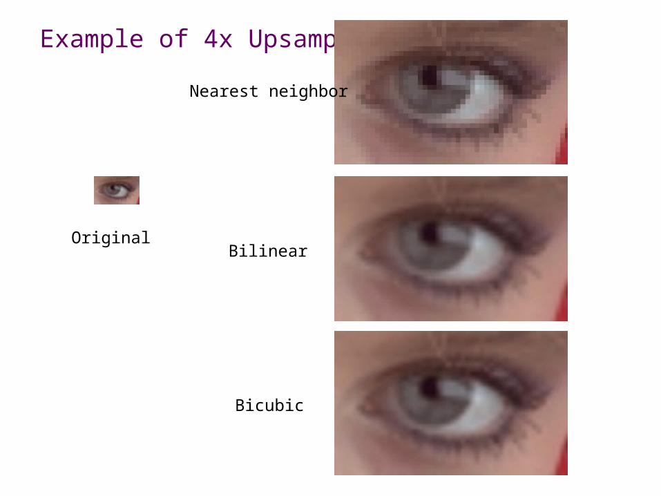
Example of 4x Upsampling
Nearest neighbor
Bilinear
Bicubic
Original

Interpolation smoothes out features
0.5 pixel shiftedandLinear interpolated
resampled x3shiftedand interpolated
Original Signal

Resolution enhancement (or Super-Resolution)
• Nearest Neighbor degrades positional information• Bilinear (or other low order interpolations) smooth the signal
• Three commonly used resampling strategieso Shift-and-add (and interpolate)o Interlaceo Drizzle

Shift-and-add
output grid input grid

Shift-and-add
output grid fractional contribution from aninput pixel to several outputpixels

Shift-and-add
output grid fractional contribution from aninput pixel to several outputpixels
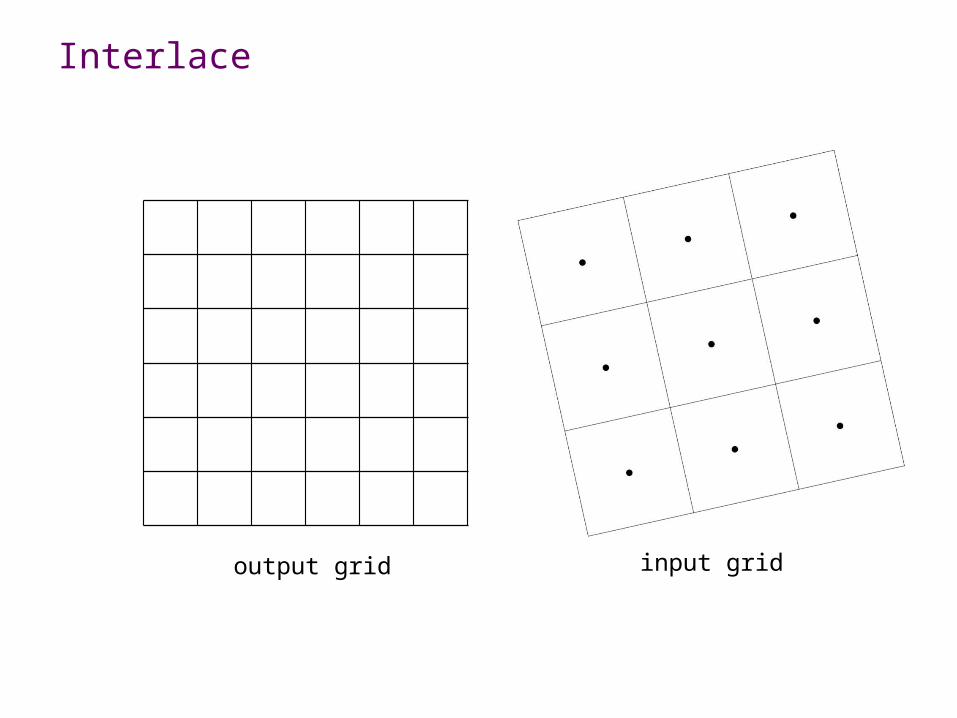
Interlace
output grid input grid

Interlace
Repeat this process for many input images with known dithers super-resolution
examine each input pixel. locate its transformed center in the output grid. assign ALL input pixel count to a corresponding output pixel (no fractional coordinates)

Interlace 1D example: Python HW#5
• Four samplings of a double Gaussian-peak distribution. • Each sampling was shifted (“dithered”) with +0.25
pixels to the right.
sample1=[0.39,38.92,26.39,34.27]sample2=[3.39,42.92,38.20,15.50]sample3=[12.02,36.63,46.63,4.72]sample4=[26.32,27.30,45.54,0.80]
• Construct an interlaced distribution showing a 4 times better resolution.

Problems and Limitation
• Interlace for a single image is a flawed approach: o it creates a discontinuous imageo positional error b/c we ignore any fractional coordinateswith many input images, these two problems will become less significant.
• Shift-and-add and Interlace methods both require precise information on “shift” between images
• Limited precision of many actual telescope controls usually produces a set of images whose grids are randomly dithered at the sub-pixel level not suitable for S&A and interlace.

Drizzle (variable-pixel linear reconstruction)
output grid input grid
input drop

Drizzle
output grid input grid
empty output pixel
In Pyraf, pydrizzle is available by “import pydrizzle”
p
d
f=d/p
f0 interlacef1 shift and add

Drizzle Example
• M57• left (original image) right (2x drizzle with 100 input images)

In summary…
Important Concepts• Resampling o shift-and-addo interlaceo drizzle
Important Terms
Chapter/sections covered in this lecture : 9.4