Embed Size (px)
Citation preview
DOCUMENTATIONDOCUMENTATION
SIMATIC VS120
simatic sensors
Image Processing SystemsSIMATIC VS120
Operating Instructions (Compact) Edition 02/2006

Operating instructions (compact)
1
SIMATIC Sensors
Image processing systemsVision Sensor SIMATIC VS120
Operating Instructions (Compact)
Edition 02/2006 A5E00757513-01
Safety Guidelines This manual contains notices you have to observe in order to ensure your personal safety, as well as to prevent damage to property. The notices referring to your personal safety are highlighted in the manual by a safety alert symbol, notices referring only to property damage have no safety alert symbol. These notices shown below are graded according to the degree of danger.
Danger
indicates that death or severe personal injury will result if proper precautions are not taken.
Warning
indicates that death or severe personal injury may result if proper precautions are not taken.
Caution
with a safety alert symbol, indicates that minor personal injury can result if proper precautions are not taken.
Caution
without a safety alert symbol, indicates that property damage can result if proper precautions are not taken.
Notice
indicates that an unintended result or situation can occur if the corresponding information is not taken into account.
If more than one degree of danger is present, the warning notice representing the highest degree of danger will be used. A notice warning of injury to persons with a safety alert symbol may also include a warning relating to property damage.
Qualified Personnel The device/system may only be set up and used in conjunction with this documentation. Commissioning and operation of a device/system may only be performed by qualified personnel. Within the context of the safety notes in this documentation qualified persons are defined as persons who are authorized to commission, ground and label devices, systems and circuits in accordance with established safety practices and standards.
Prescribed Usage Note the following:
Warning
This device may only be used for the applications described in the catalog or the technical description and only in connection with devices or components from other manufacturers which have been approved or recommended by Siemens. Correct, reliable operation of the product requires proper transport, storage, positioning and assembly as well as careful operation and maintenance.
Trademarks All names identified by ® are registered trademarks of the Siemens AG. The remaining trademarks in this publication may be trademarks whose use by third parties for their own purposes could violate the rights of the owner.
Disclaimer of Liability We have reviewed the contents of this publication to ensure consistency with the hardware and software described. Since variance cannot be precluded entirely, we cannot guarantee full consistency. However, the information in this publication is reviewed regularly and any necessary corrections are included in subsequent editions.
Siemens AG Automation and Drives Postfach 48 48 90437 NÜRNBERG GERMANY
Order No.: A5E00757513-01 Edition 02/2006
Copyright © Siemens AG 2006. Technical data subject to change
Vision Sensor SIMATIC VS120 Operating Instructions (Compact), Edition 02/2006, A5E00757513-01 iii
Table of contents 1 Operating instructions (compact) ............................................................................................................ 1-1
1.1 Introduction ................................................................................................................................ 1-1 1.2 Safety Information...................................................................................................................... 1-1 1.3 Hardware and software requirements........................................................................................ 1-2 1.4 Design of the SIMATIC VS120 processing unit ......................................................................... 1-3 1.5 Design of the sensor head with LED ring light........................................................................... 1-5 1.6 Installing the SIMATIC VS120 processing unit .......................................................................... 1-5 1.7 Installing the sensor head with LED ring light............................................................................ 1-6 1.8 Connection of hardware components ........................................................................................ 1-9 1.9 Establishing a direct connection between PC / PG and processing unit ................................. 1-11 1.10 Starting setup support via the Internet Explorer ...................................................................... 1-13 1.11 Sensor Adjustment................................................................................................................... 1-14 1.12 Training a model ...................................................................................................................... 1-15 1.13 Evaluating the object................................................................................................................ 1-18 1.14 Dimension drawing of the SIMATIC VS120 processing unit ................................................... 1-19 1.15 Dimension drawing of the sensor head ................................................................................... 1-20 1.16 Dimension drawing of the LED ring flash................................................................................. 1-21 1.17 Documentation on the SIMATIC VS120 .................................................................................. 1-22 1.18 A&D Mall / Interactive Catalog (CA01) .................................................................................... 1-22 1.19 Service and support ................................................................................................................. 1-23

Vision Sensor SIMATIC VS120 Operating Instructions (Compact), Edition 02/2006, A5E00757513-01 1-1
Operating instructions (compact) 11.1 Introduction
This documentation guides you step by step and will help you to commission the SIMATIC VS120 image processing system quickly. The essential steps for initial commissioning module are as follows: 1. Installation 2. Connecting 3. Adjustment 4. Training 5. Run
1.2 Safety Information The SIMATIC VS120 products comply with the relevant safety regulations according to: • IEC • VDE • EN If you have questions about the validity or legality of the installation in the planned environment, please contact your service representative.
Caution Alterations to the SIMATIC VS120 products are not permitted. Unauthorized opening of and improper repairs to the device may result in substantial damage to equipment or endanger the user. If you install or exchange system expansions and damage your device, the warranty becomes void.
Operating instructions (compact) 1.3 Hardware and software requirements
Vision Sensor SIMATIC VS120 1-2 Operating Instructions (Compact), Edition 02/2006, A5E00757513-01
1.3 Hardware and software requirements When commissioning the Vision Sensor system SIMATIC VS120 the first time, you require the following hardware and software components:
Hardware • SIMATIC VS120 processing unit • Sensor head with CCD sensor chip for detection of the object • LED ring flash for SIMATIC VS with degree of protection IP65 (not included in every full
package), for optimum illumination of the object • Cables:
– Power supply cable – Lighting cable – Sensor cable – DI / DO cable
• Documentation package – Operating instructions (compact) – Documentation CD
You also require the following: • 24 V DC, 2 A power supply; (20.4...28.8 V DC, safety extra low voltage, SELV). • PC / PG with the following configuration:
– At least 500 MHz clock frequency – Graphics card with at least 65536 colors and a resolution of at least 1024 x 768 pixels – Ethernet port with up to 100 Mbps (protocol: TCP/IP)
• Crossover RJ-45 Ethernet cable for connecting the processing unit and the PC / PG
Software • Microsoft Windows XP Professional SP1 operating system with Internet Explorer 6.0 as of
SP1 • Microsoft Java VM or Sun Java VM version J2SE 1.4.2_06 or J2SE 5.0 (you will find
more detailed information on the Internet at the following address http://java.sun.com/j2se/)
Operating instructions (compact) 1.4 Design of the SIMATIC VS120 processing unit
Vision Sensor SIMATIC VS120 Operating Instructions (Compact), Edition 02/2006, A5E00757513-01 1-3
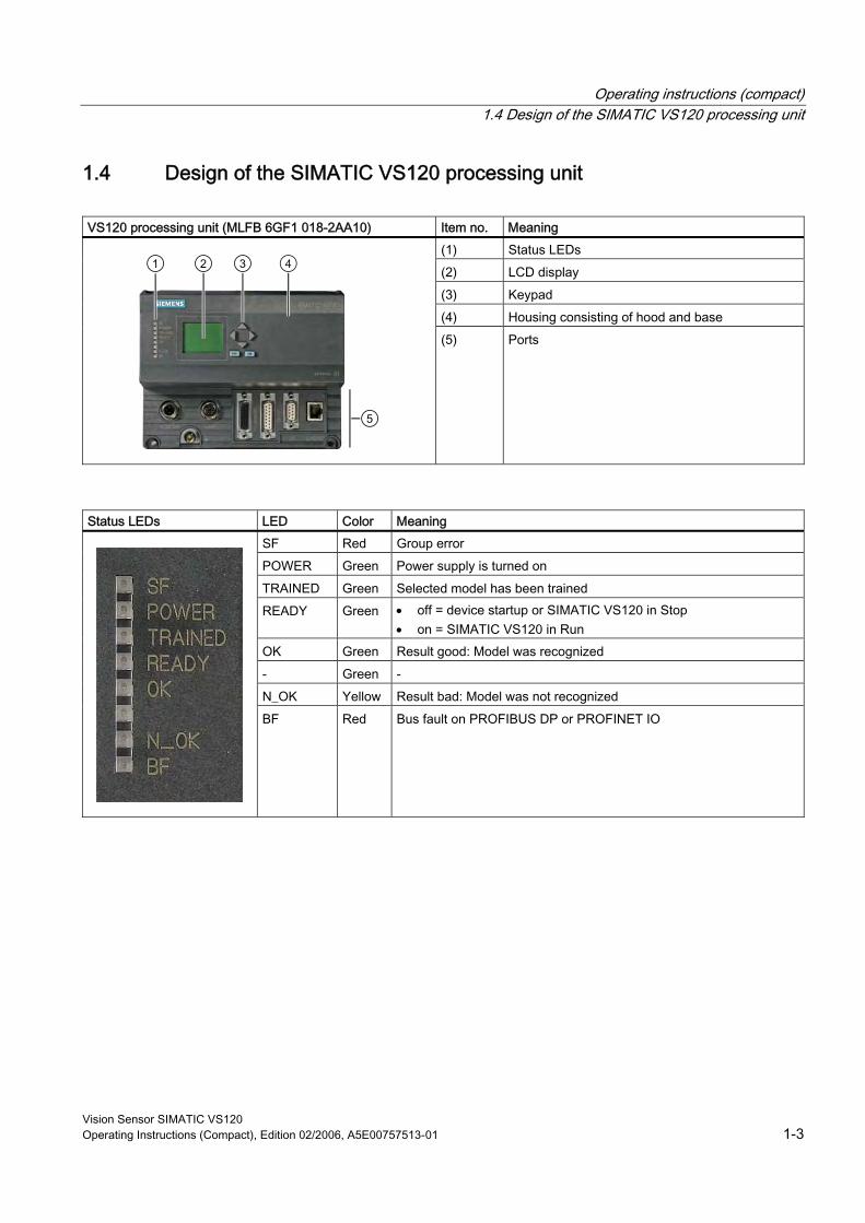
1.4 Design of the SIMATIC VS120 processing unit VS120 processing unit (MLFB 6GF1 018-2AA10) Item no. Meaning
(1) Status LEDs (2) LCD display (3) Keypad (4) Housing consisting of hood and base
(5) Ports
Status LEDs LED Color Meaning
SF Red Group error POWER Green Power supply is turned on TRAINED Green Selected model has been trained READY Green • off = device startup or SIMATIC VS120 in Stop
• on = SIMATIC VS120 in Run OK Green Result good: Model was recognized - Green - N_OK Yellow Result bad: Model was not recognized
BF Red Bus fault on PROFIBUS DP or PROFINET IO
Operating instructions (compact) 1.4 Design of the SIMATIC VS120 processing unit
Vision Sensor SIMATIC VS120 1-4 Operating Instructions (Compact), Edition 02/2006, A5E00757513-01
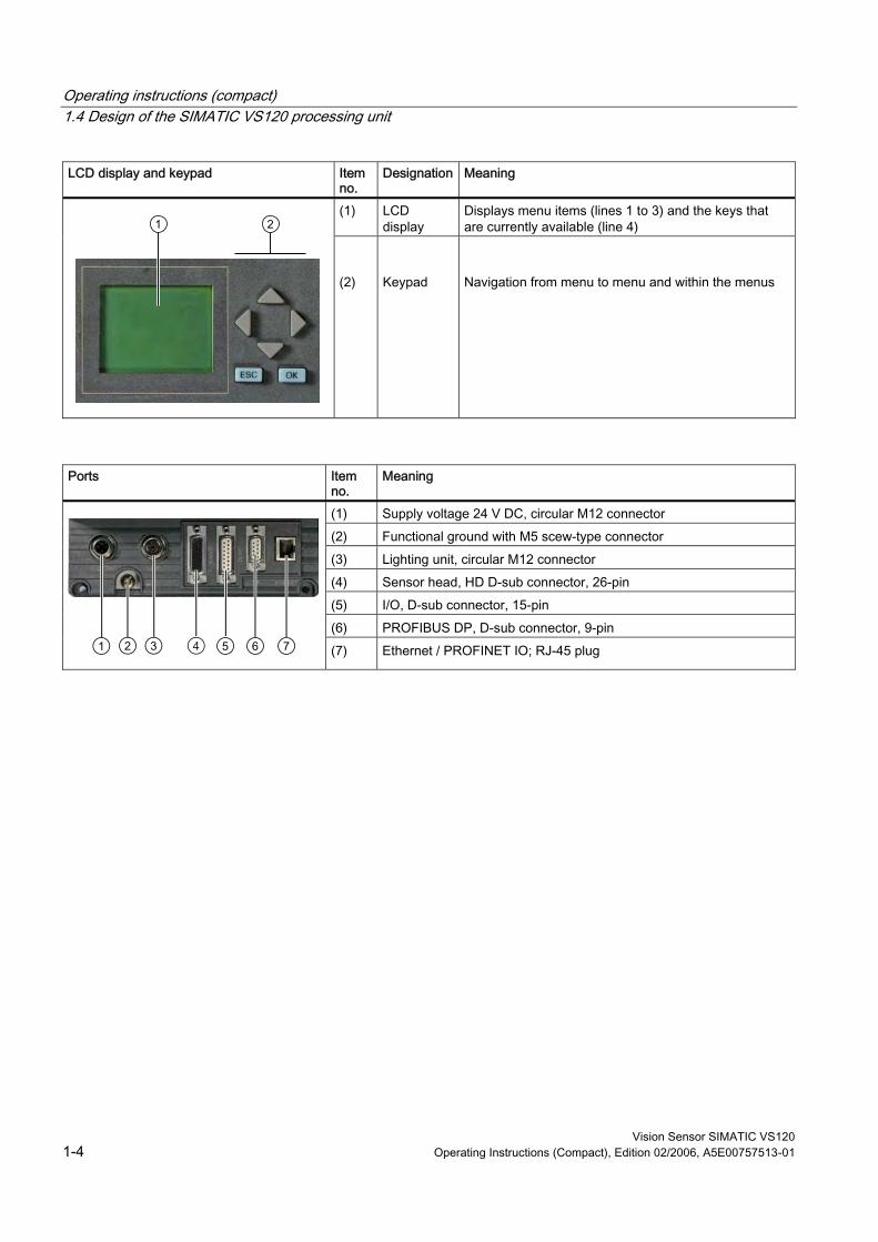
LCD display and keypad Item no.
Designation Meaning
(1) LCD display
Displays menu items (lines 1 to 3) and the keys that are currently available (line 4)
(2)
Keypad
Navigation from menu to menu and within the menus
Ports Item
no. Meaning
(1) Supply voltage 24 V DC, circular M12 connector (2) Functional ground with M5 scew-type connector (3) Lighting unit, circular M12 connector (4) Sensor head, HD D-sub connector, 26-pin (5) I/O, D-sub connector, 15-pin (6) PROFIBUS DP, D-sub connector, 9-pin
(7) Ethernet / PROFINET IO; RJ-45 plug
Operating instructions (compact) 1.5 Design of the sensor head with LED ring light
Vision Sensor SIMATIC VS120 Operating Instructions (Compact), Edition 02/2006, A5E00757513-01 1-5
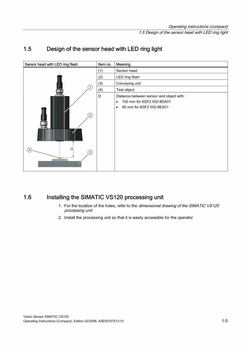
1.5 Design of the sensor head with LED ring light Sensor head with LED ring flash Item no. Meaning
(1) Sensor head (2) LED ring flash (3) Conveying unit (4) Test object
D Distance between sensor and object with: • 100 mm for 6GF2 002-8DA01 • 90 mm for 6GF2 002-8EA01
1.6 Installing the SIMATIC VS120 processing unit 1. For the location of the holes, refer to the dimensional drawing of the SIMATIC VS120
processing unit 2. Install the processing unit so that it is easily accessible for the operator
Operating instructions (compact) 1.7 Installing the sensor head with LED ring light
Vision Sensor SIMATIC VS120 1-6 Operating Instructions (Compact), Edition 02/2006, A5E00757513-01
1.7 Installing the sensor head with LED ring light
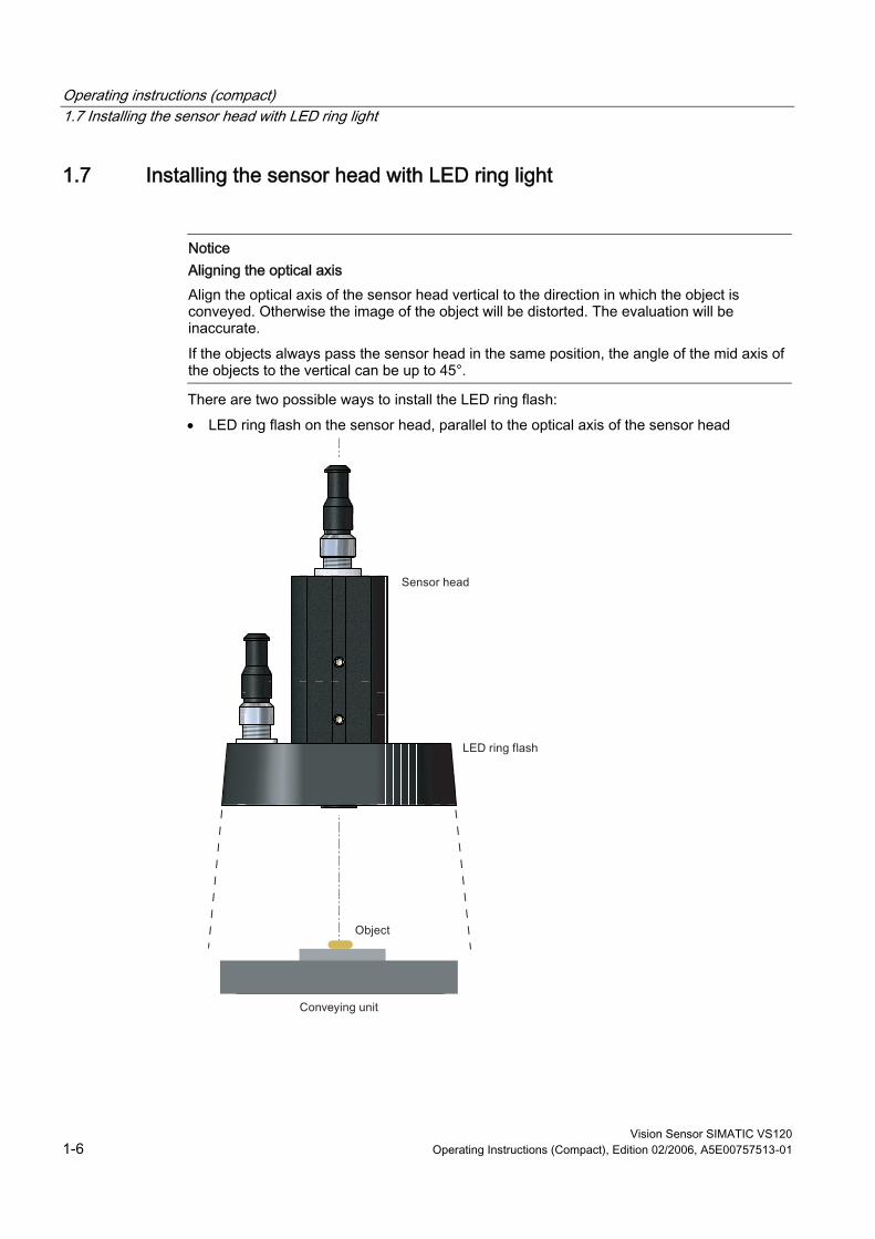
Notice Aligning the optical axis Align the optical axis of the sensor head vertical to the direction in which the object is conveyed. Otherwise the image of the object will be distorted. The evaluation will be inaccurate. If the objects always pass the sensor head in the same position, the angle of the mid axis of the objects to the vertical can be up to 45°.
There are two possible ways to install the LED ring flash: • LED ring flash on the sensor head, parallel to the optical axis of the sensor head
Operating instructions (compact) 1.7 Installing the sensor head with LED ring light
Vision Sensor SIMATIC VS120 Operating Instructions (Compact), Edition 02/2006, A5E00757513-01 1-7
How to mount the LED ring flash on the sensor head The LED ring flash is supplied with two mounting brackets to allow it to be mounted on the sensor head. 1. Screw the mounting bracket onto the LED ring sensor 2. Push the sensor head through the LED ring sensor 3. Guide the mounting brackets into the grooves of the sensor head 4. Secure the mounting bracket with screws.
How to mount the sensor head A mounting plate is supplied with the sensor head. 1. Insert the mounting plate in one of the grooves of the sensor head 2. Secure the sensor to your holder with a mounting plate
Operating instructions (compact) 1.7 Installing the sensor head with LED ring light
Vision Sensor SIMATIC VS120 1-8 Operating Instructions (Compact), Edition 02/2006, A5E00757513-01
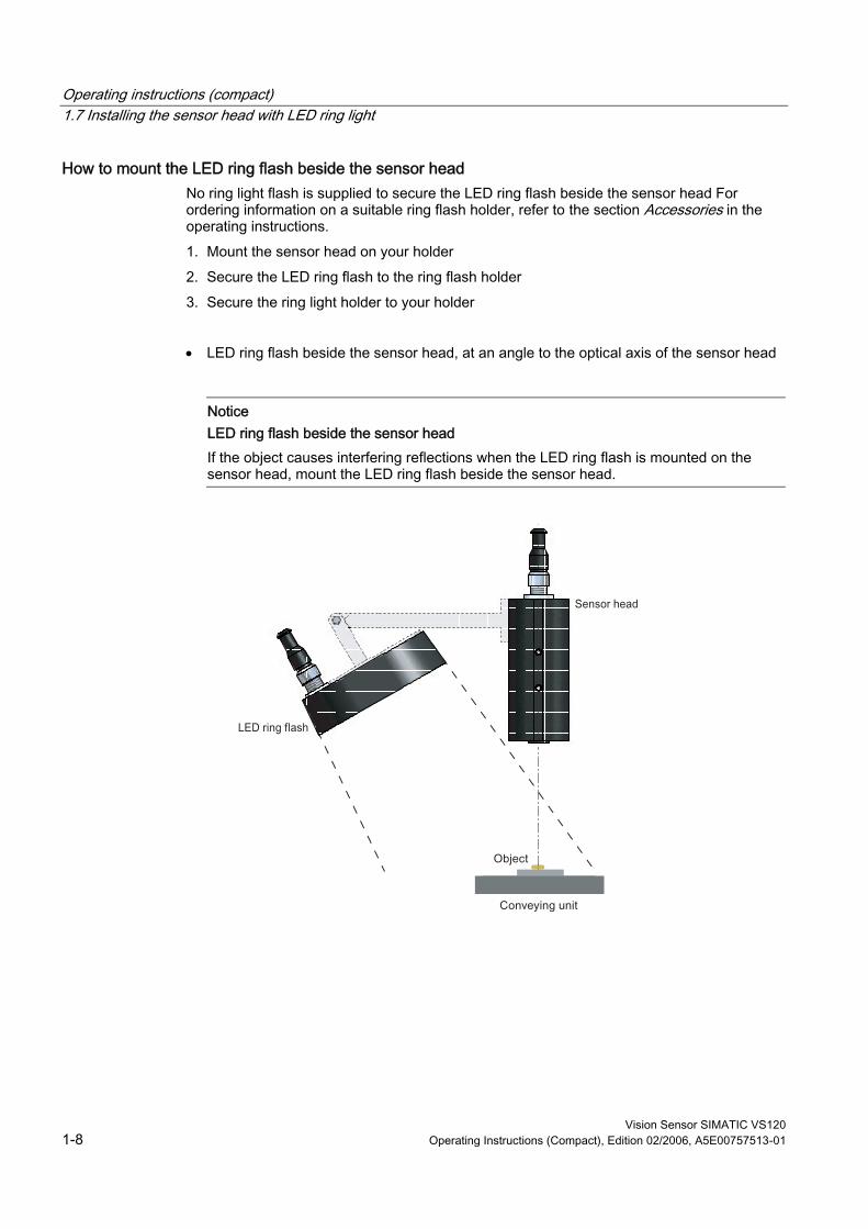
How to mount the LED ring flash beside the sensor head No ring light flash is supplied to secure the LED ring flash beside the sensor head For ordering information on a suitable ring flash holder, refer to the section Accessories in the operating instructions. 1. Mount the sensor head on your holder 2. Secure the LED ring flash to the ring flash holder 3. Secure the ring light holder to your holder • LED ring flash beside the sensor head, at an angle to the optical axis of the sensor head
Notice LED ring flash beside the sensor head If the object causes interfering reflections when the LED ring flash is mounted on the sensor head, mount the LED ring flash beside the sensor head.
Operating instructions (compact) 1.8 Connection of hardware components
Vision Sensor SIMATIC VS120 Operating Instructions (Compact), Edition 02/2006, A5E00757513-01 1-9
1.8 Connection of hardware components
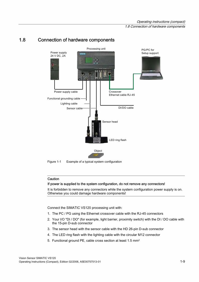
Figure 1-1 Example of a typical system configuration
Caution If power is supplied to the system configuration, do not remove any connectors! It is forbidden to remove any connectors while the system configuration power supply is on. Otherwise you could damage hardware components!
Connect the SIMATIC VS120 processing unit with: 1. The PC / PG using the Ethernet crossover cable with the RJ-45 connectors 2. Your I/O "DI / DO" (for example, light barrier, proximity switch) with the DI / DO cable with
the 15-pin D-sub connector 3. The sensor head with the sensor cable with the HD 26-pin D-sub connector 4. The LED ring flash with the lighting cable with the circular M12 connector 5. Functional ground PE, cable cross section at least 1.5 mm2
Operating instructions (compact) 1.8 Connection of hardware components
Vision Sensor SIMATIC VS120 1-10 Operating Instructions (Compact), Edition 02/2006, A5E00757513-01
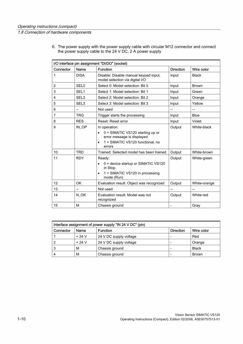
6. The power supply with the power supply cable with circular M12 connector and connect the power supply cable to the 24 V DC, 2 A power supply
I/O interface pin assignment "DI/DO" (socket) Connector Name Function Direction Wire color 1 DISA Disable: Disable manual keypad input,
model selection via digital I/O Input Black
2 SEL0 Select 0: Model selection: Bit 0 Input Brown 3 SEL1 Select 1: Model selection: Bit 1 Input Green 4 SEL2 Select 2: Model selection: Bit 2 Input Orange 5 SEL3 Select 3: Model selection: Bit 3 Input Yellow 6 -- Not used -- -- 7 TRG Trigger starts the processing Input Blue 8 RES Reset: Reset error Input Violet 9 IN_OP In operation:
• 0 = SIMATIC VS120 starting up or error message is displayed.
• 1 = SIMATIC VS120 functional, no errors
Output White-black
10 TRD Trained: Selected model has been trained. Output White-brown 11 RDY Ready:
• 0 = device startup or SIMATIC VS120 in Stop
• 1 = SIMATIC VS120 in processing mode (Run)
Output White-green
12 OK Evaluation result: Object was recognized Output White-orange 13 -- Not used -- -- 14 N_OK Evaluation result: Model was not
recognized Output White-red
15 M Chassis ground - Gray
Interface assignment of power supply "IN 24 V DC" (pin) Connector Name Function Direction Wire color 1 + 24 V 24 V DC supply voltage - Red 2 + 24 V 24 V DC supply voltage - Orange 3 M Chassis ground - Black 4 M Chassis ground - Brown

Operating instructions (compact) 1.9 Establishing a direct connection between PC / PG and processing unit
Vision Sensor SIMATIC VS120 Operating Instructions (Compact), Edition 02/2006, A5E00757513-01 1-11
1.9 Establishing a direct connection between PC / PG and processing unit To establish a direct connection between the PC / PG and processing unit: 1. Configure the SIMATIC VS120 processing unit as a DHCP server. 2. Configure the PC / PG as a DHCP client 3. Connect the SIMATIC VS120 processing unit and the PC / PG with an Ethernet
crossover RJ-45 cable With this method, the PC / PG automatically obtains its IP address from the processing unit.
Note IP address of the SIMATIC VS120 processing unit When shipped, the SIMATIC VS120 processing unit has a default IP address. You can change the IP address. For more information on this topic, read the section Manual configuration of the SIMATIC VS120 processing unit in the operating instructions.
Caution Communication problems in a network Operating the SIMATIC VS120 processing unit in a network can interfere with the communication in your network if you make certain settings in the Connect > Ports > Ethernet > IP Mode menu. You should therefore only connect the SIMATIC VS120 processing unit to the network after you have completed configuration and checked your settings carefully.

Operating instructions (compact) 1.9 Establishing a direct connection between PC / PG and processing unit
Vision Sensor SIMATIC VS120 1-12 Operating Instructions (Compact), Edition 02/2006, A5E00757513-01
How to configure the SIMATIC VS120 processing unit as a DHCP server. 1. After turning on the SIMATIC VS120 processing unit and after the self-test is completed,
go to the "Connect" menu and confirm with "OK". 2. Confirm the selected "Ports" menu with "OK" 3. Change to the "Ethernet" menu and confirm with "OK" 4. Confirm the selected "IP Mode" menu with "OK" 5. Select "DHCPSERV" and confirm with "OK"
How to configure the PC / PG as a DHCP client 1. Click Start > Settings > Network and Dial-up Connections 2. In the "Network and Dial-up Connections" dialog, select your active local area connection
to the network 3. Select "Properties" in the context-sensitive menu and select the "Internet Protocol
(TCP/IP)" entry. 4. Click the "Properties" button 5. Select the "Obtain an IP address automatically" and "Obtain DNS server address
automatically" option buttons
Operating instructions (compact) 1.10 Starting setup support via the Internet Explorer
Vision Sensor SIMATIC VS120 Operating Instructions (Compact), Edition 02/2006, A5E00757513-01 1-13
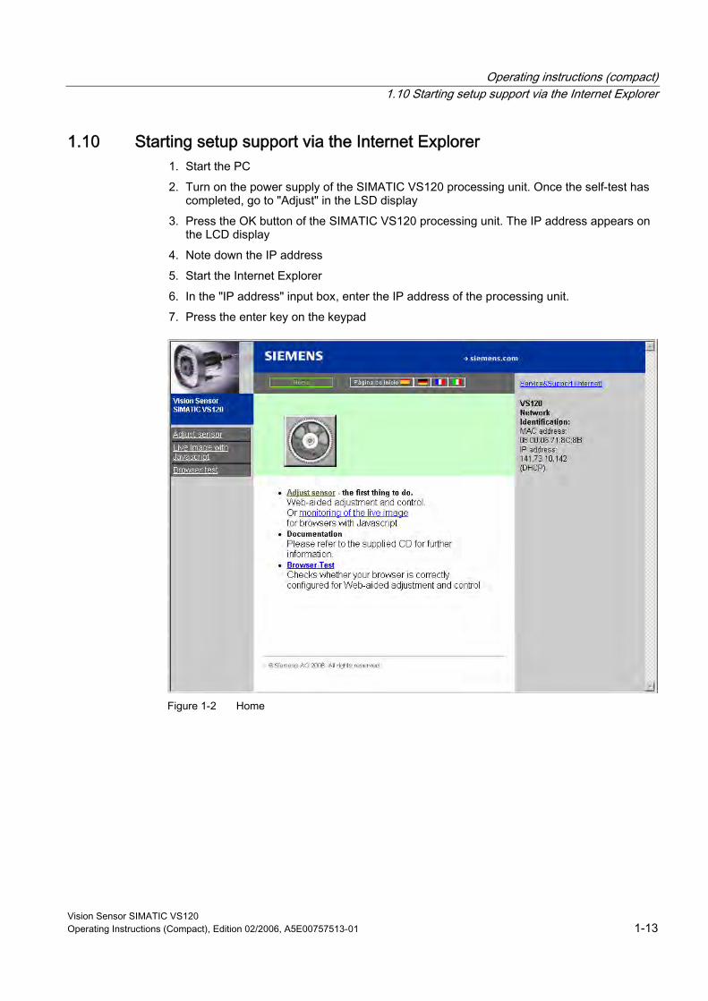
1.10 Starting setup support via the Internet Explorer 1. Start the PC 2. Turn on the power supply of the SIMATIC VS120 processing unit. Once the self-test has
completed, go to "Adjust" in the LSD display 3. Press the OK button of the SIMATIC VS120 processing unit. The IP address appears on
the LCD display 4. Note down the IP address 5. Start the Internet Explorer 6. In the "IP address" input box, enter the IP address of the processing unit. 7. Press the enter key on the keypad
Figure 1-2 Home
Operating instructions (compact) 1.11 Sensor Adjustment
Vision Sensor SIMATIC VS120 1-14 Operating Instructions (Compact), Edition 02/2006, A5E00757513-01
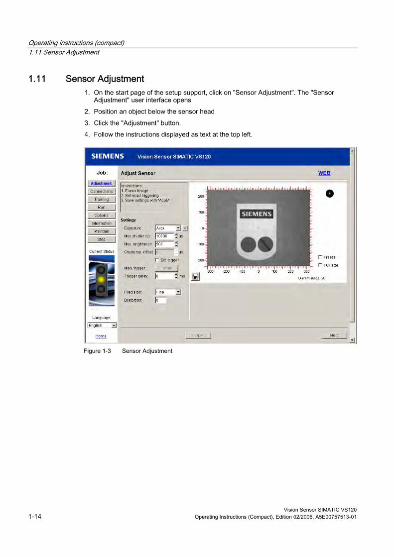
1.11 Sensor Adjustment 1. On the start page of the setup support, click on "Sensor Adjustment". The "Sensor
Adjustment" user interface opens 2. Position an object below the sensor head 3. Click the "Adjustment" button. 4. Follow the instructions displayed as text at the top left.
Figure 1-3 Sensor Adjustment
Operating instructions (compact) 1.12 Training a model
Vision Sensor SIMATIC VS120 Operating Instructions (Compact), Edition 02/2006, A5E00757513-01 1-15
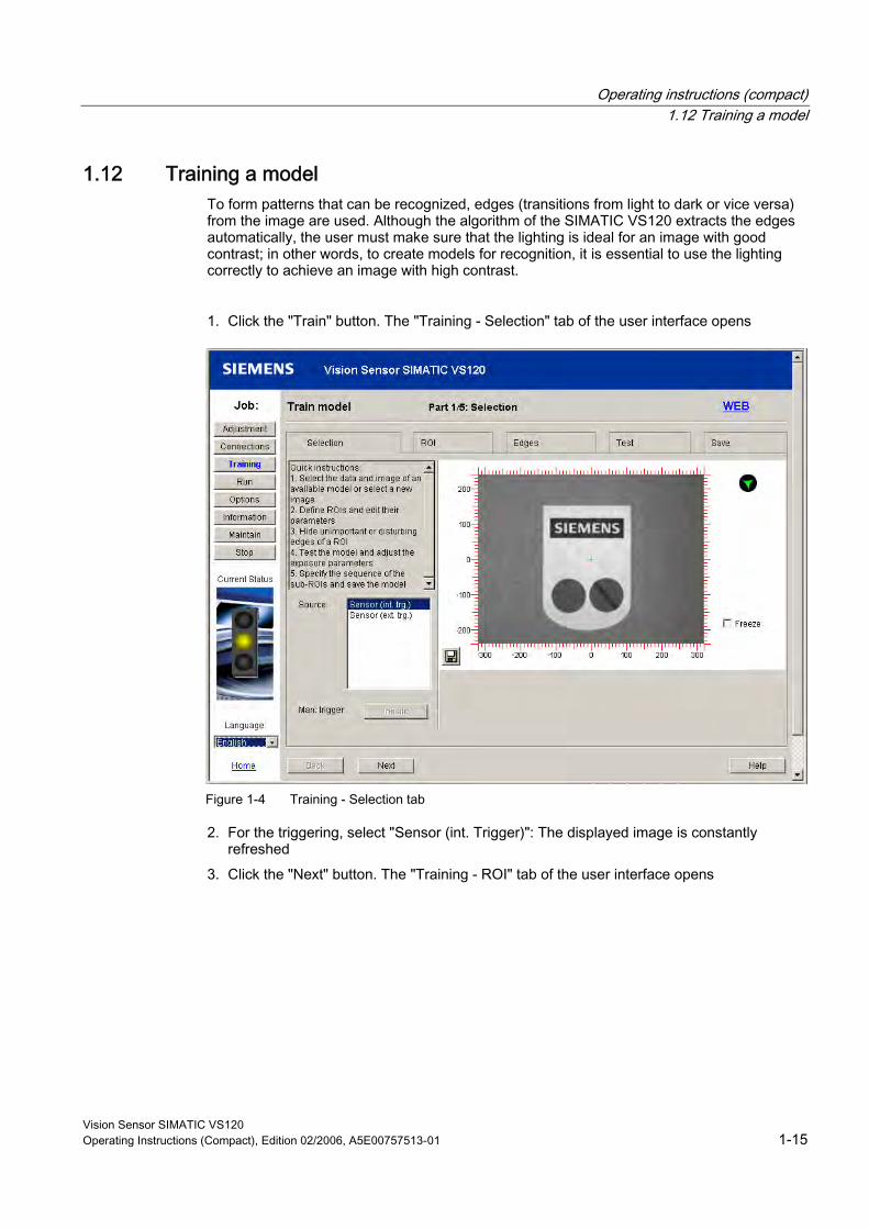
1.12 Training a model To form patterns that can be recognized, edges (transitions from light to dark or vice versa) from the image are used. Although the algorithm of the SIMATIC VS120 extracts the edges automatically, the user must make sure that the lighting is ideal for an image with good contrast; in other words, to create models for recognition, it is essential to use the lighting correctly to achieve an image with high contrast. 1. Click the "Train" button. The "Training - Selection" tab of the user interface opens
Figure 1-4 Training - Selection tab
2. For the triggering, select "Sensor (int. Trigger)": The displayed image is constantly refreshed
3. Click the "Next" button. The "Training - ROI" tab of the user interface opens
Operating instructions (compact) 1.12 Training a model
Vision Sensor SIMATIC VS120 1-16 Operating Instructions (Compact), Edition 02/2006, A5E00757513-01
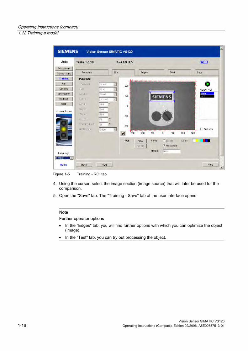
Figure 1-5 Training - ROI tab
4. Using the cursor, select the image section (image source) that will later be used for the comparison.
5. Open the "Save" tab. The "Training - Save" tab of the user interface opens
Note Further operator options • In the "Edges" tab, you will find further options with which you can optimize the object
(image). • In the "Test" tab, you can try out processing the object.
Operating instructions (compact) 1.12 Training a model
Vision Sensor SIMATIC VS120 Operating Instructions (Compact), Edition 02/2006, A5E00757513-01 1-17
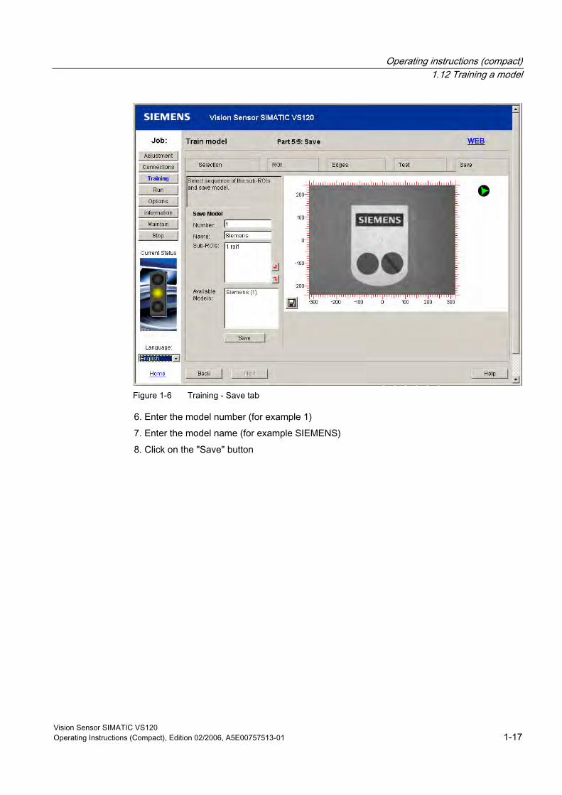
Figure 1-6 Training - Save tab
6. Enter the model number (for example 1) 7. Enter the model name (for example SIEMENS) 8. Click on the "Save" button
Operating instructions (compact) 1.13 Evaluating the object
Vision Sensor SIMATIC VS120 1-18 Operating Instructions (Compact), Edition 02/2006, A5E00757513-01
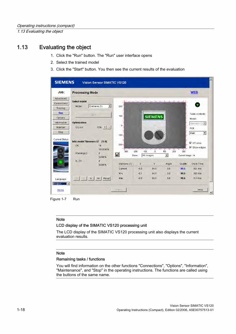
1.13 Evaluating the object 1. Click the "Run" button. The "Run" user interface opens 2. Select the trained model 3. Click the "Start" button. You then see the current results of the evaluation
Figure 1-7 Run
Note LCD display of the SIMATIC VS120 processing unit The LCD display of the SIMATIC VS120 processing unit also displays the current evaluation results.
Note Remaining tasks / functions You will find information on the other functions "Connections", "Options", "Information", "Maintenance", and "Stop" in the operating instructions. The functions are called using the buttons of the same name.

Operating instructions (compact) 1.14 Dimension drawing of the SIMATIC VS120 processing unit
Vision Sensor SIMATIC VS120 Operating Instructions (Compact), Edition 02/2006, A5E00757513-01 1-19
1.14 Dimension drawing of the SIMATIC VS120 processing unit
Figure 1-8 Dimension drawing of the processing unit
• Securing screws M4×12 or longer • Permitted, static bending radii with:
– Power supply cable with a minimum radius of 40 mm – Illumination cable with a minimum radius of 25 mm – Sensor cable with a minimum radius of 40 mm – DI / DO cable with a minimum radius of 50 mm
Operating instructions (compact) 1.15 Dimension drawing of the sensor head
Vision Sensor SIMATIC VS120 1-20 Operating Instructions (Compact), Edition 02/2006, A5E00757513-01
1.15 Dimension drawing of the sensor head
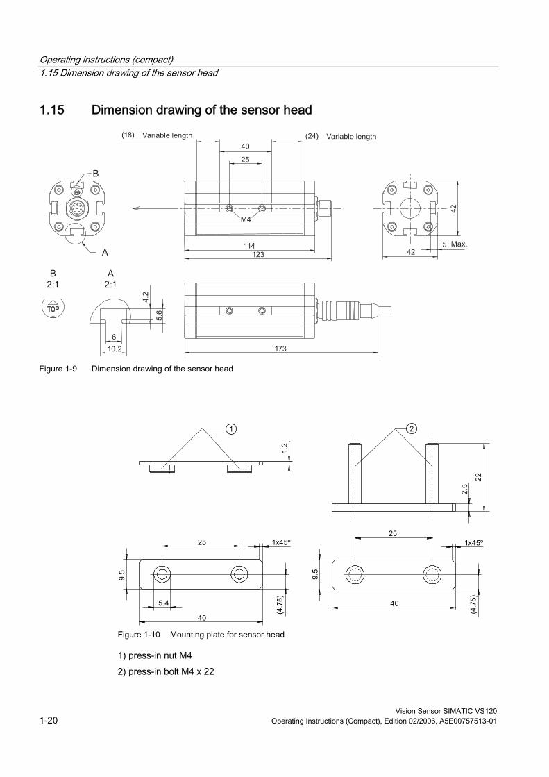
Figure 1-9 Dimension drawing of the sensor head
Figure 1-10 Mounting plate for sensor head
1) press-in nut M4 2) press-in bolt M4 x 22
Operating instructions (compact) 1.16 Dimension drawing of the LED ring flash
Vision Sensor SIMATIC VS120 Operating Instructions (Compact), Edition 02/2006, A5E00757513-01 1-21
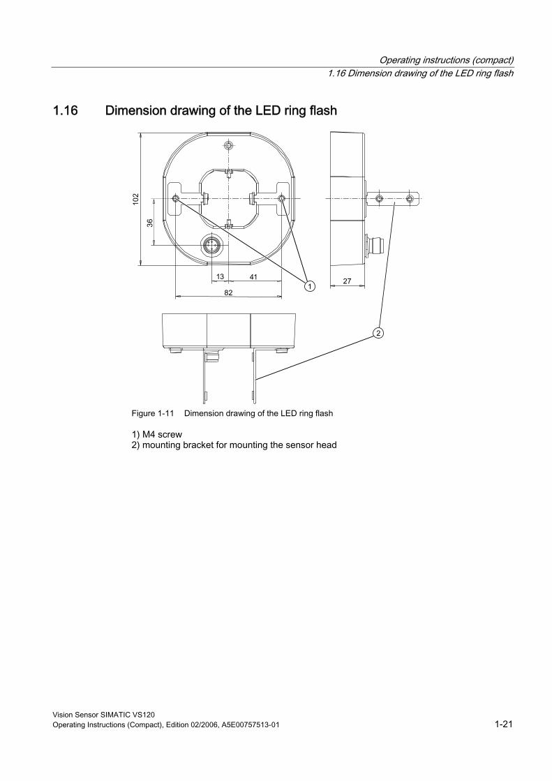
1.16 Dimension drawing of the LED ring flash
Figure 1-11 Dimension drawing of the LED ring flash
1) M4 screw 2) mounting bracket for mounting the sensor head
Operating instructions (compact) 1.17 Documentation on the SIMATIC VS120
Vision Sensor SIMATIC VS120 1-22 Operating Instructions (Compact), Edition 02/2006, A5E00757513-01
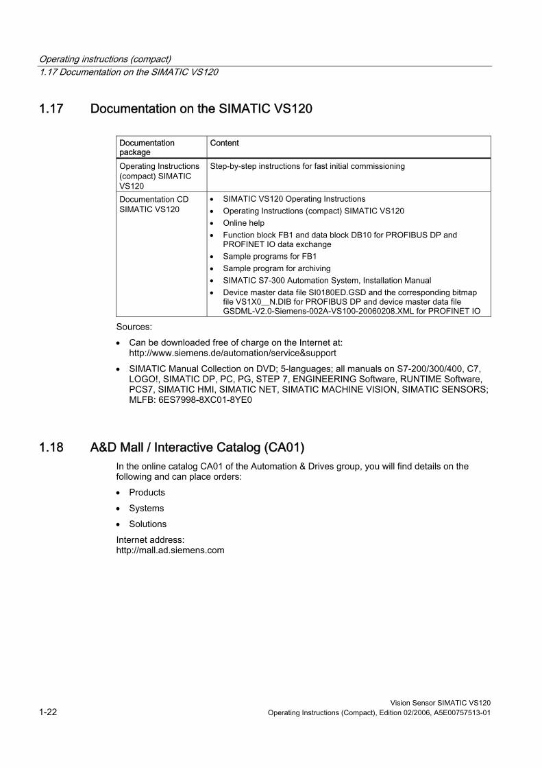
1.17 Documentation on the SIMATIC VS120
Documentation package
Content
Operating Instructions (compact) SIMATIC VS120
Step-by-step instructions for fast initial commissioning
Documentation CD SIMATIC VS120
• SIMATIC VS120 Operating Instructions • Operating Instructions (compact) SIMATIC VS120 • Online help • Function block FB1 and data block DB10 for PROFIBUS DP and
PROFINET IO data exchange • Sample programs for FB1 • Sample program for archiving • SIMATIC S7-300 Automation System, Installation Manual • Device master data file SI0180ED.GSD and the corresponding bitmap
file VS1X0__N.DIB for PROFIBUS DP and device master data file GSDML-V2.0-Siemens-002A-VS100-20060208.XML for PROFINET IO
Sources: • Can be downloaded free of charge on the Internet at:
http://www.siemens.de/automation/service&support • SIMATIC Manual Collection on DVD; 5-languages; all manuals on S7-200/300/400, C7,
LOGO!, SIMATIC DP, PC, PG, STEP 7, ENGINEERING Software, RUNTIME Software, PCS7, SIMATIC HMI, SIMATIC NET, SIMATIC MACHINE VISION, SIMATIC SENSORS; MLFB: 6ES7998-8XC01-8YE0
1.18 A&D Mall / Interactive Catalog (CA01) In the online catalog CA01 of the Automation & Drives group, you will find details on the following and can place orders: • Products • Systems • Solutions Internet address: http://mall.ad.siemens.com
Operating instructions (compact) 1.19 Service and support
Vision Sensor SIMATIC VS120 Operating Instructions (Compact), Edition 02/2006, A5E00757513-01 1-23
1.19 Service and support
Technical support You can reach the technical support team for all A&D projects at: • Telephone: ++49 (0) 180 5050 222 • Fax: ++49 (0) 180 5050 223
Internet • Visit our site on the Internet at:
http://www.siemens.com/automation/service&support • You can send a support query to:
http://www.siemens.de/automation/support-request • The online catalog and the online ordering system is available at:
http://www.siemens.de/automation/mall • For further information on factory automation sensors, visit
http://www.siemens.de/simatic-sensors

Siemens AG
Automation and DrivesIndustrial Automation SystemsPostfach 484890437 NUERNBERGFederal Republic of Germany
www.siemens.com/automation