Embed Size (px)
Citation preview

Matthias Teschner
Computer Science DepartmentUniversity of Freiburg
Image Processing and Computer Graphics
Projections andTransformations in OpenGL
University of Freiburg – Computer Science Department – Computer Graphics - 2
Motivation
for the rendering of objects in 3D space, a planar view has to be generated
3D space is projected onto a 2D plane considering external and internal camera parameters position, orientation, focal length
in homogeneous notation, 3D projections can be represented with a 4x4 transformation matrix

University of Freiburg – Computer Science Department – Computer Graphics - 3
Examples
left images 3D scene with
a view volume
right images projections onto
the viewplane
top-right parallel projection
top-bottom perspective projection
[Song Ho Ahn]

University of Freiburg – Computer Science Department – Computer Graphics - 4
Outline
2D projection
3D projection
OpenGL projection matrix
OpenGL transformation matrices

University of Freiburg – Computer Science Department – Computer Graphics - 5
Projection in 2D
a 2D projection from v onto l maps a point p onto p'
p' is the intersection ofthe line through pand v with line l
v is the viewpoint, center of perspectivity
l is the viewline the line through p
and v is a projector v is not on the line l, p ≠ v

University of Freiburg – Computer Science Department – Computer Graphics - 6
Projection in 2D
if the homogeneous component of the viewpoint vis not equal to zero, we have a perspective projection projectors are not parallel
if v is at infinity, we have a parallel projection projectors are parallel
perspective projection parallel projection

University of Freiburg – Computer Science Department – Computer Graphics - 7
Classification
location of viewpoint and orientation of the viewlinedetermine the type of projection
parallel (viewpoint at infinity, parallel projectors) orthographic (viewline orthogonal to the projectors) oblique (viewline not orthogonal to the projectors)
perspective (non-parallel projectors) one-point
(viewline intersects one principal axis, i.e. viewline is parallel to a principal axis, one vanishing point)
two-point(viewline intersects two principal axis, two vanishing points)

University of Freiburg – Computer Science Department – Computer Graphics - 8
General Case
a 2D projection is represented by matrix

University of Freiburg – Computer Science Department – Computer Graphics - 9
Example
e.g. d=-1, (1,2)T is mapped to (0,1)T

University of Freiburg – Computer Science Department – Computer Graphics - 10
Discussion
matrices M and M represent the same transformation
therefore, and represent
the same transformation
x is mapped to zero, y is scaled depending on x moving d to infinity results in parallel projection

University of Freiburg – Computer Science Department – Computer Graphics - 11
Discussion
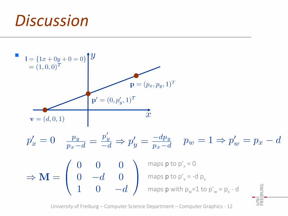
parallel projection
University of Freiburg – Computer Science Department – Computer Graphics - 12
Discussion
maps p to p'x = 0
maps p to p'y = -d py
maps p with pw=1 to p'w = px - d

University of Freiburg – Computer Science Department – Computer Graphics - 13
Discussion
2D transformation in homogeneous form
wx and wy map the homogeneous component wof a point to a value w' that depends on x and y
therefore, the scaling of a point depends on x and / or y
in perspective 3D projections, this is generally employed to scale the x- and y- component with respect to z, its distance to the viewer

University of Freiburg – Computer Science Department – Computer Graphics - 14
Outline
2D projection
3D projection
OpenGL projection matrix
OpenGL transformation matrices

University of Freiburg – Computer Science Department – Computer Graphics - 15
Projection in 3D
a 3D projection from v onto n maps a point p onto p'
p' is the intersection ofthe line through pand v with plane n
v is the viewpoint, center of perspectivity
n is the viewplane
the line through pand v is a projector
v is not on the plane n, p ≠ v

University of Freiburg – Computer Science Department – Computer Graphics - 16
General Case
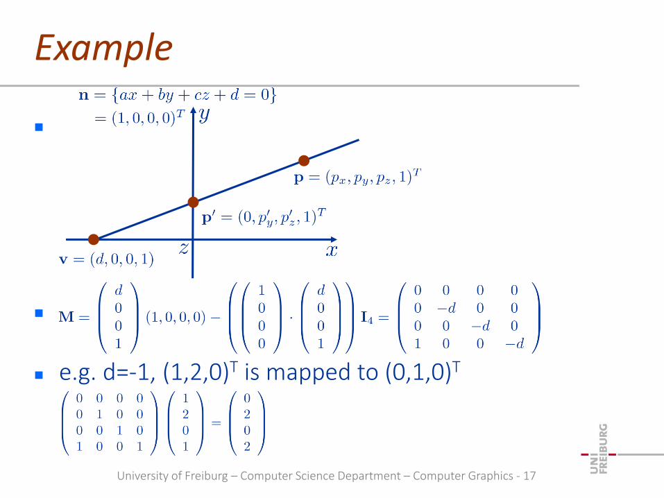
a 3D projection is represented by a matrix
University of Freiburg – Computer Science Department – Computer Graphics - 17
Example
e.g. d=-1, (1,2,0)T is mapped to (0,1,0)T

University of Freiburg – Computer Science Department – Computer Graphics - 18
Example
parallel projection onto the plane z = 0 with viewpoint / viewing direction v = (0,0,1,0)T
x- and y-component are unchanged, z is mapped to zero
remember that M and M with, e. g., =-1 represent the same transformation
University of Freiburg – Computer Science Department – Computer Graphics - 19
Outline
2D projection
3D projection
OpenGL projection matrix perspective projection
parallel projection
OpenGL transformation matrices

University of Freiburg – Computer Science Department – Computer Graphics - 20
View Volume
in OpenGL, the projection transformation maps a view volume to the canonical view volume
the view volume is specified by its boundary left, right, bottom, top, near far
the canonical view volume is a cube from (-1,-1,-1) to (1,1,1)
[Song Ho Ahn]
(l, t, f)
(x, y, f)
this transformation implementsorthographic projection
this transformation implementsperspective projection

University of Freiburg – Computer Science Department – Computer Graphics - 21
OpenGL Projection Transform
the projection transform maps from eye coordinates to clip coordinates (w-component is not necessarily one) to normalized device coordinates NDC
(x and y are normalized with respect to w, w is preserved for further processing)
the projection transform maps the x-component of a point from (left, right) to (-1, 1) the y-component of a point from (bottom, top) to (-1, 1) the z-component of a point from (near, far) to (-1, 1)
in OpenGL, near and far are negative, so the mapping incorporates a reflection (change of right-handed to left-handed)
however, in OpenGL functions, usually the negative of near and far is specified which is positive

University of Freiburg – Computer Science Department – Computer Graphics - 22
Perspective Projection
to obtain x- and y-component of a projected point, thepoint is first projected onto the near plane (viewplane)
note that n and f denote the negative near and far values
[Song Ho Ahn]

University of Freiburg – Computer Science Department – Computer Graphics - 23
Mapping of xp and yp to (-1, 1)
[Song Ho Ahn]

University of Freiburg – Computer Science Department – Computer Graphics - 24
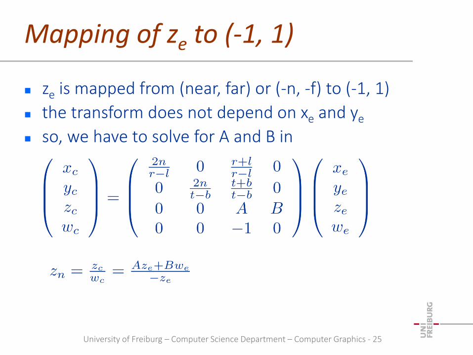
Projection Matrix
from
we get
with
clip coordinates
normalized devicecoordinates
University of Freiburg – Computer Science Department – Computer Graphics - 25
Mapping of ze to (-1, 1)
ze is mapped from (near, far) or (-n, -f) to (-1, 1)
the transform does not depend on xe and ye
so, we have to solve for A and B in
University of Freiburg – Computer Science Department – Computer Graphics - 26
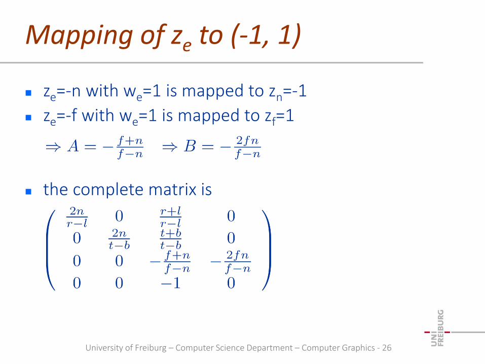
Mapping of ze to (-1, 1)
ze=-n with we=1 is mapped to zn=-1
ze=-f with we=1 is mapped to zf=1
the complete matrix is

University of Freiburg – Computer Science Department – Computer Graphics - 27
Perspective Projection Matrix
the matrix
transforms the view volume, the pyramidal frustum to the canonical view volume
[Song Ho Ahn]
pyramidal frustum

University of Freiburg – Computer Science Department – Computer Graphics - 28
Perspective Projection Matrix
projection matrix for negated values for n and f (OpenGL)
projection matrix for actual values for n and f

University of Freiburg – Computer Science Department – Computer Graphics - 29
Symmetric Setting
the matrix simplifies for r = -l and t = -b

University of Freiburg – Computer Science Department – Computer Graphics - 30
Near Plane
nonlinear mapping of ze :
varying resolution / accuracy due to fix-point representation of depth values in the depth buffer
do not move the near plane too close to zero
ze ze ze
zn zn zn

University of Freiburg – Computer Science Department – Computer Graphics - 31
Far Plane
setting the far plane to infinity is not too critical
ze
zn
University of Freiburg – Computer Science Department – Computer Graphics - 32
Outline
2D projection
3D projection
OpenGL projection matrix perspective projection
parallel projection
OpenGL transformation matrices

University of Freiburg – Computer Science Department – Computer Graphics - 33
Parallel Projection
the view volume is represented by a cuboid left, right, bottom, top, near, far
the projection transform maps the cuboid to the canonical view volume
[Song Ho Ahn]

University of Freiburg – Computer Science Department – Computer Graphics - 34
Mapping of xe, ye, ze to (-1,1)
all components of a point in eye coordinates are linearly mapped to the range of (-1,1)
linear in xe, ye, ze
combination of scale and translation
[Song Ho Ahn]

University of Freiburg – Computer Science Department – Computer Graphics - 35
Orthographic Projection Matrix
general form
simplified form for a symmetric view volume
University of Freiburg – Computer Science Department – Computer Graphics - 36
Outline
2D projection
3D projection
OpenGL projection matrix
OpenGL transformation matrices

University of Freiburg – Computer Science Department – Computer Graphics - 37
OpenGL Matrices
objects are transformed from object to eye space with the GL_MODELVIEW matrix
objects are transformed from eye space to clip space with the GL_PROJECTION matrix
colors are transformed with the color matrix GL_COLOR
texture coordinates are transformed with the texture matrix GL_TEXTURE

University of Freiburg – Computer Science Department – Computer Graphics - 38
Matrix Stack
each matrix type has a stack
the matrix on top of the stack is used
glMatrixMode(GL_PROJECTION);
glLoadIdentity();
glFrustum(left, right, bottom, top, near, far);
choose a matrix stack
the top element is replaced with I4
projection matrix P is generatedthe top element on the stack ismultiplied with P resulting in I4P

University of Freiburg – Computer Science Department – Computer Graphics - 39
Matrix Stack
glMatrixMode(GL_MODELVIEW);
glLoadIdentity();
glTranslatef(x,y,z);
glRotatef(alpha,1,0,0);
note that objects are rotated by R, followed by the translation T
choose a matrix stack
the top element is replaced with I4
translation matrix T is generatedthe top element on the stack ismultiplied with T resulting in I4T
rotation matrix R is generatedthe top element on the stack ismultiplied with R resulting in I4T R

University of Freiburg – Computer Science Department – Computer Graphics - 40
Matrix Stack
glMatrixMode(GL_MODELVIEW);
glLoadIdentity();
glTranslatef(x,y,z);
glRotatef(alpha,1,0,0);
glPush();
glTranslatef(x,y,z);
glPop();
choose a matrix stack
the top element is replaced with I4
the top element is I4T
the top element is I4TR
the top element I4TRis pushed into the stackthe newly generated top elementis initialized with I4TR
the top element is I4TRT
the top element is replaced bythe previously stored element I4TR

University of Freiburg – Computer Science Department – Computer Graphics - 41
OpenGL Matrix Functions
glPushMatrix(): push the current matrix into the current matrix stack.
glPopMatrix(): pop the current matrix from the current matrix stack.
glLoadIdentity(): set the current matrix to the identity matrix.
glLoadMatrix{fd}(m): replace the current matrix with the matrix m.
glLoadTransposeMatrix{fd}(m) : replace the current matrix with the row-major ordered matrix m.
glMultMatrix{fd}(m): multiply the current matrix by the matrix m, and update the result to the current matrix.
glMultTransposeMatrix{fd}(m): multiply the current matrix by the row-major ordered matrix m, and update the result to the current matrix.
glGetFloatv(GL_MODELVIEW_MATRIX, m): return 16 values of GL_MODELVIEW matrix to m.
note that OpenGL functions expect column-major matrices in contrast to commonly used row-major matrices

University of Freiburg – Computer Science Department – Computer Graphics - 42
Modelview Example
objects are transformed with V-1M
V=TvRv
M1..4=T1..4R1..4
implementation choose the GL_MODELVIEW stack
initialize with I4
rotate with Rv-1
translate with Tv-1
push
translate with T1
rotate with R1
render object M1
pop
…
M1M2
M3
M4V
[Akenine-Moeller et al.: Real-time Rendering]
the camera is oriented and then translated
objects are oriented and then translated
I4
Rv-1
Rv-1 ·Tv
-1 = V-1
Rv-1 · Tv
-1
Rv-1 · Tv
-1 · T1
Rv-1 · Tv
-1 · T1 · R1
Rv-1 · Tv
-1

University of Freiburg – Computer Science Department – Computer Graphics - 43
Summary
2D projection
3D projection
OpenGL projection matrix perspective projection
parallel projection
OpenGL transformation matrices

University of Freiburg – Computer Science Department – Computer Graphics - 44
References
Duncan Marsh: "Applied Geometry for Computer Graphics and CAD", Springer Verlag, Berlin, 2004.
Song Ho Ahn: "OpenGL", http://www.songho.ca/ .