Embed Size (px)
Citation preview
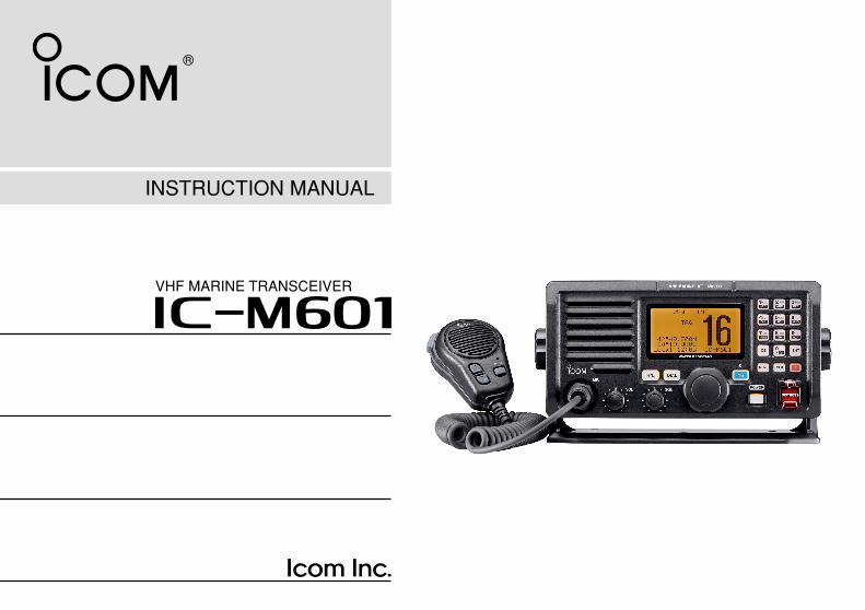
INSTRUCTION MANUAL
iM601VHF MARINE TRANSCEIVER

i
FOREWORD
Thank you for purchasing this Icom product. The IC-M601 VHF MARINE TRANSCEIVER is designed and builtwith Icom’s state of the art technology and craftsman-ship. With proper care, this product should provide youwith years of trouble-free operation.
We want to take a couple of moments of your time tothank you for making the IC-M601 your radio of choice,and hope you agree with Icom’s philosophy of “tech-nology first.” Many hours of research and developmentwent into the design of your IC-M601.
D FEATURESBuilt-in DSC meets ITU Class D requirementAn independent receiver continuously watches Ch. 70,while using another channel. Further, a single antennaconnector allows VHF and Ch. 70 operation, thus sim-plifying installation. The 10-keypad allows simple andefficient operation of the DSC emergency functions,vital for your safety at sea.
Superior receiver performanceThe IC-M601 has excellent receive specifications of morethan 75 dB for spurious response, and intermodulation
rejection. With such high level performance, receivedcalls are remarkably clear and free from noise. The pow-erful audio output from the front facing speaker furtherincreases the clarity of received calls.
Optional COMMANDMIC(2 systems are connectable)
The optional COMMANDMIC provides a 2nd and 3rdstation capability and an intercom function. With slimdimension and sizable LCD, the COMMANDMIC offersease and convenience of operating the radio fromremote locations such as the cockpit or tower up to amax. 21 m* from the IC-M601.* Requires use of optional OPC-999 extension cables.
Large LCD with dot matrix charactersThe large dot-matrix display is designed for optimumreadability in any lighting condition. With the extra largefont, the channel number is maximized on the displayand other information can be easily read.
Rugged waterproof constructionThe IC-M601 including the supplied (HM-137)/optional(HM-134) microphone has effective waterproofingequivalent to JIS waterproof grade 7*.* 1 m/30 min; except cables.
ii
Icom, Icom Inc. and the logo are registered trademarksof Icom Incorporated (Japan) in the United states, the UnitedKingdom, Germany, France, Spain, Russia and/or other coun-tries.
IMPORTANT
READ THIS INSTRUCTION MANUALCAREFULLY before attempting to operate the trans-ceiver.
SAVE THIS INSTRUCTION MANUAL. Thismanual contains important safety and operating in-structions for the IC-M601.
EXPLICIT DEFINITIONS
CLEAN THE TRANSCEIVER AND MICROPHONETHOROUGHLY WITH FRESH WATER after exposure towater including salt water, otherwise, the keys andswitches may become inoperable due to salt crystallization.
WORD DEFINITION
RRWARNINGPersonal injury, fire hazard or electricshock may occur.
CAUTION Equipment damage may occur.
NOTEIf disregarded, inconvenience only. Norisk or personal injury, fire or electricshock.
Versions of the IC-M601 which display the “CE”symbol on the serial number seal, comply with the es-sential requirements of the European Radio andTelecommunication Terminal Directive 1999/5/EC.
This warning symbol indicates that this equip-ment operates in non-harmonised frequency bandsand/or may be subject to licensing conditions in thecountry of use. Be sure to check that you have thecorrect version of this radio or the correct program-ming of this radio, to comply with national licensingrequirements.
iii
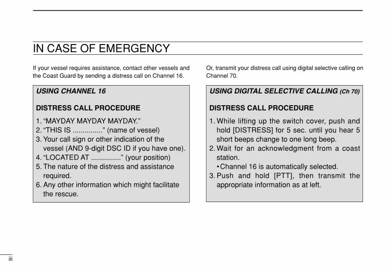
If your vessel requires assistance, contact other vessels andthe Coast Guard by sending a distress call on Channel 16.
Or, transmit your distress call using digital selective calling onChannel 70.
USING DIGITAL SELECTIVE CALLING (Ch 70)
DISTRESS CALL PROCEDURE
1. While lifting up the switch cover, push andhold [DISTRESS] for 5 sec. until you hear 5short beeps change to one long beep.
2. Wait for an acknowledgment from a coaststation.•Channel 16 is automatically selected.
3. Push and hold [PTT], then transmit theappropriate information as at left.
USING CHANNEL 16
DISTRESS CALL PROCEDURE
1. “MAYDAY MAYDAY MAYDAY.”2. “THIS IS ...............” (name of vessel)3. Your call sign or other indication of the
vessel (AND 9-digit DSC ID if you have one).4. “LOCATED AT ...............” (your position)5. The nature of the distress and assistance
required.6. Any other information which might facilitate
the rescue.
IN CASE OF EMERGENCY

FOREWORD .............................................. iIMPORTANT ............................................. iiEXPLICIT DEFINITIONS ........................... iiIN CASE OF EMERGENCY ..................... iiiTABLE OF CONTENTS ........................... ivPRECAUTION .......................................... v
1 OPERATING RULES .................. 12 PANEL DESCRIPTION .......... 2–7
Panel description ............................ 2 Function display .............................. 6 Microphone (HM-137)...................... 7
3 BASIC OPERATION ............ 8–12 Channel selection ........................... 8 Receiving and transmitting ........... 10 Call channel programming ............ 11 Channel comments ....................... 11
4 DUALWATCH/TRI-WATCH ....... 13 Description .................................... 13 Operation ...................................... 13
5 SCAN OPERATIONS ......... 14–15 Scan types .................................... 14 Setting tag channels ..................... 15 Starting a scan .............................. 15
6 DSC OPERATION .............. 16–32 MMSI code programming ............. 16 Position and time programming .... 16
Position indication ......................... 17 Distress call .................................. 18 Transmitting DSC calls ................. 19 Setting the distress information .... 23 DSC individual ID ......................... 24 Receiving DSC calls ..................... 27 DSC set mode .............................. 29 Received messages ..................... 31
7 OTHER FUNCTIONS .......... 33–36 Hailer operation ............................ 33 Automatic foghorn ......................... 34 Microphone lock function .............. 35 Intercom operation ........................ 36
8 SET MODE ........................ 37–39 Set mode programming ................ 37 Set mode items ............................. 38
9 CONNECTIONS ANDMAINTENANCE ................. 40–44 Supplied accessories .................... 40 Antenna ........................................ 40 Fuse replacement ......................... 40 Cleaning ....................................... 40 Connections .................................. 41 Mounting the transceiver .............. 42 Dimensions.................................... 44
10 TROUBLESHOOTING .............. 4511 CHANNEL LIST ........................ 46
12 SPECIFICATIONS AND OPTIONS .................................. 47 Specifications ............................... 47 Options ......................................... 47
13 HM-134 REMOTE-CONTROLMICROPHONE ................... 48–58 Panel description .......................... 48 Function display ............................ 50 Channel selection ......................... 52 Receiving and transmitting ........... 53 Lock functions ............................... 54 Display backlighting ...................... 54 Monitor function ............................ 54 Call channel programming ............ 55 Starting a scan .............................. 55 Setting tag channels ..................... 56 Dualwatch/Tri-watch operation ..... 56 Set mode programming ................ 57 Intercom operation ........................ 58 Channel comments ....................... 58
14 HM-134 CONNECTIONS AND INSTALLATION .................. 59–60 HM-134 supplied accessories .......59 Installation .....................................59
INSTALLATION NOTESHM-134 TEMPLATE
iv
TABLE OF CONTENTS 123456789101112
1413

v
RWARNING! NEVER connect the transceiver to an ACoutlet. This may pose a fire hazard or result in an electricshock.
NEVER connect the transceiver to a power source of morethan 16 V DC or use reverse polarity. This will ruin the trans-ceiver.
NEVER cut the DC power cable between the DC plug andfuse holder. If an incorrect connection is made after cutting,the transceiver may be damaged.
NEVER place the transceiver where normal operation of thevessel may be hindered or where it could cause bodily injury.
KEEP the transceiver at least 1 m away from the ship’s nav-igation compass.
DO NOT use or place the transceiver in areas with temper-atures below –20°C or above +60°C or in areas subject to di-rect sunlight, such as the dashboard.
AVOID the use of chemical agents such as benzine or al-cohol when cleaning, as they may damage the transceiversurfaces.
BE CAREFUL! The transceiver rear panel will becomehot when operating continuously for long periods.
Place the transceiver in a secure place to avoid inadvertentuse by children.
BE CAREFUL! The transceiver, HM-137 and optionalHM-134 employ waterproof construction, which correspondsto JIS waterproof specification, Grade 7 (1 m/30 min.). How-ever, once the transceiver or microphone has been dropped,waterproofing cannot be guaranteed due to the fact that thecase may be cracked, or the waterproof seal damaged, etc.
PRECAUTION
1
1OPERATING RULES
DDPRIORITIES•Read all rules and regulations pertaining to priorities andkeep an up-to-date copy handy. Safety and distress callstake priority over all others.
•You must monitor Channel 16 when you are not operatingon another channel.
•False or fraudulent distress signals are prohibited and pun-ishable by law.
DDPRIVACY• Information overheard but not intended for you cannot law-fully be used in any way.
• Indecent or profane language is prohibited.
DDRADIO LICENSES(1) SHIP STATION LICENSEYou must have a current radio station license before using thetransceiver. It is unlawful to operate a ship station which is notlicensed.
Inquire through your dealer or the appropriate governmentagency for a Ship-Radiotelephone license application. Thisgovernment-issued license states the call sign which is yourcraft’s identification for radio purposes.
(2) OPERATOR’S LICENSEA Restricted Radiotelephone Operator Permit is the licensemost often held by small vessel radio operators when a radiois not required for safety purposes.
The Restricted Radiotelephone Operator Permit must beposted or kept with the operator. Only a licensed radio opera-tor may operate a transceiver.
However, non-licensed individuals may talk over a transceiverif a licensed operator starts, supervises, ends the call andmakes the necessary log entries.
Keep a copy of the current government rules and regulationshandy.
1
PANEL DESCRIPTION
2
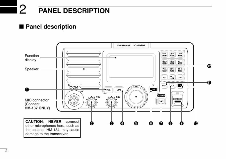
2 Panel description
VOL
iM601VHF MARINE
MIC
C
H/L DIAL 16
SQLDISTRESS
Speaker
MIC connector
Functiondisplay
q
w e r t y u oi !0
!1
!2
(Connect HM-137 ONLY)
CAUTION: NEVER connect other microphones here, such as the optional HM-134, may cause damage to the transceiver.
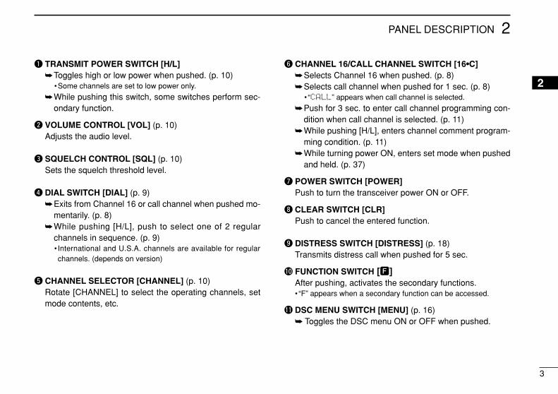
q TRANSMIT POWER SWITCH [H/L]Toggles high or low power when pushed. (p. 10)
•Some channels are set to low power only.
While pushing this switch, some switches perform sec-ondary function.
w VOLUME CONTROL [VOL] (p. 10)Adjusts the audio level.
e SQUELCH CONTROL [SQL] (p. 10)Sets the squelch threshold level.
r DIAL SWITCH [DIAL] (p. 9)Exits from Channel 16 or call channel when pushed mo-
mentarily. (p. 8)While pushing [H/L], push to select one of 2 regular
channels in sequence. (p. 9)• International and U.S.A. channels are available for regularchannels. (depends on version)
t CHANNEL SELECTOR [CHANNEL] (p. 10)Rotate [CHANNEL] to select the operating channels, setmode contents, etc.
y CHANNEL 16/CALL CHANNEL SWITCH [16•C]Selects Channel 16 when pushed. (p. 8)Selects call channel when pushed for 1 sec. (p. 8)
• “CALL” appears when call channel is selected.
Push for 3 sec. to enter call channel programming con-dition when call channel is selected. (p. 11)
While pushing [H/L], enters channel comment program-ming condition. (p. 11)
While turning power ON, enters set mode when pushedand held. (p. 37)
u POWER SWITCH [POWER]Push to turn the transceiver power ON or OFF.
i CLEAR SWITCH [CLR]Push to cancel the entered function.
o DISTRESS SWITCH [DISTRESS] (p. 18)Transmits distress call when pushed for 5 sec.
!0 FUNCTION SWITCH [F]After pushing, activates the secondary functions.• “F” appears when a secondary function can be accessed.
!1 DSC MENU SWITCH [MENU] (p. 16) Toggles the DSC menu ON or OFF when pushed.
PANEL DESCRIPTION
3
2
2

4
2 PANEL DESCRIPTION
!2 KEYPAD Inputs numeral for channel number input, etc. Inputs numeral and alphabet (some symbol) for channel
comment input.After pushing [F], turns the secondary function ON or
OFF.• [3 DIM] is necessary to rotate [CHANNEL] after pushing.•Most of secondary function (except [5 TAG], [8 FOG]) can becleared or cancelled when push [CLR] (i).
Number input: ‘1’Comment input: ‘1,’ ‘Q,’ ‘Z,’ ‘q,’ ‘z’ or spaceAfter pushing [F], turns the DUALWATCH
function ON or OFF. (p. 13)
Number input: ‘2’Comment input: ‘2,’ ‘A,’ ‘B,’ ‘C,’ ‘a,’ ‘b’ or ‘c’After pushing [F], turns the TRI-WATCH func-
tion ON or OFF. (p. 13)
Number input: ‘3’Comment input: ‘3,’ ‘D,’ ‘E,’ ‘F,’ ‘d,’ ‘e’ or ‘f’After pushing [F], push this switch and rotate
[CHANNEL] to adjust the brightness of theLCD and switch backlight.
Number input: ‘4’Comment input ‘4,’ ‘G,’ ‘H,’ ‘I,’ ‘g,’ ‘h’ or ‘i’After pushing [F], starts or stops the SCAN
function. (p. 15)
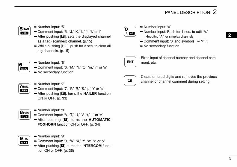
5
2PANEL DESCRIPTION
Number input: ‘5’Comment input: ‘5,’ ‘J,’ ‘K,’ ‘L,’ ‘j,’ ‘k’ or ‘l’After pushing [F], sets the displayed channel
as a tag (scanned) channel. (p.15)While pushing [H/L], push for 3 sec. to clear all
tag channels. (p.15)
Number input: ‘6’Comment input: ‘6,’ ‘M,’ ‘N,’ ‘O,’ ‘m,’ ‘n’ or ‘o’No secondary function
Number input: ‘7’Comment input: ‘7,’ ‘P,’ ‘R,’ ‘S,’ ‘p,’ ‘r’ or ‘s’After pushing [F], turns the HAILER function
ON or OFF. (p. 33)
Number input: ‘8’Comment input: ‘8,’ ‘T,’ ‘U,’ ‘V,’ ‘t,’ ‘u’ or ‘v’After pushing [F], turns the AUTOMATIC
FOGHORN function ON or OFF. (p. 34)
Number input: ‘9’Comment input: ‘9,’ ‘W,’ ‘X,’ ‘Y,’ ‘w,’ ‘x’ or ‘y’After pushing [F], turns the INTERCOM func-
tion ON or OFF. (p. 36)
Number input: ‘0’Number input: Push for 1 sec. to edit ‘A.’
• Inputing “A” for simplex channels.
Comment input: ‘0’ and symbols (‘–’ ‘/’ ‘.’)No secondary function
Fixes input of channel number and channel com-ment, etc.
Clears entered digits and retrieves the previouschannel or channel comment during setting.
2
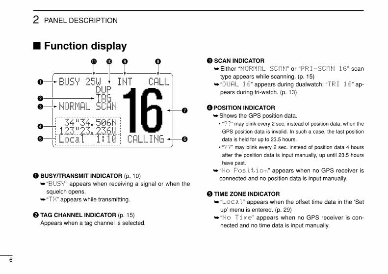
Function display
q BUSY/TRANSMIT INDICATOR (p. 10) “BUSY” appears when receiving a signal or when the
squelch opens. “TX” appears while transmitting.
w TAG CHANNEL INDICATOR (p. 15)Appears when a tag channel is selected.
e SCAN INDICATOREither “NORMAL SCAN” or “PRI-SCAN 16” scan
type appears while scanning. (p. 15) “DUAL 16” appears during dualwatch; “TRI 16” ap-
pears during tri-watch. (p. 13)
rPOSITION INDICATORShows the GPS position data.
• “??” may blink every 2 sec. instead of position data; when the
GPS position data is invalid. In such a case, the last position
data is held for up to 23.5 hours.
• “??” may blink every 2 sec. instead of position data 4 hours
after the position data is input manually, up until 23.5 hours
have past.
“No Position” appears when no GPS receiver isconnected and no position data is input manually.
t TIME ZONE INDICATOR “Local” appears when the offset time data in the ‘Set
up’ menu is entered. (p. 29) “No Time” appears when no GPS receiver is con-
nected and no time data is input manually.
BUSY-25W---INT---CALLLOCAL--DUPSCRAM--TAGNORMAL-SCAN
-34"34.506N123"23.236WLocal--1:10--CALLING
q
w
r
t
e
!1 !0 o i
u
y
PANEL DESCRIPTION
6
2
7
2PANEL DESCRIPTION
Microphone (HM-137)
q PTT SWITCH [PTT] (p. 10)Push and hold to transmit; release to receive.
w CHANNEL UP/DOWN SWITCHES [YY]/[ZZ] (p. 10)Push either switch to change the operating channel, setmode contents, etc.
e CHANNEL 16/CALL CHANNEL SWITCH [16/C]Push to select Channel 16; push for 1 sec. to Channel 9.
(p. 8)While pushing [16/C], turn power ON to toggle the lock
function ON or OFF. (p. 35)
Speaker
Microphone
w
q
e16/C
y CHANNEL COMMENT INDICATORChannel comment appears if programmed. (p. 11) “Low Batt” flashes when the battery voltage drops to
approx. 10 V DC or below.
u CHANNEL NUMBER READOUTIndicates the selected operating channel number. • “A” appears when a simplex channel is selected. (p. 9)• “F” appears when [F] is pushed.
i CALL CHANNEL INDICATOR (p. 8)“CALL” appears when the call channel is selected.
o CHANNEL GROUP INDICATOR (p. 9)Indicates whether an International “INT” or U.S.A. “USA”channel is selected. (depends on version)
!0 DUPLEX INDICATOR (p. 9)Appears when a duplex channel is selected.•Duplex channel has a different transmit frequency and receiving
frequency.
!1 POWER INDICATOR (p. 10) “25W” appears when high power is selected. “1W” appears when low power is selected.
2
8
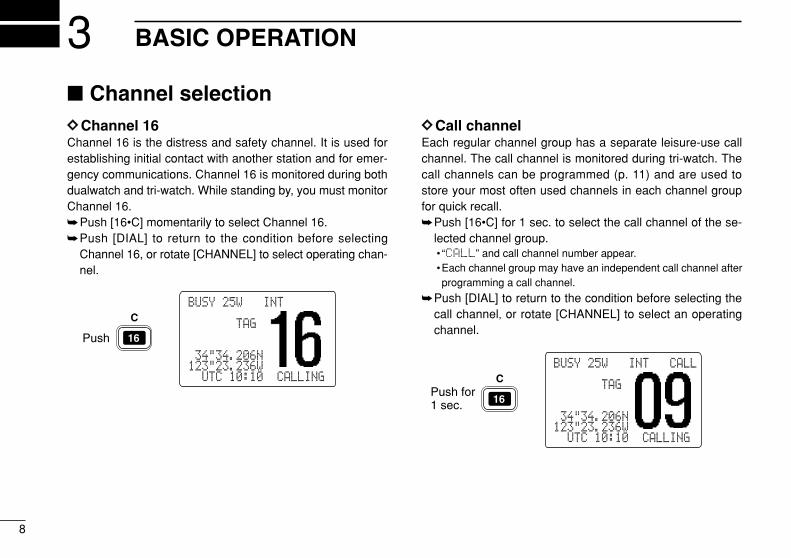
3 BASIC OPERATION
Channel selectionDDChannel 16Channel 16 is the distress and safety channel. It is used forestablishing initial contact with another station and for emer-gency communications. Channel 16 is monitored during bothdualwatch and tri-watch. While standing by, you must monitorChannel 16.Push [16•C] momentarily to select Channel 16.Push [DIAL] to return to the condition before selecting
Channel 16, or rotate [CHANNEL] to select operating chan-nel.
DDCall channelEach regular channel group has a separate leisure-use callchannel. The call channel is monitored during tri-watch. Thecall channels can be programmed (p. 11) and are used tostore your most often used channels in each channel groupfor quick recall.Push [16•C] for 1 sec. to select the call channel of the se-
lected channel group.• “CALL” and call channel number appear. •Each channel group may have an independent call channel afterprogramming a call channel.
Push [DIAL] to return to the condition before selecting thecall channel, or rotate [CHANNEL] to select an operatingchannel.
Push for1 sec.
C
16
BUSY-25W---INT---CALLLOCAL--DUPSCRAM--TAGNORMAL-SCAN
-34"34.206N123"23.236W--UTC-10:10--CALLING
Push
C
16
BUSY-25W---INT---CALLLOCAL--DUPSCRAM--TAGNORMAL-SCAN
-34"34.206N123"23.236W--UTC-10:10--CALLING
3BASIC OPERATION
9
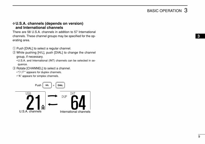
DDU.S.A. channels (depends on version)and International channels
There are 58 U.S.A. channels in addition to 57 Internationalchannels. These channel groups may be specified for the op-erating area.
q Push [DIAL] to select a regular channel.w While pushing [H/L], push [DIAL] to change the channel
group, if necessary.•U.S.A. and International (INT) channels can be selected in se-quence.
e Rotate [CHANNEL] to select a channel.• “DUP” appears for duplex channels.• “A” appears for simplex channels.
Push +
U.S.A. channels
H/L DIAL
International channels
INTDUP
USA
3
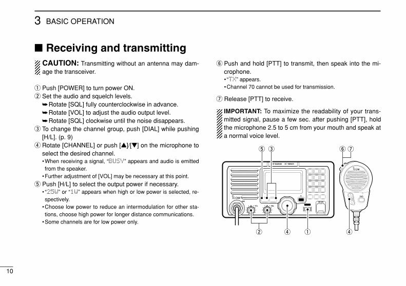
Receiving and transmittingCAUTION: Transmitting without an antenna may dam-age the transceiver.
q Push [POWER] to turn power ON.w Set the audio and squelch levels.
Rotate [SQL] fully counterclockwise in advance.Rotate [VOL] to adjust the audio output level.Rotate [SQL] clockwise until the noise disappears.
e To change the channel group, push [DIAL] while pushing[H/L]. (p. 9)
r Rotate [CHANNEL] or push [Y]/[Z] on the microphone toselect the desired channel.•When receiving a signal, “BUSY” appears and audio is emittedfrom the speaker.
•Further adjustment of [VOL] may be necessary at this point.
t Push [H/L] to select the output power if necessary.• “25W” or “1W” appears when high or low power is selected, re-spectively.
•Choose low power to reduce an intermodulation for other sta-tions, choose high power for longer distance communications.
•Some channels are for low power only.
y Push and hold [PTT] to transmit, then speak into the mi-crophone.• “TX” appears.•Channel 70 cannot be used for transmission.
u Release [PTT] to receive.
IMPORTANT: To maximize the readability of your trans-mitted signal, pause a few sec. after pushing [PTT], holdthe microphone 2.5 to 5 cm from your mouth and speak ata normal voice level.
VOL
iM601VHF MARINE
MIC
C
SQL
16/C
w
e
q rr
t y u
3 BASIC OPERATION
10
3BASIC OPERATION
11
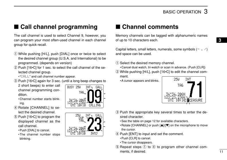
Call channel programmingThe call channel is used to select Channel 9, however, youcan program your most often-used channel in each channelgroup for quick recall.
q While pushing [H/L], push [DIAL] once or twice to selectthe desired channel group (U.S.A. and International) to beprogrammed. (depends on version)
w Push [16•C] for 1 sec. to select the call channel of the se-lected channel group.• “CALL” and call channel number appear.
e Push [16•C] again for 3 sec. (until a long beep changes to2 short beeps) to enter callchannel programming con-dition.•Channel number starts blink-ing.
r Rotate [CHANNEL] to se-lect the desired channel.
t Push [16•C] to program thedisplayed channel as thecall channel.•Push [DIAL] to cancel.•The channel number stopsblinking.
Channel commentsMemory channels can be tagged with alphanumeric namesof up to 10 characters each.
Capital letters, small letters, numerals, some symbols (- ./)and space can be used.
q Select the desired memory channel.•Cancel dual watch, tri-watch or scan in advance. (Push [CLR])
w While pushing [H/L], push [16•C] to edit the channel com-ment.•A cursor appears and blinks.
e Push the appropriate key several times to enter the de-sired character.•See the table on page 12 for available characters.•Rotate [CHANNEL] or push [Y]/[Z] on the microphone to movethe cursor.
r Push [ENT] to input and set the comment.•Push [CLR] to cancel.•The cursor disappears.
t Repeat steps q to r to program other channel com-ments, if desired.
BUSYBUSY-25W25W------INTINT------CALLCALLLOCAL--DUPLOCAL--DUPSCRAMSCRAM----TAGTAGNORMAL-SCANNORMAL-SCAN
-34"34.206N34"34.206N123"23.236W123"23.236W----UTCUTC-10:1010:10----CALLINGCALLING
BUSYBUSY-25W25W------INTINT------CALLCALLLOCAL--LOCAL--DUPDUPSCRAMSCRAM----TAGTAGNORMAL-SCANNORMAL-SCAN
-34"34.206N34"34.206N123"23.236W123"23.236W----UTCUTC-10:1010:10------INTLINTL
BUSY-BUSY-25W25W------INTINT------CALLCALLLOCAL--LOCAL--DUPDUPSCRAMSCRAM----TAGTAGNORMAL-SCANNORMAL-SCAN
-34"34.206N34"34.206N123"23.236W123"23.236W----UTCUTC-10:1010:10-PLEASURELEASURE
3
12
3 BASIC OPERATION
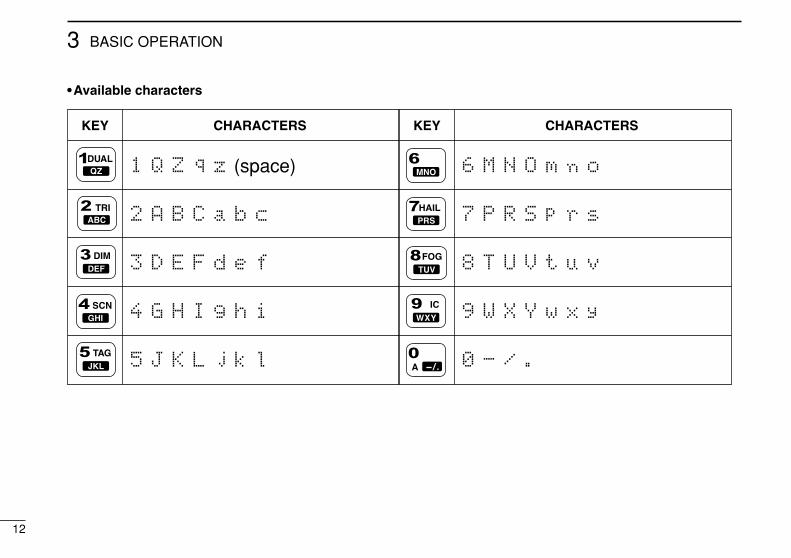
KEY CHARACTERS KEY CHARACTERS
1
2
3
4
5
Q
A
D
G
J
Z
B
E
H
K
q
C
F
I
L
z (space)
a
d
g
j
b
e
h
k
c
f
i
l
6
7
8
9
0
M
P
T
W
-
N
R
U
X
/
O
S
V
Y
.
m n o
p
t
w
r
u
x
s
v
y
•Available characters
13
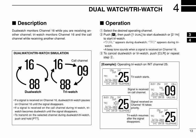
4DUAL WATCH/TRI-WATCH
DescriptionDualwatch monitors Channel 16 while you are receiving an-other channel; tri-watch monitors Channel 16 and the callchannel while receiving another channel.
Operationq Select the desired operating channel.w Push [F], then push [1 DUAL] to start dualwatch or [2 TRI]
to start tri-watch.• “DUAL” appears during dualwatch; “TRI” appears during tri-watch.
•A beep tone sounds when a signal is received on Channel 16.
e To cancel dualwatch or tri-watch, push [CLR] or repeatstep w.
[Example]: Operating tri-watch on INT channel 25.
DUALWATCH/TRI-WATCH SIMULATION
• If a signal is received on Channel 16, dualwatch/tri-watch pauses
on Channel 16 until the signal disappears.• If a signal is received on the call channel during tri-watch, tri-watch becomes dualwatch until the signal disappears.
•To transmit on the selected channel during dualwatch/tri-watch,push and hold [PTT].
Call channel
Dualwatch Tri-watch
BUSY-25W---INT---CALLLOCAL--DUPSCRAM--TAGTRIMAL-SC16
-34"34.206N123"23.236W--UTC-10:10-TELEPHONE
BUSY-25W---INT---CALLLOCAL--DUPSCRAM--TAGTRIMAL-SC16
-34"34.206N123"23.236W--UTC-10:10-TELEPHONE
BUSY-25W---INT---CALLLOCAL--DUPSCRAM--TAGTRIMAL-SC16
-34"34.206N123"23.236W--UTC-10:10-TELEPHONE
BUSY-25W---INT---CALLLOCAL--DUPSCRAM--TAGTRIMAL-SC16
-34"34.206N123"23.236W--UTC-10:10--CALLING
Tri-watch starts.
Signal is received on call channel.
Signal received on Channel 16 takes priority.
Tri-watch resumes after the signal disappears.
43
5 SCAN OPERATIONS
14
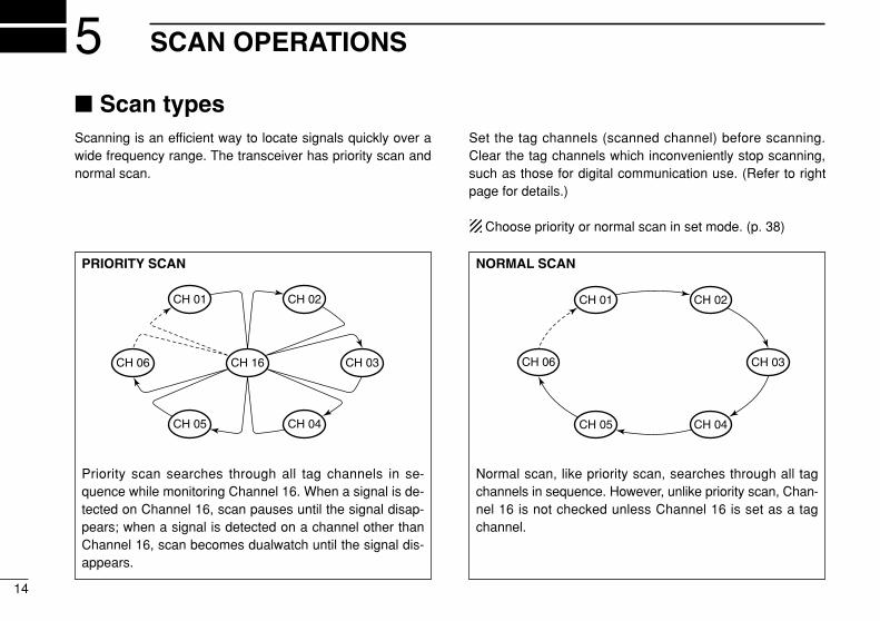
Scan typesScanning is an efficient way to locate signals quickly over awide frequency range. The transceiver has priority scan andnormal scan.
Set the tag channels (scanned channel) before scanning.Clear the tag channels which inconveniently stop scanning,such as those for digital communication use. (Refer to rightpage for details.)
Choose priority or normal scan in set mode. (p. 38)
NORMAL SCAN
Normal scan, like priority scan, searches through all tagchannels in sequence. However, unlike priority scan, Chan-nel 16 is not checked unless Channel 16 is set as a tagchannel.
CH 01 CH 02
CH 06
CH 05 CH 04
CH 03
PRIORITY SCAN
Priority scan searches through all tag channels in se-quence while monitoring Channel 16. When a signal is de-tected on Channel 16, scan pauses until the signal disap-pears; when a signal is detected on a channel other thanChannel 16, scan becomes dualwatch until the signal dis-appears.
CH 06
CH 01
CH 16
CH 02
CH 05 CH 04
CH 03
5SCAN OPERATION
15
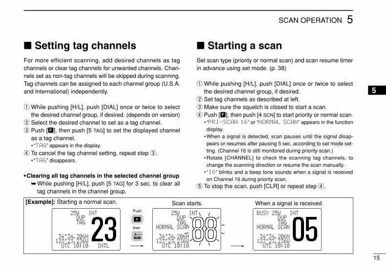
Push
SCNGHI
then
Scan starts. When a signal is received
BUSY-25W---INT---CALLLOCAL--DUPSCRAM--TAGNORMAL-SCAN
-34"34.206N123"23.236W--UTC-10:10---INTL-
BUSY-25W---INT---CALLLOCAL--DUPSCRAM--TAGNORMAL-SCAN
-34"34.206N123"23.236W--UTC-10:10---INTL-
4
BUSY-25W---INT---CALLLOCAL--DUPSCRAM--TAGNORMAL-SCAN
-34"34.206N123"23.236W--UTC-10:10---INTL-
[Example]: Starting a normal scan.
Setting tag channelsFor more efficient scanning, add desired channels as tagchannels or clear tag channels for unwanted channels. Chan-nels set as non-tag channels will be skipped during scanning.Tag channels can be assigned to each channel group (U.S.A.and International) independently.
q While pushing [H/L], push [DIAL] once or twice to selectthe desired channel group, if desired. (depends on version)
w Select the desired channel to set as a tag channel.e Push [F], then push [5 TAG] to set the displayed channel
as a tag channel.• “TAG” appears in the display.
r To cancel the tag channel setting, repeat step e.• “TAG” disappears.
•Clearing all tag channels in the selected channel groupWhile pushing [H/L], push [5 TAG] for 3 sec. to clear all
tag channels in the channel group.
Starting a scanSet scan type (priority or normal scan) and scan resume timerin advance using set mode. (p. 38)
q While pushing [H/L], push [DIAL] once or twice to selectthe desired channel group, if desired.
w Set tag channels as described at left.e Make sure the squelch is closed to start a scan.r Push [F], then push [4 SCN] to start priority or normal scan.
• “PRI-SCAN 16” or “NORMAL SCAN” appears in the functiondisplay.
•When a signal is detected, scan pauses until the signal disap-pears or resumes after pausing 5 sec. according to set mode set-ting. (Channel 16 is still monitored during priority scan.)
•Rotate [CHANNEL] to check the scanning tag channels, tochange the scanning direction or resume the scan manually.
• “16” blinks and a beep tone sounds when a signal is receivedon Channel 16 during priority scan.
t To stop the scan, push [CLR] or repeat step r.
5
16
6 DSC OPERATION
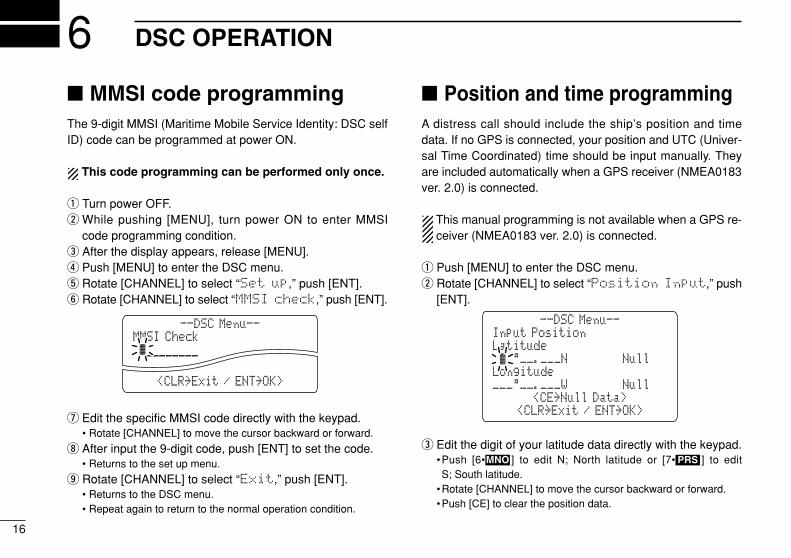
MMSI code programmingThe 9-digit MMSI (Maritime Mobile Service Identity: DSC selfID) code can be programmed at power ON.
This code programming can be performed only once.
q Turn power OFF.w While pushing [MENU], turn power ON to enter MMSI
code programming condition.e After the display appears, release [MENU].r Push [MENU] to enter the DSC menu.t Rotate [CHANNEL] to select “Set up,” push [ENT].y Rotate [CHANNEL] to select “MMSI check,” push [ENT].
u Edit the specific MMSI code directly with the keypad.• Rotate [CHANNEL] to move the cursor backward or forward.
i After input the 9-digit code, push [ENT] to set the code.• Returns to the set up menu.
o Rotate [CHANNEL] to select “Exit,” push [ENT].• Returns to the DSC menu.• Repeat again to return to the normal operation condition.
Position and time programmingA distress call should include the ship’s position and timedata. If no GPS is connected, your position and UTC (Univer-sal Time Coordinated) time should be input manually. Theyare included automatically when a GPS receiver (NMEA0183ver. 2.0) is connected.
This manual programming is not available when a GPS re-ceiver (NMEA0183 ver. 2.0) is connected.
q Push [MENU] to enter the DSC menu.w Rotate [CHANNEL] to select “Position Input,” push
[ENT].
e Edit the digit of your latitude data directly with the keypad.•Push [6• ] to edit N; North latitude or [7• ] to edit S; South latitude.
•Rotate [CHANNEL] to move the cursor backward or forward.•Push [CE] to clear the position data.
PRSMNO
Input PositionLatitude
Longitude
--DSC Menu--
<CE˘Null Data>___°__.___W˘˘˘˘˘˘˘˘Null
˘K_°__.___N˘˘˘˘˘˘˘˘Null
<CLR˘Exit / ENT˘OK>
MMSI Check˘ä________________
--DSC Menu--
<CLR˘Exit / ENT˘OK>
17
6DSC OPERATION
r Edit the digit of your longitude data directly with the keypad.•Push [3• ] to edit E; East longitude or [9• ] to edit W; West longitude.
•Rotate [CHANNEL] to move the cursor backward or forward.•Push [CE] to clear the position data.
t Push [ENT] to set the position and advance to the time set-ting condition.•Push [CLR] to abandon the setting and exit the condition to theDSC menu.
y Edit the digit of the current UTC time directly with the key-pad.•Rotate [CHANNEL] to move the cursor backward or forward.•Push [CE] to clear the time.
u Push [ENT] to set the time.•Push [CLR] to abandon the setting and exit the condition.
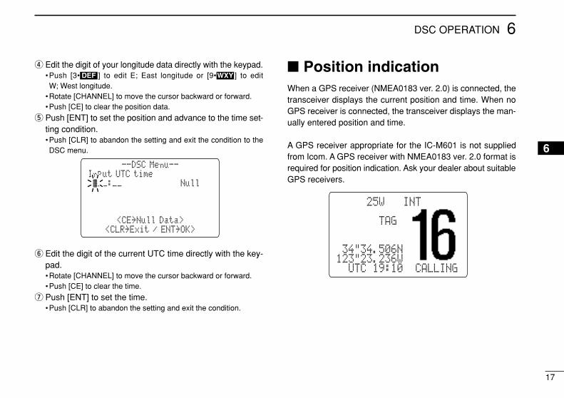
Position indicationWhen a GPS receiver (NMEA0183 ver. 2.0) is connected, thetransceiver displays the current position and time. When noGPS receiver is connected, the transceiver displays the man-ually entered position and time.
A GPS receiver appropriate for the IC-M601 is not suppliedfrom Icom. A GPS receiver with NMEA0183 ver. 2.0 format isrequired for position indication. Ask your dealer about suitableGPS receivers.
BUSY-25W---INT---CALLLOCAL--DUPSCRAM--TAGNORMAL-SCAN
-34"34.506N123"23.236W--UTC-19:10--CALLING
Input UTC time˘K__:__˘˘˘˘˘˘˘˘˘˘˘˘Null
--DSC Menu--
<CE˘Null Data><CLR˘Exit / ENT˘OK>
WXYDEF
6
18
6 DSC OPERATION
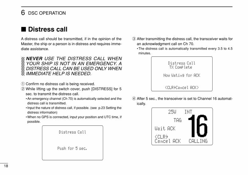
Distress callA distress call should be transmitted, if in the opinion of theMaster, the ship or a person is in distress and requires imme-diate assistance.
NEVER USE THE DISTRESS CALL WHENYOUR SHIP IS NOT IN AN EMERGENCY. ADISTRESS CALL CAN BE USED ONLY WHENIMMEDIATE HELP IS NEEDED.
q Confirm no distress call is being received.w While lifting up the switch cover, push [DISTRESS] for 5
sec. to transmit the distress call.•An emergency channel (Ch 70) is automatically selected and thedistress call is transmitted.
• Input the nature of distress call, if possible. (see p.23 Setting thedistress information)
•When no GPS is connected, input your position and UTC time, ifpossible.
e After transmitting the distress call, the transceiver waits foran acknowledgment call on Ch 70.•The distress call is automatically transmitted every 3.5 to 4.5minutes.
r After 5 sec., the transceiver is set to Channel 16 automat-ically.
BUSY-25W---INT---CALLLOCAL--DUPSCRAM--TAGNORMAL-SCANWait ACK-34"34.506N<CLR˘Cancel ACK---CALLING
Distress CallTX Complete
Now Wating for ACK
<CLR˘Cancel ACK>
Distress Call
Push for 5 sec.
19
6DSC OPERATION
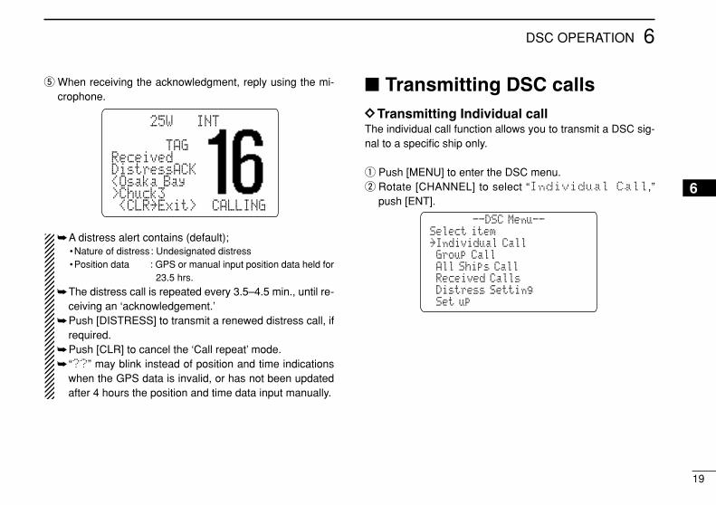
t When receiving the acknowledgment, reply using the mi-crophone.
A distress alert contains (default);•Nature of distress: Undesignated distress•Position data : GPS or manual input position data held for
23.5 hrs.
The distress call is repeated every 3.5–4.5 min., until re-ceiving an ‘acknowledgement.’
Push [DISTRESS] to transmit a renewed distress call, ifrequired.
Push [CLR] to cancel the ‘Call repeat’ mode. “??” may blink instead of position and time indications
when the GPS data is invalid, or has not been updatedafter 4 hours the position and time data input manually.
Transmitting DSC callsDDTransmitting Individual callThe individual call function allows you to transmit a DSC sig-nal to a specific ship only.
q Push [MENU] to enter the DSC menu.w Rotate [CHANNEL] to select “Individual Call,”
push [ENT].
Select item--DSC Menu--
˘Set up
˘Individual Call
˘All Ships Call
˘Distress Setting˘Received Calls
˘Group Call
BUSY-25W---INT---CALLLOCAL--DUPSCRAM--TAGReceivedCANDistressACK<Osaka Bay>Chuck3-<CLR˘Exit>--CALLING
6
20
6 DSC OPERATION
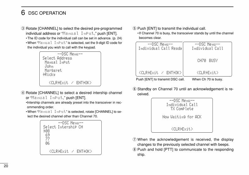
e Rotate [CHANNEL] to select the desired pre-programmedindividual address or “Manual Input,” push [ENT].•The ID code for the individual call can be set in advance. (p. 24)•When “Manual Input” is selected, set the 9-digit ID code forthe individual you wish to call with the keypad.
r Rotate [CHANNEL] to select a desired intership channelor “Manual Input,” push [ENT].•Intership channels are already preset into the transceiver in rec-ommending order.
•When “Manual Input” is selected, rotate [CHANNEL] to se-lect the desired channel other than Channel 70.
t Push [ENT] to transmit the individual call.• If Channel 70 is busy, the transceiver stands by until the channelbecomes clear.
y Standby on Channel 70 until an acknowledgement is re-ceived.
u When the acknowledgement is received, the displaychanges to the previously selected channel with beeps.
i Push and hold [PTT] to communicate to the respondingship.
Individual Call
<CLR˘Exit>
TX Complete
Now Waiting for ACK
--DSC Menu--
˘˘Ricky
˘Icom
Individual Call Ready
<CLR˘Exit / ENT˘OK>
--DSC Menu--Individual Call
CH70 BUSY
<CLR˘Exit>
--DSC Menu--
Push [ENT] to transmit DSC call. When Ch 70 is busy.
Select Intership CH
<CLR˘Exit / ENT˘OK>
˘08
˘77
--DSC Menu--
˘˘06
˘69
Select Address
<CLR˘Exit / ENT˘OK>
˘Manual Input
˘Margaret
--DSC Menu--
˘Ricky
˘John
21
6DSC OPERATION
6
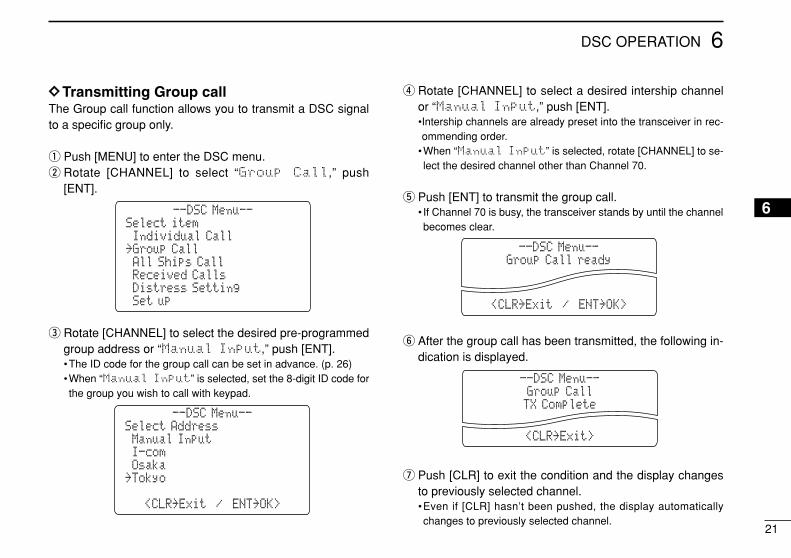
DDTransmitting Group callThe Group call function allows you to transmit a DSC signalto a specific group only.
q Push [MENU] to enter the DSC menu.w Rotate [CHANNEL] to select “Group Call,” push
[ENT].
e Rotate [CHANNEL] to select the desired pre-programmedgroup address or “Manual Input,” push [ENT].•The ID code for the group call can be set in advance. (p. 26)•When “Manual Input” is selected, set the 8-digit ID code forthe group you wish to call with keypad.
r Rotate [CHANNEL] to select a desired intership channelor “Manual Input,” push [ENT].•Intership channels are already preset into the transceiver in rec-ommending order.
•When “Manual Input” is selected, rotate [CHANNEL] to se-lect the desired channel other than Channel 70.
t Push [ENT] to transmit the group call.• If Channel 70 is busy, the transceiver stands by until the channelbecomes clear.
y After the group call has been transmitted, the following in-dication is displayed.
u Push [CLR] to exit the condition and the display changesto previously selected channel.•Even if [CLR] hasn’t been pushed, the display automaticallychanges to previously selected channel.
Group CallTX Complete
<CLR˘Exit>
--DSC Menu--
Group Call ready
<CLR˘Exit / ENT˘OK>
--DSC Menu--
Select Address
<CLR˘Exit / ENT˘OK>
˘Manual Input
˘Osaka
--DSC Menu--
˘˘Tokyo
˘I-com
Select item
˘Set up
˘Individual Call
˘All Ships Call
--DSC Menu--
˘Distress Setting˘Received Calls
˘Group Call
22
6 DSC OPERATION
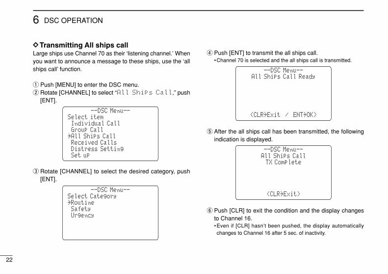
DDTransmitting All ships callLarge ships use Channel 70 as their ‘listening channel.’ Whenyou want to announce a message to these ships, use the ‘allships call’ function.
q Push [MENU] to enter the DSC menu.w Rotate [CHANNEL] to select “All Ships Call,” push
[ENT].
e Rotate [CHANNEL] to select the desired category, push[ENT].
r Push [ENT] to transmit the all ships call.•Channel 70 is selected and the all ships call is transmitted.
t After the all ships call has been transmitted, the followingindication is displayed.
y Push [CLR] to exit the condition and the display changesto Channel 16.•Even if [CLR] hasn’t been pushed, the display automaticallychanges to Channel 16 after 5 sec. of inactivity.
All Ships CallTX Complete
<CLR˘Exit>
--DSC Menu--
All Ships Call Ready
<CLR˘Exit / ENT˘OK>
--DSC Menu--
Select Category
˘Received Calls
˘Routine
˘Urgency
--DSC Menu--
˘Polling Request˘Position Request
˘Safety
Select item˘Individual Call
˘All Ships Call
--DSC Menu--
˘Group Call
˘Set up˘Distress Setting˘Received Calls
23
6DSC OPERATION
6
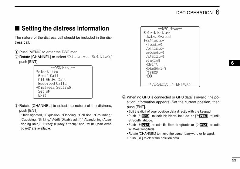
Setting the distress informationThe nature of the distress call should be included in the dis-tress call.
q Push [MENU] to enter the DSC menu.w Rotate [CHANNEL] to select “Distress Setting,”
push [ENT].
e Rotate [CHANNEL] to select the nature of the distress,push [ENT].• ‘Undesignated,’ ‘Explosion,’ ‘Flooding,’ ‘Collision,’ ‘Grounding,’‘Capsizing,’ ‘Sinking,’ ‘Adrift (Disable adrift),’ ‘Abandoning (Aban-doning ship),’ ‘Piracy (Piracy attack),’ and ‘MOB (Man over-board)’ are available.
r When no GPS is connected or GPS data is invalid, the po-sition information appears. Set the current position, thenpush [ENT].•Edit the digit of your position data directly with the keypad.•Push [6• ] to edit N; North latitude or [7• ] to edit S; South latitude.
•Push [3• ] to edit E; East longitude or [9• ] to edit W; West longitude.
•Rotate [CHANNEL] to move the cursor backward or forward.•Push [CE] to clear the position data.
WXYDEF
PRSMNO
Select Nature˘Undesignated
˘Flooding
--DSC Menu--
˘
˘Collision˘Grounding
˘Abandoning
˘Capsizing˘Sinking˘Adrift
<CLR˘Exit / ENT˘OK>
˘Piracy
˘EPIRB˘MOB
˘Explosion
Select item
˘Exit
˘Group Call
˘Received Calls
--DSC Menu--
˘Set up˘Distress Setting
˘All Ships Call
24
6 DSC OPERATION
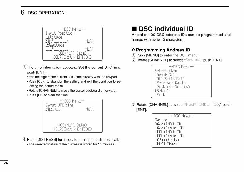
t The time information appears. Set the current UTC time,push [ENT].•Edit the digit of the current UTC time directly with the keypad.•Push [CLR] to abandon the setting and exit the condition to se-lecting the nature menu.
•Rotate [CHANNEL] to move the cursor backward or forward.•Push [CE] to clear the time.
y Push [DISTRESS] for 5 sec. to transmit the distress call.•The selected nature of the distress is stored for 10 minutes.
DSC individual IDA total of 100 DSC address IDs can be programmed andnamed with up to 10 characters.
DDProgramming Address IDq Push [MENU] to enter the DSC menu.w Rotate [CHANNEL] to select “Set up,” push [ENT].
e Rotate [CHANNEL] to select “Add: INDV ID,” push[ENT].
Set up
˘MMSI Check
˘Add:INDV ID
˘DEL:INDV ID
--DSC Menu--
˘Offset time˘DEL:Group ID
˘Add:Group ID
Select item
˘Exit
˘Received Calls
--DSC Menu--
˘Set up˘Distress Setting
˘Group Call˘All Ships Call
Input UTC time˘K__:__˘˘˘˘˘˘˘˘˘˘˘˘Null
--DSC Menu--
<CE˘Null Data><CLR˘Exit / ENT˘OK>
Input PositionLatitude
Longitude
--DSC Menu--
<CE˘Null Data>___°__.___W˘˘˘˘˘˘˘˘Null
˘K_°__.___N˘˘˘˘˘˘˘˘Null
<CLR˘Exit / ENT˘OK>
25
6DSC OPERATION
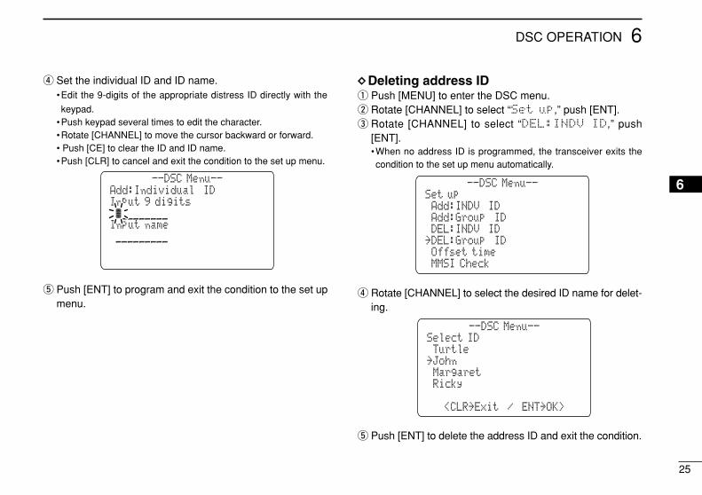
6
r Set the individual ID and ID name.•Edit the 9-digits of the appropriate distress ID directly with the
keypad.•Push keypad several times to edit the character.•Rotate [CHANNEL] to move the cursor backward or forward.• Push [CE] to clear the ID and ID name.•Push [CLR] to cancel and exit the condition to the set up menu.
t Push [ENT] to program and exit the condition to the set upmenu.
DDDeleting address IDq Push [MENU] to enter the DSC menu.w Rotate [CHANNEL] to select “Set up,” push [ENT].e Rotate [CHANNEL] to select “DEL:INDV ID,” push
[ENT].•When no address ID is programmed, the transceiver exits thecondition to the set up menu automatically.
r Rotate [CHANNEL] to select the desired ID name for delet-ing.
t Push [ENT] to delete the address ID and exit the condition.
Select ID
<CLR˘Exit / ENT˘OK>
˘Turtle
˘Margaret
--DSC Menu--
˘˘Ricky
˘John
Set up
˘MMSI Check
˘Add:INDV ID
˘DEL:INDV ID
--DSC Menu--
˘Offset time˘DEL:Group ID
˘Add:Group ID
Add:Individual IDInput 9 digits
Input name
--DSC Menu--
˘__________________
˘ä________________
26
6 DSC OPERATION
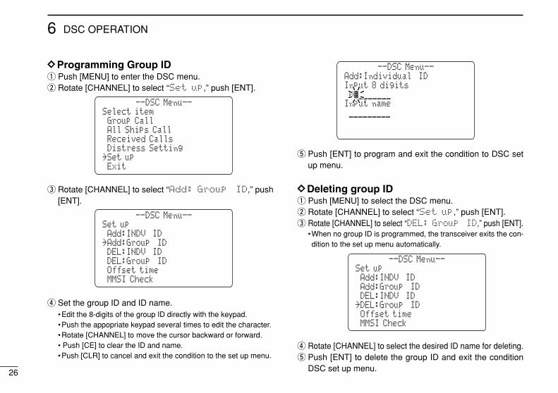
DDProgramming Group IDq Push [MENU] to enter the DSC menu.w Rotate [CHANNEL] to select “Set up,” push [ENT].
e Rotate [CHANNEL] to select “Add: Group ID,” push[ENT].
r Set the group ID and ID name.•Edit the 8-digits of the group ID directly with the keypad.•Push the appopriate keypad several times to edit the character.•Rotate [CHANNEL] to move the cursor backward or forward.• Push [CE] to clear the ID and name.•Push [CLR] to cancel and exit the condition to the set up menu.
t Push [ENT] to program and exit the condition to DSC setup menu.
DDDeleting group IDq Push [MENU] to select the DSC menu.w Rotate [CHANNEL] to select “Set up,” push [ENT].e Rotate [CHANNEL] to select “DEL: Group ID,” push [ENT].
•When no group ID is programmed, the transceiver exits the con-dition to the set up menu automatically.
r Rotate [CHANNEL] to select the desired ID name for deleting.t Push [ENT] to delete the group ID and exit the condition
DSC set up menu.
Set up
˘MMSI Check
˘Add:INDV ID
˘DEL:INDV ID
--DSC Menu--
˘Offset time˘DEL:Group ID
˘Add:Group ID
Add:Individual IDInput 8 digits
Input name
--DSC Menu--
˘__________________
˘0ä______________
Set up
˘MMSI Check
˘Add:INDV ID
˘DEL:INDV ID
--DSC Menu--
˘Offset time˘DEL:Group ID
˘Add:Group ID
Select item
˘Exit
˘Received Calls
--DSC Menu--
˘Set up˘Distress Setting
˘Group Call˘All Ships Call

27
6DSC OPERATION
6
Receiving DSC callsDDReceiving a distress callWhile monitoring Channel 70 and a distress call is received:The emergency alarm sounds for 2 minutes.
•Push any switch to stop the alarm.
“Received Distress” appears in the display, thenChannel 16 is automatically selected.
Continue monitoring Channel 16 as a coast station may re-quire assistance.
DDReceiving a distress acknowledgementWhile monitoring Channel 70 and a distress acknowledge-ment to other ship is received:The emergency alarm sounds for 2 minutes.
•Push any switch to stop the alarm.
“Received Distress ACK” appears in the display,then Channel 16 is automatically selected.
DDReceiving an all ships callWhile monitoring Channel 70 and an all ships call is received:The emergency alarm sounds when the category is ‘Dis-
tress’ or ‘Urgency’; 3 beeps sound for other categories. “Received All Ships” appears in the display, then
Channel 16 is automatically selected for voice communica-tion.
Monitor channel 16 for an announcement from the callingvessel.
BUSY-25W---INT---CALLLOCAL--DUPSCRAM--TAGReceivedCANAll Ships<Chuck3><CLR˘Exit>-<CLR˘OK> --CALLING
BUSY-25W---INT---CALLLOCAL--DUPSCRAM--TAGReceivedCANDistressACK<Osaka Bay>Chuck3-<CLR˘Exit>--CALLING
BUSY-25W---INT---CALLLOCAL--DUPSCRAM--TAGReceivedCANDistress<Chuck3
-<CLR˘Exit>--CALLING
28
6 DSC OPERATION
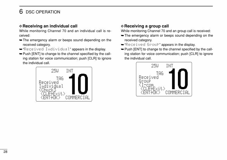
DDReceiving an individual callWhile monitoring Channel 70 and an individual call is re-ceived:The emergency alarm or beeps sound depending on the
received category. “Received Individual” appears in the display.Push [ENT] to change to the channel specified by the call-
ing station for voice communication; push [CLR] to ignorethe individual call.
DDReceiving a group callWhile monitoring Channel 70 and an group call is received:The emergency alarm or beeps sound depending on the
received category. “Received Group” appears in the display.Push [ENT] to change to the channel specified by the call-
ing station for voice communication; push [CLR] to ignorethe individual call.
BUSY-25W---INT---CALLLOCAL--DUPSCRAM--TAGReceivedCANGroup<I-com <CLR˘Exit> <ENT˘OK> COMMERCIAL
BUSY-25W---INT---CALLLOCAL--DUPSCRAM--TAGReceivedCANIndividual<Chuck3 <CLR˘Exit> <ENT˘OK> COMMERCIAL
29
6DSC OPERATION
6
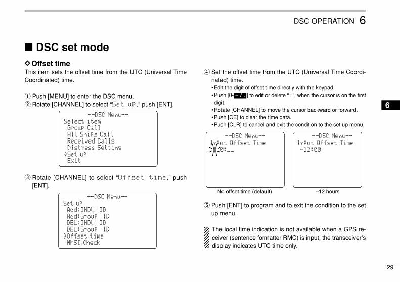
DSC set modeDDOffset timeThis item sets the offset time from the UTC (Universal TimeCoordinated) time.
q Push [MENU] to enter the DSC menu.w Rotate [CHANNEL] to select “Set up,” push [ENT].
e Rotate [CHANNEL] to select “Offset time,” push[ENT].
r Set the offset time from the UTC (Universal Time Coordi-nated) time.•Edit the digit of offset time directly with the keypad.•Push [0• ] to edit or delete “-”, when the cursor is on the firstdigit.
•Rotate [CHANNEL] to move the cursor backward or forward.•Push [CE] to clear the time data.•Push [CLR] to cancel and exit the condition to the set up menu.
t Push [ENT] to program and to exit the condition to the setup menu.
The local time indication is not available when a GPS re-ceiver (sentence formatter RMC) is input, the transceiver’sdisplay indicates UTC time only.
Input Offset Time--DSC Menu--
No offset time (default) –12 hours
K_0:__Input Offset Time
--DSC Menu--
-12:00
– / .
Set up
˘MMSI Check
˘Add:INDV ID
˘DEL:INDV ID
--DSC Menu--
˘Offset time˘DEL:Group ID
˘Add:Group ID
Select item
˘Exit
˘Received Calls
--DSC Menu--
˘Set up˘Distress Setting
˘Group Call˘All Ships Call
30
6 DSC OPERATION
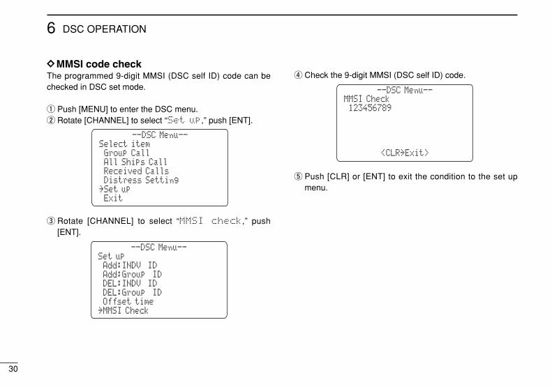
DDMMSI code checkThe programmed 9-digit MMSI (DSC self ID) code can bechecked in DSC set mode.
q Push [MENU] to enter the DSC menu.w Rotate [CHANNEL] to select “Set up,” push [ENT].
e Rotate [CHANNEL] to select “MMSI check,” push[ENT].
r Check the 9-digit MMSI (DSC self ID) code.
t Push [CLR] or [ENT] to exit the condition to the set upmenu.
MMSI Check˘123456789
--DSC Menu--
<CLR˘Exit>
Set up
˘MMSI Check
˘Add:INDV ID
˘DEL:INDV ID
--DSC Menu--
˘Offset time˘DEL:Group ID
˘Add:Group ID
Select item
˘Exit
˘Received Calls
--DSC Menu--
˘Set up˘Distress Setting
˘Group Call˘All Ships Call
31
6DSC OPERATION
6
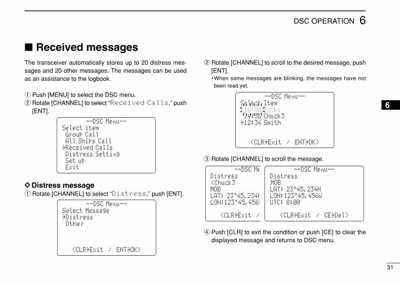
Received messagesThe transceiver automatically stores up to 20 distress mes-sages and 20 other messages. The messages can be usedas an assistance to the logbook.
q Push [MENU] to select the DSC menu.w Rotate [CHANNEL] to select “Received Calls,” push
[ENT].
DDDistress messageq Rotate [CHANNEL] to select “Distress,” push [ENT].
w Rotate [CHANNEL] to scroll to the desired message, push[ENT].•When some messages are blinking, the messages have notbeen read yet.
e Rotate [CHANNEL] to scroll the message.
r Push [CLR] to exit the condition or push [CE] to clear thedisplayed message and returns to DSC menu.
Distress<Chuck3
LAT: 23"45.234N
--DSC Menu--
LON:123"45.456W
MOB
<CLR˘Exit / CE˘Del>
Distress--DSC Menu--
UTC: 8:00
LAT: 23"45.234NLON:123"45.456W
MOB
<CLR˘Exit / CE˘Del>
--DSC Menu--
<CLR˘Exit / ENT˘OK>
Select Item˘16:00 Ricky˘14:56 Chuck3˘12:34 Smith
--DSC Menu--
<CLR˘Exit / ENT˘OK>
Select Message˘Distress˘Other
Select item
˘Exit
˘Received Calls
--DSC Menu--
˘Set up˘Distress Setting
˘Group Call˘All Ships Call

32
6 DSC OPERATION
DDOther messagesq Rotate [CHANNEL] to select “Other,” push [ENT].
w Rotate [CHANNEL] to scroll to the desired message, push[ENT].•When some messages are blinking, the messages have notbeen read yet.
e Rotate [CHANNEL] to scroll the message.•The stored message has various information and depending onthe type of distress call.
r Push [CLR] to exit the condition or push [CE] to clear thedisplayed message and returns to DSC menu.
Group Call<Chuck3
>OSAKA-1
--DSC Menu--
F3E simplex
Routine
<CLR˘Exit / CE˘Del>
Group Call--DSC Menu--
CH10
>OSAKA-1F3E simplex
Routine
<CLR˘Exit / CE˘Del>
--DSC Menu--
<CLR˘Exit / ENT˘OK>
Select Message˘Individual Call˘All Ships Call˘Group Call˘Individual Call
--DSC Menu--
<CLR˘Exit / ENT˘OK>
Select Message˘Distress˘Other
33
7OTHER FUNCTIONS
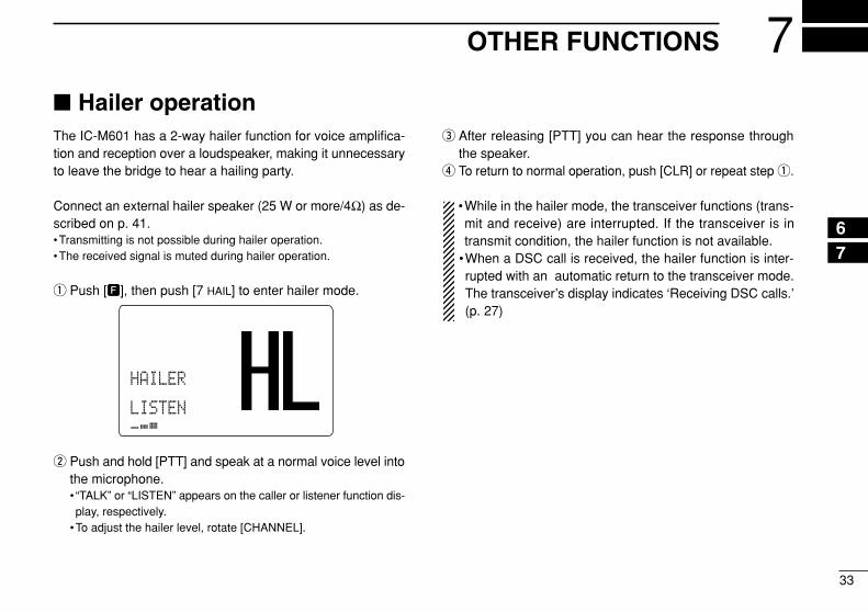
Hailer operationThe IC-M601 has a 2-way hailer function for voice amplifica-tion and reception over a loudspeaker, making it unnecessaryto leave the bridge to hear a hailing party.
Connect an external hailer speaker (25 W or more/4Ω) as de-scribed on p. 41.•Transmitting is not possible during hailer operation.•The received signal is muted during hailer operation.
q Push [F], then push [7 HAIL] to enter hailer mode.
w Push and hold [PTT] and speak at a normal voice level intothe microphone.• “TALK” or “LISTEN” appears on the caller or listener function dis-play, respectively.
•To adjust the hailer level, rotate [CHANNEL].
e After releasing [PTT] you can hear the response throughthe speaker.
r To return to normal operation, push [CLR] or repeat step q.
•While in the hailer mode, the transceiver functions (trans-mit and receive) are interrupted. If the transceiver is intransmit condition, the hailer function is not available.
•When a DSC call is received, the hailer function is inter-rupted with an automatic return to the transceiver mode.The transceiver’s display indicates ‘Receiving DSC calls.’(p. 27)
BUSY-25W---INT---CALLLOCAL--DUPSCRAM--TAGNORMAL-SCANHAILER-34"34.506NLISTEN.236W___cal--1:10--CALLING____
76
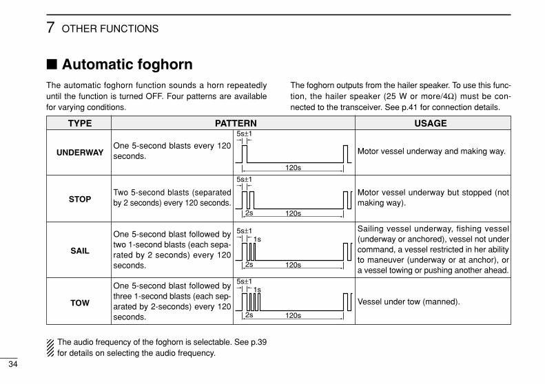
Automatic foghornThe automatic foghorn function sounds a horn repeatedlyuntil the function is turned OFF. Four patterns are availablefor varying conditions.
The foghorn outputs from the hailer speaker. To use this func-tion, the hailer speaker (25 W or more/4Ω) must be con-nected to the transceiver. See p.41 for connection details.
TYPE PATTERN USAGE
UNDERWAY
STOP
SAIL
TOW
34
7 OTHER FUNCTIONS
The audio frequency of the foghorn is selectable. See p.39for details on selecting the audio frequency.
One 5-second blasts every 120seconds.
Two 5-second blasts (separatedby 2 seconds) every 120 seconds.
One 5-second blast followed bytwo 1-second blasts (each sepa-rated by 2 seconds) every 120seconds.
One 5-second blast followed bythree 1-second blasts (each sep-arated by 2-seconds) every 120seconds.
Motor vessel underway and making way.
Motor vessel underway but stopped (notmaking way).
Sailing vessel underway, fishing vessel(underway or anchored), vessel not undercommand, a vessel restricted in her abilityto maneuver (underway or at anchor), ora vessel towing or pushing another ahead.
Vessel under tow (manned).
5s±1
120s
5s±1
2s
1s
120s
5s±1
2s
1s
120s
5s±1
2s 120s
35
7OTHER FUNCTIONS
q Push [F], then push [8 FOG] to enter automatic foghornmode.
w Rotate [CHANNEL] to select the desired foghorn pattern,push [ENT].• ‘UNDERWAY,’ ‘STOP,’ ‘SAIL,’ ‘TOW’ are available. (p.34)•Even if [ENT] hasn’t been pushed, the display automaticallychanges to the next step after 5 sec. of inactivity.
e Rotate [CHANNEL] to adjust the foghorn level, push[ENT].•The foghorn level is adjustable in 7 steps.•Even if [ENT] hasn’t been pushed, the display automaticallychanges to the next step after 5 sec. of inactivity.
r To return to normal operation, repeat step q.
When a DSC call is received, the automatic foghorn func-tion is interrupted with an automatic return to the trans-ceiver mode. The transceiver’s display indicates ‘Receiving DSC calls.’ (p 27)
Microphone lock functionThe microphone lock function electrically locks the [Y]/[Z]and [16/C] switches on the supplied microphone. This pre-vents accidental channel changes and accidental function ac-cess.
While pushing [16/C] on the HM-137, turn power ON to tog-gle the lock function ON or OFF.
BUSY-25W---INT---CALLLOCAL--DUPSCRAM--TAGReceivedCANFOG HORNOUTPUTUNDERWAYE<ENT˘OK> COMMERCIAL_______
BUSY-25W---INT---CALLLOCAL--DUPSCRAM--TAGReceivedCANFOG HORNOUTPUT <CLR˘Exit>E<ENT˘OK> COMMERCIAL_______
BUSY-25W---INT---CALLLOCAL--DUPSCRAM--TAGReceivedCAN˘UNDERWAY<STOP <CLR˘Exit> <ENT˘OK> COMMERCIAL
7
36
7 OTHER FUNCTIONS
Intercom operationThe optional intercom function allows you to talk with a dis-tance place such as the deck from the cabin. The optionalHM-134 REMOTE-CONTROL MICROPHONE is required for in-tercom operation.
Connect an optional HM-134 as described on p. 61.•Transmitting is impossible during intercom operation.•The received signal is muted during intercom operation.
q Push [F], then push [9 IC] to enter intercom mode.•The HM-134 power is automatically turned ON, even if the poweris OFF.
w Push and hold [9 IC] again to call up.•The transceiver and microphone emit call beeps.
e Push and hold [PTT] and speak at a normal voice level intothe microphone.• “TALK” or “LISTEN” appears on the caller or listener function dis-play, respectively.
•To adjust the IC-M601’s speaker output level, rotate [VOL].•To adjust the HM-134’s speaker output level, push [Y]/[Z] afterpushing [VOL].
r After releasing [PTT] you can hear the response throughthe speaker.
t To return to normal operation, push [CLR] or repeat step q.
•While in the intercom mode, the transceiver functions(transmit and receive) are interrupted. If the transceiver isin transmit condition, the intercom function is not avail-able.
•When a DSC call is received, the intercom function is in-terrupted with an automatic return to the transceivermode. The transceiver’s display indicates ‘Receiving DSCcalls.’ (p 27)
INT
BUSY-25W---INT---CALLLOCAL--DUPSCRAM--TAGNORMAL-SCANINTERCOM-34"34.206NTALK123"23.236W--UTC-10:10COMMERCIAL
IC-M601 (caller) HM-134 (listener)
INT
BUSY-25W---INT---CALLLOCAL--DUPSCRAM--TAGNORMAL-SCANINTERCOM-34"34.206N123"23.236W--UTC-10:10COMMERCIAL
IC-M601 HM-134
37
8SET MODE
87
Beep tone
Beep
Scan type
Scan type
Scan resume timer
Scan timer
Dual/tri-watch of COMMANDMIC
Dual/Tri COMMANDMIC
LCD contrast
Contrast
Rotate [CHANNEL] Push when using HM-134
˘Scan Type˘Scan Timer
˘Beep
--Set Mode--
˘Contrast˘Internal Speaker
˘Dual/Tri COMMANDMIC
˘Foghorn Frequency˘Exit
Foghorn FrequencyFoghorn Frequency and Internal Speaker items are not selectable when using HM-134.
Set mode programmingSet mode is used to change the conditions of the trans-ceiver’s functions: scan type (normal or priority), scan resumetimer, dual/tri-watch of COMMANDMIC, transceiver’s beeptone, internal speaker, LCD contrast and automatic foghornfrequency.
Available functions may differ depending on dealer setting.
q Turn power OFF.w While pushing [16•C], turn power ON to enter set mode.e After the display appears, release [16•C].r Rotate [CHANNEL] to select the desired item, push [ENT].
Or push [16•C] to select the item when using an optionalHM-134.
t Rotate [CHANNEL] to select the desired condition of theitem. Use [Y]/[Z] when using an optional HM-134.
y Rotate [CHANNEL] to select “Exit,” push [ENT] to exitset mode and returns to normal operation condition
•SET MODE CONSTRUCTION
Set mode itemsDDScan typeThe transceiver has 2 scan types: normal scan and priorityscan. Normal scan searches all tag channels in the selectedchannel group. Priority scan searches all tag channels in se-quence while monitoring Channel 16.
DDScan resume timerThe scan resume timer can be selected as a pause (OFF) ortimer scan (ON). When OFF is selected, the scan pausesuntil the signal disappears. When ON is selected, the scanpauses 5 sec. and resumes even if a signal has been re-ceived on channels except for Channel 16.
DDDual/Tri-watch of COMMANDMIC(Appears when connecting HM-134)
This item sets the HM-134’s [DUAL•IC] switch function asdual watch or tri-watch.
DDBeep toneYou can select silent operation by turning beep tones OFF, oryou can have confirmation beeps sound at the push of aswitch by turning beep tones ON.
The optional HM-134 has it’s own setting for the beep tone.
Beep˘ON
˘OFF
--Set Mode--
˘Polling Request˘Position Request
˘OFF
˘<ENT˘OK>
(Default: ON)
Dual/Tri COMMANDMIC˘Tri-watch
˘OFF
--Set Mode--
˘Polling Request˘Position Request
˘Dualwatch
˘<ENT˘OK>
(Default: Dualwatch)
Scan Timer˘ON
˘All Ships Call
--Set Mode--
˘Polling Request˘Position Request
˘OFF
<ENT˘OK>
(Default: OFF)
Scan Type˘Priority
˘All Ships Call
--Set Mode--
˘Polling Request˘Position Request
˘Normal
<ENT˘OK>
(Default: Normal)
38
8 SET MODE
8SET MODE
39
8
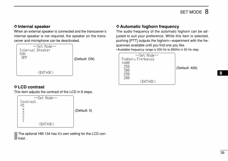
DD Internal speakerWhen an external speaker is connected and the transceiver’sinternal speaker is not required, the speaker on the trans-ceiver and microphone can be deactivated.
DDLCD contrastThis item adjusts the contrast of the LCD in 8 steps.
The optional HM-134 has it’s own setting for the LCD con-trast.
DDAutomatic foghorn frequencyThe audio frequency of the automatic foghorn can be ad-justed to suit your preference. While this item is selected,pushing [PTT] outputs the foghorn—experiment with the fre-quencies available until you find one you like.•Available frequency range is 200 Hz to 850Hz in 50 Hz step.
Foghorn Frequency˘400
˘300
--Set Mode--
˘200˘250
˘350
˘<ENT˘OK>
(Default: 400)
Contrast˘5
˘3
--Set Mode--
˘1˘2
˘4
˘<ENT˘OK>
(Default: 5)
Internal Speaker˘ON
˘OFF
--Set Mode--
˘Polling Request˘Position Request
˘OFF
˘<ENT˘OK>
(Default: ON)
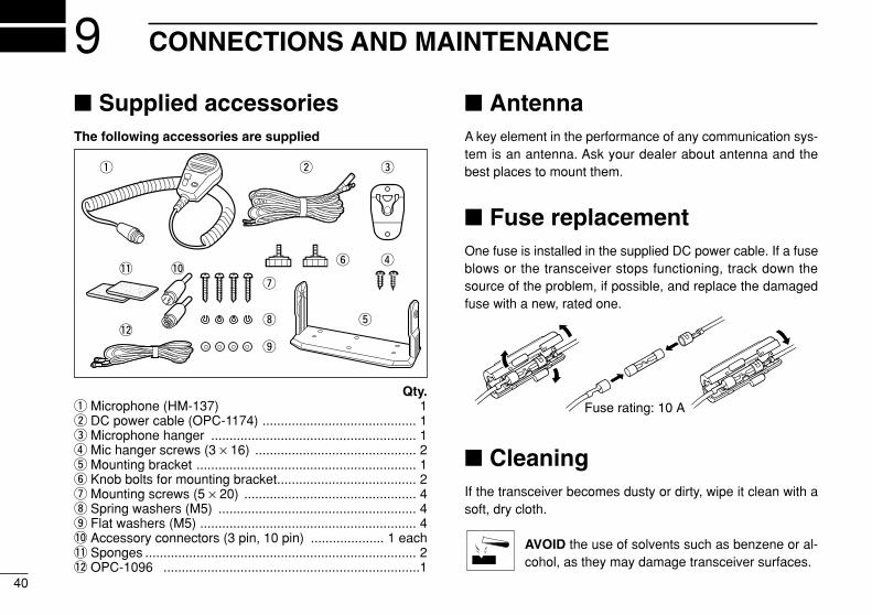
Supplied accessoriesThe following accessories are supplied
Qty.q Microphone (HM-137) 1w DC power cable (OPC-1174) .......................................... 1e Microphone hanger ........................................................ 1r Mic hanger screws (3 × 16) ............................................ 2t Mounting bracket ............................................................ 1y Knob bolts for mounting bracket...................................... 2u Mounting screws (5 × 20) ............................................... 4i Spring washers (M5) ...................................................... 4o Flat washers (M5) ........................................................... 4!0 Accessory connectors (3 pin, 10 pin) .................... 1 each!1 Sponges .......................................................................... 2!2 OPC-1096 ......................................................................1
AntennaA key element in the performance of any communication sys-tem is an antenna. Ask your dealer about antenna and thebest places to mount them.
Fuse replacementOne fuse is installed in the supplied DC power cable. If a fuseblows or the transceiver stops functioning, track down thesource of the problem, if possible, and replace the damagedfuse with a new, rated one.
CleaningIf the transceiver becomes dusty or dirty, wipe it clean with asoft, dry cloth.
AVOID the use of solvents such as benzene or al-cohol, as they may damage transceiver surfaces.
Fuse rating: 10 A
q w e
r
t
y
u!1 !0
!2i
o
40
9 CONNECTIONS AND MAINTENANCE
41
9CONNECTIONS AND MAINTENANCE
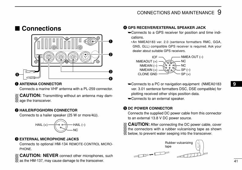
Connections
q ANTENNA CONNECTORConnects a marine VHF antenna with a PL-259 connector.
CAUTION: Transmitting without an antenna may dam-age the transceiver.
w HAILER/FOGHORN CONNECTORConnects to a hailer speaker (25 W or more/4Ω).
e EXTERNAL MICROPHONE JACKSConnects to optional HM-134 REMOTE-CONTROL MICRO-
PHONE.
CAUTION: NEVER connect other microphones, suchas the HM-137, may cause damage to the transceiver.
r GPS RECEIVER/EXTERNAL SPEAKER JACKConnects to a GPS receiver for position and time indi-
cations.•An NMEA0183 ver. 2.0 (sentence formatters RMC, GGA,GNS, GLL) compatible GPS receiver is required. Ask yourdealer about suitable GPS receivers.
Connects to a PC or navigation equipment (NMEA0183ver. 3.01 sentence formatters DSC, DSE compatible) forplotting received other ships position data.
Connects to an external speaker.
t DC POWER CONNECTORConnects the supplied DC power cable from this connectorto an external 13.8 V DC power source.
CAUTION: After connecting the DC power cable, coverthe connectors with a rubber vulcanising tape as shownbelow, to prevent water seeping into the transceiver.
NMEAOUT (+)NMEAIN (–)
SP (–)CLONE GND SP (+)NMEAIN (+)
NMEA OUT (–)ICFNCNC
HAIL (+) HAIL (–)
NC
t
q
e
r
w
Rubber vulcanizingtape
9
42
9 CONNECTIONS AND MAINTENANCE
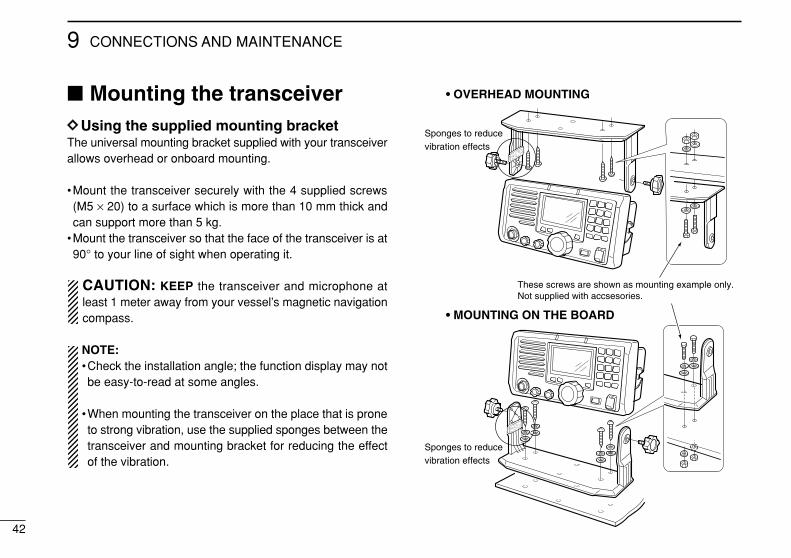
Mounting the transceiverDDUsing the supplied mounting bracketThe universal mounting bracket supplied with your transceiverallows overhead or onboard mounting.
•Mount the transceiver securely with the 4 supplied screws(M5 × 20) to a surface which is more than 10 mm thick andcan support more than 5 kg.
•Mount the transceiver so that the face of the transceiver is at90° to your line of sight when operating it.
CAUTION: KEEP the transceiver and microphone atleast 1 meter away from your vessel’s magnetic navigationcompass.
NOTE:•Check the installation angle; the function display may notbe easy-to-read at some angles.
•When mounting the transceiver on the place that is proneto strong vibration, use the supplied sponges between thetransceiver and mounting bracket for reducing the effectof the vibration.
These screws are shown as mounting example only. Not supplied with accsesories.
• OVERHEAD MOUNTING
• MOUNTING ON THE BOARD
Sponges to reduce vibration effects
Sponges to reduce vibration effects
43
9CONNECTIONS AND MAINTENANCE
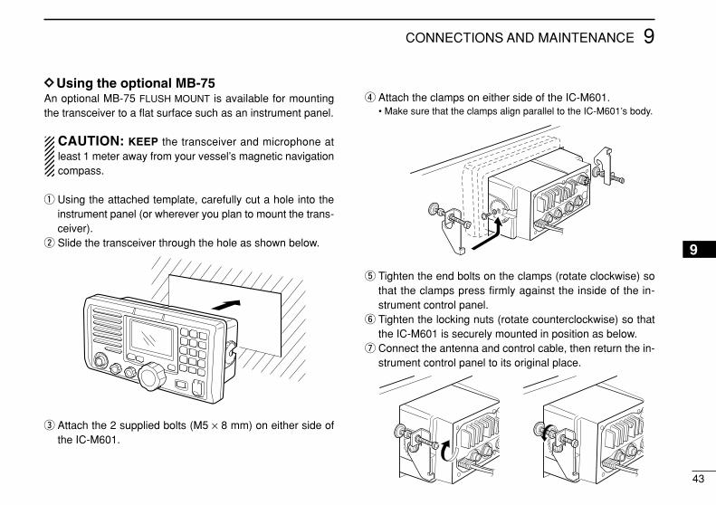
DDUsing the optional MB-75An optional MB-75 FLUSH MOUNT is available for mountingthe transceiver to a flat surface such as an instrument panel.
CAUTION: KEEP the transceiver and microphone atleast 1 meter away from your vessel’s magnetic navigationcompass.
q Using the attached template, carefully cut a hole into theinstrument panel (or wherever you plan to mount the trans-ceiver).
w Slide the transceiver through the hole as shown below.
e Attach the 2 supplied bolts (M5 × 8 mm) on either side ofthe IC-M601.
r Attach the clamps on either side of the IC-M601.• Make sure that the clamps align parallel to the IC-M601’s body.
t Tighten the end bolts on the clamps (rotate clockwise) sothat the clamps press firmly against the inside of the in-strument control panel.
y Tighten the locking nuts (rotate counterclockwise) so thatthe IC-M601 is securely mounted in position as below.
u Connect the antenna and control cable, then return the in-strument control panel to its original place.
9
44
9 CONNECTIONS AND MAINTENANCE
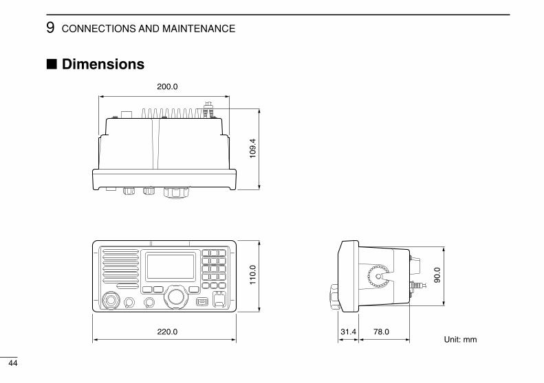
Dimensions
220.0 31.4 78.0
110.
010
9.4
200.0
Unit: mm
90.0
45
10TROUBLESHOOTING
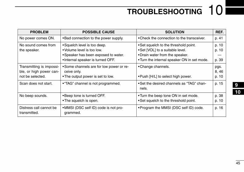
PROBLEM POSSIBLE CAUSE SOLUTION REF.
No power comes ON. •Bad connection to the power supply. •Check the connection to the transceiver. p. 41
No sound comes fromthe speaker.
•Squelch level is too deep.•Volume level is too low.•Speaker has been exposed to water.• Internal speaker is turned OFF.
•Set squelch to the threshold point.•Set [VOL] to a suitable level.•Drain water from the speaker.•Turn the internal speaker ON in set mode.
p. 10p. 10
—p. 39
Transmitting is impossi-ble, or high power can-not be selected.
•Some channels are for low power or re-ceive only.
•The output power is set to low.
•Change channels.
•Push [H/L] to select high power.
pgs.8, 46p. 10
Scan does not start. • “TAG” channel is not programmed. •Set the desired channels as “TAG” chan-nels.
p. 15
No beep sounds. •Beep tone is turned OFF.•The squelch is open.
•Turn the beep tone ON in set mode.•Set squelch to the threshold point.
p. 38p. 10
Distress call cannot betransmitted.
•MMSI (DSC self ID) code is not pro-grammed.
•Program the MMSI (DSC self ID) code. p. 16
910
46
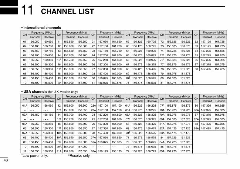
11 CHANNEL LIST
• International channels
CHFrequency (MHz)
CHFrequency (MHz)
CHFrequency (MHz)
CHFrequency (MHz)
CHFrequency (MHz)
CHFrequency (MHz)
Transmit Receive Transmit Receive Transmit Receive Transmit Receive Transmit Receive Transmit Receive
01 156.050 160.650 11 156.550 156.550 21 157.050 161.650 62 156.125 160.725 72 156.625 156.625 82 157.125 161.725
02 156.100 160.700 12 156.600 156.600 22 157.100 161.700 63 156.175 160.775 73 156.675 156.675 83 157.175 161.775
03 156.150 160.750 13 156.650 156.650 23 157.150 161.750 64 156.225 160.825 74 156.725 156.725 84 157.225 161.825
04 156.200 160.800 14 156.700 156.700 24 157.200 161.800 65 156.275 160.875 75† 156.775 156.775 85 157.275 161.875
05 156.250 160.850 15† 156.750 156.750 25 157.250 161.850 66 156.325 160.925 76† 156.825 156.825 86 157.325 161.925
06 156.300 156.300 16 156.800 156.800 26 157.300 161.900 67 156.375 156.375 77 156.875 156.875 87 157.375 157.375
07 156.350 160.950 17† 156.850 156.850 27 157.350 161.950 68 156.425 156.425 78 156.925 161.525 88 157.425 157.425
08 156.400 156.400 18 156.900 161.500 28 157.400 162.000 69 156.475 156.475 79 156.975 161.575
09 156.450 156.450 19 156.950 161.550 60 156.025 160.625 70‡ 156.525 156.525 80 157.025 161.625
10 156.500 156.500 20 157.000 161.600 61 156.075 160.675 71 156.575 156.575 81 157.075 161.675
• USA channels (for U.K. version only)
CHFrequency (MHz)
CHFrequency (MHz)
CHFrequency (MHz)
CHFrequency (MHz)
CHFrequency (MHz)
CHFrequency (MHz)
Transmit Receive Transmit Receive Transmit Receive Transmit Receive Transmit Receive Transmit Receive
01A 156.050 156.050 12 156.600 156.600 22A 157.100 157.100 64A 156.225 156.225 77 156.875 156.875 86 157.325 161.925
-- - - - - - - 13† 156.650 156.650 23A 157.150 157.150 65A 156.275 156.275 78A 156.925 156.925 86A 157.325 157.325
03A 156.150 156.150 14 156.700 156.700 24 157.200 161.800 66A 156.325 156.325 79A 156.975 156.975 87 157.375 161.975
-- - - - - - - 15† 156.750 156.750 25 157.250 161.850 67† 156.375 156.375 80A 157.025 157.025 87A 157.375 157.375
05A 156.250 156.250 16 156.800 156.800 26 157.300 161.900 68 156.425 156.425 81A 157.075 157.075 88 157.425 162.025
06 156.300 156.300 17† 156.850 156.850 27 157.350 161.950 69 156.475 156.475 82A 157.125 157.125 88A 157.425 157.425
07A 156.350 156.350 18A 156.900 156.900 28 157.400 162.000 70‡ 156.525 156.525 83A 157.175 157.175
08 156.400 156.400 19A 156.950 156.950 37A 157.850 157.850 71 156.575 156.575 84 157.225 161.825
09 156.450 156.450 20 157.000 161.600 61A 156.075 156.075 72 156.625 156.625 84A 157.225 157.225
10 156.500 156.500 20A 157.000 157.000 -- - - - - - - 73 156.675 156.675 85 157.275 161.875
11 156.550 156.550 21A 157.050 157.050 63A 156.175 156.175 74 156.725 156.725 85A 157.275 157.275†Low power only.
†
‡Receive only.
12SPECIFICATIONS AND OPTIONS
47
1112
SpecificationsSpecifications are measured in accordance with EN301 025
DDGeneral•Frequency coverage :
Transmit 156.000–161.450 MHzReceive 156.000–163.425 MHz
•Mode : FM (16K0G3E)DSC (16K0G2B)
•Current drain (at 13.8 V) : TX high (25 W) 5.5 AMax. audio 1.5 A
•Power supply requirement : 13.8 V DC ±15%(negative ground)
•Frequency stability : ±0.8 kHz (–20°C to +60°C)•Antenna connector : SO-239 (50 Ω)• Input impedance (MIC) : 2 kΩ•Output impedance (audio) : 4 Ω•Dimensions (Proj. not included):220(W)×110(H)×109.4(D) mm•Weight : 1350 g
DDTransmitter•RF output power : 25 W and 1 W•Modulation system : Variable reactance frequency
modulation•Max. frequency deviation : ±5.0 kHz•Spurious emissions : Less than 0.25 µW•Residual modulation : More than 40 dB•Audio harmonic distortion : Less than 10%
(at 1 kHz, 60% deviation)
DDReceiver•Receive system : Double conversion superheterodyne• Intermediate frequencies : 1st; 31.05 MHz, 2nd; 450 kHz
(CH 70 receiver) 1st; 21.70 MHz, 2nd; 450 kHz•Sensitivity (20 dB SINAD) : –5 dBµ emf typical
(CH 70 receiver) –5 dBµ emf typical •Squelch sensitivity : –5 dBµ emf typical•Spurious response : More than 75 dB• Intermodulation : More than 75 dB•Adjacent channel selectivity : More than 75 dB•Hum and noise : More than 45 dB•Audio output power : 2 W
Options•MB-75 FLUSH MOUNT (p. 43)For mounting the transceiver to a panel.
•HM-134 REMOTE-CONTROL MICROPHONE (p. 50)External microphone-type controller. Provides optional intercomoperation. 6 m microphone cable and mounting base included.
•HM-137 SMART-SPEAKER-MICROPHONE (p. 7)Same as supplied.
•OPC-999 MICROPHONE EXTENSION CABLE6 m microphone extension cable for optional HM-134. Up to 2OPC-999 can be connected. (18 m maximum)
All stated specifications are subject to change without notice or obligation.

48
13 HM-134 REMOTE-CONTROL MICROPHONE OPTIONAL
Panel descriptionThe optional HM-134 remotely controls the IC-M601 and pro-vides an optional intercom function.
q POWER SWITCH [PWR] (pgs. 10, 53)When the IC-M601 power is turned ON, push and hold for2 sec. to turn the HM-134 power ON or OFF.
w PTT SWITCH [PTT] (pgs. 10, 53)Push and hold to transmit; release to receive.
e CHANNEL UP/DOWN SWITCHES [YY]/[ZZ] Push either switch to change the operating channel, set
mode contents, etc. (pgs. 10, 53)While pushing and holding [VOL], push [Y]/[Z] to adjust
the brightness of the LCD and switch backlight. (p. 54)After [VOL] or [SQL] is pushed, push either switch to ad-
just audio level or noise squelch level, respectively. (pgs.10, 53)
In set mode, changes setting of the selected item. (pgs.37, 57)
During scanning, checks tag channels or changes scan-ning direction. (pgs. 15, 55)
r CHANNEL 16/CALL CHANNEL SWITCH [16•C]When pushed, selects Channel 16. (pgs. 8, 52)When pushed and held for 1 sec., selects call channel.
(pgs. 8, 52)• “CALL” appears when call channel is selected.
When call channel is selected, push and hold for 3 sec. toenter call channel programming condition. (pgs. 11, 55)
While pushing and holding [H/L], enters channel com-ment programming condition. (pgs. 11, 58)
DIM
C
MONI L
IC
q
w
r
e u
y
t
i
o
!0
DIALDUAL
SQLVOL
!1
To IC-M601
49
13HM-134 REMOTE-CONTROL MICROPHONE
13
Enter set mode when pushed and held while turningpower ON. (pgs. 37, 57)
t DIAL SWITCH [DIAL]Selects and toggles the regular channels when pushed
momentarily. (pgs. 9, 52)While pushing and holding [H/L], push to select channel
group. (pgs. 9, 52)• International and U.S.A. channels are available for regularchannels. (depends on transceiver’s version)
y DUAL-WATCH/INTERCOM SWITCH [DUAL•IC]Push to start dualwatch or tri-watch. (pgs. 13, 56)Push and hold for 1 sec. to activate the intercom func-
tion. (pgs. 36, 58)Push to stop dualwatch or tri-watch when either is acti-
vated.While pushing and holding the switch, you can call the
IC-M601 in intercom mode. (pgs. 36, 58)
u SQUELCH/MONITOR/LOCK SWITCH [SQL•MONI•L] After pushing [SQL], [Y]/[Z] sets the squelch threshold
level. (p. 53)Push and hold [SQL•MONI•L] for 1 sec. to turn the mon-
itor function ON. (p. 54)While pushing and holding [H/L], push [SQL•MONI•L] to
toggle the microphone key lock function ON or OFF. (p.54)• “ T ” appears while key lock function is in use.• [PWR], [PTT], [VOL], [SQL] and [H/L] still function when themicrophone key lock function is turned ON.
Advances the cursor while in channel comment pro-gramming condition. (pgs. 11, 58)
i VOLUME/DIMMER SWITCH [VOL•DIM] After pushing [VOL], [Y]/[Z] adjusts the audio level. Push and hold [VOL•DIM] for 1 sec. to adjust the bright-
ness of the LCD and switch backlight. (p. 54)Moves the cursor backward while in channel comment
programming condition. (pgs. 11, 58)
o TRANSMIT POWER SWITCH [H/L] When pushed, toggles high and low power. (pgs. 10, 53)
•Some channels are set to low power only.
While pushing and holding this switch, other switchesperform secondary functions.
Toggles the all key lock function ON or OFF whenpushed and held while turning power ON. (p. 54)• “ T ” flashes while the all key lock function is in use.•Only [PWR] and [PTT] function when the all key lock functionis in use.
!0 SCAN SWITCH [SCAN•TAG] (pgs. 15, 57)Starts and stops normal or priority scan when tag chan-
nels are programmed.Push and hold [SCAN•TAG] for 1 sec. to set the dis-
played channel as a tag (scanned) channel. While pushing and holding [H/L], push and hold for 3
sec. to clear all tag channels.
50
13 HM-134 REMOTE-CONTROL MICROPHONE
!1 EXTERNAL SPEAKER JACK Connect the external speaker (an 8 Ω load). The internal
speaker can be deactivated via the Set mode program-ming. (p. 39)
•The speaker output employs a BTL (Balanced Trans-Less) circuit, NEVER connect the speaker cable toground (or chassis). Use a floating setup.
CAUTION: After connecting the external speaker jack,cover the jack with water resistant tape as shown below toavoid water seeping into the microphone.Binding the mic-cable and external-speaker jack connec-tion mold with water resistant tape increases the water-proofing of the connection mold.
Function display
q CHANNEL GROUP INDICATOR (pgs. 9, 52)Indicates whether an International (INT) or U.S.A. (USA)channel is selected. (depends on transceiver’s version)
w KEY LOCK INDICATOR (p. 54)Appears while the key lock function is in use.Flashes while the all key lock function is in use.
e CHANNEL NUMBER READOUT Indicates the selected operating channel number.
“A” appears when a simplex channel is selected.(pgs. 9, 52)
In set mode, indicates the selected condition. (pgs. 37, 57)
CALL
DUPP SCAN TRI
DUAL
LOWTAG
USAINTL
TX BUSY
VOLSQL
q
w
rt
e
!5 !4 !1!2 !1
!0
o
i
u
y
!3
WAIT
!6
External SP jack
Connection mold
51
13HM-134 REMOTE-CONTROL MICROPHONE
13
r VOLUME INDICATOR (p. 53)Appears while audio output level is adjusted.
t SQUELCH INDICATOR (p. 53)Appears while noise squelch level is adjusted.
y CHANNEL COMMENT INDICATORChannel comment appears (and scrolls) if programmed.
(pgs. 11, 58) In set mode, indicates or scrolls the selected set mode
item. (pgs. 37, 57)
u SCAN INDICATOR (pgs. 15, 55) “SCAN” appears during normal scan. “P SCAN” appears during priority scan.
i PRIORITY CHANNEL INDICATOR Indicates a priority channel during priority scan or
dual/tri-watch. (pgs. 13, 56) “IC” appears during intercom mode. (pgs. 36, 58)
o DUAL/TRI WATCH INDICATOR (pgs. 13, 56)“DUAL” appears during dualwatch; “TRI” during tri-watch.
!0 LOW POWER INDICATOR (pgs. 10, 53)Appears when low power is selected.
!1 CALL CHANNEL INDICATOR (pgs. 8, 52)Appears when the call channel is selected.
!2 DUPLEX INDICATOR (pgs. 9, 52)Appears when a duplex channel is selected.
!3 TAG CHANNEL INDICATOR (pgs. 15, 56)Appears when a tag channel is selected.
!4 BUSY INDICATOR (pgs. 10, 53, 54)Appears when receiving a signal or when the squelchopens.
!5 TRANSMIT INDICATOR (pgs. 10, 53)Appears while transmitting.
!6 “WAIT” INDICATOR“WAIT” appears in the HM-134 display while transmittingvia the IC-M601’s attached microphone.
• In the above case, the connected HM-134 does not have prior-
ity.
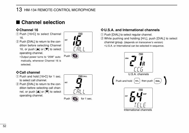
52
13 HM-134 REMOTE-CONTROL MICROPHONE
Channel selectionïïChannel 16q Push [16•C] to select Channel
16.w Push [DIAL] to return to the con-
dition before selecting Channel16, or push [Y] or [Z] to selectoperating channel.•Output power turns to “25W” auto-
matically, whenever Channel 16 is
selected.
ïïCall channelq Push and hold [16•C] for 1 sec.
to select call channel.w Push [DIAL] to return to the con-
dition before selecting call chan-nel, or push [Y] or [Z] to selectoperating channel.
ïïU.S.A. and International channelsq Push [DIAL] to select regular channel.w While pushing and holding [H/L], push [DIAL] to select
channel group. (depends on transceiver’s version)•U.S.A. or International can be selected in sequence.
DIALPush and hold then push
U.S.A. channels
International channels
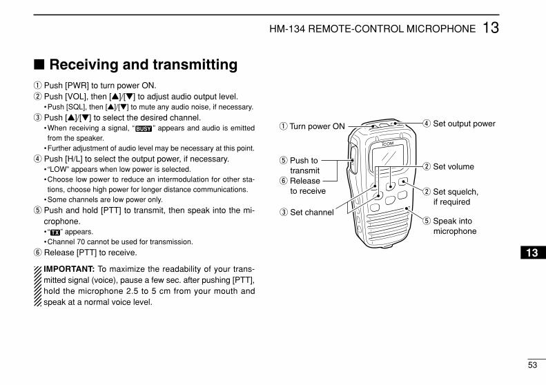
53
13HM-134 REMOTE-CONTROL MICROPHONE
13
Receiving and transmittingq Push [PWR] to turn power ON.w Push [VOL], then [Y]/[Z] to adjust audio output level.
•Push [SQL], then [Y]/[Z] to mute any audio noise, if necessary.
e Push [Y]/[Z] to select the desired channel.•When receiving a signal, “ ” appears and audio is emittedfrom the speaker.
•Further adjustment of audio level may be necessary at this point.
r Push [H/L] to select the output power, if necessary.• “LOW” appears when low power is selected.•Choose low power to reduce an intermodulation for other sta-tions, choose high power for longer distance communications.
•Some channels are low power only.
t Push and hold [PTT] to transmit, then speak into the mi-crophone.• “ ” appears.•Channel 70 cannot be used for transmission.
y Release [PTT] to receive.
IMPORTANT: To maximize the readability of your trans-mitted signal (voice), pause a few sec. after pushing [PTT],hold the microphone 2.5 to 5 cm from your mouth andspeak at a normal voice level.
w Set volume
w Set squelch, if required
r Set output power
t Speak into microphone
q Turn power ON
e Set channel
t Push to transmity Release to receive
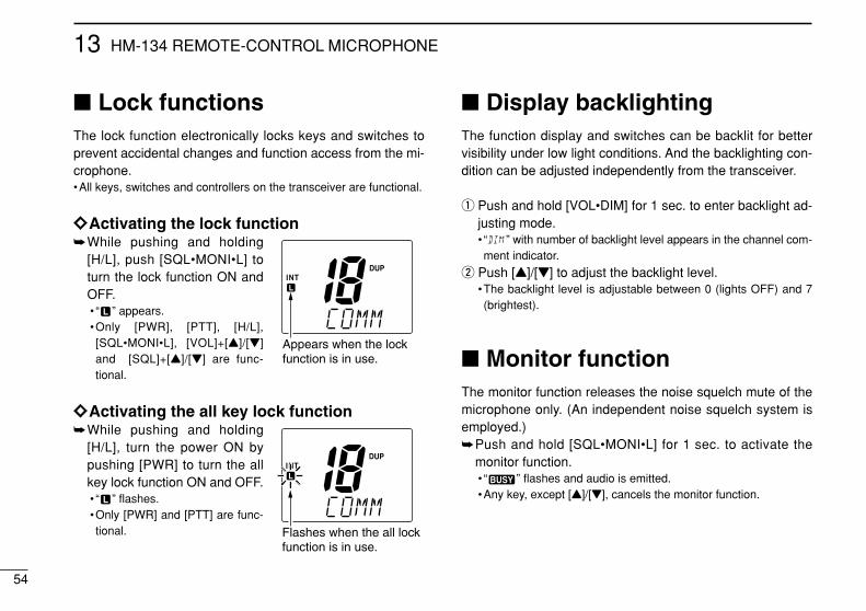
54
13 HM-134 REMOTE-CONTROL MICROPHONE
Lock functionsThe lock function electronically locks keys and switches toprevent accidental changes and function access from the mi-crophone.•All keys, switches and controllers on the transceiver are functional.
ïïActivating the lock functionWhile pushing and holding
[H/L], push [SQL•MONI•L] toturn the lock function ON andOFF.• “ ” appears.•Only [PWR], [PTT], [H/L],[SQL•MONI•L], [VOL]+[Y]/[Z]and [SQL]+[Y]/[Z] are func-tional.
ïïActivating the all key lock functionWhile pushing and holding
[H/L], turn the power ON bypushing [PWR] to turn the allkey lock function ON and OFF.• “ ” flashes.•Only [PWR] and [PTT] are func-tional.
Display backlightingThe function display and switches can be backlit for bettervisibility under low light conditions. And the backlighting con-dition can be adjusted independently from the transceiver.
q Push and hold [VOL•DIM] for 1 sec. to enter backlight ad-justing mode.• “ ” with number of backlight level appears in the channel com-ment indicator.
w Push [Y]/[Z] to adjust the backlight level.•The backlight level is adjustable between 0 (lights OFF) and 7(brightest).
Monitor functionThe monitor function releases the noise squelch mute of themicrophone only. (An independent noise squelch system isemployed.)Push and hold [SQL•MONI•L] for 1 sec. to activate the
monitor function.• “ ” flashes and audio is emitted.•Any key, except [Y]/[Z], cancels the monitor function.
Appears when the lockfunction is in use.
Flashes when the all lockfunction is in use.
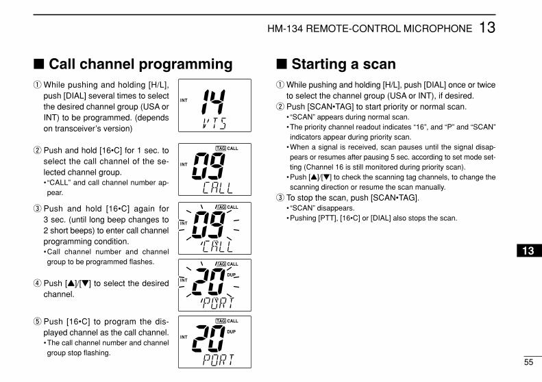
55
13HM-134 REMOTE-CONTROL MICROPHONE
13
Call channel programmingq While pushing and holding [H/L],
push [DIAL] several times to selectthe desired channel group (USA orINT) to be programmed. (dependson transceiver’s version)
w Push and hold [16•C] for 1 sec. toselect the call channel of the se-lected channel group.• “CALL” and call channel number ap-pear.
e Push and hold [16•C] again for3 sec. (until long beep changes to2 short beeps) to enter call channelprogramming condition.•Call channel number and channelgroup to be programmed flashes.
r Push [Y]/[Z] to select the desiredchannel.
t Push [16•C] to program the dis-played channel as the call channel.•The call channel number and channelgroup stop flashing.
Starting a scanq While pushing and holding [H/L], push [DIAL] once or twice
to select the channel group (USA or INT), if desired.w Push [SCAN•TAG] to start priority or normal scan.
• “SCAN” appears during normal scan.•The priority channel readout indicates “16”, and “P” and “SCAN”indicators appear during priority scan.
•When a signal is received, scan pauses until the signal disap-pears or resumes after pausing 5 sec. according to set mode set-ting (Channel 16 is still monitored during priority scan).
•Push [Y]/[Z] to check the scanning tag channels, to change thescanning direction or resume the scan manually.
e To stop the scan, push [SCAN•TAG].• “SCAN” disappears.•Pushing [PTT], [16•C] or [DIAL] also stops the scan.
56
13 HM-134 REMOTE-CONTROL MICROPHONE
Setting tag channelsq While pushing and holding [H/L], push [DIAL] once or twice
to select the channel group (USA and INT), if desired. (depends on transceiver’s version)
w Push [Y]/[Z] to select the desired channel to set as a tagchannel.
e Push and hold [SCAN•TAG] for 1 sec. to set the displayedchannel as a tag channel.• “ ” appears.
r To cancel the tag channel setting, push and hold[SCAN•TAG] for 1 sec.• “ ” disappears.
•Clearing all tag channels in the selected channel groupWhile pushing and holding [H/L], push [SCAN•TAG] for 3
sec. to clearing all tag channels. (until long beep changesto 2 short beeps)
Dualwatch/Tri-watchoperation
q Push [Y]/[Z] to select the desired channel.•While pushing and holding [H/L], push [DIAL] once or twice toselect the channel group (USA, INT), if desired. (depends ontransceiver’s version)
w Push [DUAL] to start dualwatch or tri-watch.• “DUAL” appears during dualwatch; “TRI” appears during tri-watch.
•Beep tone sounds when a signal is received on Channel 16.•Tri-watch becomes dualwatch when receiving a signal on the callchannel.
e To cancel dualwatch/tri-watch, push [DUAL•IC] again.
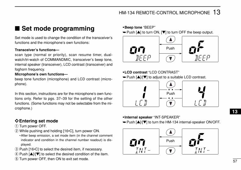
57
13HM-134 REMOTE-CONTROL MICROPHONE
13
Set mode programmingSet mode is used to change the condition of the transceiver’sfunctions and the microphone’s own functions:
Transceiver’s functions—scan type (normal or priority), scan resume timer, dual-watch/tri-watch of COMMANDMIC, transceiver’s beep tone,internal speaker (transceiver), LCD contrast (transceiver) andfoghorn frequency.Microphone’s own functions— beep tone function (microphone) and LCD contrast (micro-phone).
In this section, instructions are for the microphone’s own func-tions only. Refer to pgs. 37–39 for the setting of the otherfunctions. (Some functions may not be selectable from the mi-crophone.)
ïïEntering set modeq Turn power OFF.w While pushing and holding [16•C], turn power ON.
•After beep emission, a set mode item (in the channel commentindicator and condition in the channel number readout) is dis-played.
e Push [16•C] to select the desired item, if necessary.r Push [Y]/[Z] to select the desired condition of the item.t Turn power OFF, then ON to exit set mode.
•Beep tone “BEEP”Push [Y] to turn ON, [Z] to turn OFF the beep output.
•LCD contrast “LCD CONTRAST”Push [Y]/[Z] to adjust to a suitable LCD contrast.
• Internal speaker “INT-SPEAKER”Push [Y]/[Z] to turn the HM-134 internal-speaker ON/OFF.
Push• •
• •
Push
Push
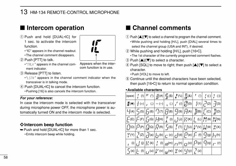
58
13 HM-134 REMOTE-CONTROL MICROPHONE
Intercom operationq Push and hold [DUAL•IC] for
1 sec. to activate the intercomfunction.• “IC” appears in the channel readout.•The channel comment disappears.
w Push [PTT] to talk.• “ ” appears in the channel com-ment indicator.
e Release [PTT] to listen.• “ ” appears in the channel comment indicator when thetransceiver is in talking mode.
r Push [DUAL•IC] to cancel the intercom function.•Pushing [16] is also cancels the intercom function.
For your reference:In case the intercom mode is selected with the transceiverduring microphone power OFF, the microphone power is au-tomatically turned ON and the intercom mode is selected.
ïï Intercom beep functionPush and hold [DUAL•IC] for more than 1 sec.
•Emits intercom beep while holding.
Channel commentsq Push [Y]/[Z] to select a channel to program the channel comment.
•While pushing and holding [H/L], push [DIAL] several times to
select the channel group (USA and INT), if desired.
w While pushing and holding [H/L], push [16•C].•The 1st character of the currently programmed comment flashes.
e Push [Y]/[Z] to select a character.r Push [SQL] to move to right; then push [Y]/[Z] to select a
character.•Push [VOL] to move to left.
t Continue until the desired characters have been selected,then push [16•C] to return to normal operation condition.
•Available characters
(r)
(s) (t) (u) (v) (w) (x) (y) (z)
(q)
(3)
(D)
(N)
(X)
(h)
(+)
(4)
(E)
(O)
(Y)
(i)
(–)
(5)
(F)
(P)
(Z)
(j)
()
(6)
(G)
(Q)
(a)
(k)
(/)
(7)
(H)
(R)
(b)
(l)
(,)
(8)
(I)
(S)
(c)
(m)
(space)
(9)
(T)
(d)
(n)
(0)
(A)
(U)
(e)
(o)
(1)
(B)
(V)
(f)
(p)
(2)
(C)
(J) (K) (L) (M)
(W)
(g)
(.)
( ))(( )(’)(&)(%)($)(#)(")(!)
Appears when the inter-com function is in use.
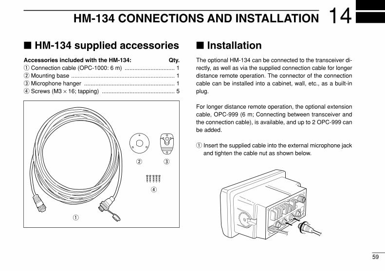
59
14HM-134 CONNECTIONS AND INSTALLATION
HM-134 supplied accessoriesAccessories included with the HM-134: Qty.q Connection cable (OPC-1000: 6 m) ............................... 1w Mounting base ................................................................ 1e Microphone hanger ........................................................ 1r Screws (M3 × 16; tapping) ............................................. 5
InstallationThe optional HM-134 can be connected to the transceiver di-rectly, as well as via the supplied connection cable for longerdistance remote operation. The connector of the connectioncable can be installed into a cabinet, wall, etc., as a built-inplug.
For longer distance remote operation, the optional extensioncable, OPC-999 (6 m; Connecting between transceiver andthe connection cable), is available, and up to 2 OPC-999 canbe added.
q Insert the supplied cable into the external microphone jackand tighten the cable nut as shown below.
q
w e
r
60
14 HM-134 CONNECTIONS AND INSTALLATION
w To use the supplied cable as a wall socket, follow thebelow steps.
e Using the mounting base, carefully mark off the 2 spotswhere the cable and screws will be fastened.
r Drill holes at these marks.t Install the mounting base using the supplied screws as
shown below.
y The completed installation should look like this.
Gasket
Cap
Mounting base Nut
Screw holes(approx. 2 (d) mm; 3⁄32″)
61
14HM-134 CONNECTIONS AND INSTALLATION
50 (
d) m
m
23 (
d) m
m
24 to
27
(d)
mm
5 mm
Gasket
Mounting base
Cap
Nut
2 mm2 mm x 3
24 to 27 (d) mm
INSTALLATION NOTES
Installation notesThe installation of this equipment should be made in such amanner as to respect the EC recommended electromagneticfield exposure limits (1999/519/EC).
The maximum RF power available from this device is 25watts. The antenna should be installed as high as possiblefor maximum efficiency and that this installation height shouldbe at least 5 meters above ground (or accessible) level. In thecase where an antenna cannot be installed at a reasonableheight, then the transmitter should neither be continuously op-erated for long periods if any person is within 5 meters of theantenna, nor operated at all if any person is touching the an-tenna.
In all cases any possible risk depends on the transmitterbeing activated for long periods. (actual recommendation lim-its are specified as an average of 6 minutes) Normally thetransmitter is not active for long periods of time. Some radio li-censes will require that a timer circuit automatically cuts thetransmitter after 1–2 minutes etc.
Similarly some types of transmitter, SSB, CW, AM, etc. have alower ‘average’ output power and the perceived risk is evenlower.
HM-134 TEMPLATE
24 to 27 (d) mm
2 mmHM-134
HM-134 TEMPLATE
Cut
her
e

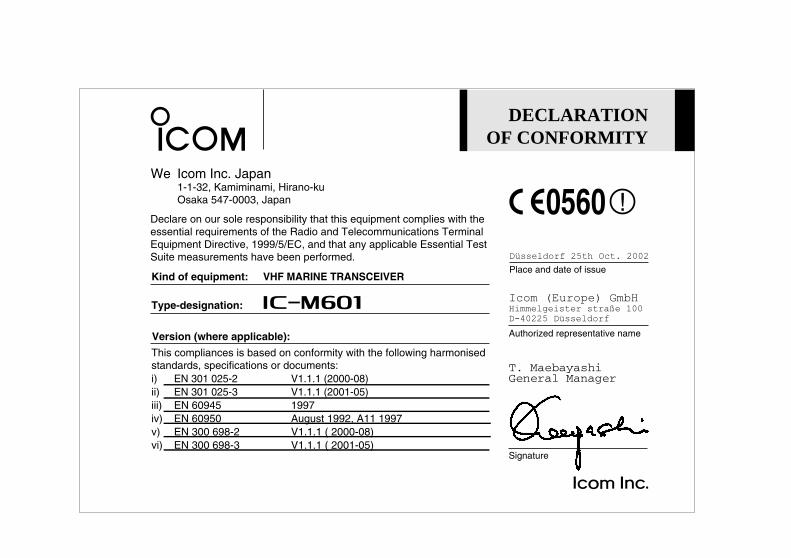
DECLARATIONOF CONFORMITY
We Icom Inc. Japan1-1-32, Kamiminami, Hirano-kuOsaka 547-0003, Japan
Kind of equipment: VHF MARINE TRANSCEIVER
This compliances is based on conformity with the following harmonisedstandards, specifications or documents:i) EN 301 025-2 V1.1.1 (2000-08)ii) EN 301 025-3 V1.1.1 (2001-05)iii) EN 60945 1997iv) EN 60950 August 1992, A11 1997v) EN 300 698-2 V1.1.1 ( 2000-08)vi) EN 300 698-3 V1.1.1 ( 2001-05)
Type-designation: iM601
Signature
T. MaebayashiGeneral Manager
Declare on our sole responsibility that this equipment complies with theessential requirements of the Radio and Telecommunications Terminal Equipment Directive, 1999/5/EC, and that any applicable Essential TestSuite measurements have been performed.
Version (where applicable):
0560
Authorized representative name
Icom (Europe) GmbHHimmelgeister stra§e 100
D-40225 Dsseldorf
Place and date of issue
Dsseldorf 25th Oct. 2002
Count on us!
1-1-32 Kamiminami, Hirano-ku, Osaka 547-0003 Japan
A-6218H-1EUPrinted in Japan© 2002 Icom Inc.
< Intended Country of Use > GER AUT GBR IRL
FRA NED BEL LUX
ESP POR ITA GRE
SWE DEN FIN SUI