Embed Size (px)
Citation preview
SQUARE WAVE TIG 255
OPERATOR’S MANUAL
Sales and Service through Subsidiaries and Distributors Worldwide
22801 St. Clair Ave. Cleveland, Ohio 44117-1199 U.S.A. Tel. (216) 481-8100
World's Leader in Welding and Cutting Products Premier Manufacturer of Industrial Motors
IM520-BJanuary, 1997
Safety Depends on YouLincoln arc welding and cuttingequipment is designed and builtwith safety in mind. However,your overal l safety can beincreased by proper installation ...and thoughtful operation on yourpart. DO NOT INSTALL,OPERATE OR REPAIR THISEQUIPMENT WITHOUTREADING THIS MANUAL ANDTHE SAFETY PRECAUTIONSCONTAINED THROUGHOUT.And, most importantly, thinkbefore you act and be careful.
For use with machines having Code Number 10022; 10023; 10024; 10025; 10026; 10134; 10301; 10302; 10303; 10451; 10452; 10453
– 2 –
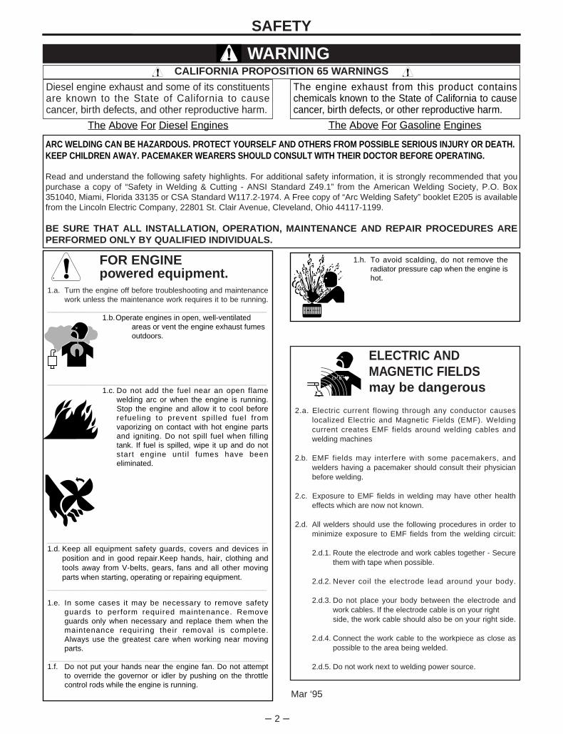
FOR ENGINEpowered equipment.
1.a. Turn the engine off before troubleshooting and maintenancework unless the maintenance work requires it to be running.
____________________________________________________1.b.Operate engines in open, well-ventilated
areas or vent the engine exhaust fumes outdoors.
____________________________________________________1.c. Do not add the fuel near an open flame
welding arc or when the engine is running.Stop the engine and allow it to cool beforerefueling to prevent spil led fuel fromvaporizing on contact with hot engine partsand igniting. Do not spill fuel when fillingtank. If fuel is spilled, wipe it up and do notstart engine unti l fumes have beeneliminated.
____________________________________________________1.d. Keep all equipment safety guards, covers and devices in
position and in good repair.Keep hands, hair, clothing andtools away from V-belts, gears, fans and all other movingparts when starting, operating or repairing equipment.
____________________________________________________
1.e. In some cases it may be necessary to remove safetyguards to perform required maintenance. Removeguards only when necessary and replace them when themaintenance requiring their removal is complete.Always use the greatest care when working near movingparts.
___________________________________________________1.f. Do not put your hands near the engine fan. Do not attempt
to override the governor or idler by pushing on the throttlecontrol rods while the engine is running.
SAFETY
ARC WELDING CAN BE HAZARDOUS. PROTECT YOURSELF AND OTHERS FROM POSSIBLE SERIOUS INJURY OR DEATH.KEEP CHILDREN AWAY. PACEMAKER WEARERS SHOULD CONSULT WITH THEIR DOCTOR BEFORE OPERATING.
Read and understand the following safety highlights. For additional safety information, it is strongly recommended that youpurchase a copy of “Safety in Welding & Cutting - ANSI Standard Z49.1” from the American Welding Society, P.O. Box351040, Miami, Florida 33135 or CSA Standard W117.2-1974. A Free copy of “Arc Welding Safety” booklet E205 is availablefrom the Lincoln Electric Company, 22801 St. Clair Avenue, Cleveland, Ohio 44117-1199.
BE SURE THAT ALL INSTALLATION, OPERATION, MAINTENANCE AND REPAIR PROCEDURES AREPERFORMED ONLY BY QUALIFIED INDIVIDUALS.
WARNING
Mar ‘95
ELECTRIC AND MAGNETIC FIELDSmay be dangerous
2.a. Electric current flowing through any conductor causes localized Electric and Magnetic Fields (EMF). Welding current creates EMF fields around welding cables and welding machines
2.b. EMF fields may interfere with some pacemakers, andwelders having a pacemaker should consult their physicianbefore welding.
2.c. Exposure to EMF fields in welding may have other healtheffects which are now not known.
2.d. All welders should use the following procedures in order tominimize exposure to EMF fields from the welding circuit:
2.d.1. Route the electrode and work cables together - Securethem with tape when possible.
2.d.2. Never coil the electrode lead around your body.
2.d.3. Do not place your body between the electrode andwork cables. If the electrode cable is on your right side, the work cable should also be on your right side.
2.d.4. Connect the work cable to the workpiece as close aspossible to the area being welded.
2.d.5. Do not work next to welding power source.
1.h. To avoid scalding, do not remove theradiator pressure cap when the engine ishot.
CALIFORNIA PROPOSITION 65 WARNINGS
Diesel engine exhaust and some of its constituentsare known to the State of California to causecancer, birth defects, and other reproductive harm.
The engine exhaust from this product containschemicals known to the State of California to causecancer, birth defects, or other reproductive harm.
The Above For Diesel Engines The Above For Gasoline Engines
– 3 –
SAFETY
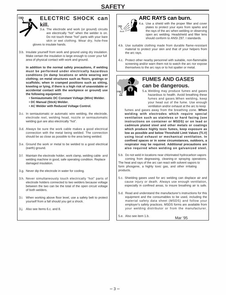
ARC RAYS can burn.4.a. Use a shield with the proper filter and cover
plates to protect your eyes from sparks andthe rays of the arc when welding or observingopen arc welding. Headshield and filter lensshould conform to ANSI Z87. I standards.
4.b. Use suitable clothing made from durable flame-resistantmaterial to protect your skin and that of your helpers fromthe arc rays.
4.c. Protect other nearby personnel with suitable, non-flammablescreening and/or warn them not to watch the arc nor exposethemselves to the arc rays or to hot spatter or metal.
ELECTRIC SHOCK cankill.3.a. The electrode and work (or ground) circuits
are electrically “hot” when the welder is on.Do not touch these “hot” parts with your bareskin or wet clothing. Wear dry, hole-free
gloves to insulate hands.
3.b. Insulate yourself from work and ground using dry insulation.Make certain the insulation is large enough to cover your fullarea of physical contact with work and ground.
In addition to the normal safety precautions, if weldingmust be performed under electrically hazardousconditions (in damp locations or while wearing wetclothing; on metal structures such as floors, gratings orscaffolds; when in cramped positions such as sitting,kneeling or lying, if there is a high risk of unavoidable oraccidental contact with the workpiece or ground) usethe following equipment:
• Semiautomatic DC Constant Voltage (Wire) Welder.• DC Manual (Stick) Welder.• AC Welder with Reduced Voltage Control.
3.c. In semiautomatic or automatic wire welding, the electrode,electrode reel, welding head, nozzle or semiautomaticwelding gun are also electrically “hot”.
3.d. Always be sure the work cable makes a good electricalconnection with the metal being welded. The connectionshould be as close as possible to the area being welded.
3.e. Ground the work or metal to be welded to a good electrical(earth) ground.
3.f. Maintain the electrode holder, work clamp, welding cable andwelding machine in good, safe operating condition. Replacedamaged insulation.
3.g. Never dip the electrode in water for cooling.
3.h. Never simultaneously touch electrically “hot” parts ofelectrode holders connected to two welders because voltagebetween the two can be the total of the open circuit voltageof both welders.
3.i. When working above floor level, use a safety belt to protectyourself from a fall should you get a shock.
3.j. Also see Items 6.c. and 8.
FUMES AND GASEScan be dangerous.5.a. Welding may produce fumes and gases
hazardous to health. Avoid breathing thesefumes and gases.When welding, keepyour head out of the fume. Use enoughventilation and/or exhaust at the arc to keep
fumes and gases away from the breathing zone. Whenwelding with electrodes which require specialventilation such as stainless or hard facing (seeinstructions on container or MSDS) or on lead orcadmium plated steel and other metals or coatingswhich produce highly toxic fumes, keep exposure aslow as possible and below Threshold Limit Values (TLV)using local exhaust or mechanical ventilation. Inconfined spaces or in some circumstances, outdoors, arespirator may be required. Additional precautions arealso required when welding on galvanized steel.
5.b. Do not weld in locations near chlorinated hydrocarbon vaporscoming from degreasing, cleaning or spraying operations.
The heat and rays of the arc can react with solvent vapors to form phosgene, a highly toxic gas, and other irritating products.
5.c. Shielding gases used for arc welding can displace air andcause injury or death. Always use enough ventilation,especially in confined areas, to insure breathing air is safe.
5.d. Read and understand the manufacturer’s instructions for thisequipment and the consumables to be used, including thematerial safety data sheet (MSDS) and follow youremployer’s safety practices. MSDS forms are available fromyour welding distributor or from the manufacturer.
5.e. Also see item 1.b. Mar ‘95

– 4 –
FOR ELECTRICALLYpowered equipment.
8.a. Turn off input power using the disconnectswitch at the fuse box before working onthe equipment.
8.b. Install equipment in accordance with the U.S. NationalElectrical Code, all local codes and the manufacturer’srecommendations.
8.c. Ground the equipment in accordance with the U.S. NationalElectrical Code and the manufacturer’s recommendations.
CYLINDER may explodeif damaged.7.a. Use only compressed gas cylinders
containing the correct shielding gas for theprocess used and properly operatingregulators designed for the gas and
pressure used. All hoses, fittings, etc. should be suitable forthe application and maintained in good condition.
7.b. Always keep cylinders in an upright position securelychained to an undercarriage or fixed support.
7.c. Cylinders should be located:• Away from areas where they may be struck or subjected tophysical damage.
• A safe distance from arc welding or cutting operations andany other source of heat, sparks, or flame.
7.d. Never allow the electrode, electrode holder or any otherelectrically “hot” parts to touch a cylinder.
7.e. Keep your head and face away from the cylinder valve outletwhen opening the cylinder valve.
7.f. Valve protection caps should always be in place and handtight except when the cylinder is in use or connected foruse.
7.g. Read and follow the instructions on compressed gascylinders, associated equipment, and CGA publication P-l,“Precautions for Safe Handling of Compressed Gases inCylinders,” available from the Compressed Gas Association1235 Jefferson Davis Highway, Arlington, VA 22202.
SAFETY
Mar ‘95
WELDING SPARKS cancause fire or explosion.6.a. Remove fire hazards from the welding area.
If this is not possible, cover them to preventthe welding sparks from starting a fire.Remember that welding sparks and hot
materials from welding can easily go through small cracksand openings to adjacent areas. Avoid welding nearhydraulic lines. Have a fire extinguisher readily available.
6.b. Where compressed gases are to be used at the job site,special precautions should be used to prevent hazardoussituations. Refer to “Safety in Welding and Cutting” (ANSIStandard Z49.1) and the operating information for theequipment being used.
6.c. When not welding, make certain no part of the electrodecircuit is touching the work or ground. Accidental contactcan cause overheating and create a fire hazard.
6.d. Do not heat, cut or weld tanks, drums or containers until theproper steps have been taken to insure that such procedureswill not cause flammable or toxic vapors from substancesinside. They can cause an explosion even though they havebeen “cleaned”. For information, purchase “RecommendedSafe Practices for the Preparation for Welding and Cutting ofContainers and Piping That Have Held HazardousSubstances”, AWS F4.1 from the American Welding Society(see address above).
6.e. Vent hollow castings or containers before heating, cutting orwelding. They may explode.
6.f. Sparks and spatter are thrown from the welding arc. Wear oilfree protective garments such as leather gloves, heavy shirt,cuffless trousers, high shoes and a cap over your hair. Wearear plugs when welding out of position or in confined places.Always wear safety glasses with side shields when in awelding area.
6.g. Connect the work cable to the work as close to the weldingarea as practical. Work cables connected to the buildingframework or other locations away from the welding areaincrease the possibility of the welding current passingthrough lifting chains, crane cables or other alternatecircuits. This can create fire hazards or overheat liftingchains or cables until they fail.
6.h. Also see item 1.c.
– 5 –
SAFETY
PRÉCAUTIONS DE SÛRETÉPour votre propre protection lire et observer toutes les instructionset les précautions de sûreté specifiques qui parraissent dans cemanuel aussi bien que les précautions de sûreté généralessuivantes:
Sûreté Pour Soudage A L’Arc1. Protegez-vous contre la secousse électrique:
a. Les circuits à l’électrode et à la piéce sont sous tensionquand la machine à souder est en marche. Eviter toujourstout contact entre les parties sous tension et la peau nueou les vétements mouillés. Porter des gants secs et sanstrous pour isoler les mains.
b. Faire trés attention de bien s’isoler de la masse quand onsoude dans des endroits humides, ou sur un planchermetallique ou des grilles metalliques, principalement dans les positions assis ou couché pour lesquelles une grandepartie du corps peut être en contact avec la masse.
c. Maintenir le porte-électrode, la pince de masse, le câblede soudage et la machine à souder en bon et sûr étatdefonctionnement.
d.Ne jamais plonger le porte-électrode dans l’eau pour lerefroidir.
e. Ne jamais toucher simultanément les parties sous tensiondes porte-électrodes connectés à deux machines à souderparce que la tension entre les deux pinces peut être letotal de la tension à vide des deux machines.
f. Si on utilise la machine à souder comme une source decourant pour soudage semi-automatique, ces precautionspour le porte-électrode s’applicuent aussi au pistolet desoudage.
2. Dans le cas de travail au dessus du niveau du sol, se protégercontre les chutes dans le cas ou on recoit un choc. Ne jamaisenrouler le câble-électrode autour de n’importe quelle partiedu corps.
3. Un coup d’arc peut être plus sévère qu’un coup de soliel,donc:
a. Utiliser un bon masque avec un verre filtrant appropriéainsi qu’un verre blanc afin de se protéger les yeux durayonnement de l’arc et des projections quand on soudeou quand on regarde l’arc.
b. Porter des vêtements convenables afin de protéger lapeau de soudeur et des aides contre le rayonnement del‘arc.
c. Protéger l’autre personnel travaillant à proximité ausoudage à l’aide d’écrans appropriés et non-inflammables.
4. Des gouttes de laitier en fusion sont émises de l’arc desoudage. Se protéger avec des vêtements de protection libresde l’huile, tels que les gants en cuir, chemise épaisse,pantalons sans revers, et chaussures montantes.
5. Toujours porter des lunettes de sécurité dans la zone desoudage. Utiliser des lunettes avec écrans lateraux dans les
zones où l’on pique le laitier.
6. Eloigner les matériaux inflammables ou les recouvrir afin deprévenir tout risque d’incendie dû aux étincelles.
7. Quand on ne soude pas, poser la pince à une endroit isolé dela masse. Un court-circuit accidental peut provoquer unéchauffement et un risque d’incendie.
8. S’assurer que la masse est connectée le plus prés possiblede la zone de travail qu’il est pratique de le faire. Si on placela masse sur la charpente de la construction ou d’autresendroits éloignés de la zone de travail, on augmente le risquede voir passer le courant de soudage par les chaines delevage, câbles de grue, ou autres circuits. Cela peutprovoquer des risques d’incendie ou d’echauffement deschaines et des câbles jusqu’à ce qu’ils se rompent.
9. Assurer une ventilation suffisante dans la zone de soudage.Ceci est particuliérement important pour le soudage de tôlesgalvanisées plombées, ou cadmiées ou tout autre métal quiproduit des fumeés toxiques.
10. Ne pas souder en présence de vapeurs de chlore provenantd’opérations de dégraissage, nettoyage ou pistolage. Lachaleur ou les rayons de l’arc peuvent réagir avec les vapeursdu solvant pour produire du phosgéne (gas fortement toxique)ou autres produits irritants.
11. Pour obtenir de plus amples renseignements sur la sûreté,voir le code “Code for safety in welding and cutting” CSAStandard W 117.2-1974.
PRÉCAUTIONS DE SÛRETÉ POURLES MACHINES À SOUDER ÀTRANSFORMATEUR ET ÀREDRESSEUR
1. Relier à la terre le chassis du poste conformement au code del’électricité et aux recommendations du fabricant. Le dispositifde montage ou la piece à souder doit être branché à unebonne mise à la terre.
2. Autant que possible, I’installation et l’entretien du poste seronteffectués par un électricien qualifié.
3. Avant de faires des travaux à l ’ interieur de poste, ladebrancher à l’interrupteur à la boite de fusibles.
4. Garder tous les couvercles et dispositifs de sûreté à leurplace.
Mar. ‘93

– 6 –
Thank You for selecting a QUALITY product by Lincoln Electric. We want youto take pride in operating this Lincoln Electric Company product••• as much pride as we have in bringing this product to you!
Read this Operators Manual completely before attempting to use this equipment. Save this manual and keep ithandy for quick reference. Pay particular attention to the safety instructions we have provided for your protection.The level of seriousness to be applied to each is explained below:
WARNINGThis statement appears where the information must be followed exactly to avoid serious personal injury orloss of life .
This statement appears where the information must be followed to avoid minor personal injury or damage tothis equipment .
CAUTION
Please Examine Carton and Equipment For Damage Immediatel yWhen this equipment is shipped, title passes to the purchaser upon receipt by the carrier. Consequently, Claimsfor material damaged in shipment must be made by the purchaser against the transportation company at thetime the shipment is received.
Please record your equipment identification information below for future reference. This information can befound on your machine nameplate.
Model Name & Number _____________________________________
Code & Serial Number _____________________________________
Date of Purchase _____________________________________
Whenever you request replacement parts for or information on this equipment always supply the informationyou have recorded above.
– 7 –
TABLE OF CONTENTS
Page
Safety .....................................................................................................................2-6
Installation................................................................................................................8-1 2Technical Specifications ............................................................................................8
Input and Output SpecificationsCable and Fuse SizesPhysical Dimensions
Location .....................................................................................................................9Machine Grounding....................................................................................................9Input Connections ....................................................................................................10Output Connections .................................................................................................11
Operation................................................................................................................13-23Safety Instructions ...................................................................................................13Graphic Symbols ................................................................................................14-15General Description .................................................................................................16Design Features and Advantages............................................................................16Welding Capability ...................................................................................................17Limitations................................................................................................................17Controls and Settings...............................................................................................18Hand and Foot Amptrol Operation ...........................................................................20Welding Operation ..............................................................................................20-23
Tig Welding Guidelines .......................................................................................20Tig Welding Sequence of Operation (2 Step Mode) ...........................................21Tig Welding Sequence of Operation (4 Step Mode) ...........................................22Advanced Tig Welding Features.........................................................................22Stick Welding ......................................................................................................23
Auxillary Power ........................................................................................................23Overload Protection .................................................................................................23
Accessories.................................................................................................................24
Maintenance ...........................................................................................................25-26Safety Precautions...................................................................................................25Routine and Periodic Maintenance ..........................................................................25General Assembly Exploded View...........................................................................26
Troubleshooting ....................................................................................................27-34How To Use Troubleshooting Guide........................................................................27Troubleshooting Guide .......................................................................................28-34
Wiring Diagrams ....................................................................................................35-36
Parts Manual .................................................................................................APPENDIX

– 8 –
INSTALLATIONTECHNICAL SPECIFICATIONS - SQUARE WAVE TIG 255
For all Stick, DC TIG, and Balanced AC TIGWelding at 255A/30V/40% Duty Cycle
Based on the 1993 US. NationalElectrical Code
For Unbalanced AC TIG Welding Above 180Amps, 255A/16V/40% Duty Cycle, Auto
Balance Based on the 1993 U.S. NationalElectrical Code
CodeNumber10022 10023 10024 10452 1045310451
Volts at Rated Amperes30
2826
Auxiliary Power115 Volts AC, 10 Amps
220Volts AC, 2 Amps(50/60 Hz. machines only)
Input Current atRated Output (1)
81/74/3774/37/3085/77/4477/45/3945/41/3377/45/41
Amps255
200150
Constant Open Circuit VoltageStick OCV: 76TIG OCV: 53
StandardVoltage
208/230/460/1/60230/460/575/1/60
200/240/400/1/50/60220/380/440/1/50/60380/415/500/1/50/60220/380/415/1/50/60
Duty Cycle40% Duty Cycle
NEMA Class II (40)60% Duty Cycle
100% Duty Cycle
Welding Current Range(Continuous)5-315 AmpsAC and DC
INPUT - SINGLE PHASE ONLY
RATED OUTPUT
OUTPUT
RECOMMENDED INPUT WIRE AND FUSE SIZES
Input
Voltage /
Frequency
208/60
230/60
460/60
575/60
200/50/60
220/50/60
380/50/60
400/50/60
415/50/60
440/50/60
500/50/60
Input
Ampere
Rating on
Nameplate
81
74
37
30
85
77
46
43
41
39
34
Type 75°C
Copper Ground
Wire in Conduit
AWG (IEC)
Sizes
6 (16mm2)
8 (10mm2)
10 (6mm2)
10 (6mm2)
6 (16mm2)
8 (10mm2)
8 (10mm2)
10 (6mm2)
10 (6mm2)
10 (6mm2)
10 (6mm2)
Fuse
(Super Lag)
or Breaker
Size
125
100
50
50
125
100
70
60
60
60
50
Type 75°C
Copper Wire in
Conduit AWG
(IEC) Sizes
6 (16mm2)
6 (16mm2)
10 (6mm2)
10 (6mm2)
6 (16mm2)
6 (16mm2)
8 (10mm2)
10 (6mm2)
10 (6mm2)
10 (6mm2)
10 (6mm2)
Type 75°C
Copper Ground
Wire in Conduit
AWG (IEC)
Sizes
6 (16mm2)
6 (16mm2)
10 (6mm2)
10 (6mm2)
6 (16mm2)
8 (10mm2)
8 (10mm2)
10 (6mm2)
10 (6mm2)
10 (6mm2)
10 (6mm2)
Type 75°C
Copper Wire in
Conduit AWG
(IEC) Sizes
4 (25mm2)
4 (25mm2)
8 (10mm2)
10 (6mm2)
4 (25mm2)
4 (25mm2)
8 (10mm2)
8 (10mm2)
8 (10mm2)
8 (10mm2)
10 (6mm2)
Input
Amperes
102
92
46
37
105
96
55
53
51
48
42
Height Width Depth Weight30.5 in. 19.0 in. 30.0 in.
(Lift bail, add 3.5 in) 300 lbs(137 kg)
775 mm 485 mm 760 mm(Lift bail, add 90 mm)
PHYSICAL DIMENSIONS
(1) Unbalanced TIG welding above 180 amps will draw higher input currents; see Supply Connections section.

– 9 –
INSTALLATIONRead entire installation section before startinginstallation.
Safety Precautions
SELECT SUITABLE LOCATION
Place the welder where clean cooling air can freelycirculate in through the rear louvers and out throughthe side louvers. Dirt, dust or any foreign material thatcan be drawn into the welder should be kept at aminimum. Failure to observe these precautions canresult in excessive operating temperatures andnuisance shut-downs.
STACKING
Square Wave TIG 255’s cannot be stacked.
TILTING
Each machine must be placed on a secure, levelsurface, either directly or on a recommendedundercarriage. The machine may topple over if thisprocedure is not followed.
ENVIRONMENTAL PROTECTION
Square Wave TIG 255 power sources carry an IP21protection rating. They are rated for use in rain-sheltered environments.
ELECTRIC SHOCK can kill.• Only qualified personnel should
perform this installation.
• Turn the input power OFF at the disconnect switch or fuse box before working on this equipment.
• Do not touch electrically hot parts.
• Always connect the Square Wave TIG 255 grounding terminal (located on the bottom of the input connection box) to a goodelectrical earth ground.
MACHINE GROUNDING AND HIGHFREQUENCY INTERFERENCEPROTECTION
The frame of the welder must be grounded. A groundterminal marked with the symbol is located atthe bottom of the input box for this purpose. See yourlocal and national electrical codes for propergrounding methods.
The spark gap oscil lator in the high frequencygenerator, being similar to a radio transmitter, can beblamed for many radio, TV and electronic equipmentinterference problems. These problems may be theresult of radiated interference. Proper groundingmethods can reduce or eliminate radiatedinterference.
Radiated interference can develop in the followingfour ways:
1. Direct interference radiated from the welder.
2. Direct interference radiated from the welding leads.
3. Direct interference radiated from feedback into thepower lines.
4. Interference from re-radiation of “pickup” byungrounded metallic objects.
Keeping these contributing factors in mind, installingequipment per the following instructions shouldminimize problems.
1. Keep the welder power supply lines as short aspossible and completely enclose them in rigidmetallic conduit or equivalent shielding for aminimum distance of 50 feet (15.2m). Thereshould be good electrical contact between thisconduit and the welder. Both ends of the conduitshould be connected to a driven ground and theentire length should be continuous.
2. Keep the work and electrode leads as short aspossible and as close together as possible.Lengths should not exceed 25 ft (7.6m). Tape theleads together when practical.
3. Be sure the torch and work cable rubber coveringsare free of cuts and cracks that allow highfrequency leakage. Cables with high naturalrubber content, such as Lincoln Stable-Arc® betterresist high frequency leakage than neoprene andother synthetic rubber insulated cables.
WARNING

– 10 –
INSTALLATION4. Keep the torch in good repair and all connections
tight to reduce high frequency leakage.
5. The work terminal must be connected to a groundwithin ten feet of the welder, using one of thefollowing methods:
a) A metal underground water pipe in directcontact with the earth for ten feet or more.
b) A 3/4” (19mm) galvanized pipe or a 5/8”(16mm) solid galvanized iron, steel or copperrod driven at least eight feet into the ground.
The ground should be securely made and thegrounding cable should be as short as possibleusing cable of the same size as the work cable, orlarger. Grounding to the building frame electricalconduit or a long pipe system can result in re-radiation, effectively making these membersradiating antennas.
6. Keep all access panels and covers securely inplace.
7. All electrical conductors within 50 ft (15.2m) of thewelder should be enclosed in grounded rigidmetallic conduit or equivalent shielding. Flexiblemetall ic conduit is generally not suitable.
8. When the welder is enclosed in a metal building,several good earth driven electrical grounds (as in5 (b) above) around the periphery of the buildingare recommended.
Failure to observe these recommended installationprocedures can cause radio or TV interferenceproblems and result in unsatisfactory weldingperformance resulting from lost high frequencypower.
See Figure 1 for the location of the rating plate, theentry hole, and the reconnect panel.
FIGURE 1 - REAR PANEL
1. RATING PLATE 3. 220V RECEPTACLE & BREAKER2. INPUT ENTRY & (50/60 HZ MACHINE ONLY)
RECONNECT PANEL 4. 115V RECEPTACLE & BREAKER
Have a qualified electrician connect the input leads toL1 and L2 of the input panel in accordance with alllocal codes and national electrical codes, and theconnection diagram located on the inside of the cover.Use a single phase line or one phase of a two or threephase line.
On multiple input voltage welders, be sure thereconnect panel is connected per the followinginstructions for the voltage being supplied to thewelder.
Failure to fol low these instructions can causeimmediate failure of components within the welder.___________________________________________
INPUT CONNECTIONS
Be sure the voltage, phase, and frequency of the inputpower is as specified on the rating plate, located onthe rear of the machine.
Welder supply line entry provision is in the case rearpanel with a removable cover over the inputconnection panel area. Entry is through a 1.7 in(43mm) diameter hole in the case back. Europeanmachines have a plastic bushing good for 3 - 10mm2
conductors. For larger input conductors a customersupplied plastic bushing should be used if required bylocal or national code specifications.
1
43
2
CAUTION
– 11 –
INSTALLATION
TABLE 1Cable Sizes for Combined Lengths of Copper
Electrode and Work Cable
Machine SizeLengths up to
100 ft 100 to 200 ft 200 to 250 ft
255 Amp40% Duty Cycle #2 (35mm2) #1 (45mm2) 1/0 (55mm2)
Welders are shipped connected for the highest inputvoltage as listed on the rating Plate. To change thisconnection for a different input voltage, reconnect thepower strap (P) to the terminal corresponding to theinput voltage used. Designations on reconnect panel,LOW, MID and HIGH correspond to the nameplateinput voltages of a triple voltage welder. Dual voltagewelders use only LOW and HIGH. Single voltagewelders use only HIGH.
EXAMPLE: On a 208/230/460 volt welder, LOW is208V, MID is 230V, and HIGH is 460V.
Fuse the input circuit with the recommended super lagfuses or delay type1 circuit breakers. Choose an inputand grounding wire size according to local or nationalcodes, refer to Specification page at the beginning ofthis chapter. Using fuses or circuit breakerssmaller than recommended may result in “nuisance”shut-offs from welder inrush currents even if notwelding at high currents.
Unbalanced AC TIG welding draws higher inputcurrents than those for stick, DC TIG, or Balanced ACTIG welding. The welder is designed for these higherinput currents. However, where unbalanced AC TIGwelding above 180 amps is planned, the higher inputcurrents require larger input wire sizes and fuses.Refer to Specification page at the beginning of thischapter.
The Square Wave TIG 255 should be permanentlywired into the power system. No plugs or connectorsare necessary.
1Also called “inverse time” or “thermal/magnetic”circuit breakers; circuit breakers which have a delayin tr ipping action that decreases as the magnitudeof the current increases.
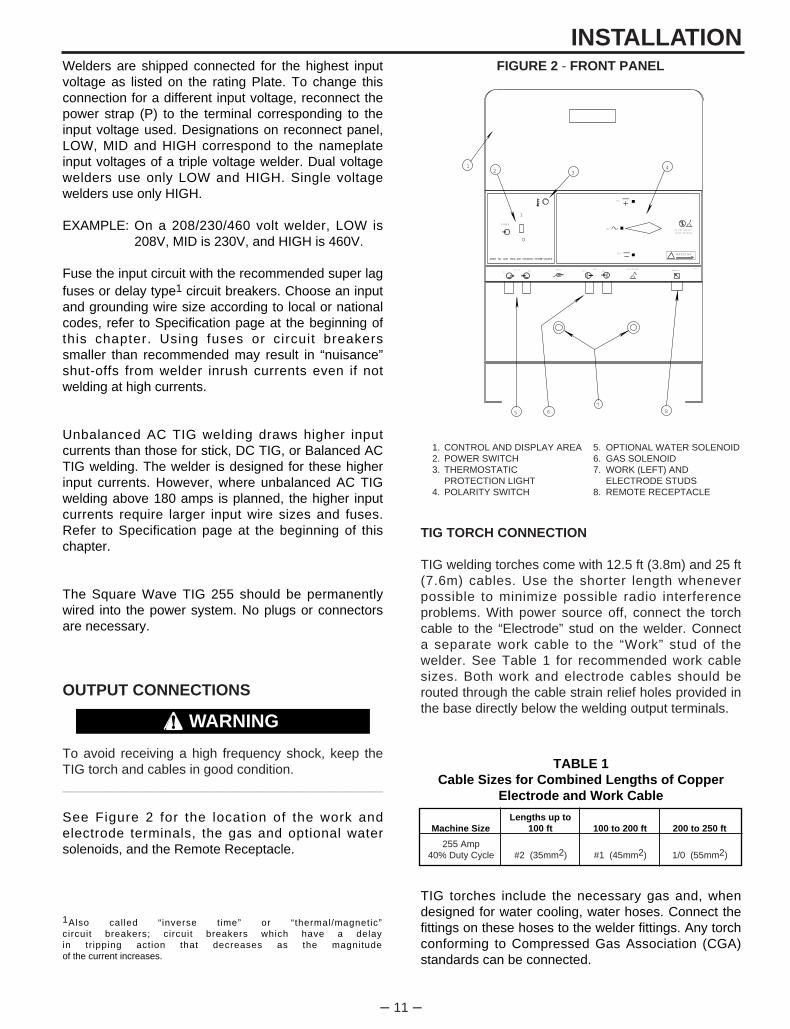
FIGURE 2 - FRONT PANEL
1. CONTROL AND DISPLAY AREA 5. OPTIONAL WATER SOLENOID2. POWER SWITCH 6. GAS SOLENOID3. THERMOSTATIC 7. WORK (LEFT) AND
PROTECTION LIGHT ELECTRODE STUDS4. POLARITY SWITCH 8. REMOTE RECEPTACLE
TIG TORCH CONNECTION
TIG welding torches come with 12.5 ft (3.8m) and 25 ft(7.6m) cables. Use the shorter length wheneverpossible to minimize possible radio interferenceproblems. With power source off, connect the torchcable to the “Electrode” stud on the welder. Connecta separate work cable to the “Work” stud of thewelder. See Table 1 for recommended work cablesizes. Both work and electrode cables should berouted through the cable strain relief holes provided inthe base directly below the welding output terminals.
TIG torches include the necessary gas and, whendesigned for water cooling, water hoses. Connect thefittings on these hoses to the welder fittings. Any torchconforming to Compressed Gas Association (CGA)standards can be connected.
DC
DC
AC
O
I
POWER
WARNING
ELECTRODEWORK GASINOUT
WATERIN
OUT
DO NOT SWITCH
WHILE WELDING
L9119-1
L9119-2
REMOTE
12 3
4
5 67
8
OUTPUT CONNECTIONS
To avoid receiving a high frequency shock, keep theTIG torch and cables in good condition.___________________________________________
See Figure 2 for the location of the work andelectrode terminals, the gas and optional watersolenoids, and the Remote Receptacle.
WARNING
– 12 –
INSTALLATION
DO NOT operate a water-cooled torch unless water isflowing. Water doesn’t flow until solenoid is actuated.
If using a water-cooled torch with a Magnum watercooler, connect the cooler water outlet to the ‘WaterValve In” fitting. Connect the TIG torch inlet to the“Water Valve Out” fitting.
If using a water-cooled torch with a free-running watersupply, install a water line between the welder “WaterInlet” and the supply. Include a strainer in the watersupply line to prevent dirt particles from obstructingwater flow in the valve and cooling chamber of theTIG torch. Failure to do so could result in water valvemalfunction and overheating of the water-cooledtorch. Connect the torch water line to the welder“Water Out” fitting. Use a nonmetallic drain line fromthe electrode connection to the drain or waterrecirculating pump.
For other conditions, consult the manufacturer’sinstructions for the water cooler or TIG torch beingused.
STICK ELECTRODE CABLE CONNECTION
Turn the Power switch Off. Run the electrode andwork cables through the strain relief holes below thewelding output terminals, and connect the cables tothe proper terminals. This strain relief preventsdamage to the welding output terminals if the cablesare pulled excessively. Select cable size according toTable 1.
Observe the safety precautions necessary forhandling and using compressed gas containers.Contact your supplier for specific information.___________________________________________
The welder fittings have the following threads: GasInlet and Outlet: 5/8”-18 right-hand female; Water inletand Outlet: 5/8”-18 left-hand female. The cylinder ofinert shielding gas must be equipped with a pressureregulator and flow meter. Install a hose between theflow meter and gas inlet on the welder.
WARNING
Do not connect a TIG torch and stick electrode cableat the same time. They will both be electrically HOTwhenever the output contactor is energized.___________________________________________
WARNING
– 13 –
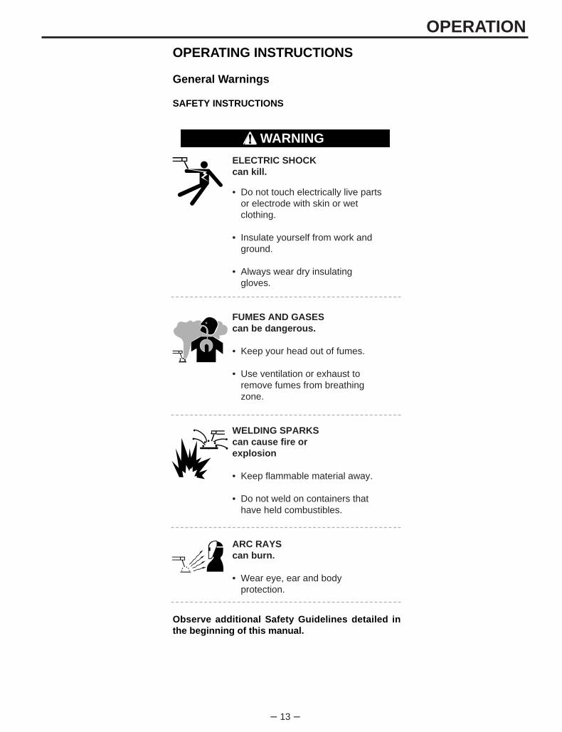
ELECTRIC SHOCKcan kill.
• Do not touch electrically live partsor electrode with skin or wetclothing.
• Insulate yourself from work andground.
• Always wear dry insulating gloves.
FUMES AND GASEScan be dangerous.
• Keep your head out of fumes.
• Use ventilation or exhaust toremove fumes from breathingzone.
WELDING SPARKScan cause fire orexplosion
• Keep flammable material away.
• Do not weld on containers thathave held combustibles.
ARC RAYScan burn.
• Wear eye, ear and bodyprotection.
OPERATIONOPERATING INSTRUCTIONS
General Warnings
SAFETY INSTRUCTIONS
Observe additional Safety Guidelines detailed inthe beginning of this manual.
WARNING
– 14 –
ON
2
A
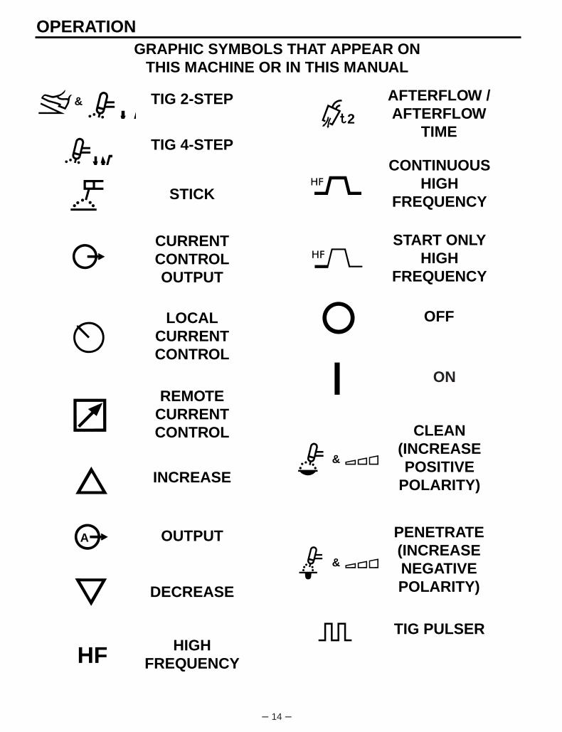
TIG 2-STEP
TIG 4-STEP
STICK
CURRENTCONTROLOUTPUT
LOCALCURRENTCONTROL
REMOTECURRENTCONTROL
INCREASE
OUTPUT
DECREASE
HIGHFREQUENCY
CONTINUOUSHIGH
FREQUENCY
START ONLYHIGH
FREQUENCY
OFF
CLEAN(INCREASEPOSITIVE
POLARITY)
PENETRATE(INCREASENEGATIVEPOLARITY)
TIG PULSER
AFTERFLOW /AFTERFLOW
TIME
GRAPHIC SYMBOLS THAT APPEAR ONTHIS MACHINE OR IN THIS MANUAL
OPERATION
&
&
&
HF

– 15 –
OVERTEMPERATURE
INPUTPOWER
DC+POLARITY
DC-POLARITY
DO NOTSWITCHWHILE
WELDING
WARNING
WATER(COOLANT)
OUTPUT
WATER(COOLANT)
INPUT
WORKCONNECTION
GAS OUTPUT
GAS INPUT
ELECTRODECONNECTION
PROTECTIVEGROUND
SINGLE PHASETRANSFORMER
AC & DCRECTIFIER
POWERSOURCE
TIG (GTAW)
SINGLEPHASE
PULSED PERSECOND
GRAPHIC SYMBOLS THAT APPEAR ONTHIS MACHINE OR IN THIS MANUAL (CONT.)
AC POLARITY
OPERATION
f
AC WAVEBALANCE
&
&
– 16 –
• Welding current limit can be preset from 5 to 315amps and is displayed on the Ammeter when notwelding.
• Auto Balance circuitry automatically provides theproper amount of cleaning and penetration when AC TIG welding. Manual AC wave balance adjust-ment is also possible.
• 2-Step/4-Step Arc Start Switch Capability.
• TIG Pulser with On/Off Selection, and Pulses PerSecond adjustment. Background current and dutycycle are automatically adjusted according to thepeak welding current.
• Fixed preflow time of 0.5 seconds. Preflow time iseliminated if welding restarts during gas afterflow ofprevious weld. This avoids unnecessary delayswhen making repeated welds.
• Adjustable afterflow time control.
• Local/Remote current selection.
• Stick/TlG selection.
• Continuous/Start/Off High Frequency selection.
• DC+/AC/DC- Polarity Switch.
• Power Factor Correction for lower input currents andsmaller input wire sizes.
• Remote Receptacle for Amptrol or Arc Start Switch.
• Low Voltage Arc Start Switch Circuit (24 V AC) formaximum operator safety.
• Gas and optional Water Valves: Inlet & outlet fittingsconform to Compressed Gas Association (CGA)standards.
• Built-in High Frequency Generator.
• 115 Volt Receptacle with 10 amp Circuit Breaker.
• 220 Volt European (Schuko) type receptacle with 2amp circuit breaker for water coolers (50/60Hzmachines only).
• Excellent arc starting and stability up through 315amps.
• High resistance to AC arc rectification.
• No tungsten spitt ing within current range ofelectrode.
• Compact size, requires only a 19 in x 30 in(485 mm x 760 mm) footprint.
GENERAL DESCRIPTION
The Square Wave TIG 255 is a constant current,single range square wave AC/DC TIG (GTAW) arcwelding power source with built-in high frequencystabilization. It also has stick (SMAW) capability. It isavailable from the factory in one model only; there areno factory installed options, only variations in inputvoltage and frequency.
The Square Wave TIG 255 includes advancedfeatures such as Auto-Balance™, 2-Step/4-Step ArcStart Switch operation and a TIG pulser. In addition,fixed preflow and variable afterflow timers areincluded for shielding gas and cooling water control.
Recommended Processes AndEquipment
The Square Wave TIG 255 is recommended for theTIG (GTAW) and stick (SMAW) welding processeswithin its output capacity of 5 to 315 amps, on bothAC and DC polarity. It is compatible with all MagnumTIG accessories (see Accessory section in thismanual), as well as many industry standarditems, such as TIG torches, hoses, and water coolers.
Operational Features and Controls
The Square Wave 255 has the following controls asstandard: TIG 2-Step/TlG 4-Step/Stick modeselection, Local/Remote current control selection,Continuous/Start Only/Off high frequency selection,Auto/Manual AC wave balance selection with themanual wave balance adjustment, TIG pulser On/Offselection with frequency adjustment, afterflowadjustment, and DC+/DC-/AC polarity selection.
Design Features and Advantages
• Designed to NEMA EW-1 & International IEC-974 Standards.
• Single output range of 5-315 amps covers themajority of all TIG welding applications.
• Solid State Output Contactor: no noise, no parts towear.
• Digital Ammeter and Voltmeter for precise readingsfrom 5 to 315 amps welding.
OPERATION
– 17 –
• Strain relief holes in base for welding cables, gasand water hoses and control cables.
• Easy access for input connections. Connectionsare simple strip and clamp of input wires (no lugsrequired).
• Low fan noise at idle.
• Modular construction for easy servicing.
• Simple keypad layout allows even novice users tooperate with minimal instruction.
• Unused controls are automatically locked out tosimplify setup. Examples: the AC wave balancecontrol has no effect in DC; the High Frequency andgas and water valves do not operate in Stick mode;TIG Pulser is locked out in the Stick mode.
• Recessed panels protect controls, output terminalsgas and water fittings.
• Large safety margins and protective circuits protectrectifiers from transient voltages and high currents.
• Submersion dipping of assembled transformer,choke, rectifier in special sealing/insulating materialgives added protection against moisture andcorrosive atmospheres.
• Line Voltage Compensated.
• Thermostatically Protected.
• Electronic Over Current Protection.
• Hinged Cover over Output Panel.
Limitations
Arc Gouging cannot be performed with the SquareWave TIG 255.
The Square Wave TIG 255 is not recommended forpipe thawing.
Welding Capability
The Square Wave TIG 255 is rated at 255 amps, 30volts, at 40% duty cycle on a ten minute basis. It iscapable of higher duty cycles at lower output currents.If the duty cycle(s) are exceeded, a thermal protectorwill shut off the output until the machine cools to areasonable operating temperature.
OPERATION
– 18 –
OPERATION
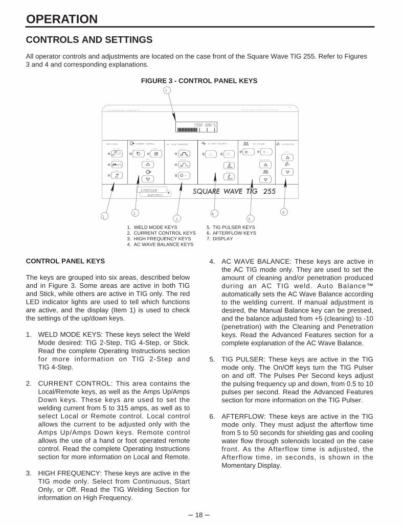
4. AC WAVE BALANCE: These keys are active inthe AC TIG mode only. They are used to set theamount of cleaning and/or penetration producedduring an AC TIG weld. Auto Balance™automatically sets the AC Wave Balance accordingto the welding current. If manual adjustment isdesired, the Manual Balance key can be pressed,and the balance adjusted from +5 (cleaning) to -10(penetration) with the Cleaning and Penetrationkeys. Read the Advanced Features section for acomplete explanation of the AC Wave Balance.
5. TIG PULSER: These keys are active in the TIGmode only. The On/Off keys turn the TIG Pulseron and off. The Pulses Per Second keys adjustthe pulsing frequency up and down, from 0.5 to 10pulses per second. Read the Advanced Featuressection for more information on the TIG Pulser.
6. AFTERFLOW: These keys are active in the TIGmode only. They must adjust the afterflow timefrom 5 to 50 seconds for shielding gas and coolingwater flow through solenoids located on the casefront. As the Afterflow time is adjusted, theAfterflow time, in seconds, is shown in theMomentary Display.
CONTROL PANEL KEYS
The keys are grouped into six areas, described belowand in Figure 3. Some areas are active in both TIGand Stick, while others are active in TIG only. The redLED indicator lights are used to tell which functionsare active, and the display (Item 1) is used to checkthe settings of the up/down keys.
1. WELD MODE KEYS: These keys select the WeldMode desired: TIG 2-Step, TIG 4-Step, or Stick.Read the complete Operating Instructions sectionfor more information on TIG 2-Step andTIG 4-Step.
2. CURRENT CONTROL: This area contains theLocal/Remote keys, as well as the Amps Up/AmpsDown keys. These keys are used to set thewelding current from 5 to 315 amps, as well as toselect Local or Remote control. Local controlallows the current to be adjusted only with theAmps Up/Amps Down keys. Remote controlallows the use of a hand or foot operated remotecontrol. Read the complete Operating Instructionssection for more information on Local and Remote.
3. HIGH FREQUENCY: These keys are active in theTIG mode only. Select from Continuous, StartOnly, or Off. Read the TIG Welding Section forinformation on High Frequency.
CONTROLS AND SETTINGS
All operator controls and adjustments are located on the case front of the Square Wave TIG 255. Refer to Figures3 and 4 and corresponding explanations.
FIGURE 3 - CONTROL PANEL KEYS
2
LINCOLNR
ELECTRIC
THE LINCOLN ELECTRIC COMPANY CLEVELAND, OHIO USA
ONOFF
TIG PULSERWELD MODE HIGH FREQUENCY AFTERFLOWCURRENT CONTROL
LOCAL REMOTE
STICK
TIG 2-STEP
TIG 4-STEP
HF
HF
CONTINUOUS
START ONLY
OFF
HF 2
SECONDS
PULSES PER SECONDAMPS
A
f
CLEAN
PENETRATE
AC WAVE BALANCE
AUTO-
BALANCE
MANUAL
BALANCE
G2612
AC/DC OUTPUT CAPACITY: 255 AMPS 30 VOLTS 40% DUTY CYCLE
7
12
3
4
5
6
1. WELD MODE KEYS 5. TIG PULSER KEYS2. CURRENT CONTROL KEYS 6. AFTERFLOW KEYS3. HIGH FREQUENCY KEYS 7. DISPLAY4. AC WAVE BALANCE KEYS
– 19 –
OPERATION
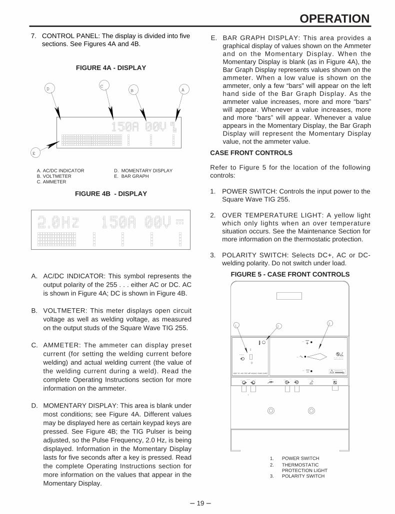
A. AC/DC INDICATOR: This symbol represents theoutput polarity of the 255 . . . either AC or DC. ACis shown in Figure 4A; DC is shown in Figure 4B.
B. VOLTMETER: This meter displays open circuitvoltage as well as welding voltage, as measuredon the output studs of the Square Wave TIG 255.
C. AMMETER: The ammeter can display presetcurrent (for setting the welding current beforewelding) and actual welding current (the value ofthe welding current during a weld). Read thecomplete Operating Instructions section for moreinformation on the ammeter.
D. MOMENTARY DISPLAY: This area is blank undermost conditions; see Figure 4A. Different valuesmay be displayed here as certain keypad keys arepressed. See Figure 4B; the TIG Pulser is beingadjusted, so the Pulse Frequency, 2.0 Hz, is beingdisplayed. Information in the Momentary Displaylasts for five seconds after a key is pressed. Readthe complete Operating Instructions section formore information on the values that appear in theMomentary Display.
CASE FRONT CONTROLS
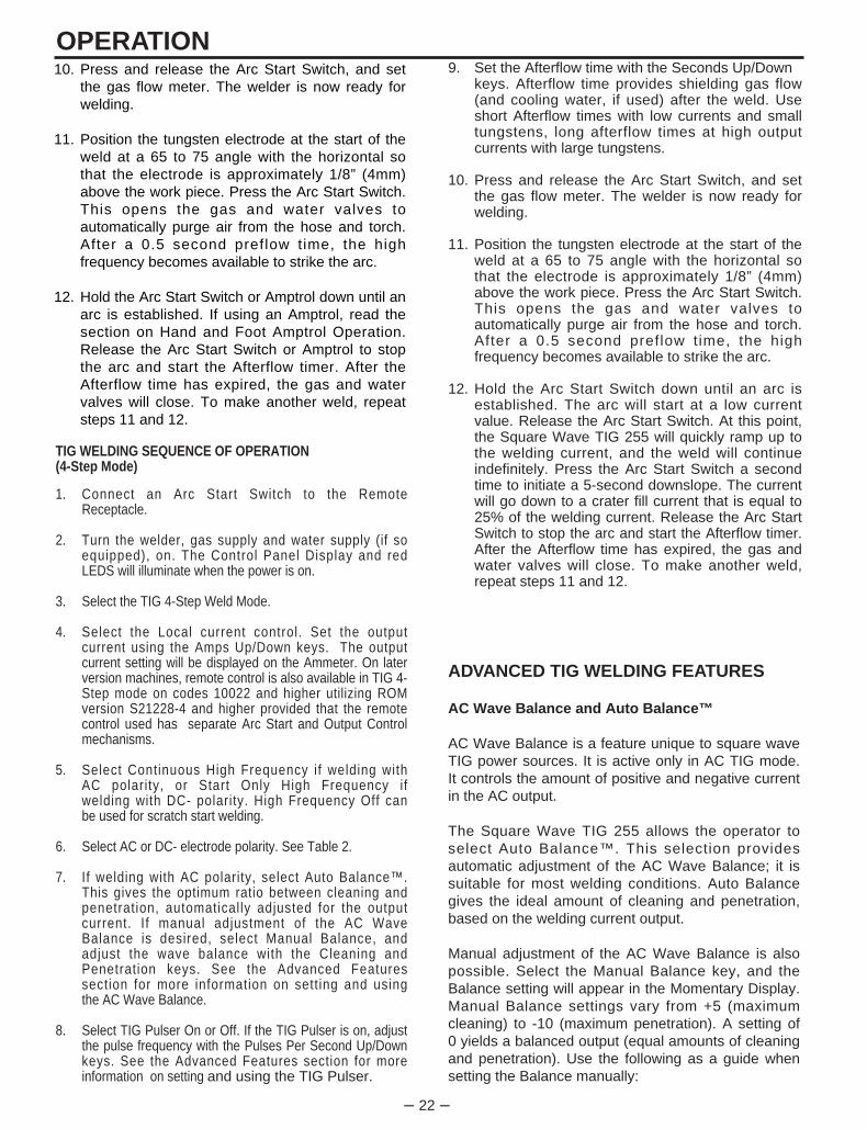
Refer to Figure 5 for the location of the followingcontrols:
1. POWER SWITCH: Controls the input power to theSquare Wave TIG 255.
2. OVER TEMPERATURE LIGHT: A yellow lightwhich only lights when an over temperaturesituation occurs. See the Maintenance Section formore information on the thermostatic protection.
3. POLARITY SWITCH: Selects DC+, AC or DC-welding polarity. Do not switch under load.
7. CONTROL PANEL: The display is divided into fivesections. See Figures 4A and 4B.
FIGURE 4A - DISPLAY
A. AC/DC INDICATOR D. MOMENTARY DISPLAYB. VOLTMETER E. BAR GRAPHC. AMMETER
FIGURE 4B - DISPLAY
ABC
D
E
E. BAR GRAPH DISPLAY: This area provides agraphical display of values shown on the Ammeterand on the Momentary Display. When theMomentary Display is blank (as in Figure 4A), theBar Graph Display represents values shown on theammeter. When a low value is shown on theammeter, only a few “bars” will appear on the lefthand side of the Bar Graph Display. As theammeter value increases, more and more “bars”will appear. Whenever a value increases, moreand more “bars” will appear. Whenever a valueappears in the Momentary Display, the Bar GraphDisplay will represent the Momentary Displayvalue, not the ammeter value.
FIGURE 5 - CASE FRONT CONTROLS
1. POWER SWITCH2. THERMOSTATIC
PROTECTION LIGHT3. POLARITY SWITCH
DC
DC
AC
O
I
POWER
WARNING
ELECTRODEWORK GASINOUT
WATERIN
OUT
DO NOT SWITCH
WHILE WELDING
L9119-1
L9119-2
REMOTE
1 23

– 20 –
TABLE 2RECOMMENDED POLARITY
SETTINGS FOR TIG WELDING
Type of WeldingElectrodePolarity
High FrequencySetting
Stainless Steel
Aluminum & Magnesium
Other Metals
DC-
AC
DC-
START
CONTINUOUS
START
OPERATIONWELDING OPERATION
TIG Welding
Familiarize yourself with the Controls and DisplaySection before attempting operation of the SquareWave TIG 255.
TIG Welding Guidelines
TIG welding can be done in either the TIG 2-Step orthe TIG 4-Step Weld Mode. TIG 2-Step is typicallyused with Hand or Foot Amptrols, with RemoteCurrent control. TIG 4-Step is typically used with ArcStart switches and Local Current Control, because itprovides a very brief current upslope, and a 5-secondcurrent downslope. TIG 4-Step also functions like atrigger interlock, making it unnecessary to hold downthe Arc Start switch during a weld. Note, on laterversions, TIG 4-Step was made available for use withRemote Current Control with the release of ROMversion S21228-4 (initiated on Control board G2150-3on codes 10022 and higher). This feature requiresthat the remote control devise in use must haveseparate Arc Start and Output Control mechanisms.Read the TIG Welding Sequence of Operationsections for more details on 2-Step and 4-StepOperation.
HAND AND FOOT AMPTROL ACCESSORYOPERATION
Both the Hand and Foot Amptrol work in a similarmanner. They are meant to be used for remote currentcontrol when Remote Current Control is selected.The TIG 2-Step mode must be selected when usingan Amptrol for remote current control. As explainedbelow, Amptrols can also be used as arc startswitches if Local Current Control is selected.
For simplicity, the following explanation will refer onlyto “Amptrols”, meaning both Foot and Hand models.The term “minimum” refers to a Foot pedal in the “up”position, as it would be with no foot pressure, or aHand Amptrol in the relaxed position, with no thumbpressure. “Maximum” refers to a fully depressed FootAmptrol, or a fully extended Hand Amptrol.
The Amptrol is capable of controlling the outputcurrent from 5 amps to the preset current displayed onthe ammeter. For example, if the ammeter is presetfor 200 amps and the Current Control switch is in theREMOTE position, the Amptrol, when depressed justpast its minimum position, will cause the SquareWave TIG 255 to weld at 5 amps. At the Amptrolsmaximum position, the output would be near 200amps.
It is important to note that, for many applications, thetungsten will not start an arc at only 5 amps. To startan arc reliably, it is important to depress the Amptrolfar enough so that the machine output current is nearthe tungsten operating range. In the example above, a3/32” tungsten may be used on DC- to weld near 200amps. To start the weld, the operator may have todepress the Amptrol approximately 1/4 of the waydown, or to nearly 50 amps, in order to start the arc.Merely depressing the Amptrol to its 5 amp minimumposition will not start the arc.
If the Current Control switch is set to the LOCALposition, an Amptrol can be used as an arc startswitch. Depressing the Amptrol just past minimum willcause the Amptrols built-in arc start switch to close,and backing off completely causes the built-in startswitch to open. The Amptrol will have no effect on thewelding current when used as an arc start switch.
– 21 –
OPERATION
7. If welding with AC polarity, select Auto Balance™.This gives the optimum ratio between cleaning andpenetration, automatically adjusted for the outputcurrent. If manual adjustment of the AC WaveBalance is desired, select Manual Balance, andadjust the wave balance with the Cleaning andPenetration keys. See the Advanced Featuressection for more information on setting and usingthe AC Wave Balance.
8. Select TIG Pulser On or Off. If the TIG Pulser ison, adjust the pulse frequency with the Pulses PerSecond Up/Down keys. See the AdvancedFeatures section for more information on settingand using the TIG Pulser.
9. Set the Afterflow time with the Seconds Up/Downkeys. Afterflow time provides shielding gas flow(and cooling water, if used) after the weld. Useshort Afterflow times with low currents and smalltungstens, use long afterflow times at high outputcurrents with large tungstens.
TIG WELDING SEQUENCE OF OPERATION(2-STEP MODE)
1. Connect an Arc Start Switch or an Amptrol to theRemote Receptacle.
2. Turn on the welder, gas supply and water supply (ifso equipped). The Control Panel Display and red LEDS will illuminate when the power is on.
3. Select the TIG 2-Step Weld Mode.
4. Select Local (if using an Arc Start Switch) orRemote (if using an Amptrol) current control. Setthe output current using the Amps Up/Down keys.The output current setting will be displayed on theAmmeter.
5. Select Continuous High Frequency if welding withAC polarity, or Start Only High Frequency ifwelding with DC- polarity. High Frequency Off canbe used for scratch start welding.
6. Select AC or DC- electrode polarity. See Table 2.
.010 (.25)0.020 (.50)0.040 (1.0)
1/16 (1.6)
3/32 (2.4)1/8 (3.2)
5/32 (4.0)3/16 (4.8)1/4 (6.4)
2-155-20
15-80
70-150
150-250250-400
400-500500-750
750-1000
(3)
(3)
(3)
10-20
15-3025-40
40-5555-80
80-125
2-155-15
10-60
50-100
100-160150-210
200-275250-350325-450
2-155-20
15-80
70-150
140-235225-325
300-400400-500500-630
2-1510-2020-30
30-80
60-130100-180
100-240190-300250-400
---5-20
20-60
60-120
100-180160-250
200-320290-390340-525
3-8 (2-4)5-10 (3-5)5-10 (3-5)
5-10 (3-5)
13-17 (6-8)15-23 (7-11)
21-25 (10-12)23-27 (11-13)28-32 (13-15)
3-8 (2-4)5-10 (3-5)5-10 (3-5)
9-13 (4-6)
11-15 (5-7)11-15 (5-7)
13-17 (6-8)18-22 (8-10)23-27(11-13)
#4, #5, #6
#5, #6
#6, #7, #8
#8, #10
1%, 2%ThoriatedTungsten
1%, 2%ThoriatedTungsten
PureTungsten
1%, 2%ThoriatedTungsten
ZirconiatedPure
Tungsten
1%, 2%ThoriatedTungsten
Zirconiated AluminumStainless
Steel
TungstenElectrodeDiameterin. (mm)
TIG TorchNozzle
Size (4), (5)
DCEN ( - ) DCEP ( + ) Unbalanced Wave Balanced Wave
AC Approximate ArgonGas Flow RateC.F.H. (1/min.)
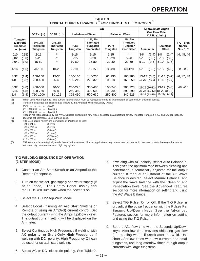
(1) When used with argon gas. The current ranges shown must be reduced when using argon/helium or pure helium shielding gasses.(2) Tungsten electrodes are classified as follows by the American Welding Society (AWS):
Pure . . . . . . . . . . . . . . . EWP1% Thoriated . . . . . . . . EWTh-12% Thoriated . . . . . . . . EWTh-2Though not yet recognized by the AWS, Ceriated Tungsten is now widely accepted as a substitute for 2% Thoriated Tungsten in AC and DC applications.
(3) DCEP is not commonly used in these sizes.(4) TIG torch nozzle “sizes” are in multiples of 1/16ths of an inch:
#4 = 1/4 in. (6 mm)#5 = 5/16 in. (8 mm)#6 = 3/8 in. (10 mm)#7 = 7/16 in. (11 mm)#8 = 1/2 in. (12.5 mm)
#10 = 5/8 in. (16 mm)(5) TIG torch nozzles are typically made from alumina ceramic. Special applications may require lava nozzles, which are less prone to breakage, but cannot
withstand high temperatures and high duty cycles.
TABLE 3TYPICAL CURRENT RANGES
(1)
FOR TUNGSTEN ELECTRODES (2)
– 22 –
OPERATION9. Set the Afterflow time with the Seconds Up/Down
keys. Afterflow time provides shielding gas flow(and cooling water, if used) after the weld. Useshort Afterflow times with low currents and smalltungstens, long afterflow times at high outputcurrents with large tungstens.
10. Press and release the Arc Start Switch, and setthe gas flow meter. The welder is now ready forwelding.
11. Position the tungsten electrode at the start of theweld at a 65 to 75 angle with the horizontal sothat the electrode is approximately 1/8” (4mm)above the work piece. Press the Arc Start Switch.This opens the gas and water valves toautomatically purge air from the hose and torch.After a 0.5 second preflow time, the highfrequency becomes available to strike the arc.
12. Hold the Arc Start Switch down until an arc isestablished. The arc will start at a low currentvalue. Release the Arc Start Switch. At this point,the Square Wave TIG 255 will quickly ramp up tothe welding current, and the weld will continueindefinitely. Press the Arc Start Switch a secondtime to initiate a 5-second downslope. The currentwill go down to a crater fill current that is equal to25% of the welding current. Release the Arc StartSwitch to stop the arc and start the Afterflow timer.After the Afterflow time has expired, the gas andwater valves will close. To make another weld,repeat steps 11 and 12.
TIG WELDING SEQUENCE OF OPERATION(4-Step Mode)
1. Connect an Arc Start Switch to the RemoteReceptacle.
2. Turn the welder, gas supply and water supply (if soequipped), on. The Control Panel Display and redLEDS will illuminate when the power is on.
3. Select the TIG 4-Step Weld Mode.
4. Select the Local current control. Set the output current using the Amps Up/Down keys. The output current setting will be displayed on the Ammeter. On laterversion machines, remote control is also available in TIG 4-Step mode on codes 10022 and higher utilizing ROMversion S21228-4 and higher provided that the remotecontrol used has separate Arc Start and Output Controlmechanisms.
5. Select Continuous High Frequency if welding withAC polarity, or Start Only High Frequency ifwelding with DC- polarity. High Frequency Off canbe used for scratch start welding.
6. Select AC or DC- electrode polarity. See Table 2.
7. If welding with AC polarity, select Auto Balance™.This gives the optimum ratio between cleaning andpenetration, automatically adjusted for the outputcurrent. If manual adjustment of the AC WaveBalance is desired, select Manual Balance, andadjust the wave balance with the Cleaning andPenetration keys. See the Advanced Featuressection for more information on setting and usingthe AC Wave Balance.
8. Select TIG Pulser On or Off. If the TIG Pulser is on, adjustthe pulse frequency with the Pulses Per Second Up/Downkeys. See the Advanced Features section for moreinformation on setting and using the TIG Pulser.
10. Press and release the Arc Start Switch, and setthe gas flow meter. The welder is now ready forwelding.
11. Position the tungsten electrode at the start of theweld at a 65 to 75 angle with the horizontal sothat the electrode is approximately 1/8” (4mm)above the work piece. Press the Arc Start Switch.This opens the gas and water valves toautomatically purge air from the hose and torch.After a 0.5 second preflow time, the highfrequency becomes available to strike the arc.
12. Hold the Arc Start Switch or Amptrol down until anarc is established. If using an Amptrol, read thesection on Hand and Foot Amptrol Operation.Release the Arc Start Switch or Amptrol to stopthe arc and start the Afterflow timer. After theAfterflow time has expired, the gas and watervalves will close. To make another weld, repeatsteps 11 and 12.
ADVANCED TIG WELDING FEATURES
AC Wave Balance and Auto Balance™
AC Wave Balance is a feature unique to square waveTIG power sources. It is active only in AC TIG mode.It controls the amount of positive and negative currentin the AC output.
The Square Wave TIG 255 allows the operator toselect Auto Balance™. This selection providesautomatic adjustment of the AC Wave Balance; it issuitable for most welding conditions. Auto Balancegives the ideal amount of cleaning and penetration,based on the welding current output.
Manual adjustment of the AC Wave Balance is alsopossible. Select the Manual Balance key, and theBalance setting will appear in the Momentary Display.Manual Balance settings vary from +5 (maximumcleaning) to -10 (maximum penetration). A setting of0 yields a balanced output (equal amounts of cleaningand penetration). Use the following as a guide whensetting the Balance manually:
– 23 –
OPERATION
50/60Hz MACHINES - (Codes 10024 thru 10026 & 10134)
Square Wave TIG 255 machines rated for 50/60Hzoperation provide 2 amps of 220 volt AC power at acontinental European (Schuko) type receptacle,located on the lower case back of the machine. Thiscircuit is protected from shorts and overloading by a 2amp circuit breaker, located above the receptacle.The auxiliary circuit is intended for running watercoolers whose current draw is within the 2 amp ratingof the receptacle. Note that some types of equipment,especially pumps and motors, have starting currentswhich are significantly higher than their runningcurrents. These higher starting currents may causethe circuit breaker to open. If this situation occurs, theuser should refrain from using the Square Wave TIG255 auxiliary for that equipment.
OVERLOAD PROTECTION
This welder has thermostatic protection fromexcessive duty cycles, overloads, loss of cooling, andhigh ambient temperatures. When the welder issubjected to an overload or loss of cooling, athermostat will open. This condition will be indicatedby the i l lumination of the yellow ThermostaticProtection Light on the case front (see Figure 2).Also, the Display will be blank, and all of the redControl Panel LEDS will be out. The fan will continueto run to cool the power source. No welding ispossible until the machine is allowed to cool and theThermostatic Protection Light goes out.
TIG Pulser
The Square Wave TIG 255 contains a unique TIGPulser circuit. The TIG Pulser has On/Off selections,as well as adjustments for Pulses Per SecondUp/Down. When the Pulser is turned On, or when thePulses Per Second are adjusted, the pulse frequency isshown in the Momentary Display. It can be variedfrom 0.5 Hz to 10 Hz in 0.5 Hz increments. (OneHertz {Hz} is equivalent to one pulse per second.)The background current (the welding current at thelow point of the pulse cycle) is automatically adjustedfrom 40% to 60% of the peak current by the SquareWave TIG 255. The duty cycle (the ratio between thattime spent at the peak current vs, the time spent atthe background current) is fixed at 50%.
STICK WELDING
1. Remove the amptrol or Arc Start Switch from theRemote Receptacle.
2. Turn the welder on. The Control Panel Displayand red LEDS will illuminate when the power is on.
3. Select Stick Mode and Local Current Control. Setthe output current using the Amps Up/Down keys.The output current setting will be displayed on theAmmeter. No other functions or adjustmentsoperate in the Stick Mode.
4. Select DC+, AC or DC- electrode polarity.
AUXILIARY POWER
ALL MACHINES
The Square Wave TIG 255 provides 10 amps of 115volt AC power at a standard NEMA 5-15R receptacle,located on the lower case back of the machine. Thiscircuit is protected from shorts and overloading by a10 amp circuit breaker, located next to the receptacle.The auxiliary circuit is intended for running watercoolers and small power tools, whose current draw iswithin the 10 amp rating. Note that some types ofequipment, especially pumps and large motors, havestarting currents which are significantly higher thantheir running current. These higher starting currentsmay cause the circuit breaker to open. If this situationoccurs, the user should refrain from using the SquareWave TIG 255 auxiliary for that equipment.
BALANCED (0): The amounts of posit ive andnegative are the same.
CLEANING (+1 to +5): Provides more positivecurrent than negative. Since the positivecurrent produces the “cleaning” or oxideremoval on aluminum, this setting is used forwelding on heavily oxidized aluminum.
PENETRATION (-1 to -10): Provides more negativecurrent than positive. The arc plasma will bemore concentrated and more easily directedto where the heat is needed. Higherpenetration settings allow a given size oftungsten to carry more current.
CAUTION: Use only the amount of cleaning requiredbecause the greater amount of positive current willheat the tungsten more and possibly cause it to meltor “spit”. Also, the arc is usually more flared and lessstable with more cleaning current.
In general, use just enough “cleaning” to removeoxides and to give good wetting to the puddle.
5. Clamp the electrode in the electrode holder, startthe weld by lightly touching the electrode to thework. Stop the weld by pulling the electrode awayfrom the work piece. Note, in Stick Mode the output studs remain electrically “HOT”.
– 24 –
ACCESSORIES
OPTIONS / ACCESSORIES
• Hand Amptrol (K963)
• Foot Amptrol (K870)
• Arc Start Switch (K814)
• Magnum Cooler Horizontal TIG Mounting Bracket(K559-2)
• Undercarriage (K932-1)
UNDERCARRIAGE FUNCTION
The Square Wave TIG 255 is designed to be usedwith a Lincoln K932-1 Undercarriage. Completeinstallation instructions are included with the K932-1undercarriage. When the undercarriage is properlyinstalled, the Square Wave TIG 255 lift bail is non-functional. Do not attempt to lift the power source withthe undercarriage attached. The undercarriage isdesigned for hand moving only; mechanized towingcan lead to injury and/or damage to the Square WaveTIG 255.
INSTALLATION OF FIELD INSTALLED OPTIONS
Instructions for connecting the K932-1 Undercarriageand the K559-2 Magnum Cooler Horizontal TIGMounting Bracket are included with thoseaccessories.
Installation of the K963 Hand Amptrol, the K814 ArcStart Switch and K870 Foot Amptrol are as follows:
Lift the Output Cover Door (if so equipped) on theSquare Wave TIG 255. Feed the cable up through thestrain relief holes in the base, and connect the 6-pinMS-type (Amphenol) connector to the RemoteReceptacle (See Figure 2). Secure with the threadedcollar.
– 25 –
MAINTENANCE
ELECTRIC SHOCK can kill.
• Only qualified personnel shouldperform this maintenance.
• Turn the input power OFF at thedisconnect switch or fuse boxbefore working on thisequipment.
• Do not touch electrically hot parts.
To avoid receiving a high frequency shock, keep theTIG torch and cables in good condition.
1. Disconnect power supply lines to machine before performing periodic maintenance.
2. Periodically clean the inside of the machine with alow pressure air system. Be sure to clean the following components thoroughly. See Figure 6 for location of those components.
• Main Transformer• Output Studs • Polarity Switch• Rectifier Assembly• Control Box Assembly• Spark Gap Assembly• Protection PC Board - (Mounted to rear of control box assembly)
3. Inspect welder output and control cables forfraying, cuts, and bare spots.
4. Keep TIG torch and cables in good condition.
5. The fan motor has sealed ball bearings whichrequire no maintenance.
6. Inspect spark gap spacing at regular intervals tomaintain a 0.015 in (0.4mm) gap. (Smallestpossible air gap consistent with good welding isdesirable to minimize R.F.I. problems.) Dressingor any refinishing of the spark gap contacts is notrecommended. If the contact surfaces becomeirregular or completely eroded, replacement of bothelectrodes is recommended.
MAINTENANCE
Safety Precautions
Routine and Periodic Maintenance
WARNING
WARNING
– 26 –
MAINTENANCE
38
1
522
11
2
6
4
28
3
2
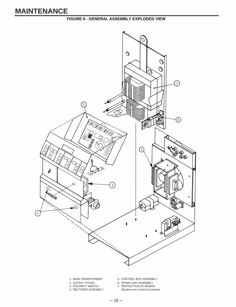
FIGURE 6 - GENERAL ASSEMBLY EXPLODED VIEW
1. MAIN TRANSFORMER 5. CONTROL BOX ASSEMBLY2. OUTPUT STUDS 6. SPARK GAP ASSEMBLY3. POLARITY SWITCH 7. PROTECTION PC BOARD - 4. RECTIFIER ASSEMBLY (Mounted to rear of control box assembly)
– 27 –
TROUBLESHOOTING How To Use Troubleshooting Guide
This Troubleshooting Guide is designed to be used by the machine Owner/Operator. Unauthorized repairsperformed on this equipment may result in danger to the technician and machine operator and will invalidate yourfactory warranty. For your safety, please observe all safety notes and precautions detailed in the Safety Section ofthis manual to avoid electrical shock or danger while troubleshooting this equipment.___________________________________________________________________________________________
This Troubleshooting Guide is provided to help youlocate and correct possible machine misadjustments.Simply follow the three-step procedure listed below.
Step 1. LOCATE PROBLEM (SYMPTOM)Look under the column labeled “PROBLEM(SYMPTOMS)”. This column describes possiblesymptoms that your machine may exhibit. Find thelisting that best describes the symptom that yourmachine is exhibiting.
Step 2. PERFORM EXTERNAL RECOMMENDED TESTS
The second column labeled “POSSIBLE AREAS OFMISADJUSTMENT(S)” lists the obvious externalpossibilities that may contribute to the machinesymptom. Perform these tests/checks in the orderlisted. In general, these tests can be conductedwithout removing the case wrap-around cover.
Step 3. CONSULT LOCAL AUTHORIZED FIELD SERVICE FACILITY
If you have exhausted all of the recommended tests instep 2, consult your local Authorized Field ServiceFacility.
If for any reason you do not understand the test procedures or are unable to perform the tests/repairs safely,contact your local Authorized Field Service Facility for technical troubleshooting assistance before you proceed.
CAUTION
WARNING
– 28 –
TROUBLESHOOTINGTroubleshooting Guide Observe Safety Guidelines
detailed in the beginning of this manual.
PROBLEMS(SYMPTOMS)
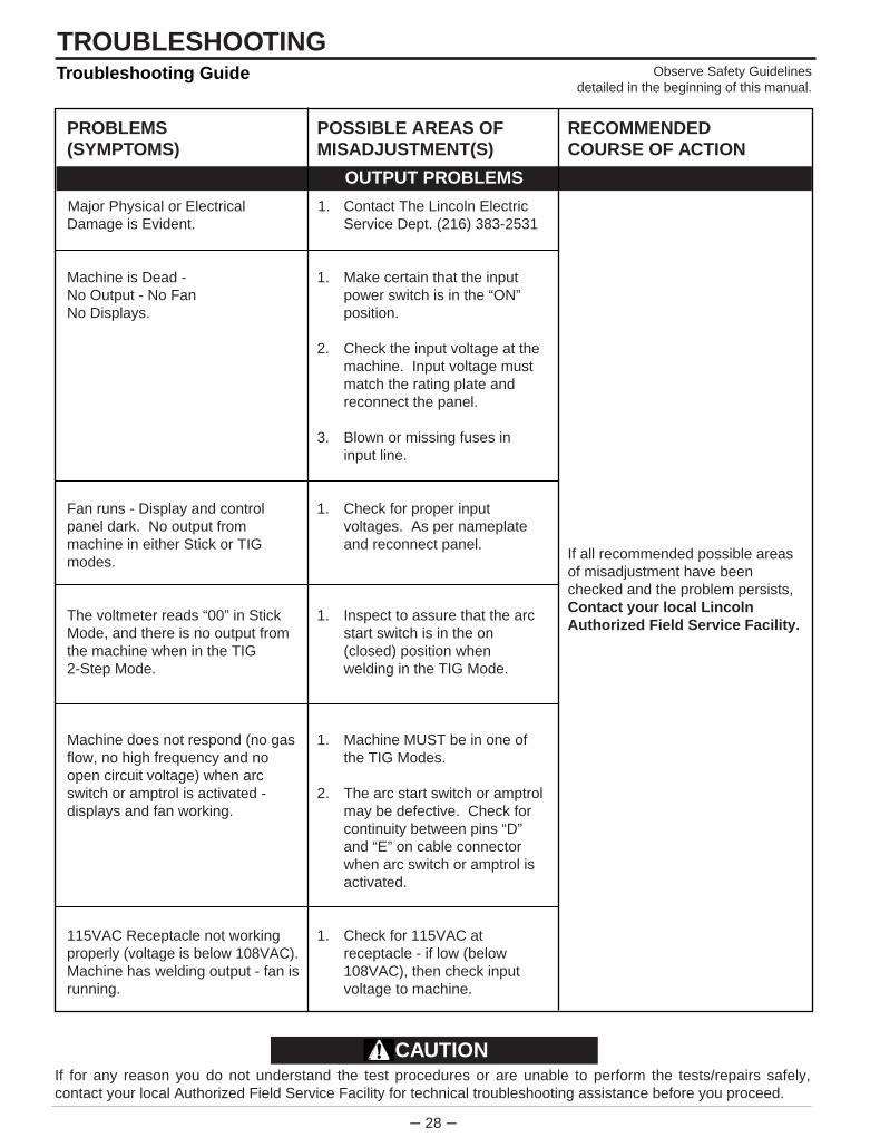
Major Physical or ElectricalDamage is Evident.
Machine is Dead - No Output - No FanNo Displays.
Fan runs - Display and controlpanel dark. No output frommachine in either Stick or TIGmodes.
The voltmeter reads “00” in StickMode, and there is no output fromthe machine when in the TIG2-Step Mode.
Machine does not respond (no gasflow, no high frequency and noopen circuit voltage) when arcswitch or amptrol is activated -displays and fan working.
115VAC Receptacle not workingproperly (voltage is below 108VAC).Machine has welding output - fan isrunning.
POSSIBLE AREAS OFMISADJUSTMENT(S)
1. Contact The Lincoln Electric Service Dept. (216) 383-2531
1. Make certain that the input power switch is in the “ON” position.
2. Check the input voltage at the machine. Input voltage must match the rating plate and reconnect the panel.
3. Blown or missing fuses in input line.
1. Check for proper input voltages. As per nameplate and reconnect panel.
1. Inspect to assure that the arc start switch is in the on (closed) position when welding in the TIG Mode.
1. Machine MUST be in one of the TIG Modes.
2. The arc start switch or amptrol may be defective. Check for continuity between pins “D” and “E” on cable connector when arc switch or amptrol is activated.
1. Check for 115VAC at receptacle - if low (below 108VAC), then check input voltage to machine.
RECOMMENDEDCOURSE OF ACTION
If all recommended possible areasof misadjustment have beenchecked and the problem persists,Contact your local LincolnAuthorized Field Service Facility.
OUTPUT PROBLEMS
If for any reason you do not understand the test procedures or are unable to perform the tests/repairs safely,contact your local Authorized Field Service Facility for technical troubleshooting assistance before you proceed.
CAUTION

– 29 –
TROUBLESHOOTINGObserve Safety Guidelinesdetailed in the beginning of this manual.
Troubleshooting Guide
PROBLEMS(SYMPTOMS)
Machine regularly over heats -thermostat opens, PL1 (yellow lighton front panel) glows. The fan runsbut machine has no output and nodisplay.
Machine makes a very loudbuzzing noise in DC Stick Mode, orin DC TIG Mode when the arc startor amptrol is pressed.
There is no current draw frommachine’s output studs.(The machine is not externallyloaded).
POSSIBLE AREAS OFMISADJUSTMENT(S)
1. Welding application may exceed recommended duty cycle.
2. Dirt and dust may have clogged the cooling channels inside the machine. Blow out unit with clean, dry compressed air.
3. Air intake and exhaust louvers may be blocked due to inadequate clearance around machine.
1. Inspect output stud insulators for cracks or signs of over-heating.
RECOMMENDEDCOURSE OF ACTION
If all recommended possible areasof misadjustment have beenchecked and the problem persists,Contact your local LincolnAuthorized Field Service Facility.
OUTPUT PROBLEMS
If for any reason you do not understand the test procedures or are unable to perform the tests/repairs safely,contact your local Authorized Field Service Facility for technical troubleshooting assistance before you proceed.
CAUTION

– 30 –
TROUBLESHOOTINGTroubleshooting Guide Observe Safety Guidelines
detailed in the beginning of this manual.
PROBLEMS(SYMPTOMS)
The yellow light (PL1) on the frontpanel is not lit.
One or more keypad lights (LEDS)are dark and cannot be lit whentheir respective keys are pressed -machine is operable.
The Beeper (Piezoelectric Buzzer)cannot be heard - machineoperating normally.
POSSIBLE AREAS OFMISADJUSTMENT(S)
1. Normal condition - this light will glow only if machine is in an overheated condition.(Thermal overload).
1. Be sure that the proper weld mode is selected. For example, the high frequency keys and keypad lights (LEDS) are not active in the stick mode.
1. Background noise may be too loud for user to hear beeper.
RECOMMENDEDCOURSE OF ACTION
If all recommended possible areasof misadjustment have beenchecked and the problem persists,Contact your local LincolnAuthorized Field Service Facility.
FUNCTION PROBLEMS
If for any reason you do not understand the test procedures or are unable to perform the tests/repairs safely,contact your local Authorized Field Service Facility for technical troubleshooting assistance before you proceed.
CAUTION
– 31 –
TROUBLESHOOTINGObserve Safety Guidelinesdetailed in the beginning of this manual.
Troubleshooting Guide
PROBLEMS(SYMPTOMS)
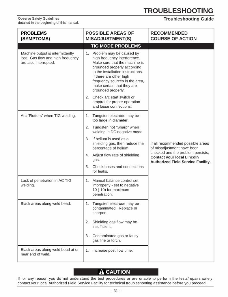
Machine output is intermittentlylost. Gas flow and high frequencyare also interrupted.
Arc “Flutters” when TIG welding.
Lack of penetration in AC TIGwelding.
Black areas along weld bead.
Black areas along weld bead at ornear end of weld.
POSSIBLE AREAS OFMISADJUSTMENT(S)
1. Problem may be caused by high frequency interference. Make sure that the machine is grounded properly according to the installation instructions. If there are other high frequency sources in the area, make certain that they are grounded properly.
2. Check arc start switch or amptrol for proper operation and loose connections.
1. Tungsten electrode may be too large in diameter.
2. Tungsten not “Sharp” when welding in DC negative mode.
3. If helium is used as a shielding gas, then reduce the percentage of helium.
4. Adjust flow rate of shielding gas.
5. Check hoses and connections for leaks.
1. Manual balance control set improperly - set to negative10 (-10) for maximum penetration.
1. Tungsten electrode may be contaminated. Replace or sharpen.
2. Shielding gas flow may be insufficient.
3. Contaminated gas or faulty gas line or torch.
1. Increase post flow time.
RECOMMENDEDCOURSE OF ACTION
If all recommended possible areasof misadjustment have beenchecked and the problem persists,Contact your local LincolnAuthorized Field Service Facility.
TIG MODE PROBLEMS
If for any reason you do not understand the test procedures or are unable to perform the tests/repairs safely,contact your local Authorized Field Service Facility for technical troubleshooting assistance before you proceed.
CAUTION
– 32 –
TROUBLESHOOTINGTroubleshooting Guide Observe Safety Guidelines
detailed in the beginning of this manual.
PROBLEMS(SYMPTOMS)
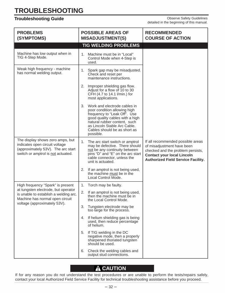
Machine has low output when inTIG 4-Step Mode.
Weak high frequency - machinehas normal welding output.
The display shows zero amps, butindicates open circuit voltage(approximately 53V). The arc startswitch or amptrol is not actuated.
High frequency “Spark” is presentat tungsten electrode, but operatoris unable to establish a welding arc.Machine has normal open circuitvoltage (approximately 53V).
POSSIBLE AREAS OFMISADJUSTMENT(S)
1. Machine must be in “Local” Control Mode when 4-Step is used.
1. Spark gap may be misadjusted.Check and reset per maintenance instructions.
2. Improper shielding gas flow. Adjust for a flow of 10 to 30 CFH (4.7 to 14.1 l/min.) for most applications.
3. Work and electrode cables in poor condition allowing high frequency to “Leak Off”. Use good quality cables with a high natural rubber content, such as Lincoln Stable Arc Cable. Cables should be as short as possible.
1. The arc start switch or amptrol may be defective. There shouldnot be any continuity between pins “D” and “E” on the arc startcable connector, unless the unit is actuated.
2. If an amptrol is not being used, the machine must be in the Local Control Mode.
1. Torch may be faulty.
2. If an amptrol is not being used, then the machine must be in the Local Control Mode.
3. Tungsten electrode may be too large for the process.
4. If helium shielding gas is being used, then reduce percentage of helium.
5. If TIG welding in the DC negative mode, then a properlysharpened thoriated tungsten should be used.
6. Check the welding cables and output stud connections.
RECOMMENDEDCOURSE OF ACTION
If all recommended possible areasof misadjustment have beenchecked and the problem persists,Contact your local LincolnAuthorized Field Service Facility.
TIG WELDING PROBLEMS
If for any reason you do not understand the test procedures or are unable to perform the tests/repairs safely,contact your local Authorized Field Service Facility for technical troubleshooting assistance before you proceed.
CAUTION

– 33 –
TROUBLESHOOTINGObserve Safety Guidelinesdetailed in the beginning of this manual.
Troubleshooting Guide
PROBLEMS(SYMPTOMS)
No high frequency. Machine is inthe TIG Mode and has normaloutput.
No gas or water flow when arc startswitch or amptrol is activated in theTIG Mode. Machine has output -fan runs. When toggling betweenthe Stick and TIG Modes a “Click”can be heard indicating that thesolenoids are operating.
Arc rectification when AC TIGwelding.
POSSIBLE AREAS OFMISADJUSTMENT(S)
1. In order for the high frequency to operate, the machine must be either in the start only Mode or the continuous high frequency mode.
2. The high frequency spark gap may be too large or shorted. Check gap as per maintenance instructions.
1. Gas supply is empty or not turned on.
2. Gas or water hose may be pinched.
3. Gas or water solenoid may be blocked with dirt. Use filters to prevent reoccurrence.Consult your Local welder/gas distributor.
1. Tungsten electrode may be too small for process.
2. Manual balance control may be misadjusted. Readjust to the negative direction.
3. If helium gas is being used, reduce percentage of helium.
RECOMMENDEDCOURSE OF ACTION
If all recommended possible areasof misadjustment have beenchecked and the problem persists,Contact your local LincolnAuthorized Field Service Facility.
TIG WELDING PROBLEMS
If for any reason you do not understand the test procedures or are unable to perform the tests/repairs safely,contact your local Authorized Field Service Facility for technical troubleshooting assistance before you proceed.
CAUTION
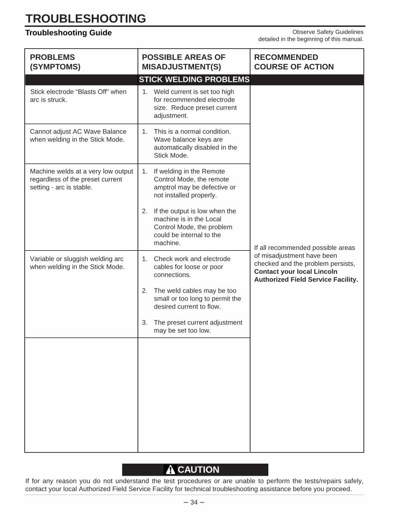
– 34 –
TROUBLESHOOTINGTroubleshooting Guide Observe Safety Guidelines
detailed in the beginning of this manual.
PROBLEMS(SYMPTOMS)
Stick electrode “Blasts Off” whenarc is struck.
Cannot adjust AC Wave Balancewhen welding in the Stick Mode.
Machine welds at a very low outputregardless of the preset currentsetting - arc is stable.
Variable or sluggish welding arcwhen welding in the Stick Mode.
POSSIBLE AREAS OFMISADJUSTMENT(S)
1. Weld current is set too high for recommended electrode size. Reduce preset current adjustment.
1. This is a normal condition. Wave balance keys are automatically disabled in the Stick Mode.
1. If welding in the Remote Control Mode, the remote amptrol may be defective or not installed properly.
2. If the output is low when the machine is in the Local Control Mode, the problem could be internal to the machine.
1. Check work and electrode cables for loose or poor connections.
2. The weld cables may be too small or too long to permit the desired current to flow.
3. The preset current adjustment may be set too low.
RECOMMENDEDCOURSE OF ACTION
If all recommended possible areasof misadjustment have beenchecked and the problem persists,Contact your local LincolnAuthorized Field Service Facility.
STICK WELDING PROBLEMS
If for any reason you do not understand the test procedures or are unable to perform the tests/repairs safely,contact your local Authorized Field Service Facility for technical troubleshooting assistance before you proceed.
CAUTION
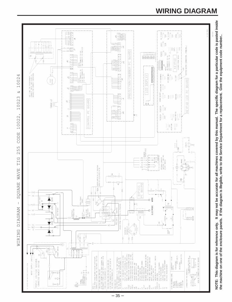
– 35 –
WIRING DIAGRAM
231
TO GROUND PER NATIONAL ELECTRIC CODE
229
PIEZO
BUZZER
(-)
(+)
C1
(1,3)
(1,2)
(1,1)
(2,2)
(2,1)
(3,1)
(4,1)
(4,2)
(5,1)
(5,2)
TO KEYPAD MATRIX
X1
240
230
230D
230B
50/60 HZ
237238
236A
C2
232
230C
MACHINES ONLY
230E
236
235
232B
229A
239A
239
235A
238A
R3
R4
52A
4-19-96D
G2719
WIRING DIAGRAM - SQUARE WAVE TIG 255 CODE 10022, 10023 & 10024
NO
TE
: T
his
dia
gra
m is
fo
r re
fere
nce
onl
y.
It m
ay n
ot
be
accu
rate
fo
r al
l mac
hine
s co
vere
d b
y th
is m
anua
l. T
he s
pec
ific
dia
gra
m f
or
a p
artic
ular
co
de
is p
aste
d in
sid
eth
e m
achi
ne o
n o
ne o
f th
e en
clo
sure
pan
els.
If
the
dia
gra
m is
ille
gib
le, w
rite
to
the
Ser
vice
Dep
artm
ent
for
a re
pla
cem
ent.
Giv
e th
e eq
uip
men
t co
de
num
ber
..
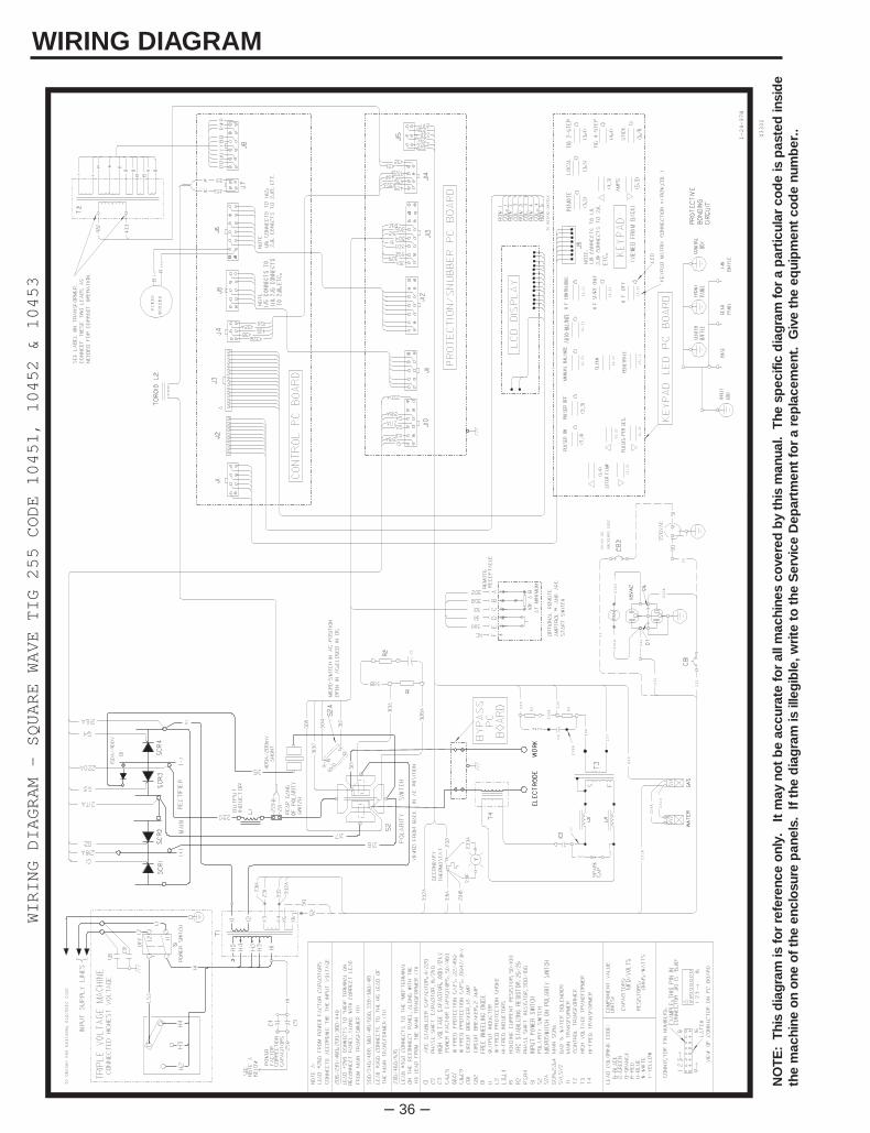
– 36 –
WIRING DIAGRAM
231
TO GROUND PER NATIONAL ELECTRIC CODE
229
PIEZO
BUZZER
(-)
(+)
C1
(1,3)
(1,2)
(1,1)
(2,2)
(2,1)
(3,1)
(4,1)
(4,2)
(5,1)
(5,2)
TO KEYPAD MATRIX
X1
240
231
231D
231B
50/60 HZ
237238
236A
C2
232B
231C
MACHINES ONLY
236
235
232C
229A
239A
239
235A
238A
R3
R4
1-24-97H
G3302
WIRING DIAGRAM - SQUARE WAVE TIG 255 CODE 10451, 10452 & 10453
52
50
232
NO
TE
: T
his
dia
gra
m is
fo
r re
fere
nce
onl
y.
It m
ay n
ot
be
accu
rate
fo
r al
l mac
hine
s co
vere
d b
y th
is m
anua
l. T
he s
pec
ific
dia
gra
m f
or
a p
artic
ular
co
de
is p
aste
d in
sid
eth
e m
achi
ne o
n o
ne o
f th
e en
clo
sure
pan
els.
If
the
dia
gra
m is
ille
gib
le, w
rite
to
the
Ser
vice
Dep
artm
ent
for
a re
pla
cem
ent.
Giv
e th
e eq
uip
men
t co
de
num
ber
..
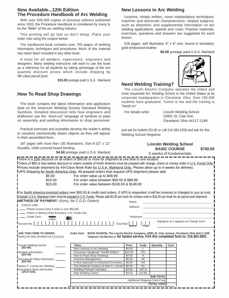
Now Available...12th EditionThe Procedure Handbook of Arc Welding
With over 500,000 copies of previous editions publishedsince 1933, the Procedure Handbook is considered by many to be the “Bible” of the arc welding industry.
This printing wil l go fast so don’t delay. Place your order now using the coupon below.
The hardbound book contains over 750 pages of weldinginformation, techniques and procedures. Much of this material has never been included in any other book.
A must for al l welders, supervisors, engineers anddesigners. Many welding instructors will want to use the bookas a reference for all students by taking advantage of the lowquantity discount prices which include shipping by4th class parcel post.
$15.00 postage paid U.S.A. Mainland
How To Read Shop Drawings
The book contains the latest information and applicationdata on the American Welding Society Standard WeldingSymbols. Detailed discussion tells how engineers anddraftsmen use the “short-cut” language of symbols to passon assembly and welding information to shop personnel.
Practical exercises and examples develop the reader’s abilityto visualize mechanically drawn objects as they will appearin their assembled form.
187 pages with more than 100 illustrations. Size 8-1/2” x 11”Durable, cloth-covered board binding.
$4.50 postage paid U.S.A. Mainland
New Lessons in Arc WeldingLessons, simply written, cover manipulatory techniques;
machine and electrode characteristics; related subjects,such as distortion; and supplemental information on arcwelding applications, speeds and costs. Practice materials,exercises, questions and answers are suggested for each lesson.
528 pages, well illustrated, 6” x 9” size, bound in simulated,gold embossed leather.
$5.00 postage paid U.S.A. Mainland
Need Welding Training?The Lincoln Electric Company operates the oldest and
most respected Arc Welding School in the United States at itscorporate headquarters in Cleveland, Ohio. Over 100,000students have graduated. Tuition is low and the training is “hands on”
For details write: Lincoln Welding School22801 St. Clair Ave. Cleveland, Ohio 44117-1199.
and ask for bulletin ED-80 or call 216-383-2259 and ask for theWelding School Registrar.
Lincoln Welding SchoolBASIC COURSE $700.00
5 weeks of fundamentalsThere is a 10% discount on all orders of $50.00 or more for shipment at one time to one location.Orders of $50 or less before discount or orders outside of North America must be prepaid with charge, check or money order in U.S. Funds Only.Prices include shipment by 4 thClass Book Rate for U.S.A. Mainland Only. Please allow up to 4 weeks for delivery.UPS Shipping for North America Only. All prepaid orders that request UPS shipment please add:
$5.00 For order value up to $49.99$10.00 For order value between $50.00 & $99.99$15.00 For order value between $100.00 & $149.00
For North America invoiced orders over $50.00 & credit card orders, if UPS is requested, it will be invoiced or charged to you at cost.Outside U.S.A. Mainland order must be prepaid in U.S. Funds. Please add $2.00 per book for surface mail or $15.00 per book for air parcel post shipment.METHOD OF PAYMENT: (Sorry, No C.O.D. Orders)
CHECK ONE:Name: _______________________________________________
Please Invoice (only if order is over $50.00)Address: _______________________________________________
Check or Money Order Enclosed, U.S. Funds only _______________________________________________
Credit Card - Telephone: _______________________________________________
Signature as it appears on Charge Card:Account No. |_|_|_|_|_|_|_|_|_|_|_|_|_|_|_|_|_|_|_|_|_| Exp Date |_|_| |_|_| ______________________Month Year
USE THIS FORM TO ORDER: Order from: BOOK DIVISION, The Lincoln Electric Company, 22801 St. Clair Avenue, Cleveland, Ohio 44117-1199BOOKS OR FREE INFORMATIVE CATALOGS Telephone: 216-383-2211 or, for fastest service, FAX this completed form to: 216-361-5901 .
Lincoln Welding School Titles: Price Code Quantity Cost(ED-80) New Lessons in Arc Welding $5.00 L
Seminar Information Procedure Handbook “Twelfth Edition” $15.00 PH(ED-45) How to Read Shop Drawings $4.50 H
Educational Video Information Incentive Management $5.00 IM(ED-93) A New Approach to Industrial Economics $5.00 NA
James F. Lincoln Arc Welding The American Century of John C. Lincoln $5.00 ACFoundation Book Information Welding Preheat Calculator $3.00 WC-8
(JFLF-515) Pipe Welding Charts $4.50 ED-89SUB TOTAL
Additional Shipping Costs if anyTOTAL COST
VISA ® MasterCardMasterCard®

WARNING
AVISO DEPRECAUCION
ATTENTION
WARNUNG
ATENÇÃO
Spanish
French
German
Portuguese
Japanese
Chinese
Korean
Arabic
READ AND UNDERSTAND THE MANUFACTURER’S INSTRUCTION FOR THIS EQUIPMENT AND THE CONSUMABLES TO BEUSED AND FOLLOW YOUR EMPLOYER’S SAFETY PRACTICES.
SE RECOMIENDA LEER Y ENTENDER LAS INSTRUCCIONES DEL FABRICANTE PARA EL USO DE ESTE EQUIPO Y LOSCONSUMIBLES QUE VA A UTILIZAR, SIGA LAS MEDIDAS DE SEGURIDAD DE SU SUPERVISOR.
LISEZ ET COMPRENEZ LES INSTRUCTIONS DU FABRICANT EN CE QUI REGARDE CET EQUIPMENT ET LES PRODUITS AETRE EMPLOYES ET SUIVEZ LES PROCEDURES DE SECURITE DE VOTRE EMPLOYEUR.
LESEN SIE UND BEFOLGEN SIE DIE BETRIEBSANLEITUNG DER ANLAGE UND DEN ELEKTRODENEINSATZ DESHERSTELLERS. DIE UNFALLVERHÜTUNGSVORSCHRIFTEN DES ARBEITGEBERS SIND EBENFALLS ZU BEACHTEN.
● Do not touch electrically live parts orelectrode with skin or wet clothing.
● Insulate yourself from work andground.
● No toque las partes o los electrodosbajo carga con la piel o ropamojada.
● Aislese del trabajo y de la tierra.
● Ne laissez ni la peau ni desvêtements mouillés entrer en contactavec des pièces sous tension.
● Isolez-vous du travail et de la terre.
● Berühren Sie keine stromführendenTeile oder Elektroden mit IhremKörper oder feuchter Kleidung!
● Isolieren Sie sich von denElektroden und dem Erdboden!
● Não toque partes elétricas eelectrodos com a pele ou roupamolhada.
● Isole-se da peça e terra.
● Keep flammable materials away.
● Mantenga el material combustiblefuera del área de trabajo.
● Gardez à l’écart de tout matérielinflammable.
● Entfernen Sie brennbarres Material!
● Mantenha inflamáveis bemguardados.
● Wear eye, ear and body protection.
● Protéjase los ojos, los oídos y elcuerpo.
● Protégez vos yeux, vos oreilles etvotre corps.
● Tragen Sie Augen-, Ohren- und Kör-perschutz!
● Use proteção para a vista, ouvido ecorpo.
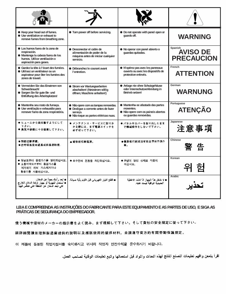
WARNING
AVISO DEPRECAUCION
ATTENTION
WARNUNG
ATENÇÃO
Spanish
French
German
Portuguese
Japanese
Chinese
Korean
Arabic
LEIA E COMPREENDA AS INSTRUÇÕES DO FABRICANTE PARA ESTE EQUIPAMENTO E AS PARTES DE USO, E SIGA ASPRÁTICAS DE SEGURANÇA DO EMPREGADOR.
● Keep your head out of fumes.● Use ventilation or exhaust to
remove fumes from breathing zone.
● Los humos fuera de la zona derespiración.
● Mantenga la cabeza fuera de loshumos. Utilice ventilación oaspiración para gases.
● Gardez la tête à l’écart des fumées.● Utilisez un ventilateur ou un
aspirateur pour ôter les fumées deszones de travail.
● Vermeiden Sie das Einatmen vonSchweibrauch!
● Sorgen Sie für gute Be- undEntlüftung des Arbeitsplatzes!
● Mantenha seu rosto da fumaça.● Use ventilação e exhaustão para
remover fumo da zona respiratória.
● Turn power off before servicing.
● Desconectar el cable dealimentación de poder de lamáquina antes de iniciar cualquierservicio.
● Débranchez le courant avantl’entretien.
● Strom vor Wartungsarbeitenabschalten! (Netzstrom völligöffnen; Maschine anhalten!)
● Não opere com as tampas removidas.● Desligue a corrente antes de fazer
serviço.● Não toque as partes elétricas nuas.
● Do not operate with panel open orguards off.
● No operar con panel abierto oguardas quitadas.
● N’opérez pas avec les panneauxouverts ou avec les dispositifs deprotection enlevés.
● Anlage nie ohne Schutzgehäuseoder Innenschutzverkleidung inBetrieb setzen!
● Mantenha-se afastado das partesmoventes.
● Não opere com os paineis abertosou guardas removidas.

▲▲▲
▲▲▲
▲▲
▲▲
▲▲▲▲▲▲
▲▲▲
▲▲
▲▲
▲▲▲
WARRANTY
PE
RF
OR
MA N C E P L U S P R O
T EC
TI O
N
LINCO
LN ELECTRIC3YEAR
INCLUDING: PARTS & LABOR
S22127-2
• Sales and Service through Subsidiaries and Distributors Worldwide •
22801 St. Clair Ave. Cleveland, Ohio 44117-1199 U.S.A. Tel. 216-481-8100
World's Leader in Welding and Cutting Products Premier Manufacturer of Industrial Motors
STATEMENT OF WARRANTY:
The Lincoln Electric Company (Lincoln) warrants to theoriginal purchaser (end-user) of new equipment that it willbe free of defects in workmanship and material.
This warranty is void if Lincoln finds that the equipmenthas been subjected to improper care or abnormaloperation.
WARRANTY PERIOD:
All warranty periods date from the date of shipment to theoriginal purchaser and are as follows:
Three Years:Transformer WeldersMotor-generator WeldersInverter WeldersAutomatic Wire FeedersSemiautomatic Wire FeedersPlasma-cutting Power SourceEngine Driven Welders (except engine and engine accessories) with operating speed under 2,000 RPM
Two Years:Engine Driven Welders (except engine, engineaccessories and Power-Arc 4000 generator/welders)with operating speed over 2,000 RPM
All engine and engine accessories are warranted by theengine or engine accessory manufacturer and are notcovered by this warranty.
One Year:Equipment not listed above such as gun and cableassemblies, water coolers, FAS TRAK or MIG-TRAKequipment, Power-Arc 4000 generator/welders, Wire FeedModule (Factory Installed) and field-installed optionalequipment.
TO OBTAIN WARRANTY COVERAGE:
You are required to notify Lincoln Electric, your LincolnDistributor, Lincoln Service Center or Field Service Shop ofany defect within the warranty period. Written notification isrecommended.
WARRANTY REPAIR:
If Lincoln's inspection of the equipment confirms theexistence of a defect covered by this warranty, the defectwill be corrected by repair or replacement at Lincoln'soption.
WARRANTY COSTS:
You must bear the cost of shipping the equipment to aLincoln Service Center or Field Service Shop as well asreturn shipment to you from that location.
IMPORTANT WARRANTY LIMITATIONS:
• Lincoln will not accept responsibility for repairs madewithout its authorization.
• Lincoln shall not be liable for consequential damages(such as loss of business, etc.) caused by the defect or reasonable delay in correcting the defect.
• Lincoln's liability under this warranty shall not exceedthe cost of correcting the defect.
• This written warranty is the only express warranty provided by Lincoln with respect to its products. Warranties implied by law such as the Warranty ofMerchantability are limited to the duration of thislimited warranty for the equipment involved.
LIMITED WARRANTY
March, ‘96