Embed Size (px)
DESCRIPTION
The slide unit shape can be selected from two types, thestandard type and the wide type suited for single-rowtrack rail uses, and there are four types with differentlengths of slide unit with same section.
Citation preview
7/14/2019 IKO Maintenance Free C-lube Rail
http://slidepdf.com/reader/full/iko-maintenance-free-c-lube-rail 1/17
● Wide range of variations for your needs
The slide unit shape can be selected from two types, the
standard type and the wide type suited for single-row
track rail uses, and there are four types with different
lengths of slide unit with same section. Furthermore, the
track rail has the variation of standard type and tapped rail
type with the screw thread implanted, allowing you to
select an optimal product for the specifications of your
machine and device.
Points
Super small-size linear motion rolling guide produced by
two-row four-point contact simple structure and originalsmall sizing technology. The track rail width of LWL1, the
smallest size, is only 1mm.
● Ball retained type for easy operation
The slide unit of ball retained type incorporates the ball
retaining band, which prevents the ball from dropping
down when the slide unit is removed from the track rail.
This safety structure brings you an easy operation to the
machines / equipment.
Stainless steel highly corrosion-resistant is used as the
basic specification, so that the products are suitable for
applications where rust prevention oil is not preferred,
such as in cleanroom environment. High carbon steel
products suited to general purposes are als o provided.
● Widely supports special environment uses
C-Lube linear way L models for special environment uses are
provided as a series. Increasingly varied special environment
uses are supported, such as by high-speed / low-noise
specifications by combining silicon nitride ceramics and low
dust-generation specifications.
LWL
Linear Way L
ML
C-Lube Linear Way ML
C-Lube Maintenance Free Series
The aquamarine end plate is the
symbol of maintenance free.Long period maintenancefree supported!
● Stainless steel selections for excellent
corrosion resistance
● Extremely small size realized by simple
structure F or d et ai ls P.Ⅰ-19
F or d et ai ls P.Ⅰ-25
F or d et ai ls P.Ⅰ-31
F or d et ai ls P.Ⅰ-41
Slide unit
Casing
C-Lube
Ball
End plate
End seal
Ball retaining band
Oil hole
Track rail
Ⅱ−6Ⅱ−5
Identification Number and Specification
1N=0.102kgf=0.2248lbs.1mm=0.03937inch
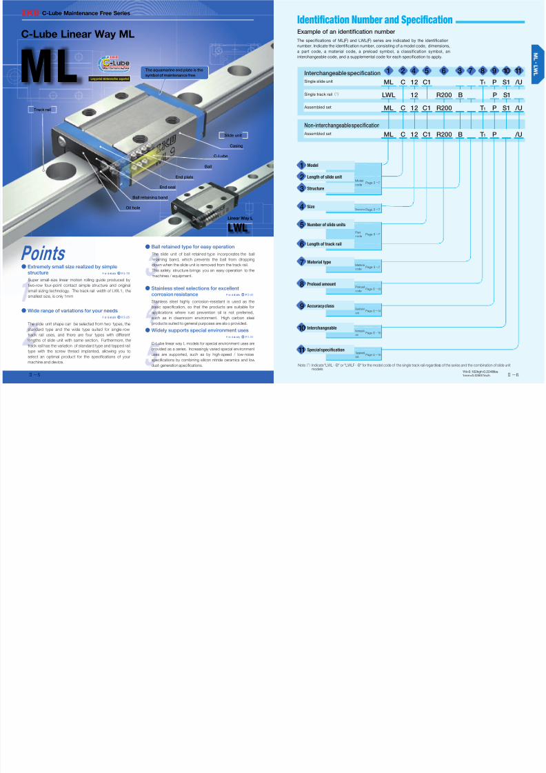
Example of an identification number
The specifications of ML(F) and LWL(F) series are indicated by the identification
number. Indicate the identification number, consisting of a model code, dimensions,
a part code, a material code, a preload symbol, a classification symbol, an
interchangeable code, and a supplemental code for each specification to apply.
Interchangeable specification 1 2 4 5 6 3 7 8 9 10 11
Single slide unit ML C 12 C1 T1 P S1 /U
Single track rail(1
) LWL 12 R200 B P S1
Assembled set ML C 12 C1 R200 T1 P S1 /U
Non-interchangeable specification
Assembled set ML C 12 C1 R200 B T1 P /U
Model
1
Length of slide unit
2Model
codePageⅡ−7
Structure
3
Size
4DimensionsPageⅡ−7
Number of slide units
5Part
codePageⅡ−7
Length of track rail
6
Material type
7Material
codePageⅡ−7
Preload amount
8 Preload
codePage Ⅱ−13
Accuracy class
9Classification
codePage Ⅱ−14
Interchangeable
10Interchangeable
codePage Ⅱ−15
Special specification
11Supplemental
codePage Ⅱ−15
Note(1) Indicate "LWL…B" or "LWLF…B" for the model code of the single track rail regardless of the series and the combination of slide unitmodels.

7/14/2019 IKO Maintenance Free C-lube Rail
http://slidepdf.com/reader/full/iko-maintenance-free-c-lube-rail 2/17
Ⅱ−7 Ⅱ−8
Number of Slide Unit・Length of Track Rail・Material Type ーDetails of Identification Number and Specification ーModel・Length of Slide Unit・Structure・Size
1N=0.102kgf=0.2248lbs.1mm=0.03937inch
C-Lube Linear Way ML
(ML(F) series)
Standard type
Wide type
:ML
:MLF
Linear way L(1)
(LWL(F)series)
Standard type
Wide type
:LWL
:LWLF
For applicable models and sizes, see Table 2.1 and Table 2.2.
Indicate "LWL…B" or "LWLF…B" for the model code of the single track rail regardless of the
series and the combination of slide unit models.
Note(1) This model has no built-in C-Lube.
Short
StandardLong
Extra long
:C
:No symbol
:G
:L
For applicable models and sizes, see Table 2.1 and
Table 2.2.
For applicable models and sizes, see Table 2.1 and Table 2.2.
Standard type 1, 2, 3, 5, 7, 9, 12,
15, 20, 25
Wide type 4, 6, 10, 14, 18, 24,
30, 42
For applicable models and sizes, see Table 2.1 and
Table 2.2.
:C○ For an assembled set, indicates the number of slide
units assembled on a track rail. For a single slide unit,
only "C1" is specified.
:R○ Indicate the length of track rail in mm.
For standard and maximum lengths, see Table 3.1,
Table 3.2, and Table 3.3.
Stainless steel made
High carbon steel made
:No symbol
:CS
For applicable models and sizes, see Table 2.1 and
Table 2.2.
Model1
Length of slide unit2
Structure3 Table 1.1 Structure of ML and LWL
Model Types and sizes of track rails Structure
ML Standard rail specification Ball retained type :No symbol
LWL
Standard rail specification Ball retained type :B
Tapped railspecification
Mounting
from bottom
Size: 2, 3 Ball non-retained type :No symbol
Size: 5, 7, 9 Ball retained type :N
Mounting
from lateralSize: 1
Ball non-
retained type:Y
Solid rail
specificationSize: 1
Ball non-retained type
:No symbol
Table 1.2 Structure of MLF and LWLF
Model Types of track rails Structure
MLF Standard rail specification Ball retained type :No symbol
LWLF
Standard rail specificationSize: 4, 6 Ball non-retained type :No symbol
Size: 10∼42 Ball retained type :B
Tapped rail specificationSize: 6 Ball non-retained type
:NSize: 10∼18 Ball retained type
Size4
Number of slide units5
Length of track rail6
Material type7
Table 2.1 Models and sizes of standard type ML(F) and LWL(F) series
Types of track railsMaterial
typeLength of slide unit Structure Model
Size
1 2 3 5 7 9 12 15 20 25
S t a i n l e s s s t e e l m a d e
Ball retained
type
MLC − − − ○ ○ ○ ○ ○ ○ ○
LWLC…B − − − ○ ○ ○ ○ ○ ○ ○
ML − − − ○ ○ ○ ○ ○ ○ ○
LWL…B − − − ○ ○ ○ ○ ○ ○ ○
MLG − − − − ○ ○ ○ ○ ○ ○
LWLG…B − − − − ○ ○ ○ ○ ○ ○
MLL − − − − − ○ ○ ○ − −
H i g h c a r b o n
s t e e l m a d e
LWL…BCS − − − − − ○ ○ ○ ○ −
S t a i n l e s s s t e e l m a d e
Ball non-retained type
LWLC − − ○ − − − − − − −
Ball retainedtype
LWLC…N − − − ○ ○ ○ − − − −
Ball non-retained type
LWL − ○ ○ − − − − − − −
Ball retainedtype
LWL…N − − − ○ ○ ○ − − − −
Ball retainedtype
LWLG…N − − − − ○ ○ − − − −
Ball non-retained type
LWL… Y ○ − − − − − − − − −
Ball non-retained type
LWL ○ − − − − − − − − −
Remark: For the models indicated in , the interchangeable specification is available.
Standard rail specification
Short
Standard
Long
Extra long
Standard
Tapped rail specificationMounting from bottom
Short
Standard
Long
Tapped rail specificationMounting from lateral
Standard
Solid rail specification
Standard

7/14/2019 IKO Maintenance Free C-lube Rail
http://slidepdf.com/reader/full/iko-maintenance-free-c-lube-rail 3/17
Ⅱ−9 Ⅱ−10
ー Model・Length of Slide Unit・Structure・Size・Material Type ー ー Length of Track Rail ー
1N=0.102kgf=0.2248lbs.1mm=0.03937inch
Table 3.1 Standard and maximum length of stainless steel track rail (Standard type)
unit: mm
Identificationnumber
ItemLWL1… Y LWL1 LWL2 LWL3
ML 5
LWL 5…B
ML 7
LWL 7…B
Standard length L(n)
18( 3)
30( 5)
42( 7)
18(−)
30(−)
42(−)
32( 4)
40( 5)
56( 7)
80(10)
30( 3)
40( 4)
60( 6)
80( 8)
100(
10)
60( 4)
90( 6)
105( 7)
120( 8)
150(
10)
60( 4)
90( 6)
120( 8)
150(10)
180(
12)
240(16)
Pitch of mounting holes F 6 − 8 10 15 15
E 3 − 4 5 7.5 7.5
E referencedimensions(1)
or higher 2.5 − 2.5 3 4 4.5
below 5.5 − 6.5 8 11.5 12
Maximum length(2)102 102 104
(200)
150(300)
210(510)
300(990)
Maximum number ofbutt-jointing track rail(3)
− − − − 5 7
Maximum length ofbutt-jointing track rail(3)
− − − − 915 1 905
Identificationnumber
Item
ML 9
LWL 9…B
ML 12
LWL 12…B
ML 15
LWL 15…B
ML 20
LWL 20…B
ML 25
LWL 25…B
Standard length L(n)
60( 3)
80( 4)
120( 6)
160( 8)
220(11)
280(14)
100( 4)
150( 6)
200( 8)
275(11)
350(14)
475(19)
160( 4)
240( 6)
320( 8)
440(11)
560(14)
680(17)
180( 3)
240( 4)
360( 6)
480( 8)
660(11)
840(14)
240( 4)
300( 5)
360( 6)
480( 8)
660(11)
900(15)Pitch of mounting holes F 20 25 40 60 60
E 10 12.5 20 30 30
E reference
dimensions(1)
or higher 4.5 5 5.5 8 9
below 14.5 17.5 25.5 38 39
Maximum length(2)860
(1 200)
1 000(1 450)
1 000(1 480)
960(1 800)
960(1 800)
Maximum number of
butt-jointing track rail(3)2 2 2 2 2
Maximum length of
butt-jointing track rail(3)1 660 1 925 1 880 1 740 1 740
Notes(1)Not applicable to track rail with stopper pins (supplemental code "/S").
(2)Length up to the value in ( ) can be produced. If needed, please contact あ . Not applicable to tapped rail specifications.
(3)Not applicable to interchangeable specifications or tapped rail specifications.
Remarks 1. A typical identification number is indicated, but is applied to all models of the same size.
2. Indicate "LWL…B" for the model code of the single track rail regardless of the series and the combination of slide unit models.
3. If not directed, E dimensions for both ends will be the same within the range of E reference dimensions. To change the dimensions,
indicate the specified rail mounting hole positions "/E" of special specification. For more information, see page III-29.
n (Pieces)
L
E E F
LWL1…Y
LWL1
n (Pieces)
E F
L
E
L
Table 2.2 Models and sizes of wide type ML(F) and LWL(F) series
Types of track railsMaterial
typeLength of slide unit Structure Model
Size
4 6 10 14 18 24 30 42
S t a i n l e s s s t e e l m a d e
Ball retainedtype
MLFC − − ○ ○ ○ ○ ○ ○
LWLFC…B − − ○ ○ ○ ○ ○ ○
Ball non-retained type
LWLFC − ○ − − − − − −
Ball retainedtype
MLF − − ○ ○ ○ ○ ○ ○
LWLF…B − − ○ ○ ○ ○ ○ ○
Ball non-retained type
LWLF ○ ○ − − − − − −
Ball retainedtype
MLFG − − − ○ ○ ○ ○ ○
LWLFG…B − − − ○ ○ ○ ○ ○
H i g h c a r b o n
s t e e l m a d e
Ball retainedtype
LWLF…BCS − − − − ○ ○ ○ ○
S t a i n l e s s s t e e l m a d e
Ball retainedtype
LWLFC…N
− − ○ ○ ○ − − −
Ball non-retained type
− ○ − − − − − −
Ball retainedtype
LWLF…N
− − ○ ○ ○ − − −
Ball non-retained type
− ○ − − − − − −
Ball retainedtype
LWLFG…N − − − ○ ○ − − −
Remark: For the models indicated in , the interchangeable specification is available.
Standard rail specification
Short
Standard
Long
Standard
Tapped rail specificationMounting from bottom
Short
Standard
Long

7/14/2019 IKO Maintenance Free C-lube Rail
http://slidepdf.com/reader/full/iko-maintenance-free-c-lube-rail 4/17
Ⅱ−11 Ⅱ−12
ー Length of Track Railーー Length of Track Railー
1N=0.102kgf=0.2248lbs.1mm=0.03937inch
Table 3.3 Standard and maximum length of high carbon steel track rail (Standard type, Wide type)
unit: mm
Identificationnumber
ItemLWL 9…BCS LWL12…BCS LWL15…BCS LWL20…BCS
Standard length L(n)
80( 4)160( 8)
220(11)
280(14)
380(19)
500(25)
600(30)
100( 4)200( 8)
275(11)
350(14)
475(19)
600(24)
700(28)
160( 4)320( 8)
440(11)
560(14)
680(17)
800(20)
920(23)
180( 3)240( 4)
360( 6)
480( 8)
660(11)
900(15)
1 020(17)
Pitch of mounting holes F 20 25 40 60
E 10 12.5 20 30
E referencedimensions(1)
or higher 4.5 5 5.5 8
below 14.5 17.5 25.5 38
Maximum length 1 000 1 500 1 520 1 560
Identificationnumber
Item
LWLF18…BCS LWLF24…BCS LWLF30…BCS LWLF42…BCS
Standard length L(n)
90( 3)
180( 6)
240( 8)
300(10)
420(14)
510(17)600(20)
120( 3)
240( 6)
320( 8)
400(10)
600(15)
720(18)800(20)
160( 4)
320( 8)
440(11)
560(14)
680(17)
800(20)920(23)
160( 4)
320( 8)
440(11)
560(14)
680(17)
800(20)920(23)
Pitch of mounting holes F 30 40 40 40
E 15 20 20 20
E referencedimensions(1)
or higher 5.5 6.5 6.5 6.5
below 20.5 26.5 26.5 26.5
Maximum length 1 500 1 520 1 600 1 600
Note(1)Not applicable to track rail with stopper pins (supplemental code "/S").
Remarks 1. A typical identification number is indicated, but is applied to all models of the same size.
2. If not directed, E dimensions for both ends will be the same within the range of E reference dimensions. To change the dimensions,
indicate the specified rail mounting hole positions "/E" of special specification. For more information, see page III-29.
n(Pieces)
L
E E F
LWLF 42…BCSLWLF…BCSLWL…BCS
n(Pieces) 2×n(Pieces)
Table 3.2 Standard and maximum length of stainless steel track rail (Wide type)
unit: mm
Identificationnumber
ItemLWLF4 LWLF6
MLF 10
LWLF 10…B
MLF 14
LWLF 14…B
Standard length L(n)
40( 4)60( 6)
70( 7)
80( 8)
100(10)
60( 4)90( 6)
105( 7)
120( 8)
150(10)
60( 3)80( 4)
120( 6)
160( 8)
220(11)
280(14)
90( 3)120( 4)
150( 5)
180( 6)
240( 8)
300(10)
Pitch of mounting holes F 10 15 20 30
E 5 7.5 10 15
E reference
dimensions(1)
or higher 3.5 4.5 4.5 5.5
below 8.5 12 14.5 20.5
Maximum length(2)180
(300)
240(300)
300(500)
300(990)
Maximum number of
butt-jointing track rail(3)− − 7 8
Maximum length ofbutt-jointing track rail(3)
− − 1 840 1 950
Identificationnumber
Item
MLF 18
LWLF 18…B
MLF 24
LWLF 24…B
MLF 30
LWLF 30…B
MLF 42
LWLF 42…B
Standard length L(n)
90( 3)
120( 4)150( 5)
180( 6)
240( 8)
300(10)
120( 3)
160( 4)240( 6)
320( 8)
400(10)
480(12)
160( 4)
240( 6)320( 8)
440(11)
560(14)
680(17)
160( 4)
240( 6)320( 8)
440(11)
560(14)
680(17)
Pitch of mounting holes F 30 40 40 40
E 15 20 20 20
E referencedimensions(1)
or higher 5.5 6.5 6.5 6.5
below 20.5 26.5 26.5 26.5
Maximum length(2)690
(1 860)
680
(1 960)
680
(2 000)
680
(2 000)
Maximum number of
butt-jointing track rail(3)3 3 3 3
Maximum length of
butt-jointing track rail(3)1 920 1 840 1 840 1 840
Notes(1)Not applicable to track rail with stopper pins (supplemental code "/S").
(2) Length up to the value in ( ) can be produced. If needed, please contactあ . Not applicable to tapped rail specifications.
(3)Not applicable to interchangeable specifications or tapped rail specifications.
Remarks 1. A typical identification number is indicated, but is applied to all models of the same size.
2. Indicate "LWLF…B" for the model code of the single track rail regardless of the series and the combination of slide unit models.
3. If not directed, E dimensions for both ends will be the same within the range of E reference dimensions. To change the dimensions,indicate the specified rail mounting hole positions "/E" of special specification. For more information, see page III-29.
LWLF 42…B
n(Pieces) 2×n(Pieces)
L
E E F

7/14/2019 IKO Maintenance Free C-lube Rail
http://slidepdf.com/reader/full/iko-maintenance-free-c-lube-rail 5/17Ⅱ−13 Ⅱ−14
ー Accuracy class ーー Preload Amountー
1N=0.102kgf=0.2248lbs.1mm=0.03937inch
High
Precision
:H
:P
For interchangeable specification products, assemble a
slide unit and a track rail of the same accuracy class.
Size 1 series have "No symbols."
For the details of accuracy class, see Table 6.1 and 6.2.
Accuracy class9Clearance
Standard
Light preload
:T0
:No symbol
:T1
Specify this item for an assembled set or a single slide
unit.
For details of the preload amount, see Table 4.
For applicable preload types, see Table 5.1 and Table
5.2.
Preload amount8
Table 4 Preload amount
Item
Preloadtype
Preloadsymbol
Preloadamount
NOperational conditions
Clearance T0 0(1) ・ Very light motion
Standard (No symbol) 0(2) ・Light and precise motion
Light preload T1 0.02 C 0
・ Almost no vibrations・Load is evenly balanced・Light and precise motion
Notes(1) There is zero or subtle clearance.
(2)Indicates zero or minimal amount of preload.
Remark: C 0indicates the basic static load rating.
Table 5.1 Application of preload (Standard type)
Size
Preload type(preload symbol)
C learance St andard Li ght prelo ad
(T0) (No symbol) (T1)
1 ○ − −
2 ○ − −
3 ○ − −
5 ○ ○ −
7 ○(1) ○ ○(1)
9 ○(1
) ○ ○(1
)12 ○(1) ○ ○(1)
15 ○(1) ○ ○(1)
20 ○ ○ ○
25 ○ ○ ○
Note(1)Not applicable when /HB is specified.
Remark: The mark indicates that interchangeable
specification products are available.
Table 5.2 Application of preload (Wide type)
Size
Preload type(preload symbol)
Cle arance Standard Light p rel oad
(T0) (No symbol) (T1)
4 ○ − −
6 ○ − −
10 ○ ○ −
14 ○ ○ ○
18 ○ ○ ○
24 ○ ○ ○30 ○ ○ ○
42 ○ ○ ○
Remark: The mark indicates that interchangeable specification
products are available.
Table 6.1 Tolerance and allowable values (Series of size 1)
unit: mm
Item Tolerance
Dim. H tolerance ±0.020
Dim. N 1and Dim. N
2tolerance ±0.025
H
N 1
N 2
C
A
BD1 D2
Fig. 1 Para llelism during running (Series of size 2 or higher)
0
10
20
30
0 500 15001000 2000
P r e c i s i o n(
P )
H i g h(
H )
Length of track rail L mm
P a r a l l e l i s m μ
m
Table 6.2 Tolerance and allowance (Series of size 2 or higher)
unit: mm
Class(classificationsymbol)
Item
High Precision
(H) (P)
Dim. H tolerance ±0.020 ±0.010
Dim. N tolerance ±0.025 ±0.015
Dim. variation of H (1) 0.015 0.007
Dim. variation of N (1) 0.020 0.010
Dim. variation of H formultiple assembled sets(2)
0.030 0.020
Parallelism in operation ofthe slide unit C surface to A
surface
See Fig. 1
Parallelism in operation ofthe slide unit D surface to B
surface
See Fig. 1
Notes(1) It means the size v ariation between slide units mounted
on the same track rail.
(2) Applicable to the interchangeable specification.
N
C
D B
H
A

7/14/2019 IKO Maintenance Free C-lube Rail
http://slidepdf.com/reader/full/iko-maintenance-free-c-lube-rail 6/17Ⅱ−15 Ⅱ−16
ー Special Specificationーー Interchangeable Specification・Special Specificationー
1N=0.102kgf=0.2248lbs.1mm=0.03937inch
S1 specification
S2 specification
Non-interchangeable
specification
:S1
:S2
:No symbol
This is specified for the interchangeable specifications.
Assemble a track rail and a slide unit with the same
interchangeable code. Performance and accuracy of
"S1" and "S2" are the same.
For applicable models and sizes, see Table 2.1 and
Table 2.2.
"No symbol" is indicated for non-interchangeable
specification.
/A, /BS, /D, /E, /HB, / 1, /LR,
/MN, /N, /Q, /RE, /S, /U, /W○, /Y○
For applicable special specifications, see Tables 7.1,
7.2, 7.3, and 7.4.
For combination of multiple special specifications, see
Table 8.For details of special specification, see page Ⅲ-28.
Interchangeable10
Special specification11
Table 7.1 Application of special specifications (Interchangeable specification, single slide unit)
Special specificationSupplemental
code
Size
1 2 3 5 7 9 12 15 20 25
− 4 6 10 14 18 24 30 42 −
No end seal /N − − − ○ ○ ○ ○ ○ ○ ○
With C-Lube plate(1) /Q − − − ○ ○ ○ ○ ○ ○ ○
Under seal /U − − − × × ○ ○ ○ ○ ○
Note(1) Applicable to LWW(F) series.
Table 7.2 Application of special specifications (Interchangeable specification, single track rail)
Special specificationSupplemental
code
Size
1 2 3 5 7 9 12 15 20 25
− 4 6 10 14 18 24 30 42 −
Specified ra il mount ing ho le pos it ions /E − − − ○ ○ ○ ○ ○ ○ ○
Without track rail mounting bolt /MN − − − ○ ○ ○ ○ ○ ○ ○
Table 7.3 Application of special specifications (Interchangeable specification, assembled set)
Special specificationSupplemental
code
Size
1 2 3 5 7 9 12 15 20 25
− 4 6 10 14 18 24 30 42 −
Opposite reference surfaces arrangement /D − − − ○ ○ ○ ○ ○ ○ ○
Specified ra il mount ing ho le pos it ions /E − − − ○ ○ ○ ○ ○ ○ ○
Without track rail mounting bolt(1) /MN − − − ○ ○ ○ ○ ○ ○ ○
No end seal /N − − − ○ ○ ○ ○ ○ ○ ○
With C-Lube plate(2) /Q − − − ○ ○ ○ ○ ○ ○ ○
Under seal /U − − − × × ○ ○ ○ ○ ○
Notes(1)Not applicable to tapped rail specification.
(2) Applicable to LWL(F) series.
Table 7.4 Application of special specifications (Non-interchangeable specification)
Special specificationSupplemental
code
Size
1 2 3 5 7 9 12 15 20 25
− 4 6 10 14 18 24 30 42 −
Butt-jointing track rails(1)(2) /A × × × ○ ○ ○ ○ ○ ○ ○
Stainless steel end plate(3) /BS × ○(5) ○(5) ○ ○ ○ ○ ○ ○ ×
Opposite reference surfaces arrangement /D × ○ ○ ○ ○ ○ ○ ○ ○ ○
Specified ra il mount ing ho le pos it ions /E × ○ ○ ○ ○ ○ ○ ○ ○ ○
Hybrid C-Lube Linear Way /HB × × × × ○(6) ○(6) ○(6) ○(6) × ×
Inspection sheet / 1 × ○ ○ ○ ○ ○ ○ ○ ○ ○
Black chrome surface treatment (track rail) /LR × × × × ○ ○ ○ ○ ○ ○
Without track rail mounting bolt(2) /MN × ○(7) ○(7) ○ ○ ○ ○ ○ ○ ○
No end seal /N × × × ○ ○ ○ ○ ○ ○ ○
With C-Lube plate(3) /Q × × × ○ ○ ○ ○ ○ ○ ○
Special environment seal(3) /RE × × × ○ ○ ○ ○ ○ ○ ×
Track rail with stopper pins /S × × × ○ ○ ○ ○ ○ ○ ○
Under seal /U × × × × × ○ ○ ○ ○ ○
A group of multiple assembled sets /W○ × ○ ○ ○ ○ ○ ○ ○ ○ ○
Specified grease(4) /Y○ × ○(8) ○ ○ ○ ○ ○ ○ ○ ○
Notes(1)Not applicable to high carbon steel made products.
(2)Not applicable to tapped rail specification.
(3) Applicable to LWL(F) series. / YCG is applicable to ML(F) series.
(4)ML(F) series is applicable only to /YCG.
(5)Not applicable to size 4 and 6 series.
(6) Applicable to size 7, 9, 12, and 15 of ML series.
(7)Not applicable to size 2 and 3 series.
(8) Applicable only to /YNG.
Table 8 Combination of supplemental codes
BS○
D ○ ○
E − ○ −
HB ○ − ○ ○
1 ○ ○ ○ ○ ○
LR − ○ ○ ○ ○ ○
MN ○ ○ ○ ○ ○ ○ ○
N ○ ○ ○ ○ ○ ○ ○ ○
Q ○ ○ ○ ○ − ○ ○ ○ ○
RE ○ ○ ○ ○ − ○ ○ ○ − ○
S ○ ○ ○ ○ ○ ○ ○ ○ ○ ○ ○
U ○ ○ ○ ○ ○ ○ ○ ○ − ○ − ○
W ○ ○ ○ − ○ ○ ○ ○ ○ ○ ○ ○ ○
Y ○ ○ ○ ○ − ○ ○ ○ ○ − ○ ○ ○ ○
A BS D E HB 1 LR MN N Q RE S U W
Remarks 1. The combination of " − " shown in the table is not
available.
2. When using multiple types for combination, please
indicate by arranging the symbols in alphabetical
order.

7/14/2019 IKO Maintenance Free C-lube Rail
http://slidepdf.com/reader/full/iko-maintenance-free-c-lube-rail 7/17Ⅱ−17 Ⅱ−18
Lubricationー Special Specificationー Dust Protection
1N=0.102kgf=0.2248lbs.1mm=0.03937inch
Lithium-soap base grease (MULTEMP PS No.2 [KYODO
YUSHI CO., LTD.]) is pre-packed in ML(F) and LWL(F) series.
Add iti ona lly, ML( F) ser ies has C-L ube pla ced in the
recirculation part of balls, so that lubricant replenishment
interval can be extended and maintenance man-hours such
as grease job can be reduced significantly.
ML(F) series and LWL(F) series have grease nipple or oil hole
as indicated in Table 14. Since the Size 1, 2, 3, 4 and 6
series do not have an oil hole, apply grease directly to the
raceway part of the track rail for re-greasing. Supply nozzles
fit to each shapes of grease nipple and dedicated supplying
equipment (miniature greasers) fit to oil holes are also
available. When these parts are desired, refer to Table 14
and Table 15.1 in Ⅲ-22 and Table 16 of page Ⅲ-23 to order.
The slide unit of ML(F) series and LWL(F) series is dust
protected by end seals included as standard. However, if
large amount of contaminant or dust are floating, or if large
particles of foreign substances such as chips or sand may
adhere to the track rail, it is recommended to attach a
protective cover to the linear motion mechanism.
No end seal is provided for size 1, 2, 3, 4 or 6 series. For
applications in the environment not clean enough, cover the
entire unit with a protective case, etc. to prevent harmful
foreign substances such as dust and particles from outside
to enter.
Table 9 Dimensions of slide unit with C-Lube plate (Supplemental code /Q)
unit: mm
Identification
number L
1L
4
Identification
number L
1L
4
LWLC 5…B 22 − LWLFC 10…B 26.5 −
LWL 5…B 25 − LWLF 10…B 30.5 −
LWLC 7…B 27 − LWLFC 14…B 30.5 −
LWL 7…B 31.5 − LWLF 14…B 39.5 −
LWLG 7…B 39 − LWLFG 14…B 50 −
LWLC 9…B 30 − LWLFC 18…B 34.5 −
LWL 9…B 39 − LWLF 18…B 46.5 −
LWLG 9…B 49 − LWLFG 18…B 58.5 −
LWLC 12…B 33 − LWLFC 24…B 38.5 −
LWL 12…B 42 − LWLF 24…B 52 −
LWLG 12…B 52 − LWLFG 24…B 67 −
LWLC 15…B 42 47 LWLFC 30…B 45.5 50
LWL 15…B 52 57 LWLF 30…B 59.5 64
LWLG 15…B 67 72 LWLFG 30…B 78.5 83
LWLC 20…B 48 53 LWLFC 42…B 51.5 56
LWL 20…B 60 65 LWLF 42…B 65 70
LWLG 20…B 78 83 LWLFG 42…B 84.5 89
LWLC 25…
B 63.5 74LWL 25…B 87.5 98
LWLG 25…B 107.5 117
Remarks 1. The dimensions of the slide unit with C-Lube at both
ends are indicated.
2. A typical identification number is indicated, but is
applied to all LWL(F) series models of the same size.
C-Lube C-Lube( L1)
( L4)
Table 11 Dimensions of track rail with stopper pins (Supplemental code /S)
unit: mm
Size a b c
5 − 2 2 1.6
7 −
2.5
2.52
9 − 3
− 10 2 1.6
12 −
3
2
− 14
15 − 4
− 18 3
20 − 5
− 24 3
25 − 3.5 5
− 302.5
4
− 42 5
a
c
b
Table 10 Load rating / static moment rating (Supplemental code /HB) of Hybrid C-Lube Linear Way
Identification
number
C C 0
T 0
T X(1) T
Y(1)
N N N・m N・m N・m
MLC 7… /HB 937 965 3.5 1.612.6
1.310.6
ML 7… /HB 1 330 1 610 5.9 4.023.9
3.320.1
MLG 7… /HB 1 690 2 250 8.2 7.543.1
6.336.2
MLC 9… /HB 1 180 1 260 5.9 2.418.2
2.115.3
ML 9… /HB 1 810 2 340 10.9 7.743.4
6.536.4
MLG 9… /HB 2 370 3 420 15.9 15.983.6 13.470.1
MLL 9… /HB 2 870 4 500 20.9 27.1134
22.7112
MLC 12… /HB 2 210 2 030 12.6 4.535.5
3.829.8
ML 12… /HB 3 330 3 650 22.6 13.179.2
11.066.4
MLG 12… /HB 4 310 5 270 32.7 26.0143
21.9120
MLL 12… /HB 5 820 8 110 50.3 59.3288
49.8242
MLC 15… /HB 3 490 3 310 25.5 9.971.8
8.360.3
ML 15… /HB 4 980 5 520 42.5 25.3146
21.2122
MLG 15… /HB 6 620 8 280 63.7 54.3288
45.5241
MLL 15… /HB 8 370 11 600 89.2 104497
86.9417
Note(1) The upper values of T X
and T Y
are for one slide unit and the
lower values are for two slide units sticking.
Table 12 H 1dimensions with under seal (Supplemental
code /U)
unit: mm
Size H 1
9 − 1
12 − 2
15 − 3
− 18 2
20 − 4
− 24 2
25 − 5(1)
− 30 2
− 42 3
Note(1) The dimensions are the same as those before mounting of
under seal.
H 1
Table 13 Oil hole specifications
unit: mm
Size d 1
d 2
5 10
0.5
1.1
7 14 1.2
9 18 1.5
12 24 2
d 1
d 2
End seal
Rubber part of end seal End plate
Casing
Table 14 Parts for lubrication
Size Grease nipple type(1) Applicable supply nozzle
type
Bolt size of female threads
for piping
5, 7, 9, 12 10, 14, 18, 24 Oil hole Miniature greaser−
15, 20 30, 42 A-M3 A-5120V A-5240V
B-5120V B-5240V
25 − B-M4 A-8120VB-8120V
M4
Note(1)For specifications of grease nipple, see Table 15.1 on page Ⅲ-22.

7/14/2019 IKO Maintenance Free C-lube Rail
http://slidepdf.com/reader/full/iko-maintenance-free-c-lube-rail 8/17Ⅱ−19 Ⅱ−20
Precaution for Use
1N=0.102kgf=0.2248lbs.1mm=0.03937inch
❶Mounting surface, reference mounting surface and
general mounting structure
When mounting the ML(F) series and LWL(F) series, properly
align the reference mounting surfaces B and D (D1 or D2)of
the track rail and slide unit with the reference mounting
surface of the table and bed before fixing them. (See Fig. 2)
Reference mounting surfaces B and D (D1 or D2) and
mounting surfaces A and C are precisely ground. By
machining the mounting surface of the mating member,
such as machine or device, to high accuracy and mounting
them properly, stable linear motion with high accuracy is
obtained.
Reference mounting surface of the slide unit of size 2 orhigher is the opposite side of the あ mark. The track rail
reference mounting surface is identified by locating the
あ mark on the top surface of the track rail. It is the side
surface above the mark (in the direction of the arrow). (See
Fig. 5.2)
Reference mounting surface of the slide unit of size 1 is
located at both right and left sides (D1 and D2). (See Fig.
5.1)
The track rail of LWL1…Y has the mounting structure of
lateral direction. Two types of mounting structure as shown
in Fig. 3.1 and Fig. 3.2 are available.
Fig. 2 Reference mounting surface and typical mounting structure
C
D2
B
A
Fig. 3.1 Reference mounting surface of LWL1 … Y and typical mounting structure ①
D
C
A
B
Fig. 3.2 Reference mounting surface of LWL1 … Y and typical mounting structure ②
D
C
A
B
Fig. 4 Reference mounting surface of size 2, 3, 4 and 6 series and typical mounting structure
Track rail Slide unitReferencemounting surface
Mark
BD1
D2
Fig. 5.1 Reference mounting surface of series size 1 or higher
Fig. 5.2 Reference mounting surface of series size 2 or higher
D1
C
A
B
Track rail Slide unit
Mark Mark
Reference mounting surface
BD
❷ Mounting screws for slide unit
To mount a slide unit, tightly fasten the bolt against female
thread of slide unit.
The female thread is created through holes of the slide unit
for size 1 series, and also through holes for the slide unit
and track rail for size 2, 3, 4 and 6 series. When the fixing
thread depth of the mounting screw goes too deep, it can
interfere with the track rail and impact the running accuracy
or product life so that the fixing thread depth should be
within the screwing depth specified in the dimension table.
Also prep are the smal l scre ws ded icat ed to pre cisi on
devices (head diameter 1.8 mm or smaller) for the mounting
bolt of slide unit of size 1.
❸ Mounting screws for track rail
In the size 2 and 3 series and tapped rail specifications,
track rail mounting bolts are not appended. Prepare
mounting bolts whose fixing thread depth is less than H 4
in
dimension table.
❹ Shoulder height and corner radius of the reference
mounting surface
For the opposite corner of the mating reference mounting, it
is recommended to have relieved fillet as indicated in Fig. 6
Recommended value for the shoulder height on the mating
side is indicated in Table 16.
Fig. 6 Corner of the mating reference mounting
❺ Tightening torque for mounting bolts
Typical tightening torques for mounting ML(F) series and
LWL(F) series to the steel mating member material are
indicated in Table 15. When vibration and shock of the
machine or device are large, fluctuating load is large, or
moment load is applied, fix it by using the torque 1.2 to 1.5
times larger than the value indicated in the table as
necessary. If the mating member material is cast iron or
aluminum, reduce the tightening torque depending on the
strength characteristic of the mating member material.
Table 15 Tightening torque for fixing screw
Bolt size
Tightening torque N・m
Stainless steel-
made screw
High carbon steel-
made screw
M1 ×0.25 0.04 −
M1.4×0.3 0.10 −
M1.6×0.35 0.15 −
M2 ×0.4 0.31 −
M2.5×0.45 0.62 −
M3 ×0.5 1.1 1.2
M4 ×0.7 2.5 2.8
M5 ×0.8 5.0 5.6
M6 ×1 8.5 −
Remarks 1. The calculation is based on the tightening torque,
strength division 8.8 and property division A2-70.
2. It is recommended that the tightening torque of slide
unit mounting holes for series size 1 is to be 70 to 80 %
of the values in the table.

7/14/2019 IKO Maintenance Free C-lube Rail
http://slidepdf.com/reader/full/iko-maintenance-free-c-lube-rail 9/17
Ⅱ−21 Ⅱ−22
Mounting BoltPrecaution for Use
1N=0.102kgf=0.2248lbs.1mm=0.03937inch
For LWL(F) series, track rail mounting bolt of slide unit and
tapped rail specification shown in Table 17 and Table 18are
available. If these parts are necessary, please contact あ .
Table 17 Cross-recessed head screw for precision equipment
unit: mm
Bolt sizePitch of
screw d k
k l
(d ) P
M1 0.25 1.8 0.45 3, 4, 5
M1.4(1) 0.3 2.5 0.8 2.5, 3, 4
M1.6(1) 0.35 2.8 0.85 4, 5, 6
M2(1) 0.4 3.5 1 3, 4, 5
Note(1) Based on cross-recessed head screw for precision
equipment (Number 0) in Japan Camera Industry Standard
JCIS 10-70.
Remark: The dimensions are different from the appended track rail
mounting bolts.
lk
d k
Table 16 Shoulder height and corner radius of the reference mounting surface
unit: mm
Identification number
Mo unti ng part of sli de unit Mo unti ng part of track rai l
S ho ul de r he ig ht C or ne r ra di us S ho ul de r h ei ght(1) Corner radius
h1
R1(Maximum) h
2R
2(Maximum)
− LWL 1… Y 1.3 −
2−
− LWL 1 −
− LWL 2 1 0.1 0.5 0.05
− LWL 3 1.2 0.15 0.8 0.1
ML 5 LWL 5…B 2 0.3 0.8 0.2
ML 7 LWL 7…B 2.5 0.2 1.2 0.2
ML 9 LWL 9…B3
0.21.5 0.2
− LWL 9…BCS 0.4
ML 12 LWL 12…B4
0.22.5 0.2
− LWL 12…BCS 0.4
ML 15 LWL 15…B4.5
0.23 0.2
− LWL 15…BCS 0.4
ML 20 LWL 20…B5
0.24 0.2
− LWL 20…BCS 0.4
ML 25 LWL 25…B 6.5 0.7 4 0.7
−
LWLF 4 1.5 0.1 0.8 0.1− LWLF 6 2 0.1 0.8 0.1
M LF 10 LWLF 10…B 2 0.3 1.2 0.2
M LF 14 LWLF 14…B 2.5 0.2 1.2 0.2
M LF 18 LWLF 18…B3
0.22.5 0.2
− LWLF 18…BCS 0.4
M LF 24 LWLF 24…B4
0.22.5 0.2
− LWLF 24…BCS 0.4
M LF 30 LWLF 30…B4.5
0.22.5 0.2
− LWLF 30…BCS 0.4
M LF 42 LWLF 42…B5
0.23 0.2
− LWLF 42…BCS 0.4
Note(1) For models with under seals (supplemental code "/U"), it is recommended to use the values 1mm smaller than the values in the table.
However for the models of size 9 with under seal, 0.8 mm is recommended.
Remark: A typical identification number is indicated, but is applied to all models of the same size.
R 2
R 1
R2
h 2
h 1
R1
Mo unti ng pa rt of sl id e unit Mo unti ng pa rt of tr ac k r ai l
Table 18 Hexagon socket head bolt
unit: mm
Bolt s ize P itch of screwd
kk s t l
(d ) P
M1.4 0.3 2.6 1.4 1.3 0.6 2.5, 3, 4
M1.6(1) 0.35 3 1.6 1.5 0.7 4, 5, 6
M2(1) 0.4 3.8 2 1.5 1 3, 4, 5
Note(1)Based on hexagon socket head bolts equivalent to JIS B 1176.
lk
d k
t
s

7/14/2019 IKO Maintenance Free C-lube Rail
http://slidepdf.com/reader/full/iko-maintenance-free-c-lube-rail 10/17
C-Lube Linear Way ML
Ⅱ−24
Ⅱ−231N=0.102kgf=0.2248lbs.1mm=0.03937inch
Identification number
I n t e r c h a n g e a b l e Mass (Ref.)
gDimensions of
assemblymm
Dimensions of slide unitmm
Dimensions of track railmm
Appended mountingbolt for track rail(2)
mm
Basic dynamicload rating(5)
Basic staticload rating(5)
Static moment rating(5)
ML seriesLWL series (No C-Lube)
Slideunit
Track rail(per 100 mm)
H H 1
N W 2
L1
L2
L3
M 1×depth H
2W H
4H
5M
2d
3E F Bolt size×R
C
N
C 0
N
T 0
N・m
T X
N・m
T Y
N・m
−
LWL 1…
Y −
0.16 2.1 4.2 2.2 1.5 4 6.5 2 3.9 M1 ×0.9 1.2 1 3.1 1.1
M1.4
Through 1.1 3 6 M1×R
or M1.4×R(3)
66.8 113 0.06 0.070.47
0.090.56
− LWL 1 − 1.0 2.5 0.5 1.4 − − − − − −
− LWL 2 − 0.9 2.8 3.2 0.7 2 6 12.5 4 8.8 M1.4×1.1 − 2 2 −M1
Through− 4 8 M1 ×R(4) 211 381 0.42 0.54
2.90.643.5
− LWLC 3 − 1.05.3 4 1 2.5 8
11.5 3.5 6.7 M1.6×1.3− 3 2.6 −
M1.6Through
− 5 10 M1.6×R(4)251 361 0.58 0.39
2.70.473.2
− LWL 3 − 1.6 15.5 5.5 10.7 M2 ×1.3 353 587 0.94 0.985.6
1.26.7
Notes(1) Track rail lengths L are shown in Table 3.1 on page Ⅱ-10.(2) Track rail mounting bolts are not appended.
(3)Prepare screws according to mounting structure.(4)Choose screws whose dimension allow fixing thread depth into t rack rail R to be less than H
4.
(5) The direction of basic dynamic load rating (C ), basic static load rating (C 0 ), and static moment rating (T
0, T
X, T
Y ) are shown in the
sketches below.
The upper values of T X
and T Y
are for one slide unit and t he lower values are for two slide units sticking.
Remarks 1. Metal parts are made of stainless steel.
2. Do not disassemble a slide unit from the track rail because steel balls are not retained. No end seal is attached.
3. The specification of small size mounting bolts (M2 and less) are show on page Ⅱ-22. If needed, please contact あ .
Example of identification number of assembled set
Model code
LWL
Dimensions Part code
R80C22
LWLModel
Standard typeLWL… Y
Preload symbol Classificationsymbol Special specification
T0 /DP
Model code
1 12 76543 8
1
Number of slide unit(2)4
Size1, 2, 3
3
Length of track rail(80 mm)5
Special specificationBS, D, E,1, MN, W, Y
8
No symbol
Length of slide unit
Standard
2
C Short H
Accuracy class
P Precision
High
7
N o sy mb ol O rd in ar y
Preload amount6
T 0 Clearance
Standard type
Shape
Size1 7532
252015129
LWL
C C 0
T X
T 0
T Y
W 2
W 2
M 2
N
N
W
W
d 3
H
H
H 1
H 1
H 2
H 2
H 4
H 4
H 5
E E F
L(1)
L(1)
( L1)
L3
L2
( L1)
L3
L2
2− M 1×depth
2− M 1×depth
LWL 1…Y
LWL 1
W 2
N W
H
H 1
H 4
E E F
L(1)
( L1)
L3
M 2
L2
2− M 1×depth
LWL 2
LWLC 3
LWL 3

7/14/2019 IKO Maintenance Free C-lube Rail
http://slidepdf.com/reader/full/iko-maintenance-free-c-lube-rail 11/17
Ⅱ−25
C-Lube Linear Way ML
Ⅱ−26
1N=0.102kgf=0.2248lbs.1mm=0.03937inch
Identification number
I n t e r c h a n g e a b l e Mass (Ref.)
gDimensions of
assemblymm
Dimensions of slide unitmm
Dimensions of track railmm
Appended mounting boltfor track rail(2)
mm
Basic dynamicload rating(4)
Basic staticload rating(4)
Static moment rating(4)
ML seriesLWL series (No C-Lube)
Slideunit
Track rail(per 100 mm)
H H 1
N W 2
W 3
W 4
L1
L2
L3
M 1×depth H
3W H
4M
2d
3d
4h E F Bolt size×R
C
N
C 0
N
T 0
N・m
T X
N・m
T Y
N・m
MLC 5 LWLC 5…B ○
3.4
12
6 1 3.5 12 8 2
16
−
9.6
M2×1.5 1.2 5 3.7
− 2.4 3.6 0.8
7.5 15
Cross-recessed headscrew for precision
equipmentM2×6 562 841 2.2 1.4
8.51.27.2
− LWLC 5…N* − 13M2.5Through
− − −M2.5×R(3)
(Not appended)
ML 5 ○ 4.3
12
19 12.6
− 2.4 3.6 0.8
Cross-recessed headscrew for precision
equipmentM2×6 676 1 090 2.9 2.312.8
1.910.8
LWL 5…B ○4.4
− LWL 5…N* − 13M2.5Through
− − −M2.5×R(3)
(Not appended)
MLC 7 ○ 6.722
8 1.5 5 17 12 2.5
19 − 9.6
M2×2.5 1.5 7 5
− 2.4 4.2 2.3
7.5 15
Hexagon socket head boltM2×6
937 1 140 4.1 1.814.9
1.512.5
LWLC 7…B ○
7.1− LWLC 7…N* − 24
M3Through
− − −M3×R(3)
(Not appended)
ML 7 ○ 9.122
23.5 8 14.3
− 2.4 4.2 2.3Hexagon socket head bolt
M2×61 330 1 890 6.9 4.7
28.23.9
23.6
LWL 7…B ○
10− LWL 7…N* − 24
M3Through
− − −M3×R(3)
(Not appended)
MLG 7 ○ 1322
31 12 21.6
− 2.4 4.2 2.3Hexagon socket head bolt
M2×61 690 2 650 9.7 8.8
50.77.4
42.5
LWLG 7…B ○
14− LWLG 7…N* − 24
M3Through
− − −M3×R(3)
(Not appended)
Notes(1) Track rail lengths L are shown in Table 3.1 on page Ⅱ-10.(2)
The appended track rail mounting bolts are hexagon socket head bolts equivalent to JIS B 1176 or cross recessed head screws forprecision equipment.(3) Choose screws whose dimension allow fixing thread depth into t rack rail R to be less than H
4.
(4) The direction of basic dynamic load rating (C ), basic static load rating (C 0 ), and static moment rating (T
0, T
X, T
Y ) are shown in the
sketches below.
The upper values of T X
and T Y
are for one slide unit and t he lower values are for two slide units sticking.
If hybrid C-Lube Linear Way specification (supplemental code "/HB") is selected in MLC7, ML7, and MLG7, s ee Table 10 on pageⅡ-17.
Remarks 1. The specification of oil hole is shown in Table 13 on page Ⅱ-18.
2. The identification numbers with * are our semi-standard items.
Example of identification number of assembled set
Model code
ML
Dimensions Part code
R120C27C
MLModel
Standard typeLWL…B
Preload symbol Classificationsymbol Special specification
T1 /DP
Interchangeable code
S1
Model code
1 12 87654 109
1
Number of slide unit(2)5
Size
5, 7
4
Length of track rail(120 mm)6
S1
Interchangeable
S2 S2 specification
S1 specification
No symbol Non-interchangeable specification
9
T 0
Preload amount
No symbol Standard
Clearance
T 1 Light preload
7
Special specification
A, BS, D, E, HB,1, LRMN, N, Q, RE, S, W, Y
10
LWL…N
No symbol
Length of slide unit
Standard
G Long
2
C Short
P
Accuracy class
Precision
8
H High
Standard type
Shape
Size1 7532
252015129
ML ・ LWL
C C 0
T X
T 0
T Y
Tapped rail specificationLWL…N
N
W 4
W 3
W 2
W
H
H 3
H 1
Oil hole
M 2
MLC, ML5
LWLC, LWL5
E F
L(1)
d 3
d 4
( L1) ( L
1)
L3
L2
E
L3
H 4
h
2− M 1×depth 4− M 1×depth
ML7, MLG
LWL7, LWLG

7/14/2019 IKO Maintenance Free C-lube Rail
http://slidepdf.com/reader/full/iko-maintenance-free-c-lube-rail 12/17
Ⅱ−27
C-Lube Linear Way ML
Ⅱ−28
1N=0.102kgf=0.2248lbs.1mm=0.03937inch
Identification number
I n t e r c h a n g e a b l e Mass (Ref.)
gDimensions of
assemblymm
Dimensions of slide unitmm
Dimensions of track railmm
Appendedmounting bolt for
track rail(2)
mm
Basic dynamicload rating(4)
Basic staticload rating(4)
Static moment rating(4)
ML seriesLWL series (No C-Lube)
Slideunit
Track rail(per 100 mm)
H H 1
N W 2
W 3
W 4
L1
L2
L3
M 1×depth H
3W H
4M
2d
3d
4h E F Bolt size×R
C
N
C 0
N
T 0
N・m
T X
N・m
T Y
N・m
MLC 9 LWLC 9…B ○
11
35
10 2 5.5 20 15 2.5
21.5 − 11.9
M3×3 2.2 9 6
− 3.5 6 3.5
10 20
M3×8
1 180 1 480 6.9 2.921.4
2.418.0
− LWLC 9…N* − 37M4
Through− − −
M4×R(3)(Not appended)
ML 9 ○ 18
35
30 10 20.8
− 3.5 6 3.5 M3×8
1 810 2 760 12.8 9.151.1
7.642.9
LWL 9…B ○
19− LWL 9…BCS ○
− LWL 9…N* − 37 M4Through − − − M4×R(
3
)(Not appended)
MLG 9 ○ 2635
40.5 15 30.9
− 3.5 6 3.5 M3×8
2 370 4 030 18.7 18.798.3
15.782.5
LWLG 9…B ○
28− LWLG 9…N* − 37
M4Through
− − −M4×R(3)
(Not appended)
MLL 9 − ○ 34 35 50 26 40.4 − 3.5 6 3.5 M3×8 2 870 5 300 24.6 31.9157
26.7132
MLC 12 LWLC 12…B ○ 22
65 13 3 7.5 27 20 3.5
25 − 13
M3×3.5 2.7 12 8 − 3.5 6.5 4.5 12.5 25 M3×8
2 210 2 380 14.8 5.341.7
4.535.0
ML 12 ○ 34
34 15 21.6 3 330 4 290 26.6 15.493.1
12.978.2
LWL 12…B ○35
− LWL 12…BCS ○
ML G 1 2 ○ 4844 20 32 4 310 6 200 38.4 30.6
16825.7
141LWLG 12…B ○ 51
MLL 12 − ○ 70 59.5 30 47.3 5 820 9 540 59.1 69.8339
58.6285
Notes(1) Track rail lengths L are shown in Table 3.1 on page Ⅱ-10 and Table 3.3 on page Ⅱ-12.(2) The appended track rail mounting bolts are hexagon socket head bolts equivalent to JIS B 1176. For stainless steel model, stainless
steel made bolts are appended.
(3)Choose screws whose dimension allow fixing thread depth into t rack rail R to be less than H 4.
(4) The direction of basic dynamic load rating (C ), basic static load rating (C 0 ), and static moment rating (T
0, T
X, T
Y ) are shown in the
sketches below.
The upper values of T X
and T Y
are for one slide unit and t he lower values are for two slide units sticking.
If hybrid C-Lube Linear Way specification (supplemental code "/HB") is selected in ML series, see Table 10 on page Ⅱ-17.
Remarks 1. The specification of oil hole is shown in Table 13 on page Ⅱ-18.
2. The identification numbers with * are our semi-standard items.
Example of identification number of assembled set
Model code
ML
Dimensions Part code
R160C29G
MLModel
Standard typeLWL…B
Preload symbol Classificationsymbol Special specification
T1 /DP
Interchangeable code
S1
Model code
1 12 87543 109
1
Number of slide unit(2)4
Size9, 12
3
Length of track rail(160 mm)5
S1
Interchangeable
S2 S2 specification
S1 specification
No symbol Non-interchangeable specification
9
Special specification A, BS, D, E, HB,1, LR, MNN, Q, RE, S, U, W, Y
Material code
6
LWL…N
No symbol
Length of slide unit
Standard
G Long
L Extra high rigidity long
2
C Short
No symbol
Material type
CS High carbon steel made
Stainless steel made
6
T 0
Preload amount
No symbol Standard
Clearance
T 1 Light preload
7
P
Accuracy class
Precision
8
H High
10
Standard type
Shape
Size1 7532
252015129
ML ・ LWL
C C 0
T X
T 0
T Y
N
W 4
W 3
W 2
W
H
H 3
H 1
Oil hole
Tapped rail specification
LWL…N
M 2
ML, MLG
LWL, LWLG
MLLMLC
LWLC
L(1)
( L1)
L3
( L1)
L3
L2
( L1)
L3
L2
L2 / 2 L
2 / 2
E
2− M 1×depth
4− M 1×depth
6− M 1×depth
d 4
d 3
E F
H 4
h

7/14/2019 IKO Maintenance Free C-lube Rail
http://slidepdf.com/reader/full/iko-maintenance-free-c-lube-rail 13/17
Ⅱ−29
C-Lube Linear Way ML
Ⅱ−30
1N=0.102kgf=0.2248lbs.1mm=0.03937inch
Identification number
I n t e r c h a n g e a b l e Mass (Ref.)
gDimensions of
assemblymm
Dimensions of slide unitmm
Dimensions of track railmm
Appended mounting boltfor track rail(2)
mm
Basic dynamicload rating(3)
Basic staticload rating(3)
Static moment rating(3)
ML seriesLWL series (No C-Lube)
Slideunit
Track rail(per 100 mm)
H H 1
N W 2
W 3
W 4
L1
L2
L3
L4
M 1×depth H
3W H
4d
3d
4h E F Bolt size×R
C
N
C 0
N
T 0
N・m
T X
N・m
T Y
N・m
MLC 15 ○ 43
107 16 4 8.5 32 25 3.5
32 −17.8
37
M3×4 3.1 15 10 3.5 6.5 4.5 20 40 M3×10
3 490 3 890 30.0 11.784.5
9.870.9
LWLC 15…B ○ 42 17.7
ML 15 ○ 63
42 20
27.9
47 4 980 6 490 50.0 29.7172
24.9144
LWL 15…B ○64 27.8
− LWL 15…BCS ○
ML G 1 5 ○ 9357 25
42.862 6 620 9 740 75.0 63.9
338
53.6
284LWLG 15…B ○ 95 42.7
MLL 15 − ○ 122 72 40 57.7 76 8 370 13 600 105 122585
102491
MLC 20 LWLC 20…B ○ 89
156 20 5 10 40 30 5
38 − 22.3 43
M4×6 4.2 20 11 6 9.5 5.5 30 60 M5×14
4 580 5 300 54.0 19.4134
16.3112
ML 20 ○ 130
50 25 34.6 55 6 650 9 080 92.6 52.7280
44.2235
LWL 20…B ○133
− LWL 20…BCS ○
ML G 2 0 ○ 18968 30 52.3 73 8 510 12 900 131 102
52985.7
444LWLG 20…B ○ 196
MLC 25 ○ 189
243 25 5 12.5 48 35 6.5
54.5 − 31.9 64
M6×7 5 23 15 7 11.0 9.0 30 60 M6×16
9 120 10 600 128 57.4376
48.1316
LWLC 25…B ○ 190
ML 25 ○ 30578 35 55.7 88 13 500 18 500 223 163
887137744
LWL 25…B ○ 310
MLG 25 ○ 40598 40 75.5 108 16 700 25 200 303 293
1 480246
1 240LWLG 25…B ○ 413
Notes(1) Track rail lengths L are shown in Table 3.1 on page Ⅱ-10 and Table 3.3 on page Ⅱ-12.
(2) The appended track rail mounting bolts are hexagon socket head bolts equivalent to JIS B 1176. For stainless steel model, stainlesssteel made bolts are appended.
(3) The direction of basic dynamic load rating (C ), basic static load rating (C 0 ), and static moment rating (T
0, T
X, T
Y ) are shown in the
sketches below.
The upper values of T X
and T Y
are for one slide unit and t he lower values are for two slide units sticking.
If hybrid C-Lube Linear Way specification (supplemental code "/HB") is selected in MLC15, ML15, MLG15, and MLL15, see Table
10 on page Ⅱ-17.
(4) The shapes of grease nipple vary by size. The specifications are shown in Table 14 on page Ⅱ̶ 18.
Example of identification number of assembled set
Model code
ML
Dimensions Part code
R320C215G
MLModel
Standard typeLWL…B
Preload symbol Classificationsymbol Special specification
/DP
Interchangeable code
S1
Model code
1 12 87543 109
1
Number of slide unit(2)4
Size15, 20, 25
3
Length of track rail(320 mm)5
S1
Interchangeable
S2 S2 specification
S1 specification
No symbol Non-interchangeable specification
9
Special specification A, BS, D, E, HB, 1, LR, MNN, Q, RE, S, U, W, Y
10
Material code
6
No symbol
Length of slide unit
Standard
G Long
L Extra high rigidity long
2
C Short
No symbol
Material type
CS High carbon steel made
Stainless steel made
6
T 0
Preload amount
No symbol Standard
Clearance
T 1 Light preload
7
P
Accuracy class
Precision
8
H High
T1
Standard type
Shape
Size1 7532
252015129
ML ・ LWL
C C 0
T X
T 0
T Y
N
W 4
W 3
W 2
W
H
H 3
H 1
MLC
LWLC
ML, MLG
LWL, LWLG
L(1)
E
2− M 1×depth 6− M 1×depthGrease nipple(4)
4− M 1×depth
MLL
L2 / 2 L2
/ 2
( L4)
( L1)
E F
d 3
d 4
H 4
h
L3
( L4)
( L1)
L3
L2
( L4)
( L1)
L3
L2

7/14/2019 IKO Maintenance Free C-lube Rail
http://slidepdf.com/reader/full/iko-maintenance-free-c-lube-rail 14/17
Ⅱ−31
C-Lube Linear Way ML
Ⅱ−32
1N=0.102kgf=0.2248lbs.1mm=0.03937inch
Identification number
I n t e r c h a n g e a b l e Mass (Ref.)
gDimensions of
assemblymm
Dimensions of slide unitmm
Dimensions of track railmm
Appended mounting boltfor track rail
mm
Basic dynamicload rating(4)
Basic staticload rating(4)
Static moment rating(4)
MLF seriesLWLF series (No C-Lube)
Slideunit
Track rail(per 100 mm)
H H 1
N W 2
W 3
W 4
L1
L2
L3
M 1×depth H
3W H
4M
2d
3d
4h E F Bolt size×R
C
N
C 0
N
T 0
N・m
T X
N・m
T Y
N・m
− LWLF 4(2) − 2.1 6.8 4 1 3 10 − 5 17 6.5 11.9 M2 × 1.3 − 4 2.6 − 1.8 2.8 0.75 5 10Cross-recessed head screw
for precision equipmentM1.6×5
390 677 1.4 1.37.1
1.58.4
− LWLFC 6(2) −
2.4
13
4.5 1 3 12 − 6
15 4.5 9.8
M2 × 1.6 − 6 2.8
− 2.4 4 1.5
7.5 15
Cross-recessed head screwfor precision equipment
M2×4 334 542 1.7 0.845.1
1.06.1
− LWLFC 6…N(2)* − 12
M3Through
− − −M3×R(3)
(Not appended)
− LWLF 6(2) −
3.4
13
20 8 14.6
− 2.4 4 1.5Cross-recessed head screw
for precision equipmentM2×4 443 813 2.5 1.8
9.92.2
11.8
− LWLF 6…N(2)* − 12
M3Through
− − −M3×R(3)
(Not appended)
MLFC 10 ○ 6.128
6.5 1.5 3.5 17 13 2
20.5
−
13.6
M2.5×1.5 1.3 10 4
− 2.9 4.8 1.6
10 20
Cross-recessed head screwfor precision equipment
M2.5×7 712 1 180 6.1 2.614.9
2.212.5
LWLFC 10…B ○
5.9− LWLFC 10…N* − 29
M3Through
− − −M3×R(3)
(Not appended)
MLF 10 ○ 7.628
24.5 17.6
− 2.9 4.8 1.6Cross-recessed head screw
for precision equipmentM2.5×7 849 1 510 7.8 4.2
22.43.5
18.8
LW LF 10…B ○
7.5− LWLF 10…N* − 29
M3Through
− − −M3×R(3)
(Not appended)
Notes(1) Track rail lengths L are shown in Table 3.2 on page Ⅱ-11.(2) Size 4 and 6 are non-retained-ball type. No end seal is attached.
(3)Choose screws whose dimension allow fixing thread depth into t rack rail R to be less than H 4.
(4) The direction of basic dynamic load rating (C ), basic static load rating (C 0 ), and static moment rating (T
0, T
X, T
Y ) are shown in the
sketches below.
The upper values of T X and T
Y are for one slide unit and t he lower values are for two slide units sticking.(5) No oil hole is prepared for size 4 and 6.
The specification of oil hole for size 10 is shown in Table 13 on pageⅡ-18.
Remark: The identification numbers with * are our semi-standard items.
Example of identification number of assembled setExample of identification number of assembled set
Model code
MLF
Dimensions Part code
R120C210
MLFModel
Wide typeLWLF(…B)
Preload symbol Classificationsymbol Special specification
T0 /DP
Model code
1 12 76543 9
1
Number of slide unit(2)4
Size
4, 6, 10
3
Length of track rail(120 mm)5
No symbol
Length of slide unit
Standard
2
C Short
LWLF…N
C
Interchangeable code
S1
8
S1
Interchangeable
S2 S2 specification
S1 specification
No symbol Non-interchangeable specification
8
T 0
Preload amount
No symbol Standard
Clearance
6
P
Accuracy class
Precision
7
H High
Special specification A, BS, D, E,1, MN, N, QRE, S, W, Y
9
Wide type
Shape
Size4 14106
302418 42
MLF ・ LWLF
C C 0
T X
T 0
T Y
W 2
W 3
W 4
W N
H 3
H
H 1
Oil hole(5)
( L1)
L3
( L1)
L3
F E
L2
MLFC10, MLF10
LWLFC10, LWLF10 E
2− M 1×depth
L(1)
d 4
d 3
H 4
h
2− M 1×depth
LWLF4
LWLFC6 , LWLF6 Tapped rail specification
LWLF…N
M 2

7/14/2019 IKO Maintenance Free C-lube Rail
http://slidepdf.com/reader/full/iko-maintenance-free-c-lube-rail 15/17
Ⅱ−33
C-Lube Linear Way ML
Ⅱ−34
1N=0.102kgf=0.2248lbs.1mm=0.03937inch
Identification number
I n t e r c h a n g e a b l e Mass (Ref.)
gDimensions of
assemblymm
Dimensions of slide unitmm
Dimensions of track railmm
Appended mounting boltfor track rail(2)
mm
Basic dynamicload rating(4)
Basic staticload rating(4)
Static moment rating(4)
MLF seriesLWLF series (No C-Lube)
Slideunit
Track rail(per 100 mm)
H H 1
N W 2
W 3
W 4
L1
L2
L3
M 1×depth H
3W H
4M
2d
3d
4h E F Bolt size×R
C
N
C 0
N
T 0
N・m
T X
N・m
T Y
N・m
MLFC 14 LWLFC 14…B ○
13
54
9 2 5.5 25 19 3
22.5 − 13
M3×3 1.7 14 5.5
− 3.5 6 3.2
15 30
M3×8
1 240 1 700 12.23.8
24.63.2
20.7− LWLFC 14…N* − 56
M4Through
− − −M4×R(3)
(Not appended)
MLF 14 ○ 2054
31.5 10 22
− 3.5 6 3.2 M3×8
1 770 2 840 20.310.154.7
8.445.9
LWL F 1 4…B ○
21− LWL F 1 4…N* − 56
M4Through
− − −M4×R(3)
(Not appended)
MLFG 14 ○ 2954
42 19 32.5
− 3.5 6 3.2 M3×8
2 320 4 160 29.821.0
10417.687.6
LWLFG 14…B ○
31− LWLFG 14…N* − 56
M4Through
− − −M4×R(3)
(Not appended)
Notes(1) Track rail lengths L are shown in Table 3.2 on page Ⅱ-11.
(2) The appended track rail mounting bolts are hexagon socket head bolts equivalent to JIS B 1176.(3)Choose screws whose dimension allow fixing thread depth into t rack rail R to be less than H
4.
(4) The direction of basic dynamic load rating (C ), basic static load rating (C 0 ), and static moment rating (T
0, T
X, T
Y ) are shown in the
sketches below.
The upper values of T X
and T Y
are for one slide unit and t he lower values are for two slide units sticking.
Remarks 1. The specification of o il hole is shown in Table 13 on page Ⅱ-18.
2. The identification numbers with * are our semi-standard items.
Example of identification number of assembled setExample of identification number of assembled set
Model code
MLF
Dimensions Part code
R240C214
MLFModel
Wide typeLWLF…B
Preload symbol Classificationsymbol Special specification
T1 /DP
Model code
1 12 76543 9
1
Number of slide unit(2)4
Size
14
3
Length of track rail(240 mm)5
LWLF…N
G
Interchangeable code
S1
8
S1
Interchangeable
S2 S2 specification
S1 specification
No symbol Non-interchangeable specification
8
T 0
Preload amount
No symbol Standard
Clearance
T 1 Light preload
6
P
Accuracy class
Precision
7
H High
Special specification
A, BS, D, E,1, LR, MNN, Q, RE, S, W, Y
9
No symbol
Length of slide unit
Standard
G Long
2
C Short
Wide type
Shape
Size4 14106
302418 42
MLF ・ LWLF
C C 0
T X
T 0
T Y
W 2
W 3
W 4
W N
H 3
H
H 1
Oil hole
( L1)
L3
( L1)
L3
F E
L2
MLFC
LWLFC
E
4− M 1×depth
L(1)
d 4
d 3
H 4
h
2− M 1×depth
MLF, MLFG
LWLF, LWLFG
Tapped rail specification
LWLF…N
M 2

7/14/2019 IKO Maintenance Free C-lube Rail
http://slidepdf.com/reader/full/iko-maintenance-free-c-lube-rail 16/17
Ⅱ−35
C-Lube Linear Way ML
Ⅱ−36
1N=0.102kgf=0.2248lbs.1mm=0.03937inch
Identification number
I n t e r c h a n g e a b l e Mass (Ref.)
gDimensions of
assemblymm
Dimensions of slide unitmm
Dimensions of track railmm
Appended mounting boltfor track rail(2)
mm
Basic dynamicload rating(4)
Basic staticload rating(4)
Static moment rating(4)
MLF seriesLWLF series (No C-Lube)
Slideunit
Track rail(per 100 mm)
H H 1
N W 2
W 3
W 4
L1
L2
L3
M 1×depth H
3W H
4M
2d
3d
4h E F Bolt size×R
C
N
C 0
N
T 0
N・m
T X
N・m
T Y
N・m
M LFC 18 LWLFC 18…B ○
26
90
12 3 6 30
21 4.5
26.5 − 16.6
M3×3 2.5 18 7
− 3.5 6.5 4.5
15 30
M3×8
1 510 2 120 19.4 5.535.9
4.730.1
− LWLFC 18…N* − 92M4
Through− − −
M4×R(3)(Not appended)
MLF 18 ○ 42
90
38.5 12 28.6
− 3.5 6.5 4.5 M3×8
2 280 3 810 34.9 16.988.8
14.274.5
LWLF 1 8…B ○
44− LWLF 1 8…BCS ○
−LWLF 18
…N* − 92
M4Through − − −
M4×R(3)
(Not appended)
M LFG 18 ○ 5990
23 3.5 50.5 24 40.4
− 3.5 6.5 4.5 M3×8
2 870 5 300 48.5 31.9159
26.7134
LWLFG 18…B ○
61− LWLFG 18…N* − 92
M4Through
− − −M4×R(3)
(Not appended)
M LFC 24 ○ 46
139 14 3 8 40 28 6
30.5 _ 17.7
M3×3.5 3.2 24 8 − 4.5 8 4.5 20 40 M4×10
2 800 3 340 40.7 9.767.6
8.256.8
LWLFC 24…B ○ 45
MLF 24 ○ 74
44 15 31 4 310 6 200 75.6 30.6168
25.7141
LWLF 2 4…B ○76
− LWLF 2 4…BCS ○
M LFG 24 ○ 10859 28 46.3 5 620 9 060 111 63.3
32153.1
270LWLFG 24…B ○ 111
Notes(1) Track rail lengths L are shown in Table 3.2 on page Ⅱ-11 and Table 3.3 on page Ⅱ-12.
(2) The appended track rail mounting bolts are hexagon socket head bolts equivalent to JIS B 1176. For stainless steel model, stainless
steel made bolts are appended.(3)Choose screws whose dimension allow fixing thread depth into t rack rail R to be less than H
4.
(4
) The direction of basic dynamic load rating (C ), basic static load rating (C 0 ), and static moment rating (T 0, T X, T Y ) are shown in thesketches below.
The upper values of T X
and T Y
are for one slide unit and t he lower values are for two slide units sticking.
Remarks 1. The specification of o il hole is shown in Table 13 on page Ⅱ-18.
2. The identification numbers with * are our semi-standard items.
Example of identification number of assembled setExample of identification number of assembled set
Model code
MLF
Dimensions Part code
R300C218G
Preload symbol Classificationsymbol Special specification
T1 /DP
Interchangeable code
S1
Model code
1 12 87543 109
Material code
6
MLFModel
Wide typeLWLF…B
1
Number of slide unit(2)4
Size18, 24
3
Length of track rail(300 mm)5
LWLF…N
S1
Interchangeable
S2 S2 specification
S1 specification
No symbol Non-interchangeable specification
9
T 0
Preload amount
No symbol Standard
Clearance
T 1 Light preload
7
P
Accuracy class
Precision
8
H High
Special specification
A, BS, D, E,1, LR, MNN, Q, RE, S, U, W, Y
10
No symbol
Length of slide unit
Standard
G Long
2
C Short
No symbol
Material type
CS High carbon steel made
Stainless steel made
6
Wide type
Shape
Size4 14106
302418 42
MLF ・ LWLF
C C 0
T X
T 0
T Y
W 2
W 3
W 4
W N
H 3
H
H 1
Oil hole
Tapped rail specification
LWLF…N
( L1)
L3
( L1)
L3
F E
L2
MLFCLWLFC
E
4− M 1×depth
L(1)
d 4
d 3
H 4 h
2− M 1×depth
MLF, MLFGLWLF, LWLFG
M 2
7/14/2019 IKO Maintenance Free C-lube Rail
http://slidepdf.com/reader/full/iko-maintenance-free-c-lube-rail 17/17
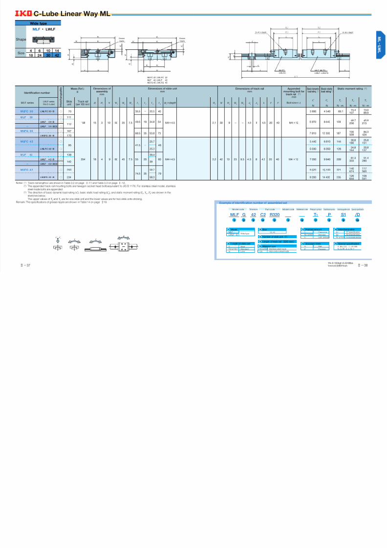
Ⅱ−37
C-Lube Linear Way ML
Ⅱ−38
1N=0.102kgf=0.2248lbs.1mm=0.03937inch
Identification number
I n t e r c h a n g e a b l e Mass (Ref.)
gDimensions of
assemblymm
Dimensions of slide unitmm
Dimensions of track railmm
Appendedmounting bolt for
track rail(2)
mm
Basic dynamicload rating(3)
Basic staticload rating(3)
Static moment rating(3)
MLF seriesLWLF series (No C-Lube)
Slideunit
Track rail(per 100 mm)
H H 1
N W 2
W 3
W 4
L1
L2
L3
L4
M 1×depth H
3W H
4W
5W
6d
3d
4h E F Bolt size×R
C
N
C 0
N
T 0
N・m
T X
N・m
T Y
N・m
M LFC 30 LWLFC 30…B ○ 70
198 15 3 10 50 35 7.5
35.5 − 20.5 40
M4×4.5 3.1 30 9 − − 4.5 8 4.5 20 40 M4×12
3 890 4 540 69.115.4
10713.089.9
MLF 30 ○ 111
49.5 18 34.8 54 5 970 8 440 12848.7
25640.8
215LWLF 3 0…B ○
112− LWLF 3 0…BCS ○
M LFG 30 ○ 16768.5 35 53.8 73 7 810 12 300 187
100508
84.3426LWLFG 30…B ○ 170
M LFC 42 ○
95
294 16 4 9 60 45 7.5
41.5 −
25.7
46
M4×4.5 3.2 42 10 23 9.5 4.5 8 4.5 20 40 M4×12
5 440 6 810 14430.8
18025.8
151
LWLFC 42…B ○ 25.3 5 030 6 050 12824.8
16420.8
137
MLF 42 ○ 138
55 20
39.4
60 7 050 9 840 20961.3
33351.4
280LWLF 4 2…B ○
140 39− LWLF 4 2…BCS ○
M LFG 42 ○ 200
74.5 35
58.7
79
9 520 15 100 321140674
117565
LWLFG 42…B ○ 204 58.3 9 200 14 400 305126644
106541
Notes(1) Track rail lengths L are shown in Table 3.2 on page Ⅱ-11 and Table 3.3 on page Ⅱ-12.(2) The appended track rail mounting bolts are hexagon socket head bolts equivalent to JIS B 1176. For stainless steel model, stainless
steel made bolts are appended.(3) The direction of basic dynamic load rating (C ), basic static load rating (C
0 ), and static moment rating (T
0, T
X, T
Y ) are shown in the
sketches below.
The upper values of T X
and T Y
are for one slide unit and t he lower values are for two slide units sticking.
Remark: The specifications of grease nipple are shown in Table 14 on page Ⅱ 18. Example of identification number of assembled set
Model code
MLF
Dimensions Part code
R320C242G
Preload symbol Classificationsymbol Special specification
T1 /DP
Interchangeable code
S1
Model code
1 12 87543 109
Material code
6
MLFModel
Wide typeLWLF…B
1
Number of slide unit(2)4
Size30, 42
3
Length of track rail(320 mm)5
S1
Interchangeable
S2 S2 specification
S1 specification
No symbol Non-interchangeable specification
9
T 0
Preload amount
No symbol Standard
Clearance
T 1 Light preload
7
P
Accuracy class
Precision
8
H High
Special specification
A, BS, D, E,1, LR, MNN, Q, RE, S, U, W, Y
10
No symbol
Length of slide unit
Standard
G Long
2
C ShortNo symbol
Material type
CS High carbon steel made
Stainless steel made
6
Wide type
Shape
Size4 14106
302418 42
MLF ・ LWLF
C C 0
T X
T 0
T Y
MLFC 42, LWLFC 42
MLF 42, LWLF 42
MLFG 42, LWLFG 42
W 2
W 3
W 5
W 6
W 2
W N
W 4
W 3
W N
W 4
H
H 1
H 3
H 3
H
H 1
L3
L3
L2
E E F
H 4
L(1)
( L1)
( L4)
( L1)
( L4)
d 4
d 3
h
2− M 1×depth 4− M 1×depth
MLFCLWLFC
MLF, MLFGLWLF, LWLFG
Grease
nipple
Grease
nipple