Embed Size (px)
Citation preview

IJTAG VS JTAG VS IEEE 1500 ECT | TECHNICAL
TUTORIAL – 2ND EDITION
BY AL CROUCH
Vice-Chairman of the IEEE 1687 IJTAG Working Group

IJTAG vs JTAG vs IEEE 1500 ECT | Technical Tutorial – Second Edition
2
Al Crouch Al investigates the use of embedded instruments for IC test and debug,
board test and debug, and software debug. He is a Senior Member of the
IEEE and serves as the vice chairman of the IEEE 1687 IJTAG working
group that is developing this standard for embedded instruments; and is the
chair for the IEEE 1687.1 study group to extend the access interfaces
associated with 1687. He has contributed significantly to the IEEE 1687 hardware architecture
definition. Al is also a member of the P1838 Working Group on 3D test and debug, and co-chair
of the iNEMI BIST group, which is defining the use of embedded instruments for board test.
Al’s work experience includes various design-for-test, debug and test-automation positions at
test tools companies, including ASSET InterTech, where he served as chief technologist,
semiconductor companies, such as TI, DEC and Motorola, as well as chief scientist at startup
companies DAFCA and INOVYS. Al has published extensively in journals, industry magazines,
and conference proceedings, and is an inventor on 20 issued patents.

IJTAG vs JTAG vs IEEE 1500 ECT | Technical Tutorial – Second Edition
3
Table of Contents Executive Summary ........................................................................................................................ 6
Introduction ..................................................................................................................................... 8
Differences among the three standards ....................................................................................... 9
Creeping Overlap ...................................................................................................................... 14
Understanding and Comparing Hardware Architectures .............................................................. 15
Comparing the IEEE 1149.1 and IEEE 1500 Hardware Architectures .................................... 18
Scalability Problems with IEEE 1149.1 and IEEE 1500 Instruction-Based Architectures ...... 22
The Daisy-Chained TDR Configuration ............................................................................... 23
The Single-Instruction Per Instrument Configuration .......................................................... 24
Comparing the IEEE 1149.1/1500 and IEEE 1687 Hardware Architectures ....................... 27
Key Differences supported by IEEE 1687 IJTAG Hardware Architecture .................................. 33
Separating Hardware Control from Instrument Interface ............................................................. 36
One Chip: One TAP Controller ................................................................................................ 37
Plug-and-Play Interface for Portability ..................................................................................... 40
Description Language and Operational Protocols for JTAG and IJTAG ..................................... 45
IEEE 1687 ICL/PDL versus IEEE 1149.1 BSDL/SVF versus IEEE 1500 CTL/STIL ............ 47
IEEE 1149.1 JTAG (Boundary Scan) ................................................................................... 47
IEEE 1500 Embedded Core Test .......................................................................................... 48
IEEE 1687 IJTAG (Embedded Instrumentation) .................................................................. 48
IEEE 1687 IJTAG’s PDL versus IEEE 1149.1-2013 JTAG’s PDL ......................................... 51
The Practical Usage of IEEE 1149.1, IEEE 1500, and IEEE 1687 .......................................... 54
Conclusions ................................................................................................................................... 56
Learn More.................................................................................................................................... 57
Appendix ....................................................................................................................................... 58

IJTAG vs JTAG vs IEEE 1500 ECT | Technical Tutorial – Second Edition
4
Introduction to IEEE 1149.1 ..................................................................................................... 58
Introduction to IEEE 1500 ........................................................................................................ 60
Introduction to IEEE 1687 Internal JTAG (IJTAG) ................................................................. 62
Table of Figures Figure 1: Capabilities of IEEE 1687 IJTAG, IEEE 1149.1 JTAG and IEEE 1500 ECT ............... 6
Figure 2: Hardware similarities and differences account for the overlap of standards ................ 15
Figure 3: The IEEE 1149.1 JTAG Finite State Machine (FSM) .................................................. 16
Figure 4: The IEEE 1149.1 TAP (left) with register architecture and protocol FSM .................. 19
Figure 5: The IEEE 1500 Wrapper Serial Port (right) and register architecture .......................... 19
Figure 6: Where IEEE 1500 fits within IEEE 1149.1 ................................................................... 21
Figure 7: Where daisy-chained IEEE 1500 fits within IEEE 1149.1 JTAG ................................. 22
Figure 8: Inefficient instrument access with long daisy-chained scan paths ................................ 24
Figure 9: Inefficiency in one-instrument-at-a-time/one-instruction architecture ......................... 26
Figure 10: The Segment Insertion Bit (SIB) adds a scan path ..................................................... 28
Figure 11: The Segment Swap Bit (SSB) selects a mutually-exclusive active scan segment ..... 28
Figure 12: An IJTAG architecture with three instruments and three SIBs .................................. 30
Figure 13: Hierarchical IJTAG architecture; SIBs and nested SIBs opening multiple scan paths....................................................................................................................................................... 31
Figure 14: IJTAG architecture with SIBs and NIBs configuring the scan path configuration .... 32
Figure 15: Where IEEE 1687 IJTAG fits within an IEEE 1149.1 JTAG architecture ................ 33
Figure 17: SIBs daisy-chained to TDI-TDO scan chain .............................................................. 35
Figure 18: Side-by-side comparison of IEEE 1149.1 JTAG and IEEE 1687 IJTAG routing ..... 36
Figure 19: IJTAG architecture with multiple eTAPs ................................................................... 38
Figure 20: Multiple eTAPs enabled by IEEE 1149.1 instructions............................................... 39
Figure 21: IJTAG architecture with multiple eTAPs and a configuration register ...................... 40
Figure 22: A portion of an IEEE 1687 network with IEEE 1687 interface ................................. 41
Figure 23: Embedded memory BIST instrument with targeted memory array ........................... 43
Figure 24: Embedded instrument with associated PDL vectors .................................................. 44
Figure 25: IP cores with IEEE 1500 wrappers controlled by JTAG TAP Controller.................. 61
Figure 26: An IJTAG architecture showing network, instrument interface and vectors ............. 64

IJTAG vs JTAG vs IEEE 1500 ECT | Technical Tutorial – Second Edition
5
Figure 27: Embedded instrument connections to TAP described in ICL .................................... 65
Figure 28: IJTAG architecture with SIBs and NIBs .................................................................... 66
Figure 29: The active portion of the JTAG FSM for IJTAG operations ..................................... 66
Table of Tables Table 1: Prominent capabilities of IEEE 1687, IEEE 1149.1-2013 and IEEE 1500 ................... 13
Table 2: A summary of IEEE 1687 Scan Path Elements ............................................................. 32
Table 3: Standard Languages ....................................................................................................... 45
Table 4: Comparison of IEEE 1687 vs IEEE 1149.1-2013 PDL Commands ............................. 52
© 2016 ASSET InterTech, Inc.
ASSET and ScanWorks are registered trademarks, and SourcePoint and the ScanWorks logo are trademarks of ASSET
InterTech, Inc. All other trade and service marks are the properties of their respective owners.

IJTAG vs JTAG vs IEEE 1500 ECT | Technical Tutorial – Second Edition
6
Executive Summary
Engineers working with embedded instrumentation – which is defined as intellectual property
(IP) embedded within chips to support test and measurement applications – may find themselves
using the capabilities of several IEEE standards, including IEEE 1687-2014 Internal JTAG
(IJTAG), IEEE 1149.1 Boundary Scan (often simply referred to as JTAG) and the IEEE 1500-
2005 Embedded Core Test (ECT) standard. Contrary to any confusion in the industry, each of
these three standards was developed for distinct and specific purposes. In fact, each standard has
capabilities that the others do not, even though some of their capabilities may be similar. (Figure
1)
Figure 1: Capabilities of IEEE 1687 IJTAG, IEEE 1149.1 JTAG and IEEE 1500 ECT
Moreover, standards change over time. Since its first ratification in 1990, the oldest of these
three standards, IEEE 1149.1 JTAG, has evolved to include features that are far removed from its
original purpose of non-intrusive (probe-less) structural circuit board test. Since the 1990s,
embedded instrumentation has exploded, bringing with it many requirements that were totally

IJTAG vs JTAG vs IEEE 1500 ECT | Technical Tutorial – Second Edition
7
unforeseen when the original IEEE 1149.1 JTAG standard was developed. Several standards,
including IEEE 1687 IJTAG, IEEE 1500 ECT and several others have used the JTAG standard’s
Test Access Port (TAP) and controller because these have been widely deployed in chips and
they provide non-intrusive physical access to the internal operations of semiconductors.
Generally speaking, IEEE 1687 IJTAG is able to manage, coordinate and schedule embedded
instruments while IEEE 1500 is able to access and manipulate complex embedded cores through
the access provided by IEEE 1149.1 JTAG’s TAP and controller.
Recent changes in the IEEE 1149.1 JTAG standard (IEEE 1149.1-2013) seem to suggest that it is
evolving away from its original purpose in circuit board test and migrating toward other
applications, such as chip test. This may or may not be a good thing for circuit board test. One
can question whether the original intent of a standard such as IEEE 1149.1 JTAG is being
compromised when it evolves into areas that have very different requirements from those that led
to its development in the first place.
This eBook compares and contrasts the capabilities of these three standards to illustrate how the
unique capabilities of each can be applied to achieve engineering goals in development,
manufacturing and field support. In particular, some of the confusion that has arisen around the
IJTAG and JTAG standards will be dispelled by explaining how the seminal objectives upon
which these standards were developed actually limit their growth and applicability to new use
cases and that these new use cases are beyond the scope of the standards’ original objectives as
well as applications. In addition, the strengths of each standard will also be described. In fact,
understanding where each standard should not be used is as important as understanding where
they should be applied. In addition, it should be noted that any one chip or circuit board may
require the capabilities of all three standards because each one has certain capabilities not found
in the others. In addition, the adoption of any one standard may be driven by the IP provider
since the standards supported by any IP may be limited. Moreover, the ease of integrating IP may
require the support for all three standards at the IC level.
IJTAG vs JTAG vs IEEE 1500 ECT | Technical Tutorial – Second Edition
8
Introduction
A cursory understanding of the objectives that drove the original development of the IEEE
1149.1 JTAG, IEEE 1500 ECT and IEEE 1687 IJTAG standards will indicate the use cases,
strengths and weaknesses of each.
When the development of the IEEE 1149.1 Boundary-Scan Standard (JTAG) began in the late
1980s followed by its first IEEE ratification in 1990 (IEEE 1149.1-1990), its goal was to provide
a more effective circuit board test methodology that would verify the connectivity of chips to
boards. At the time, new chip packaging technologies, such as surface mount ball grid arrays
(BGA), were making the pins on chips inaccessible to probe-based validation, test and debug
methods because the pins were hidden under the silicon die. Test and measurement equipment
such as oscilloscopes, in-circuit testers (ICT) and others have traditionally relied on probe-based
access to chips and circuit boards. In essence, surface mount chips began to erode the
economical probe access that the industry previously had available. In reaction to this situation,
chips conforming to the IEEE 1149.1 JTAG standard added limited logic to support the
boundary-scan test methodology, which eliminated the need for probe access. The IEEE 1149.1
standard has been updated several times since it was first ratified. The last such update in 2013
(IEEE 1149.1-2013) introduced several features that overlap certain functionalities included
within the IEEE 1687 and IEEE 1500 standards. For additional background information on the
IEEE 1149.1 Boundary-Scan Standard, see the Appendix.
The IEEE 1500 Embedded Core Test (ECT) standard was
ratified in 2005. Prior to IEEE 1500’s ratification, multiple IP
cores were being integrated on-chip, but these cores typically
numbered in the tens of cores. These cores could be hard cores
(physical layout macros) or soft cores (synthesizable HDL or
RTL). IEEE 1500 ECT provided a methodology for validating
that the cores embedded in a chip could interact as specified by
including self-contained tests and by supporting a core
boundary wrapper. Today, IP cores in a typical system-on-a-
Examples of Embedded Instruments: • Memory BIST • Scan • Scan Compression • Logic BIST • PLL BIST • Debug trace • Capture triggers • Assertions • Voltage monitors • Temperature monitors • Frequency monitors • Power mode settings • Bus configurations

IJTAG vs JTAG vs IEEE 1500 ECT | Technical Tutorial – Second Edition
9
chip (SoC) may number well over 100. For additional background information on the IEEE 1500
Embedded Core Test Standard, see the Appendix.
Development of the IEEE 1687 Embedded Instrumentation (IJTAG) Standard began in 2005
when the number and types of embedded instruments inside chips began to proliferate
dramatically. Chip designers had discovered that embedded instrumentation was one of the most
cost-effective and efficient means of testing, validating, characterizing and debugging their ICs.
(It was more cost-effective to use features on-silicon instead of using external equipment such as
a multi-million-dollar ATE system.) Additionally, the capabilities of the embedded instruments
within chips were being applied to additional applications, including the debug, validation and
test of circuit boards. An example of these wider applications would be applying a SerDes built-
in-self-test (BIST) instrument to verify the high-speed low-voltage differential signaling (LVDS)
traces on a circuit board.
There was little or no consistency among embedded instruments with regards to management
and coordination procedures, access ports and usage protocols, on-chip access architectures and
other aspects of their operations. For instance, certain types of instruments were used in different
environments and, therefore, supported different access mechanisms. Wafer probe, for example,
accessed embedded process monitors (ring oscillators) through probe pads; chip test accessed
manufacturing scan and scan compression through a custom pin interface; and debug/yield-
analysis accessed debug and trace logic through the JTAG port. IEEE 1687 IJTAG was
developed to ensure the inherent portability of embedded instruments and to make the
application of embedded instruments more effective and efficient without disturbing the
purposes of other standards, such as IEEE 1149.1 JTAG. For additional background information
on the IEEE 1687 Embedded Instrumentation Standard, see the Appendix.
Differences among the three standards
On the surface, these three standards may seem somewhat similar, but in reality there are
significant differences among them. Since IEEE 1149.1 JTAG is the oldest and most established
of these standards (IEEE 1149.1-1990), it established the definition of the register configurations
and the state machine-based protocol that were adopted as a foundation for the other two

IJTAG vs JTAG vs IEEE 1500 ECT | Technical Tutorial – Second Edition
10
standards. As a result, one could easily believe that all three standards have similar hardware
architecture. However, since the use cases for each standard are quite different, the nature of
their hardware architectures is also different. The biggest differences, however, are in their
methods of documentation; that is, their architectures and vector descriptions. Therefore, the
differences among the three standard can be found in both the hardware architectures and their
description languages.
As mentioned previously, since its first ratification in 1990, IEEE 1149.1 JTAG has been
deployed in circuit board test and validation applications, and its on-chip Test Access Port (TAP)
and TAP Controller have become de facto methods for accessing embedded on-chip resources.
IEEE 1149.1 JTAG’s original use case was to provide on-chip logic to support board
interconnect testing. The JTAG TAP, which is defined as four mandatory (TCK, TMS, TDI,
TDO) and one optional (TRST*) package pins for accessing JTAG’s internal functionality, is
simply referred to as the JTAG port and IEEE 1149.1’s mandatory and optional data registers are
the vehicles for accessing or implementing the standard’s functionality.
JTAG’s board test purposes are executed through a centralized instruction register that is
operated by a dedicated portion of the JTAG state machine. This results in the separation of
instruction selection from data operations. The original intent of the IEEE 1149.1 JTAG standard
was to define and describe registers that had operational purposes narrowly defined by the
standard so that the selection of an instruction mapped onto a known test operation. Here are a
few examples: 1) updating an EXTEST instruction (encoding) into the JTAG Instruction
Register (IR) results in the Boundary Scan Register (BSR) taking on a particular configuration to
statically set the output logic values of the output pins of the chip; 2) the use of the IDCODE
instruction results in the access and reading of a 32-bit register that contains a defined value
established by the chip provider, the chip family and a JEDEC standard; and 3) the use of the
BYPASS instruction resolves the entire chip’s contribution to the board’s overall scan path to a
single bit.
The IEEE 1500 ECT standard has a similar use case and functionality to IEEE 1149.1 JTAG but
IEEE 1500 ECT specifies a means for wrapping embedded cores so they can contain test modes
for validating the core’s operations and for conducting an interconnect test when the core is

IJTAG vs JTAG vs IEEE 1500 ECT | Technical Tutorial – Second Edition
11
embedded on a particular chip. An IEEE 1500 core wrapper is similar to an IEEE 1149.1 JTAG
register architecture, but the IEEE 1500 standard does not specify that a state machine must be
part of the architecture. The IEEE 1500 architecture is meant to be operated and synchronized at
the test controller level of the SoC by the IEEE 1149.1 TAP Controller state machine. An IEEE
1500 core might house multiple test and debug functions that parrot how IEEE 1149.1 provides
test functions for a chip, but these functions are applied to the embedded core. In this respect,
one could think of an IEEE 1500 wrapper as IEEE 1149.1 JTAG and boundary scan for a core.
In this sense, the core might represent a “virtual chip.” (That is, a core is a design unit without
the chip package pins. In other words, a core is to a SoC as a chip is to a circuit board.) The test
functions or instruments housed inside an IEEE 1500 core wrapper are accessed by an IEEE
1500 Core Data Register (CDR) or Wrapper Data Register (WDR), which are equivalent to an
IEEE 1149.1 TDR. The IEEE 1500 Wrapper Architecture allows a wrapped core to be delivered
with tests already included, thereby adding a measure of portability to core test. It must be noted
that a core provider has the option of delivering the core with an IEEE 1500 wrapper and
predefined tests or just the core itself. If only a core is delivered, the chip integrator will have to
wrap the core and add tests that meet the needs and purposes of the specific SoC.
IEEE 1687 IJTAG’s use case has always been to provide access to embedded instruments so
they could be operated for test, debug, environmental monitoring, process monitoring, and
functional configuration, thereby bringing multiple use environments under one standard access
mechanism. The stated purpose of the IJTAG standard is to “facilitate vector retargeting” from
embedded instruments to the chip or board level. Retargeting is accomplished by providing
instrument vectors written at the instrument interface and by providing a minimal description of
the access architecture that delivers the vectors, thereby making embedded instruments portable
and independent of the access architecture.
Since IEEE 1687 IJTAG was the last of these three standards to be developed, one can better
understand what its strengths and use cases are by examining those of the other two, IEEE
1149.1 JTAG and IEEE 1500 ECT. Although IEEE 1687 IJTAG was developed so that it would
not overtly duplicate the capabilities of IEEE 1149.1 JTAG and IEEE 1500 ECT, the IEEE 1687

IJTAG vs JTAG vs IEEE 1500 ECT | Technical Tutorial – Second Edition
12
IJTAG working group had no control over the working groups overseeing the further
development of these other two standards.
The IEEE 1687 IJAG working group started with the belief that there were shortcomings with
both IEEE 1149.1 JTAG and IEEE 1500 ECT. For example, IEEE 1149.1 JTAG’s centralized
instruction register architecture was seen as a physical hindrance to scalability as the number of
embedded instruments grew. In addition, the fixed and somewhat rigid aspects of the JTAG
architecture, such as selected instructions accessing only a fixed-length TDR, limited an
engineer’s ability to design access networks with engineering tradeoffs in mind, like power, area,
routing, non-centralized decode and others. In addition, the operational tradeoffs engineers could
incorporate, such as flexible instrument scheduling, instrument concurrence of operation and
scan path length management, were also limited under the JTAG standard. The IEEE 1687
IJTAG working group believed JTAG or ECT involved too much overhead for individual simple
instruments. (Compliance to the IEEE 1149.1 JTAG standard requires support of the boundary
register, bypass register, IDCode register, instruction register and some mandatory instructions.)
Also, the JTAG standard could not efficiently handle concurrent and flexible instrument
scheduling. The IEEE 1687 IJTAG working group concluded that something simpler than IEEE
1149.1 JTAG and IEEE 1500 ECT was needed.
Some of the other objectives of the IEEE 1687 IJTAG working group were to avoid affecting the
IEEE 1149.1 JTAG and IEEE 1500 ECT standards to the extent that their use cases would be
compromised or that using them would be made more difficult. This meant that the board test
community, which expected to use the defined IEEE 1149.1 JTAG instructions of EXTEST,
BYPASS, IDCODE, and a handful of other defined instructions, should not be burdened with the
hundreds or thousands of instructions that might be associated with IC test and their
documentation within JTAG’s Boundary-Scan Description Language (BSDL) file. The IEEE
1687 IJTAG working group concluded that the content accessed for IC test should somehow be
accessed by just a few instructions and that the documentation of these instructions should not
bloat a chip’s BSDL file. (Similar considerations were made for the IEEE 1500 Wrapper-IR
(WIR) and CTL files.) This led to the development of a different description language for the
IEEE 1687 IJTAG architecture. In addition, the purpose of IEEE 1687 IJTAG was to allow

IJTAG vs JTAG vs IEEE 1500 ECT | Technical Tutorial – Second Edition
13
portable instruments to be delivered with their vectors and for those vectors to be reused or
retargeted with automation tools instead of manually modifying vectors followed by chip-level
re-simulation. So, a vector language with an application focus different from IEEE 1149.1
JTAG’s, which is restricted to its TAP and access network, was needed. This language would be
focused on the internal embedded instrument, not the IC or an SoC’s TAP package pins.
In short, the three standards, IEEE 1149.1 JTAG, IEEE 1500 ECT and IEEE 1687 IJTAG may
all be based on the same basic operations (Reset - Shift – Capture – Update), but their particular
use cases result in significant applied differences as well as different sets of pros and cons for
each standard.
Table 1: Prominent capabilities of IEEE 1687, IEEE 1149.1-2013 and IEEE 1500
Feature IEEE 1687 IJTAG
IEEE 1149.1-2013 JTAG
IEEE 1500 ECT
Includes Hardware FSM Controller No Yes No Includes an Instruction Register No Yes Yes Includes Mandated Defined Instructions No Yes Yes Supports Persistent Instructions No3 Yes No Separation of Instruction and Data No Yes Yes Includes Defined Connection to Controller Yes Yes No Data-based operations only Yes No No1 Mandates a Boundary Register No Yes Yes Mandates a Bypass Register No Yes Yes Mandates an ID Register No Yes Yes Support of a Test Data Register (TDR) Yes Yes Yes Support of Network Instruction Bits Yes No No Support of Network Configuration Bits Yes Yes No Portable instruments supported Yes Yes2 No Embedded TAP Controller supported Yes No No Architecture description language ICL BSDL CTL Test Data Register based vectors No Yes Yes Portable instrument vectors supported Yes No No Vector description language PDL SVF, PDL STIL
1. An IEEE 1500 Wrapper may be operated from only the DR-side of the IEEE 1149.1 state machine, but the wrapper itself still
separates instruction operations from data operations.
2. IEEE 1149.1 JTAG supports instruments if they are designed and delivered with a Test Data Register attached and the vectors are
written to the TDR. IEEE 1687 IJTAG allows and supports true portable instruments and vectors with no required TDR.
3. IEEE 1687 IJTAG has embedded instruction bits in the data scan path that are used mainly to configure the scan path, conduct local
resets, and apply action limitations such as “deny capture.” These instructions are written on each DR-Scan and are not persistent
through reset.

IJTAG vs JTAG vs IEEE 1500 ECT | Technical Tutorial – Second Edition
14
Table 1 above summarizes some of the more prominent capabilities of the three standards. It
shows that both IEEE 1500 ECT and IEEE 1687 IJTAG are controller-less standards, which rely
on IEEE 1149.1 JTAG and its TAP Controller to provide operational signals and sequences. Of
the three standards, only IEEE 1149.1 JTAG specifies a controller. Both IEEE 1149.1 JTAG and
IEEE 1500 ECT mandate a register architecture that includes boundary registers, ID registers,
bypass registers and a formal instruction register. In contrast, IEEE 1687 IJTAG only mandates
TDR registers and optionally allows embedded instruction and configuration bits in the data-side
scan path. IEEE 1149.1 JTAG and IEEE 1500 ECT both define instructions such as BYPASS
and IDCODE since each of these standards set aside a fixed portion of their architectures to
support these instruction-based features. Only the most recent revision of the JTAG standard,
IEEE 1149.1-2013, supports reset-independent persistent instructions. IEEE 1687 IJTAG is the
only standard to support multiple embedded TAPs and TAP Controllers. IEEE 1149.1-2013
JTAG and IEEE 1687 IJTAG support variable-length scan paths by allowing the inclusion of
Segment-Select or Segment-Insertion Bits. And each of the three standards mandates different
description languages.
Creeping Overlap
The confusion over the respective functionality of IEEE 1149.1 JTAG and IEEE 1687 IJTAG
began in 2011 when the IEEE 1149.1 JTAG working group opened an IEEE Project
Authorization Request (PAR) to update the IEEE 1149.1 JTAG standard. The IEEE 1687 IJTAG
working group had begun developing its standard in 2005. IEEE 1149.1-2013 JTAG was ratified
in 2013, while IEEE 1687 IJTAG passed ballot in 2014. Some companies and individuals
participated on both committees.
IEEE 1149.1-2013 JTAG added several new features to the standard but it steadfastly maintained
a dual register separation architecture which separated data and instruction operations and was
made up of centralized instructions and multiple parallel data registers. Although some of the
new features of IEEE 1149.1 JTAG by definition overlap the features of both IEEE 1687 IJTAG
and IEEE 1500 ECT on a purely functional level, in real-world implementations some of these
same capabilities could be accomplished more effectively and efficiently with either IEEE 1687

IJTAG vs JTAG vs IEEE 1500 ECT | Technical Tutorial – Second Edition
15
IJTAG or IEEE 1500 ECT. In addition, both IEEE 1687 IJTAG and IEEE 1500 ECT include
capabilities not found in IEEE 1149.1-2013 JTAG at all.
Understanding and Comparing Hardware Architectures
Figure 2: Hardware similarities and differences account for the overlap of standards
The hardware architectures specified by IEEE 1149.1 JTAG, IEEE 1500 ECT and IEEE 1687
IJTAG (Figure 2) have a major effect on the scalability, portability and use cases for each
standard.
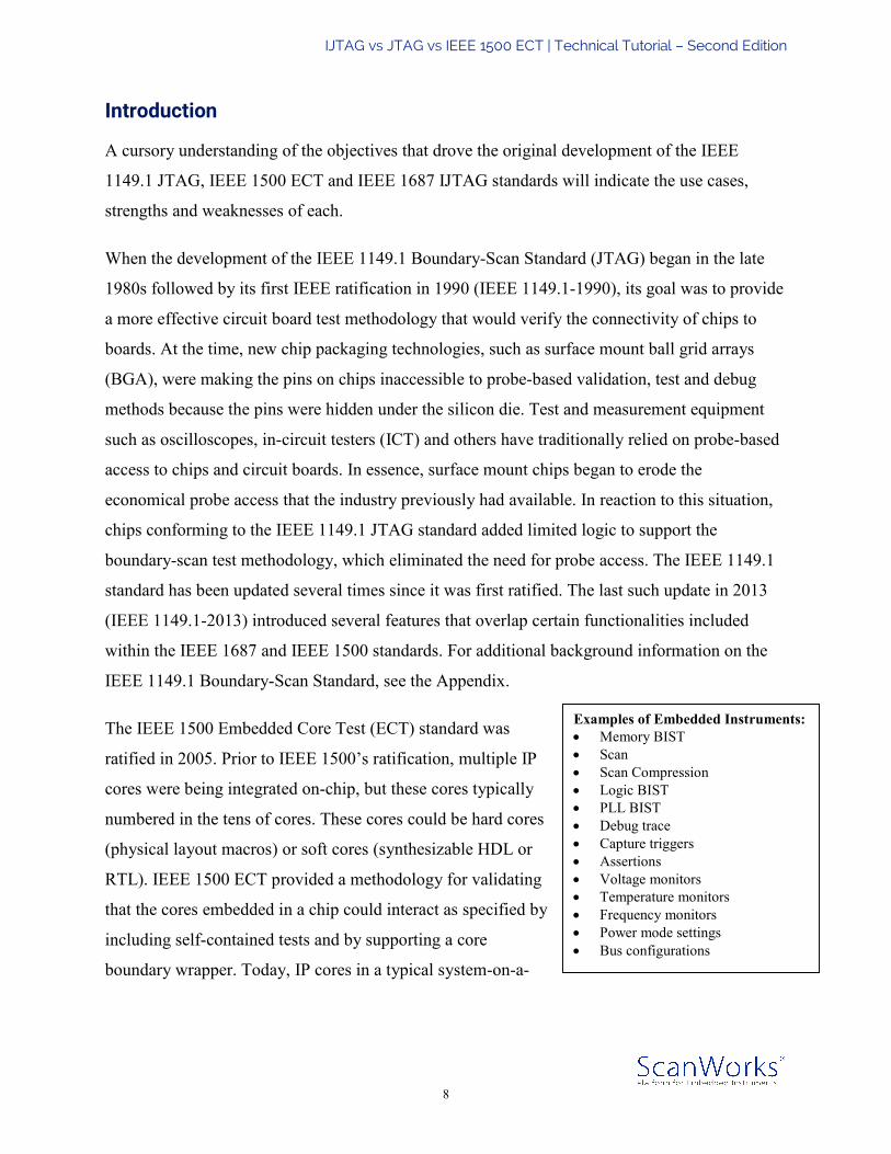
As mentioned previously, IEEE 1149.1 JTAG defines a controller. This controller consists of a
four-bit finite state machine (FSM), which generates 16 states that control the operating
sequences defined in the standard. The inputs to the IEEE 1149.1 JTAG FSM (Figure 3) are two
of the four signals defined in the standard, the Test Mode Select (TMS) and Test Clock (TCK).
The states in the FSM that are used to generate the key operational signals are: Test-Logic-Reset
(TLR), which may generate the Reset Signal; Shift-IR/DR, which may generate the Shift-Enable
signals; Capture-IR/DR, which may generate the Capture-Enable signals; and Update-IR/DR,
IJTAG vs JTAG vs IEEE 1500 ECT | Technical Tutorial – Second Edition
16
which may generate the Update-Enable signals. The definition of the controller and its operations
is unique to the IEEE 1149.1 JTAG standard. For the IEEE 1687 IJTAG standard, only the data-
side operations of the controller are important. IEEE 1500 ECT may be connected to the IEEE
1149.1 JTAG TAP Controller in such a way that it may be operated with only data-side
operations or it may require both data-side and instruction-side operations.
Figure 3: The IEEE 1149.1 JTAG Finite State Machine (FSM)
No physical controller is specified in the IEEE 1687 IJTAG or IEEE 1500 ECT standards. IEEE
1500 and IEEE 1687 have been designed with a separable (plug-and-play) signal interface that
makes use of the signals generated and the protocol established by the IEEE 1149.1 JTAG
controller. IEEE 1500 ECT may connect to an IEEE 1149.1 JTAG FSM on both the data-side
and instruction-side because both IEEE 1149.1 and IEEE 1500 have formal instruction registers.
Alternatively, IEEE 1500 may connect to only the data-side operations of the state machine. In
contrast, IEEE 1687 IJTAG only makes use of the data-side of the JTAG FSM since IEEE 1687
IJTAG supports no formalized instruction register, but does allow data-side embedded
instruction or embedded configuration bits.

IJTAG vs JTAG vs IEEE 1500 ECT | Technical Tutorial – Second Edition
17
One of the development goals of IEEE 1687 IJTAG was to maintain flexibility and re-
configurability. As a result, IEEE 1687 could utilize other controllers in the future if warranted
by industry demand. This could be accomplished by connecting the IEEE 1687 separable
interface to a different controller that would generate the Shift-Enable, Capture-Enable, Update-
Enable, and Reset signals. At the time of this writing, the IEEE 1687 IJTAG standard specifies
and includes only the IEEE 1149.1 JTAG Controller as the preferred implementation, but the
standard also provides a generic description of an AccessLink, which shows how alternative
controllers could be associated with an IEEE 1687 IJTAG serial network. A formal IEEE
P1687.1 effort will update and define alternate controller access for 1687 networks in the future.
To a certain extent, the hardware architectures defined by IEEE 1149.1 JTAG and IEEE 1500
ECT share many characteristics. In general, the IEEE 1149.1/1500 architecture is comprised of a
collection of fixed-length registers that are included in an active scan path through the placement
of an instruction in an associated instruction register. This differs decidedly from the flexible
hardware architecture of an IEEE 1687 IJTAG on-chip network of embedded instruments. A
single IEEE 1687 AccessLink instruction selects the network. Then, single-bit in-line embedded
instructions configure the network. In a sense, these single-bit instructions act as switches or
traffic lights to direct traffic over the various segments of the on-chip network of embedded
instruments. One of the changes in IEEE 1149.1-2013 JTAG is the addition of “segment-select
bits,” which incorporate some of this functionality into the IEEE 1149.1 JTAG standard. IEEE
1687 IJTAG, unlike the IEEE 1149.1/1500 hardware architectures, makes no distinction between
data and instructions in its network.
IEEE 1500 ECT also has its own unique capabilities that are not supported in IEEE 1149.1
JTAG or IEEE 1687 IJTAG. These include the Wrapper Parallel Port (WPP) and the Transfer
operation. These are defined hardware configurations that are optimized for core-based test and
the reuse of functional interface or boundary registers in the boundary wrapper.
Another unique characteristic of IEEE 1687 IJTAG is the inclusion of embedded Network
Instruction Bits (NIBs). In general, NIBs are in-line data bits in the scan path that can modify
other portions of the scan path, which comprises the IEEE 1687 IJTAG on-chip network of
embedded instruments. These bits may be used to gate the Capture-Enable, Update-Enable and
IJTAG vs JTAG vs IEEE 1500 ECT | Technical Tutorial – Second Edition
18
Reset signals to provide a Deny-Capture, Deny-Update, and Deny-Reset functionality. In
addition, these bits may enable a capability known as Local-Reset, which resets a TDR or scan
path segment and which is initiated by a NIB in the scan path. These capabilities are very useful
during scan chain debug when, for example, a hold-time violation through a scan path flip-flop
must be debugged or diagnosed.
Perhaps one of the most significant capabilities of IEEE 1687 IJTAG that is not supported by
IEEE 1149.1 JTAG or IEEE 1500 ECT is multiple embedded TAP Controllers. This became a
problem when IEEE 1500 ECT adoption began in the industry. Some IP providers would deliver
a core with an IEEE 1500 wrapper that also included the IEEE 1149.1 TAP state machine.
Instead of the 1500 plug-and-play interface defined in the standard, the delivered IP would
instead support an IEEE 1149.1 TAP signal interface. In effect, such a core would include a
complete IEEE 1149.1 architecture that would function as a secondary JTAG architecture to the
primary JTAG architecture of an IC or SoC. The question of how to incorporate multiple cores
each with its own TAP and TAP Controller into one SoC is not dealt with in a cost-effective
manner in the IEEE 1149.1 JTAG or IEEE 1500 ECT standards. So, IEEE 1687 IJTAG took on
the task of defining how multiple embedded JTAG TAPs could be incorporated within an IEEE
1687 IJTAG network and how these multiple TAPs would be described. However, an embedded
TAP should more properly be viewed as either an instrument or a scan path reconfiguration
element within the IJTAG network.
It must be noted that all three standards support fixed-length TDRs, but each standard has a
different method of documenting these registers.
Comparing the IEEE 1149.1 and IEEE 1500 Hardware Architectures
The two following graphics (Figure 4 and Figure 5) point out the similarities between the IEEE
1149.1 JTAG and IEEE 1500 ECT hardware architectures.
Figure 4 shows the IEEE 1149.1 JTAG architecture with its parallel set of Data Registers,
Instruction Register (1149.1-IR), the FSM and the instruction decode for generating Register
Control Signals. Several of the registers are required (mandated) functions, including the bypass
register (BYP), the ID code register (IDCode) and the Boundary Scan Register (BSR). (Note that

IJTAG vs JTAG vs IEEE 1500 ECT | Technical Tutorial – Second Edition
19
the BSR can only be constructed from cells defined in the IEEE 1149.1 and 1149.6 JTAG
standards.) One or more generic Test Data Registers (TDR) are optional for accessing embedded
instruments.
Figure 4: The IEEE 1149.1 TAP (left) with register architecture and protocol FSM
When the FSM is on the data-side (Figure 3), the active instruction in the Instruction Register
selects which register is active and, as a result, it is included in the active scan path. However,
when the FSM is on the instruction-side (Figure 3), only the Instruction Register is included in
the active scan path. This architecture is documented with the IEEE 1149.1 standard’s BSDL.
Figure 5: The IEEE 1500 Wrapper Serial Port (right) and register architecture
The IEEE 1500 ECT architecture shown in Figure 5 is extremely similar to the IEEE 1149.1
JTAG architecture in Figure 4. The register structure is practically identical except the registers
are renamed as wrappers. The IEEE 1500 Wrapper Bypass Register (WBY) performs the

IJTAG vs JTAG vs IEEE 1500 ECT | Technical Tutorial – Second Edition
20
function of IEEE 1149.1’s BYP; IEEE 1500’s Wrapper ID Code (WID) register corresponds to
IEEE 1149.1’s IDCode; and IEEE 1500’s Wrapper Boundary-Scan Register (WBR) mirrors
IEEE 1149.1’s BSR; and IEEE 1500’s Wrapper Instruction Register (WIR) represents the same
function as IEEE 1149.1’s IR. In IEEE 1500, one or more generic Core Data Registers (CDR) or
Wrapper Data Registers (WDR) are optional for accessing embedded instruments in a manner
similar to the IEEE 1149.1 TDR.
The main difference between the IEEE 1149.1 JTAG and IEEE 1500 ECT architectures is not
that the registers have been renamed, but that the IEEE 1149.1 FSM is not included as part of the
IEEE 1500 architecture. As a result, the IEEE 1149.1 TMS signal that operates the FSM is
replaced in IEEE 1500 by the control signals that are normally produced by the IEEE 1149.1
FSM: ShiftWR, CaptureWR, UpdateWR, and ResetN (where the WR represents the word
Wrapper on signals normally named ShiftDR or ShiftEn, for example). These signals must be
included as inputs to the wrapper architecture instead of the IEEE 1149.1 TAP TMS signal. The
IEEE 1149.1 TDI, TDO and TCK signals are included and are represented in IEEE 1500 as WSI,
WSO and WRCK, respectively. In addition, a separate IEEE 1500 signal, SelectWIR, selects the
Wrapper Instruction Register (WIR) to make the wrapped core part of an active scan path when
instructions need to be installed or changed. The SelectWIR signal may be generated when the
IEEE 1149.1 FSM is on the instruction-side (as the Select-IR signal is created for IEEE 1149.1)
or this signal may be generated on the data-side when a SelectWIR type of instruction is installed
in the IEEE 1149.1 IR. Where SelectWIR is generated depends on how the IEEE 1500 wrapper
unit is connected to the 1149.1 TAP controller. The entire IEEE 1500 architecture is documented
in that standard’s Core Test Language (CTL), which is its own standard, IEEE 1450.6.
The IEEE 1500 ECT standard does not specify a connection to the IEEE 1149.1 JTAG TAP.
Some implementations can connect one or more IEEE 1500 wrappers to the IEEE 1149.1 TAP
with a single instruction. The WIR is operated in concatenation to the IR when the FSM is on the
instruction-side and the IEEE 1500 Instruction is installed. (Essentially, this means that the IR
can change length depending on the active instruction.) More often though, the favored
implementation requires two instructions per IEEE 1500 wrapper unit: one IEEE 1149.1
instruction selects the IEEE 1500 wrapper WIR as the active scan path and the second IEEE

IJTAG vs JTAG vs IEEE 1500 ECT | Technical Tutorial – Second Edition
21
1149.1 instruction selects the IEEE 1500 Data Registers as the active scan path. The specific
active IEEE 1500 Data Register depends on the IEEE 1500 instruction contained within the
WIR. In this case, all IEEE 1500 operations are on the DR-Side of the IEEE 1149.1 FSM. This
type of connection is shown in Figure 6 where a complete IEEE 1500 Wrapper is subsumed
within the TDR-space of an IEEE 1149.1 JTAG architecture. Note that multiple IEEE 1500
wrappers may be selected by individual instructions or the wrappers may be daisy-chained
(Figure 7) and treated similarly to a board test architecture. (Those wrappers not active may be
placed in bypass to reduce the length added to the daisy-chain scan path to one bit for that
particular bypassed IEEE 1500 wrapper.)
Figure 6: Where IEEE 1500 fits within IEEE 1149.1

IJTAG vs JTAG vs IEEE 1500 ECT | Technical Tutorial – Second Edition
22
Figure 7: Where daisy-chained IEEE 1500 fits within IEEE 1149.1 JTAG
In summary, the intent of the IEEE 1149.1 JTAG and IEEE 1500 ECT hardware architectures is
to provide well defined test operations while maintaining a separation between the instructions
that configure the architecture as well as activate the test operations and the data that can be used
for test and debug purposes.
It should be noted that IEEE 1500 wrapper units sometimes cause malfunctions in 1149.1
JTAG/boundary-scan board test tools because the IEEE 1500 WIR instructions are invisible to
JTAG’s BSDL description of the 1149.1 architecture.
Scalability Problems with IEEE 1149.1 and IEEE 1500 Instruction-Based Architectures
The differences in hardware architectures between IEEE 1149.1/1500 and IEEE 1687 IJTAG are
critical with regards to issues of scalability. Over the upcoming decades as more and more
instruments are embedded on-chip or in multiple levels on complex multi-die packages, it will be
essential that the network connecting them must be extremely scalable and flexible so that it will
allow for engineering and operational tradeoffs, and take into consideration clock and power
domains as well as security instruments. The hardware architecture defined in the IEEE 1687

IJTAG vs JTAG vs IEEE 1500 ECT | Technical Tutorial – Second Edition
23
IJAG standard enables a scalable on-chip environment while the IEEE 1149.1/1500 architecture
is limited in scalability because the IEEE 1149.1/1500 architecture is based on centralized
instructions.
While the IEEE 1149.1 JTAG FSM that drives the IEEE 1149.1/1500 hardware architecture has
a dual instruction/data structure, the IEEE 1149.1/1500 hardware architecture itself is
instruction-based insofar as instructions configure the scan path and activate the operations of
any associated embedded instruments. This exclusive instruction orientation of the IEEE
1149.1/1500 architecture has inherent failings involving efficiency of operations and
management of resources.
The Daisy-Chained TDR Configuration
When instructions select or activate the scan paths for embedded instruments, one
implementation can result in a lengthy single TDR architecture. Referred to as a daisy-chain
configuration, the embedded instrument TDRs on the long active scan path will be daisy-chained
together (Figure 8). When a long scan path such as this is selected, everything on the scan path,
including all of the embedded instruments are active and consuming power. And, because of the
length of the scan path, access times for any given embedded instrument interface will be
relatively long.
Consider this example: 10 embedded instruments each with a 32-
bit interface comprise the scan path. To access all 10 instruments,
the single daisy-chained scan path would be 320 bits long. An
access to any single embedded instrument would require the
entire 320 bits to be shifted into the register chain and
subsequently updated. In addition, all 320 scan flip-flops would
be turned on, active and using power even though only one 32-bit
instrument interface was being accessed.
This architecture also features high risk. If only one bit is broken (stuck-at, open, hold-time
problems, slow clock, slow data etc.), the entire scan path will not shift correctly, possibly
disabling all of the embedded instruments on the chain. And lastly, there is no way to document
Deficiencies of daisy-chained scan path in the IEEE 1149.1/1500 architecture: • Long instruction lengths • Excessive power
consumption • High risk of failure • Absence of instrument
documentation

IJTAG vs JTAG vs IEEE 1500 ECT | Technical Tutorial – Second Edition
24
in IEEE 1149.1 JTAG’s BSDL all of the separate instruments on the path because features
connected to the access TDR are not officially part of the BSDL description. Generally, an
embedded instrument scan path is listed as private in IEEE 1149.1 and only the length of the
selected TDR is required to be documented in the BSDL.
Figure 8: Inefficient instrument access with long daisy-chained scan paths
This daisy-chained type of architecture is also not scalable because adding more embedded
instruments just makes matters worse. A scan path of 100 32-bit instruments results in a scan
path 3,200 bits long and 1,000 instruments resolves to a scan path 32,000 bits long. And, of
course, more power is consumed, access times get longer and the risk increases since a longer
scan path will include a greater number of possible points of potential failure.
The Single-Instruction Per Instrument Configuration
Another IEEE 1149.1 JTAG architecture would be to include a TDR for each embedded
instrument (Figure 9). In this structure, each instrument could be selected by its own unique
instruction. This type of configuration is sometimes referred to as a one-at-a-time access
architecture.

IJTAG vs JTAG vs IEEE 1500 ECT | Technical Tutorial – Second Edition
25
This configuration mitigates the risk of failure somewhat since a broken data scan chain only
disables access to one instrument. The power problem is
mitigated because instruments could be selected and activated
individually through each instrument’s TDR while other non-
active instructions may have quiescent TDRs by not receiving
clocks or active control signals. Unfortunately, this
individualization may result in routing congestion since each
separate TDR will require uniquely selected control signals.
Lengthy access times can be avoided since the scan path could
contain only the instrument or instruments that are required.
In addition, this one-at-a-time architecture also has efficiency
and scalability problems. Each instrument must have its own unique access instruction. Adding
more embedded instruments quickly escalates the number of instructions. Moreover, it is
impossible to effectively schedule and operate multiple instruments simultaneously. In addition,
this is essentially a centralized decode structure since all instructions are decoded in the chip’s
IEEE 1149.1 JTAG TAP Controller. Thousands of unique instructions could be routed from the
TAP to all of the embedded instruments located throughout the chip. This could lead to long
instruction registers, long test execution cycle times and possibly routing congestion problems.
(Routing congestion is one of the more significant scalability problems.) Furthermore, the BSDL
file describing the device could become bloated with all of the required unique instruction
descriptions for each instrument.
Deficiencies of one-at-a-time scan path configuration: • Potentially many unique
instructions (one for each instrument)
• Poor efficiency • Multiple instruments cannot be
scheduled and operated at same time
• Central decode leads to long instruction registers, test execution times and on-chip route congestion
• Bloated BSDL file with many unique instructions (one per instrument)

IJTAG vs JTAG vs IEEE 1500 ECT | Technical Tutorial – Second Edition
26
Figure 9: Inefficiency in one-instrument-at-a-time/one-instruction architecture
The two methods explained above could be combined in an architecture featuring unique
instructions for groups of instruments so that each instrument would not need its own individual
instruction. The drawback for this configuration is it lacks flexibility. It would be hardened in the
chip during design and could only be altered through a re-design, a time-consuming and
expensive process. To overcome this deficiency and ensure a flexible configuration, many
multiplexors could be inserted into the architecture, but this would require massive amounts of
decode within the TAP Controller and lead to excessive on-chip logic processing and routing
congestion. Ultimately, the operating frequency of the IEEE 1149.1 architecture would be
slowed down.
The following example illustrates the difficulties with this type of architecture. The architecture
is a fully selectable centralized instruction architecture with just 50 instruments. Allowing any
six instruments to be combined would require decoding and multiplexing to create 15 million
instructions. The problem is not that 15 million instructions would require a large instruction
register. In fact, only a 24-bit Instruction Register would be needed to store all 15 million
instructions. However, a chip designer or test engineer would need to manually examine and
select the one instruction from among the 15 million possible instructions that would operate the
configuration he wanted to deploy. Clearly, this would not be feasible. A more flexible
architecture would allow 50 instruments to be represented as 50 items and a selection of each

IJTAG vs JTAG vs IEEE 1500 ECT | Technical Tutorial – Second Edition
27
item would include it within the scan path. This is what the IEEE 1687 IJTAG architecture
accomplishes.
Comparing the IEEE 1149.1/1500 and IEEE 1687 Hardware Architectures
The IEEE 1687 IJTAG architecture does not rely on several hardware architecture and
operational aspects that are essential in both IEEE 1149.1 JTAG and IEEE 1500; namely, a
centralized instruction architecture and a separation of data and instructions. The IEEE 1687
IJTAG architecture does not include its own controller or its own centralized instruction register,
and it does not mandate any defined instructions. The IJTAG hardware architecture is based on a
signal interface designed to be plug-and-play portable and to be operated by a controller that is
external to the IEEE 1687 IJTAG architecture itself. The separable interface and external
controller is very similar to the IEEE 1500 ECT standard, but without the mandated multiple
register architecture with Bypass, Boundary, ID, and other features, for example. Currently, the
IEEE 1687 IJTAG standard describes only the IEEE 1149.1 TAP Controller as the default
generator of the operational protocol to the IEEE 1687 IJTAG plug-and-play signal interface, but
the standard does allow for different chip interfaces and controllers and describes a generic
AccessLink instruction. Note that a formal effort to investigate other interfaces and controllers is
under way as IEEE P1687.1.
Because the IEEE 1687 IJTAG architecture does not feature one centralized instruction register,
it allows a greater degree of flexibility by supporting data-side scan path bits that may be viewed
as Network-Instruction-Bits (NIBs). That is, the concept of a NIB allows bits in the data scan
path to act as instruction bits when they are written and asserted. For example, the update cells
associated with scan shift cells in the scan path become a distributed instruction register mingled
with scan path data bits and are operated on the DR-side of the IEEE 1149.1 FSM. These
embedded instructions can reconfigure the scan path or modify the behavior of the scan path on
any Update-DR assertion. One of IEEE 1687 IJTAG’s primary configuration NIBs is the
Segment Insertion Bit (SIB), which is a normal IEEE 1149.1 JTAG-type scan path TDR cell
with a shift-side and an update-side. However, the SIB’s update-cell holds a value that operates a
ScanMux multiplexor, which can reconfigure the scan path. In other words, whereas the IEEE
1149.1/1500 architecture performs a register-swap, the IEEE 1687 IJTAG SIB add or subtract a

IJTAG vs JTAG vs IEEE 1500 ECT | Technical Tutorial – Second Edition
28
segment (Figure 10). This means that the SIB itself can be viewed as an embedded scan path
bypass register. IEEE 1687 supports the IEEE 1500 scan path configuration mechanism as well.
This is similar to the SIB. It uses a construct known as a Segment Swap Bit (SSB) that swaps one
mutually-exclusive scan path segment for another (Figure 11) instead of adding or subtracting a
scan path segment to/from the active scan path as an IJTAG SIB would.
Figure 10: The Segment Insertion Bit (SIB) adds a scan path
Figure 11: The Segment Swap Bit (SSB) selects a mutually-exclusive active scan segment
Figure 10 shows a SIB that can add a scan path (SP) segment (SP #1) to an existing scan path
(SP #3) and can expand the active scan path from 13 bits (SP #3’s 12 bits plus the SIB’s 1 bit) to
45 bits (Scan Path #1’s 32 bits plus the existing 13 bits). On any given DR-Scan, the SIB can be
opened to add SP #3 or include the segment, or the SIB can be closed to subtract or dis-include
the segment. When the SIB is closed, the TDR segment is no longer in the active scan path, but
by IEEE 1687 IJTAG’s rules of operation, the TDR segment is frozen (holds state) and does not
process any ShiftEn/CaptureEn/UpdateEn when the Select generated by the SIB is de-asserted.

IJTAG vs JTAG vs IEEE 1500 ECT | Technical Tutorial – Second Edition
29
Figure 11 shows an example of the IEEE 1500 type of scan path configuration mechanism and
its IEEE 1687 architecture method. Instead of having the register selection coming from a
formalized centralized instruction register such as the IEEE 1500 WIR, a single in-line NIB can
be used to generate a Select signal as a SIB would. This type of NIB could be called a Segment
Swap Bit (SSB). In the example in figure 11, the constant scan path segment would be the 12-bit
SP #3 plus the 1-bit SSB. The variable portion would be one of either the 32-bit Scan Path #1 or
the 40-bit Scan Path #2. As with the SIB, the IEEE 1687 rules would be that the de-selected scan
path would freeze and hold state.
Freezing and holding state the de-selected segments of the scan path allows for the flexible
scheduling of embedded instruments. A scan segment can be activated and written to, which will
configure and start an instrument on the scan segment. Then, the scan segment can be de-
selected, but the instrument will continue to operate. This allows the rest of the scan path to
continue to be used without disturbing the embedded instrument, which eliminates the need for
the common IEEE 1149.1 method of forcing the state machine to stay in the Run-Test-Idle (RTI)
state until the instrument has completed its operations.
Figure 12 shows how any single SIB, which represents a scan path of just one bit, can add a scan
path (TDR) that accesses an embedded instrument or multiple instruments on the same daisy-
chain scan sub-path. However, a more efficient architecture would be to have a daisy-chain of
multiple SIBs. For example, the path might contain 10 SIBs. The overall normal scan path would
only be the number of SIBs or 10 in this hypothetical example. Each SIB can then be opened one
at a time or concurrently, as needed. The resulting scan path becomes only the basic SIB
architecture plus the scan path segment(s) behind each opened SIB. For example, a SIB for an
instrument with a 32-bit interface would represent itself (1 bit) and the 32 TDR bits of the
instrument as a 33-bit scan path when the SIB was opened. When closed, the SIB would
represent a scan path of 1 bit. Simultaneously opening 10 SIBs each with a 32-bit TDR
instrument interface would create a scan path of 330 bits. When all SIBs are closed, the scan path
would be only 10 bits long. Opening just one of these 10 SIBs results in a scan path of 42 bits.
Figure 12 shows this concept with three SIBs. Note the IEEE 1687 IJTAG network interface is
very similar to the IEEE 1500 wrapper interface. The only difference is a Select signal, which

IJTAG vs JTAG vs IEEE 1500 ECT | Technical Tutorial – Second Edition
30
1687 uses to activate the Shift/Capture/Update enable signals) instead of a SelectWIR signal,
which is used by 1500 to select a centralized instruction register.
Figure 12: An IJTAG architecture with three instruments and three SIBs
In addition, the IJTAG standard specifies that when a SIB is open, it must further propagate or
provide a Select signal that enables the operation of the segment elements (such as TDRs or
hierarchical SIBs) on the segment of the scan path added by the SIB. This Select signal further
enables the ShiftEn, CaptureEn, and UpdateEn signals or may enable the TCK to the target scan
path. Either method is allowed. Conversely, when a SIB is closed, the IJTAG standard states that
the Select signal must be de-asserted, which may gate-off the aforementioned ShiftEn,
CaptureEn, UpdateEn, or TCK, rendering the scan path elements behind the SIB inaccessible
since it will be off of the active scan path and frozen in its current state. This means that if an
embedded instrument is operating and it doesn’t require repeated inputs of data to operate, it will
simply continue operating. If an embedded instrument is not operating, it will maintain its
quiescent state. The Select signal is used to enable or disable the TDR, not the embedded
instrument itself. This freezing of the de-selected segment, while allowing the SIB portion of the
scan path to operate, eliminates the Run-Test-Idle (RTI) requirement of most embedded
instruments. For example, instead of a Memory BIST sitting in the RTI state for hundreds of
thousands of TCK cycles until it is completed, the IJTAG scan paths can continue to be actively
used while the Memory BIST simultaneously operates behind a closed SIB.

IJTAG vs JTAG vs IEEE 1500 ECT | Technical Tutorial – Second Edition
31
The state of the scan and update path behind a closed SIB can only be changed by either opening
the SIB and shifting new data into the scan path followed by an UpdateDR or by asserting the
global (TAP-based) or the local (NIB-based) reset signal known as Local-Reset.
Furthermore, multiple SIBs may be nested in a hierarchical arrangement (Figure 13). In the
previous example of an IEEE 1687 IJTAG architecture with 10 SIBs, one of the 10 SIBs may
open a 32-bit register made up of 32 SIBs and each of those SIBs may open into a 32-bit
instrument interface. This provides many different mathematical possibilities for creating an
access architecture that can be adjusted to meet engineering budgets in terms of area, gates and
power, and operating budgets in terms of access times, instrument scheduling and instrument
concurrence.
Figure 13: Hierarchical IJTAG architecture; SIBs and nested SIBs opening multiple scan paths
As stated previously, the Select signal allows a segment of the network to be operated. A Select
may be provided from the IEEE 1149.1 TAP Controller through an AccessLink instruction,
which would select the IEEE 1687 network, or the Select may be passed along or propagated by
a SIB or NIB. The Select signal can then gate the ShiftEn, CaptureEn or UpdateEn signals to
allow a portion of the scan path to operate. However, embedded NIBs may also generate signals
that can be used to gate the CaptureEn or UpdateEn signals associated with the active scan path
to provide what is known as a Deny-Capture, Deny-Update or Deny-Reset. These types of

IJTAG vs JTAG vs IEEE 1500 ECT | Technical Tutorial – Second Edition
32
functions are especially helpful for debug and diagnosis of scan path problems such as hold
times or blocked (stuck-at) scan path bits.
Another type of NIB is the Local Reset function that allows a bit in the scan path to apply a reset
to a portion of the scan path. The basic rule is that the Local Reset (LR bit) is applied on the
falling edge of TCK in the UpdateDR state (while the UpdateEn signal to the network is
asserted) and that the LR bit must self-clear itself before the CaptureEn signal is asserted, which
is at least 1.5 TCK cycles in the IEEE 1149.1 JTAG TAP FSM. In addition, a NIB may also
generate a blocking function of either a Global Reset or Local Reset. This is known as a Deny-
Reset function. Figure 14 shows NIBs used for configuration (SIBs), the deny functions (NIB)
and Local Reset (LR). See Table 2 for a description of scan path objects.
Figure 14: IJTAG architecture with SIBs and NIBs configuring the scan path configuration
Table 2: A summary of IEEE 1687 Scan Path Elements 1687 Network Scan Path Element Purpose or Action Test Data Register (TDR) Scan Path bits that interface to instrument signals Shift-Update Write-only cell that interfaces to an instrument input signal Shift-Capture Read-only cell that interfaces to an instrument output signal Shift-Capture-Update Read-Write cell that interfaces to both an instrument input & output Shift-Only Dummy bit used for timing purposes or neg-edge adjustment Network-Instruction-Bit (NIB) Scan Path bits that generate network control signals Disable-NIB Generates disable signals (e.g. deny-update, deny-reset, etc.) Enable-NIB Generates enable signals (e.g. Select for a ScanMux) Local-Reset Generates a reset pulse to set targeted scan cells to a default value SIB Self-contained cell and ScanMux to add-subtract scan segments SSB Self-contained cell and ScanMux to select between scan segments ScanMux A multiplexor that allows Scan Segment configuration

IJTAG vs JTAG vs IEEE 1500 ECT | Technical Tutorial – Second Edition
33
In summary, Section 2 of this eBook showed that the IEEE 1687 IJTAG hardware architecture is
made up of the data scan path known as the network and that this network may include both data
bits that may be organized into test data registers (TDRs) as well as embedded instruction bits
(NIBs) that may configure the network or manage the operations of the network with both deny
and enable functions. Because the IEEE 1687 IJTAG network interface like the IEEE 1500 ECT
interface is defined separately from the network itself, the network may be assembled from plug-
and-play portable network sub-sections. Moreover, the IEEE 1687 IJTAG network will reside
within a selected TDR space in the IEEE 1149.1 JTAG TAP Controller (Figure 15) just as the
IEEE 1500 ECT wrapper does.
Figure 15: Where IEEE 1687 IJTAG fits within an IEEE 1149.1 JTAG architecture
Key Differences supported by IEEE 1687 IJTAG Hardware Architecture
As noted previously, IEEE 1149.1 JTAG and IEEE 1500 ECT both share a defined register
structure that includes mandated registers, an instruction register and mandated instructions.

IJTAG vs JTAG vs IEEE 1500 ECT | Technical Tutorial – Second Edition
34
These two standards concern themselves with how to create a hardware architecture that is
compliant to the standards. That means that IEEE 1149.1/1500 compliance addresses questions
such as: does the architecture have a boundary scan register, a bypass register, an instruction
register, an EXTEST instruction etc.? In contrast, IEEE 1687 IJTAG does not define or mandate
a multi-register structure or a formal instruction register. The IEEE 1687 IJTAG standard is more
concerned with providing options, embedded configuration capabilities and operations
management for the scan path network. These IJTAG capabilities allow more flexibility and
engineering tradeoffs. This eBook also explained that both the IEEE 1500 ECT and IEEE 1687
IJTAG architectures were defined to be included within a TDR space of an IEEE 1149.1 TAP
Register Architecture, since neither the IEEE 1687 IJTAG nor the IEEE 1500 ECT standard
define their own controllers.
Fundamentally, the different architectures implemented by IEEE 1687 IJTAG and IEEE 1149.1
JTAG provide physical hardware differences, which represent design tradeoffs. When the IEEE
1687 AccessLink instruction is selected, the rest of the IEEE 1149.1 architecture becomes
irrelevant and all IEEE 1687 IJTAG actions can be accomplished only with DR-Scans. This
method of only one AccessLink Instruction for accessing one or more instruments by way of a
network of NIBs and SIBs is more efficient in terms of IC physical placement and routing. The
ShiftEn, CaptureEn, UpdateEn, and Reset can be distributed as a tree, grid or system bus, which
may be generated only once and directly sourced from the JTAG state machine with no further
decode within the TAP Controller. This enables a higher operating frequency and reduces
routing congestion. The SIBs (labeled “S” in Figure 16) can be daisy-chained to provide one
TDI-TDO scan chain. In the example illustrated below, the top-level scan chain selected by the
AccessLink would be 10 bits long. When a SIB is opened (UpdateDR with a logic-1), the
associated TDR is added to the scan path and enabled when a locally generated Select signal
gates the ShiftEn, CaptureEn, UpdateEn distributed to the target TDR. The decoding of the
control signals is done local to the physical location of the SIB. In addition, local resets can be
generated from NIB bits in the scan path. This means that instruction decode for scan path
configuration happens locally near the TDR and only one single decode operation (the first
Select signal generated by the AccessLink instruction) is performed within the TAP Controller.

IJTAG vs JTAG vs IEEE 1500 ECT | Technical Tutorial – Second Edition
35
Figure 16: SIBs daisy-chained to TDI-TDO scan chain
When IEEE 1149.1 JTAG provides individual instructions to access individual instruments
(Figure 17), then all of the decode to generate unique ShiftEn, CaptureEn, UpdateEn, Reset, and
to provide a TDI-TDO pathway is accomplished within the TAP Controller. As a result, all of the
unique signals for each instrument must pass through the TAP Controller boundary. The IEEE
1500 hardware architecture may alleviate this problem somewhat because instructions relating to
an IEEE 1500 WIR can be grouped together so that only one or two instructions from the IEEE
1149.1 JTAG TAP Controller are needed to select the IEEE 1500 wrapper and the wrapper and
its WIR can be physically located with a core. A side-by-side comparison of IEEE 1149.1
JTAG’s method of one-instruction-per-instrument vs IEEE 1687 IJTAG’s single AccessLink
method is shown below in Figure 17.

IJTAG vs JTAG vs IEEE 1500 ECT | Technical Tutorial – Second Edition
36
Figure 17: Side-by-side comparison of IEEE 1149.1 JTAG and IEEE 1687 IJTAG routing
It is important to note that IEEE 1687 IJTAG’s ability to configure and manage the network from
inside the network by providing control functions like Deny-Capture, Deny-Update, Deny-Reset
and Local-Reset further allow the distribution of operations and decode to points physically near
the instrument, as opposed to supporting multiple TAP controller IR encodings that select the
same scan path, but configure the operations and actions differently. The IJTAG method
contrasts significantly with that of IEEE 1149.1 JTAG where all of this functionality is contained
within one centralized area, the JTAG TAP Controller. Figure 17 highlights the fact that the
IEEE 1149.1 ’instruction(s)-per-instrument’ method requires extensive TAP controller decode
operations and dense routing, whereas the IEEE 1687 ‘instrument network’ method reduces both
the routing and decode in the TAP controller, by moving much of the selection decode to the
SIBs that are physically located close to the target TDR.
Separating Hardware Control from Instrument Interface
Like the IEEE 1500 ECT standard, IEEE 1687 IJTAG does not specify a hardware controller;
instead, IEEE 1687 defines a signal interface for operating the network. As a result, compliance
to the IJTAG standard is measured by being interface-able and operable by an IEEE 1149.1 state
machine, which may or may not be within a IEEE 1149.1-compliant TAP controller. This means
that an entire IJTAG on-chip network may be delivered as intellectual property (IP) that can be

IJTAG vs JTAG vs IEEE 1500 ECT | Technical Tutorial – Second Edition
37
integrated with other IEEE 1687 IJTAG network components in a plug-and-play manner. The
IJTAG network interface is the ShiftEn, CaptureEn, UpdateEn, ResetN, TCK, TDI, TDO and
Select signals. A distinct interface allows the IJTAG network to be operated directly by a piece
of test equipment, such as an IC ATE tester, and it allows controllers other than the IEEE 1149.1
JTAG TAP Controller to be designed and used with IJTAG network components. For example,
SPI, I2C or a CPU memory mapped bus could be designed to operate an IJTAG network by
creating the correct sequence of ShiftEn, CaptureEn, UpdateEn, and ResetN signals. It must be
noted that the current draft of the IEEE 1687 IJTAG standard does not describe controllers
defined in any other standards besides the IEEE 1149.1 JTAG standard, but this is an option that
can be investigated in future extensions of the IJTAG standard.
One Chip: One TAP Controller
Another major difference between all versions of the IEEE 1149.1 JTAG standard (1990, 2001
and 2013) and the IEEE 1687 IJTAG standard is the restriction that IEEE 1149.1 JTAG
mandates by limiting to only one1 the number of TAPs and TAP Controllers which can be
implemented on any one chip. However, many ICs now have architectures with multiple TAPs
and/or TAP controllers. This happens because many IP cores are delivered with either IEEE
1500 Wrappers and, at a minimum, the IEEE 1149.1 JTAG FSM, which is needed to generate
the distinct IEEE 1500 ShiftWR, CaptureWR, UpdateWR, ResetN and SelectWIR interface
signals; or the IP core features a full IEEE 1149.1 architecture. Including the IEEE 1149.1 JTAG
FSM with an IEEE 1500-wrapped instrument IP produces a self-contained virtual component
with its own JTAG-like interface that can be integrated directly into an IC. When this is done,
the most popular connection schemes for accessing all of the embedded TAPs (eTAPs) involve
treating the IC as if it were a circuit board with either a star or daisy-chain architecture for the
on-chip IEEE 1500 instruments or 1149.1 embedded architectures. However, this is not
sanctioned in the IEEE 1149.1 JTAG standard and produces an architecture that is not power-
domain friendly. The sanctioned method is to use IEEE 1149.1-defined compliance enable
package pins to map different TAP controllers to the same TAP pins and to activate these
individually one at a time.

IJTAG vs JTAG vs IEEE 1500 ECT | Technical Tutorial – Second Edition
38
(Note: More than one TAP controller is allowed and is handled in the 1149.1 standard by the use
of compliance enable package pins that allow only one TAP controller to be mapped to the
JTAG TAP pins and to be active and in control of the chip for any given encoding on the
compliance enable pins. Adding package pins to a device is not cost effective or scalable.)
The IEEE 1687 IJTAG standard was developed to support this sort of multiple TAP and
embedded TAP (eTAP) architecture (Figure 18). So, IEEE 1687 IJTAG does accommodate the
notion of eTAPs. In fact, several possible methods are supported by the standard for deploying
multiple eTAPs. To accomplish this, the IEEE 1687 IJTAG rules were kept to a minimum while
properly documenting the architecture so it will be understood.
The first of the following three diagrams (Figure 18) shows an eTAP with an in-line ScanMux
select register. The important aspect of this architecture is that the TMS signal from the primary
TAP on the chip must be brought into the chip to operate embedded TAPs inside the chip and to
maintain synchronization with the primary TAP. Once inside the chip, the signal is referred to as
eTMS (embedded TMS). It can be gated so that eTAP Controllers (eTAPCs) can be put to sleep
to conserve power. When asleep, an eTAP is removed from the active scan path. Similar to the
definition of an IEEE 1687 Scan Segment, the eTAP must not process ShiftEn, CaptureEn, or
UpdateEn operations when it is not selected.
Figure 18: IJTAG architecture with multiple eTAPs

IJTAG vs JTAG vs IEEE 1500 ECT | Technical Tutorial – Second Edition
39
A second possible IJTAG architecture (Figure 19) deploys IEEE 1149.1 JTAG instructions as the
selection method for a single eTAP or a group of eTAPs. The JTAG instruction selects the
appropriate ScanMuxes and gates the eTMS signal to place non-active eTAPs into a parking
state such as the run-test-idle or RTI states of the IEEE 1149.1 FSM that does not drive any
access network items (TDRs) with Capture, Shift or Update. The basic IEEE 1687 IJTAG rule
is that a non-selected item where its select signal has been de-asserted will freeze, which
the IEEE 1687 IJTAG standard defines as a ‘hold state’ wherein the state of the TDR remains
unchanged until a select signal is asserted or a reset is conducted. This requires that the
eTAPs’ TAP controllers are placed in a parking state. If there has been an assertion of Reset,
such as a TLR from a main TAP, a TRST* or a Local-Reset, then the eTAP state should
resolve to eTLR, the embedded TAP controller FSM’s TLR state.
Figure 19: Multiple eTAPs enabled by IEEE 1149.1 instructions
Yet another allowed architecture (Figure 20) could use a configuration register.

IJTAG vs JTAG vs IEEE 1500 ECT | Technical Tutorial – Second Edition
40
Figure 20: IJTAG architecture with multiple eTAPs and a configuration register
Plug-and-Play Interface for Portability
As noted previously, one of the main differentiators between IEEE 1149.1 JTAG and IEEE 1687
IJTAG (and IEEE 1500 ECT in this case) is the signal interface. In general, most of today’s
complex chips are not designed entirely by any one organization. Design of a complex chip may
begin in one organization, but later the design will be integrated with intellectual property (IP)
from other sources such as EDA tools, third-party IP suppliers or previous generations of the
same or a similar design. To this end, an embedded instrument might come in several forms,
including as a single reusable standalone IP, as a soft component within a larger IP core or as one
of many embedded instruments. Additionally, an access network could be included within an IP
core. In each of these cases, the IP should be reusable without requiring manual modifications by
an engineer. This would imply that if a portion of an IEEE 1687 IJTAG network has already
been designed, it should be easily integrated with or into another IEEE 1687 network. Work
should not be required to remove a TAP controller or to modify the network for inclusion in
another network.
IEEE 1687 IJTAG accommodates this scenario by defining a network interface distinct from the
instrument interface. This separable interface is very similar to the interface defined by IEEE
1500 ECT. Essentially, the interface definition specifies all of the signals necessary to operate a

IJTAG vs JTAG vs IEEE 1500 ECT | Technical Tutorial – Second Edition
41
network that does not have its own controller. In the case of IEEE 1687 IJTAG, this interface is
composed of the following signals:
• TCK (the serial clock)
• ScanIn (the TDI or serial test data input)
• ScanOut (the TDO or serial test data output)
• ShiftEn (the shift enable for the serial Test Data Registers [TDR])
• CaptureEn (the capture enable for the serial TDRs)
• UpdateEn (the update enable for the serial TDRs)
• Reset (the reset signal that puts a default value in update cells of the TDRs)
• Select (a signal that enables the Shift, Capture, Update operations of the TDRs)
Any IEEE 1687 IJTAG network, no matter how simple or complex, should be terminated with
this interface. This allows any standalone network, sub-network or completely contained
network within an IP core to be easily integrated into another IJTAG network by simply
connecting one network’s ScanIn with the second network’s ScanOut to the serial scan path
directly or through a SIB and to deliver the clock and control signals.
Figure 21: A portion of an IEEE 1687 network with IEEE 1687 interface

IJTAG vs JTAG vs IEEE 1500 ECT | Technical Tutorial – Second Edition
42
Figure 21 shows a portable portion of an IEEE 1687 IJTAG network that can be considered plug-
and-play in that it can be connected either to an IEEE 1149.1 JTAG TAP Controller or to another
IEEE 1687 network by serially connecting one network’s TDI to the other’s TDO, and
connecting the control signals. An alternate connection is to place a SIB in front of the TDI-TDO
connection and to allow the SIB to generate the select signal. The remainder of the control
signals may be sourced from the signals that drive the other network as well.
Portability is critical for reducing a design’s time-to-market and for reusing IP without
modification to avoid design mistakes. The IEEE 1687 IJTAG standard ensures this level of
portability. For example, if the embedded instruments in Figure 21 already have vectors defined
by IEEE 1687 IJTAG’s Procedure Description Language (PDL) associated with them, then these
vectors should be reusable without modification whenever the IEEE 1687 IJTAG network shown
in Figure 21 is integrated into another design.
Note that in contrast to the IEEE 1687 method, if the IP were an IEEE 1149.1 network to be
merged with an existing IEEE 1149.1 network and if the IEEE 1149.1 JTAG TAP Controller had
defined instructions to access embedded instrument, but the IP JTAG TAP Controller is removed
during integration and the instructions or embedded instruments are merged into a different chip
with a different IEEE 1149.1 JTAG network and different chip-level TAP Controller, then the
architecture, vectors and access mechanism to the instruments will have changed and the vectors
will need to be re-simulated, re-worked or regenerated to be used. In contrast to this, IEEE 1687
IJTAG allows multiple embedded TAPs, so the IJTAG plug-and-play interface can be expanded
to include the optional TMS signal, which would allow the entire IEEE 1149.1 JTAG access
mechanism to be reused without any rework.
The most basic item in an IEEE 1687 IJTAG network is the embedded instrument (Figure 22). A
particular instrument does not have the IJTAG separable interface. Rather, it has an interface that
represents its functional interface. The IEEE 1687 IJTAG working group did not require any
specific type of interface or protocol for instrument developers or providers. The working group
wanted to allow the instrument to drive whatever protocol and signals were required to make the
instrument optimal. (Note that the instrument may not be exclusively accessed by the IEEE 1687
network, but may also have shared access with other controllers.) This would allow the

IJTAG vs JTAG vs IEEE 1500 ECT | Technical Tutorial – Second Edition
43
integrator, EDA tool or access network creator to include the correct configuration of the TDR to
address the instrument’s specific needs. For example, the instrument might require a slave
protocol, a master handshake protocol or full-duplex handshake protocol. (For more information
on this issue, please see ASSET’s IJTAG Tutorial. It can be downloaded for free here.
Figure 22: Embedded memory BIST instrument with targeted memory array
Engineers will expect that embedded instruments will be delivered with operation vectors or, in
the terms of the IEEE 1687 IJTAG standard, with Procedure Description Language (PDL) files
(Figure 23). The embedded instrument and its vectors are portable because they can be placed
anywhere in the network and retargeted since the location of the instrument is described in IEEE
1687 IJTAG’s Instrument Connectivity Language (ICL). ICL has two main parts: Instrument
ICL (IICL), which describes the instrument signal interface, and Network ICL (NICL), which
describes the location and operations of the TDR or TDRs that interface to the instrument’s
signal interface.

IJTAG vs JTAG vs IEEE 1500 ECT | Technical Tutorial – Second Edition
44
Figure 23: Embedded instrument with associated PDL vectors
In summary, there are several key differences between the IEEE 1149.1 JTAG and IEEE 1687
IJTAG methodologies. Most notably, IEEE 1149.1 contains a centralized instruction register that
requires individual selection of various test features as well as individual control lines if power
consumption and activity management is important. In contrast, IEEE 1687 IJTAG specifies
portable on-chip networks and embedded instruments, both with a separable interface that
accepts control signals.
Modifying a IEEE 1149.1 JTAG architecture requires the development of new or different
instructions, which means rework and re-documentation. IEEE 1687 IJTAG is meant to
accommodate bare instruments, sub-networks and even whole networks within IP cores. These
entities can contain just the IJTAG control interface or JTAG TAPs. In both cases, the
instrument or network segment can be portably incorporated into another IEEE 1687 IJTAG
network and reused just by including the ICL file. The only alterations required are additions to
the target’s ICL, which will identify where the newly added embedded instrument or network
segment is within the target network. (The added ICL will define the new connections when
networks are merged.) Note that this portability aspect of IJTAG instruments also provides
physical tradeoffs with JTAG insofar as the decode logic associated with each JTAG instruction
takes place only within the TAP controller and this can create route congestion and growth in the
logic required within the TAP controller. Conversely, IEEE 1687 IJTAG allows decode or

IJTAG vs JTAG vs IEEE 1500 ECT | Technical Tutorial – Second Edition
45
selection of the instrument to be local to the instrument, avoiding the centralized decode, routing
congestion and logic growth associated with adherence to the IEEE 1149.1 JTAG standard.
Description Language and Operational Protocols for JTAG and IJTAG
Although the IEEE 1687 IJTAG standard currently follows the operational protocols of the
JTAG finite state machine (FSM) defined in the IEEE 1149.1 JTAG standard, other protocols
can be integrated into the IEEE 1687 standard in the future. The IEEE 1149.1 protocol
established by the FSM employs both a data-side and an instruction-side to operate IEEE 1149.1
Data Registers and Instruction Registers separately. Ultimately, both the IEEE 1500 ECT and
IEEE 1687 IJTAG access networks can be operated by applying vectors to the IEEE 1149.1
JTAG TAP pins. When the correct instructions are installed after an IR-Scan, the serial scan
access to instruments is enabled and, in a very similar manner to IEEE 1149.1 operations, data is
captured in TDRs when the FSM is in the CaptureDR state. Likewise, data is shifted through the
TDRs while the FSM remains in the ShiftDR state and data is applied to the network
configuration bits and/or to the embedded instruments when the FSM is in the UpdateDR state.
Depending on the method of operation, the point-of-application source for the generation of the
vectors will be different. IEEE 1149.1 vectors are generated at the TAP pins; IEEE 1500 vectors
are generated at the wrapper interface (Wrapper Serial Port (WSP) or the Wrapper Parallel Port
(WPP)); and IEEE 1687 vectors are generated at the embedded instrument interface. As a result,
each of the three IEEE standards has its own different language(s) to: 1) describe the serial scan
network and 2) to represent the vectors. Table 3 lists the description and vector languages
associated with each standard.
Table 3: Standard Languages Deliverable IEEE 1687
IJTAG IEEE 1149.1-2013 JTAG
IEEE 1500 ECT
Test Data Register-based vectors Optional Yes Yes Portable instrument vectors supported Yes No No Architecture description language ICL BSDL CTL Vector description language PDL SVF, PDL STIL Where are vectors applied? At instrument At TAP Pins or in TDR At WSP or WPP pins
Table 3 shows that each access standard supports a different description language (ICL, BSDL,
and CTL) and a different vector language (PDL, SVF/PDL, and STIL). The reasons for this
mostly stem from the fact that each of these three standards were developed for different use

IJTAG vs JTAG vs IEEE 1500 ECT | Technical Tutorial – Second Edition
46
cases which required different description languages. Consider the following differences in the
standards:
• The prevailing perception in the industry is that IEEE 1149.1 JTAG adds logic to an IC to
assist with circuit board test procedures. For example, boundary scan (JTAG) performs
board-level interconnect testing and reads the chip’s ID Code to ensure that the correct chip
has been placed on the board and it is connected to other chips in a correct manner with no
shorts or opens in the chip-to-chip connections.
• IEEE 1500 ECT is perceived to involve the addition of logic to a portable IP core to assist
with core test. For example, this might involve integrating portable test features into a core
and mapping these as instructions in the IEEE 1500 Wrapper Instruction Register (WIR). A
specific example of this would be to include a wrapper boundary register and configuring
instructions to enable simple core interconnect testing without involving the functional
operations of the entire internal core logic.
• The perception of IEEE 1687 IJTAG is that it specifies a scalable access network to assist
with managing, operating and reusing embedded instruments within chips or IP cores. For
example, IJTAG will allow multiple different embedded instruments, such as those dedicated
to debug and trace, test, configuration and environmental monitoring, to be added into or
subtracted from the active on-chip scan path without the use of an instruction register (only
DR-Scans). In addition, IJTAG is able to configure and modify the size and operations of
portions of a scan path with bits that represent the source for active inclusion, deny-capture,
deny-update, deny-reset and local-reset.
In conclusion, each standard was developed to perform a different job and those jobs were
problems that were not addressed prior to the development of each standard. That is to say that
each standard was developed to address its specific set of problems. These different use cases
resulted in the different languages being defined by each standard.
IJTAG vs JTAG vs IEEE 1500 ECT | Technical Tutorial – Second Edition
47
IEEE 1687 ICL/PDL versus IEEE 1149.1 BSDL/SVF versus IEEE 1500 CTL/STIL
Clearly, the main drivers of the various languages defined by these three standards were the use
cases that were driving the development of the standards. The IEEE 1149.1 JTAG standard was
conceived as a board test standard; IEEE 1500 ECT was conceived as a core test standard; and
IEEE 1687 IJTAG was conceived as a scalable solution for managing, operating and reusing
embedded instruments, which can be portable IP. These different use cases required different
user environments and tasks. Therefore, the use cases drove the development of the different
languages so that each language was applied at the appropriate level or interfaced with the
correct hardware test equipment. There was never any intention for all three standards to have
the same language simply because all three standards dealt with ‘test.’ Instead, each standard was
applied at a different location in association with a chip. So, the various support languages for
each standard were more driven by ‘where’ they were applied.
IEEE 1149.1 JTAG (Boundary Scan)
Because the IEEE 1149.1 JTAG or Boundary-Scan Standard specified its own controller, chip
test port and an architecture made up of internal registers with specific functions such as
Instruction, Bypass, ID Code and Boundary, the IEEE 1149.1 working group decided that BSDL
(Boundary Scan Description Language) was needed to fulfill the purposes of the standard. Note
that BSDL was not defined in the first ratified version of the standard. It was only added in a
subsequent version. BSDL was based on VHDL because of the influence of the defense industry
and European members of the working group. The language basically describes the TAP pins,
the instruction encodings (instructions) included within the Instruction Register, the length of
each defined public register or TDR, and a complete description of the cells that make up the
boundary scan register and their connection order.
At the time of IEEE 1149.1 JTAG’s development, the working group decided that the easiest
method for operating the IEEE 1149.1 architecture was to operate the TAP Controller at the TAP
pins since the protocol was so well defined and implemented in hardware as a finite state
machine. As a result, Serial Vector Format (SVF) was defined by Texas Instruments as a simple
method for telling a TAP Controller to conduct either a Data-Register Scan operation (DR-Scan)
IJTAG vs JTAG vs IEEE 1500 ECT | Technical Tutorial – Second Edition
48
or an Instruction-Register Scan operation (IR-Scan) and to provide the serial data as a stream
definition to be applied in the Shift-DR/IR states. Note that SVF is not a formal standardized
language directly associated with IEEE 1149.1, but rather a de facto standard adopted throughout
the industry. It is maintained by ASSET InterTech and can be downloaded here.
IEEE 1500 Embedded Core Test
The IEEE 1500 ECT standard had similar needs to those of IEEE 1149.1 JTAG, but IEEE 1500
needed to describe operating signal ports at the edge of an IP core, not at the pins of a part. So,
instead of IEEE 1149.1 JTAG’s TMS, TCK, TDI, TDO, and optional TRST*, the IEEE 1500
standard describes the operation signals ShiftWR, CaptureWR, UpdateWR, SelectWIR, and
ResetN, as well as WRCK, WSI, and WSO, which effectively correspond to the IEEE 1149.1
standard’s TCK, TDI, and TDO, respectively. However, one of the major differences between
IEEE 1500 and IEEE 1149.1 was IEEE 1500 did not include defined boundary-scan cells, such
as a BC_1, BC_2, etc. Instead, IEEE 1500 created a description language for the operation of any
number of boundary register configurations, because IEEE 1500 allowed functional interface
registers to be used as boundary scan cells in addition to more JTAG-like configurations. In
addition, IEEE 1500 also supported a new Transfer operation to move the captured data from a
functional register to the scan shift register associated with the serial scan path. This fact drove
some of the requirements for a more descriptive language and hence, the IEEE 1500’s Core Test
Language (CTL) was created.
The IEEE 1500 standard also defined a parallel port (WPP) to allow manufacturing scan vectors
to be applied to the internal functional registers of an IP Core. Since manufacturing scan vectors
are usually created by EDA tools and printed in an IEEE 1450 (STIL) format, a parallel port
vector format was a natural choice.
IEEE 1687 IJTAG (Embedded Instrumentation)
The objectives of IEEE 1687 IJTAG are unique and quite different from IEEE 1149.1 JTAG and
IEEE 1500 ECT. Specifically, IEEE 1687 IJTAG was developed to access and manage portable
embedded instruments that may come with vectors. Relative to embedded instruments, the IEEE
1687 IJTAG standard only defines the operation of the interface of the embedded instrument and

IJTAG vs JTAG vs IEEE 1500 ECT | Technical Tutorial – Second Edition
49
the operation of the control interface to the IEEE 1687 network, not any controller or controller
protocol. At the time of IEEE 1687 IJTAG’s creation, however, the BSDL description language,
which was defined to support the IEEE 1149.1 JTAG standards, did not include the ability to
describe items which are essential to IJTAG, such as SIBs, variable-length scan paths that
changed on UpdateDR as opposed to UpdateIR; embedded network bits that could change scan
path operations such as Deny-Capture, Deny-Update, Deny-Reset, and Local-Reset; entire
embedded TAPs, which may be connected to entire IEEE 1149.1-compliant TAPs and TAP
controllers, or partial non-compliant TAP Controllers; and the interface to embedded
instruments.
Instead of BSDL, the Verilog design language was briefly considered for the IEEE 1687 IJTAG
standard, but it is a very large language and the developers of the IJTAG standard feared that
embedded instruments would simply be delivered as the RTL models that were used for design.
This would provide too much information and an RTL model could not protect proprietary IP.
Also at the time of IEEE 1687 IJTAG’s development, the IEEE 1500 ECT standard’s CTL was
considered for the IEEE 1687 IJTAG standard, but it too was considered overkill since all that
was required in the IJTAG standard was the ability to describe the scan path (TDRs),
multiplexors in the scan path (Table 2) and any logic between the TDR and the embedded
instrument, not the entire predefined register architecture. A simpler language that was
descriptive of only the scan path and the instrument interface was envisioned by the IEEE 1687
IJTAG working group.
Because one of the goals for IEEE 1687 IJTAG was to describe the connections and pathways
between the controller, which was the source of the AccessLink instruction, and the embedded
instruments, ICL (Instrument Connectivity Language) was developed. ICL can be viewed as
being composed of two segments: instrument ICL and network ICL. Instrument ICL describes
the wrapped or unwrapped signal interface of an instrument. Instrument ICL would be the
portable embedded instrument information delivered with a bare or unwrapped (no TDR)
embedded instrument. Not all IJTAG instrument signals are necessarily solely connected to an
IJTAG network. Some functional signals may be connected to other logic or left unconnected.

IJTAG vs JTAG vs IEEE 1500 ECT | Technical Tutorial – Second Edition
50
Network ICL describes the scan paths, multiplexors and control signals associated with the
connections to the access network that links the controller and embedded instruments.
As for the vectors associated with an IEEE 1687 IJTAG instrument, the basic task of the working
group was to describe the operations associated with an instrument. The resulting language was
the Procedure Description Language (PDL). Instrument vectors are typically developed in
Verilog during the design of a chip to support simulation. Verilog, however, is a huge language.
Describing an instrument in Verilog would include a lot of information about the instrument, its
connections and even its operations. To provide some protection of proprietary interests, a
simpler language was developed that viewed the instrument interface as a port that needed to be
read from and written to. In addition, some embedded instruments will already have a TDR and
be considered secret or private. These types of instruments are generally known as black box
instruments. Only scan vector data can be provided with them in a scan-to and scan-from set of
operations. All of this went into the development of IEEE 1687 IJTAG’s PDL.
In summary, the working groups for each of these three standards developed a language, or
languages in the case of IEEE 1687 IJTAG, that was needed to serve the particular use case of
the standard at the time of its development. The languages are clearly the limiting factors for the
use cases of each standard. For example, using IEEE 1149.1 JTAG to describe an embedded IP
core such as a microprocessor would require that the core boundary be designed and described
with only BC_# cells. By limiting the choice of the processor core’s interface register, this might
limit the core’s targeted performance. This would also create a problem with the IEEE 1149.1
JTAG standard, since the preferred configuration would be to support a TAP Controller in the
core architecture. Essentially, each core would look like a true virtual chip because it would
support the entire IEEE 1149.1 JTAG architecture. However, since the IEEE 1149.1 JTAG
standard stipulates that any one chip should only contain one TAP Controller, there would be
five TAPs on a four-core chip where each core had its own TAP. This would be in conflict with
the IEEE 1149.1 JTAG standard.
Similarly, using BSDL or CTL for IEEE 1687 would require IEEE 1687 to support centralized
instructions and defined controller registers such as Instruction, Bypass, ID Code, Boundary and
others. This would have limited the IJTAG standard’s ability to describe the scan path

IJTAG vs JTAG vs IEEE 1500 ECT | Technical Tutorial – Second Edition
51
management functions. In short, BSDL or CTL would only have allowed architectures that could
be described by IEEE 1149.1 JTAG or IEEE 1500 ECT. Furthermore, PDL for embedded
instruments would only have been allowed if the PDL vectors had been re-written to the TAP or
the TDR, because neither BSDL nor CTL formally support descriptions of embedded
instruments.
IEEE 1687 IJTAG’s PDL versus IEEE 1149.1-2013 JTAG’s PDL
The newest update to the IEEE 1149.1 JTAG standard (1149.1-2013) added several features that
overlap with IEEE 1687 IJTAG. For example, IEEE 1149.1 JTAG now includes its own PDL,
although JTAG’s PDL stands for Procedural Description Language and IEEE 1687 IJTAG’s
PDL stands for Procedure Description Language. In addition to its own PDL, IEEE 1149.1-2013
now is able to incorporate variable length scan paths with the SegSelect concept. (Table 3) Also,
some instructions are now ‘sticky,’ meaning their configuration or actions remain in place even
when other instructions are selected. In other words, IEEE 1149.1-2013 added instruction
persistence to the standard. For example, a persistent EXTEST instruction can be applied to force
the output pins on the chip to assume a default safe state, but then a different instruction that
selects a Memory BIST or an IEEE 1500 Wrapper, for example, can be installed while the safe
state remains on the chip pins. In effect, this allows a CLAMP function to select a different
register than Bypass. This new functionality required additions to BSDL. One of the tasks
undertaken by the IEEE 1149.1-2013 JTAG working group was to incorporate an initialization
procedure associated with the power-on and power-off domains that impacted the boundary scan
register. A sequence of events is required to apply power-on to quiescent chip pins before using
them in a test. Similarly, a graceful power-down sequence is required as well. This power-on and
power-off sequence was known as init-setup and it required certain procedural functions
associated with portions of the boundary scan register. Therefore, an IEEE 1149.1 version of
PDL was required to describe this sequence.
Once the concept of a PDL language was introduced into the IEEE 1149.1 JTAG standard during
the 2013 update cycle, many of IEEE 1687 IJTAG’s PDL functions (commands) were adopted
by the IEEE 1149.1 JTAG working group since IJTAG’s PDL had already been developed.
However, the hardware differences between IEEE 1149.1-2013 JTAG and IEEE 1687 IJTAG

IJTAG vs JTAG vs IEEE 1500 ECT | Technical Tutorial – Second Edition
52
required several PDL commands that were supported by one standard but not the other. This led
to the two PDLs diverging.
Table 4: Comparison of IEEE 1687 vs IEEE 1149.1-2013 PDL Commands IEEE 1687 PDL
Command IEEE 1149.1-2013 PDL Command
PDL Command Description
1 iSource All PDL procedures must be defined before they are called 2 iPDLLevel iPDLLevel Identify PDL level and version 3 iPrefix iPrefex Specify hierarchical prefix 4 iReset Reset the 1687 Network 5 iRead iRead Queue data to be compared with what is read 6 iWrite iWrite Queue data to be written 7 iScan iScan Queue data to be scanned for a Black-Box 8
iOverrideScanInterface Indicate the capture, update, and broadcast behavior to be imposed on a list of scan interfaces
9 iApply iApply Execute queued operations 10 iClock iClock Define the System Clock (not the serial TCK) 11
iClockOverride iClockOverride Override definition of system clock when it is generated on-chip: Define on-chip clock multipliers
12 iRunLoop iRunLoop Issue a number of clocks: or wait an absolute time. 13 iProc iProc Wrapper for a PDL procedure: a PDL procedure 14 iProcsForModule Identify the module in the ICL with which subsequent iProcs are associated 15
iProcGroup Identify the object or instance with which the following PDL iProc procedures are associated.
16 iUseProcNameSpace Use namespace for subsequent iCalls 17 iCall iCall Invoke a PDL procedure 18 iNote iNote Send text to runtime; Creates a tool identifiable comment 19
iMerge iMerge Allow merging (concurrent evaluation) of iCalls; Provides guidance on where tools can optimize multiple PDL procedures.
20 iTake iTake
Disallow other merge threads from modifying a model resource: Tag an object to be ‘in-use’ to provide guidance where tools can optimize PDL.
21 iRelease iRelease
Re-allow other merge threads to modify a model resource: Release an object from ‘in-use’ to provide guidance where tools can optimize PDL.
22 iState Document the current state of the network (e.g. change HW) 23 iSetInstruction Select instruction for a register accessed by multiple instructions. 24 iLoop Mark the beginning of a conditional loop. 25
iUntil Loop until any iApply -nofail in the loop meets the specified condition or the maximum loop count is reached.
26 ifTrue Execute commands based on last iApply –nofail. 27 ifFalse Execute commands based on last iApply –nofail. 28 ifEnd End of conditional execution. 29
iSetFail Set the status to “FAIL”; stop the test if the -quit parameter is specified, and output the <text>.
30 iTRST
Assert or de-assert the TAP TRST* pin, and remain in TLR state after TRST* is off. Only executed at the top level of the current unit under test.
31 iTMSreset
Enter TLR state via TMS. Only executed at the top level of the current unit under test.
32 iTMSidle Enter RTI state via TMS.
It might be easier to designate JTAG’s PDL as JPDL, since it uses the IEEE 1149.1 JTAG TAP
controller and is based on JTAG instructions and some specific JTAG test features such as
EXTEST and BYPASS. Then, IEEE 1687 IJTAG’s PDL might be designated IPDL, since it
operates IEEE 1687 IJTAG networks of embedded instruments. The two PDLs are overlapping
IJTAG vs JTAG vs IEEE 1500 ECT | Technical Tutorial – Second Edition
53
but different languages. In fact, each is engaged at different times. In general, when IEEE 1149.1
JTAG is conducting IEEE 1149.1 JTAG functions, IEEE 1687 IJTAG is not active, but when
IEEE 1687 IJTAG is active, it requires that the IEEE 1149.1 controller service the IEEE 1687
IJTAG network and not IEEE 1149.1 JTAG functions.
One can see from the above table that each standard’s basic or Level-0 PDL has several unique
commands, indicated by a red empty space in the other standard’s column. IEEE 1149.1-2013
JTAG’s PDL (JPDL) has 12 unique commands, several of which are related to the JTAG
hardware architecture, TAP and IR since IEEE 1149.1 JTAG defines a controller but IEEE 1687
IJTAG does not. Unique IEEE 1149.1 JTAG commands are: iTMSidle, iTMSreset, iTRST, and
iSetInstruction. Several other unique IEEE 1149.1 JTAG PDL commands came about because
the IEEE 1149.1-2013 JTAG working group wanted the updated standard to support flow-
control in its base-level or Level-0 language. So, the following commands were added: iLoop,
iUntil, ifTrue, ifFalse, ifEnd. The two remaining unique JTAG commands are: iProcGroup and
iSource. These organize and apply PDL commands as a software language associated with the
IEEE 1149.1-2013 standard.
There are only five unique commands in IEEE 1687 IJTAG’s PDL. Two of these involve unique
features of the IEEE 1687 IJTAG scan architecture: iReset and iOverrideScanInterface. These
commands represent the global and local resets, and the Deny-Capture/Update/Reset functions.
Two other PDL commands address how to organize PDL commands: iProcForModule and
iUseProcNameSpace. The remaining unique IEEE 1687 PDL command, iState, addresses the
situation where multiple different external hardware controllers are operating on the same
network during test, debug, characterization and initialization operations. When this is the case,
information about the IEEE 1687 network must be passed from one controller to the others after
a physical hardware swap. When a hot-swap occurs, iState logs the current state of the network.
Another 15 PDL base level commands in the two different standards are identical in name and
are very similar in function. In use, these commands that seem to overlap won’t interfere with
each other or create conflicts because the IEEE 1149.1-2013 JTAG PDL commands are typically
active when JTAG operations like EXTEST, INTEST, BYPASS, HIGHZ, SAMPLE,
PRELOAD, IDCODE, etc. are active, while IEEE 1687 IJTAG PDL commands are only

IJTAG vs JTAG vs IEEE 1500 ECT | Technical Tutorial – Second Edition
54
operational when its AccessLink instruction is active. In essence, the two PDLs could be treated
as two distinct languages. As mentioned previously, they could be designated differently as iPDL
for IJTAG PDL and jPDL for JTAG PDL to clearly distinguish between them.
Any hardware system or software tools that must operate a chip that includes features,
operations, and embedded instruments that span all three IEEE test standards should take each of
the various delivered files (BSDL, CTL, ICL, SVF, STIL, PDL) and should apply them when
applicable. The effort to try to normalize the files to some minimum common denominator by
processing the various files is not an efficient process and does not represent the use case for the
various standards. For example, attempting to convert CTL and STIL to BSDL and SVF to
minimize deliverables does not maintain the intent and efficiency of the IEEE 1500 standard.
The Practical Usage of IEEE 1149.1, IEEE 1500, and IEEE 1687
In reality, the integrator that assembles the overall chip will most probably use all three of these
IEEE test standards. IEEE 1149.1 will still be needed to implement the boundary scan and ID
code portion of the chip as IEEE 1687 and IEEE 1500 are not specifically suited for this purpose;
and the IEEE 1149.1 will be needed to provide the chip interface and controller signals for IEEE
1500 and IEEE 1687. The 1149.1 portion of the design may come from design-ware from a
previous design, from an EDA tool that generates HDL/RTL, or may be a modifiable IP core.
If complex cores are delivered, such as embedded microprocessor cores or complex memory
architectures, then to ensure the portability of the IP, its provider must also include self-
contained test and debug capabilities and routines, as well as core-based boundary scan. This
functionality must be specified or delivered with an IEEE 1500 architecture and documentation.
The core can then be tested and verified in a standalone manner, multiple cores in an architecture
can also be verified through wrapper-to-wrapper interconnect tests.
In addition, any embedded instruments or groups of embedded instruments or even whole
complete architectures with embedded TAPs and TAP controllers may be delivered as IP with
IEEE 1687 documentation and possibly IEEE 1687 network segments. These test, debug,
monitoring and configuration instruments and instrument architectures may be integrated within
a chip or included within IEEE 1500 architectures.

IJTAG vs JTAG vs IEEE 1500 ECT | Technical Tutorial – Second Edition
55
The integrator of the chip has the task of taking what has been delivered and making it into a
complete architecture. From a basic point of view, the integrator is at the mercy of the
deliverables. For instance, if three different pieces of the delivered IP are IEEE 1500 wrapped,
IEEE 1687 compliant and IEEE 1149.1-2013 compliant, then the task at hand is to correctly
integrate these pieces together. On the surface, this means traversing the landscape of different
architecture components, functions and documentation. If an integrator wants to normalize or
simplify the integration task, then two basic methods are available. First, the integrator could
define or mandate the deliverables from the IP provider. So, for example, the integrator might
require that all embedded instruments must be IEEE 1687 compatible and must have IEEE 1687
ICL and PDL; or, that all embedded instruments must be IEEE 1149.1-2013 compliant and must
have IEEE 1149.1-2013 BSDL and PDL; or, that all monitor instruments must be delivered with
IEEE 1687 ICL and PDL. The second alternative would be for the integrator to perform
development or conversion functions from one standard’s documentation to another. For
example, he might convert IEEE 1500 CTL and STIL vectors to IEEE 1687 ICL and PDL.

IJTAG vs JTAG vs IEEE 1500 ECT | Technical Tutorial – Second Edition
56
Conclusions
This eBook has shown that the IEEE 1687 IJTAG, IEEE 1500 ECT and IEEE 1149.1 JTAG
standards are in fact different, even though this eBook has not covered every difference between
the standards, but just the major ones. For the most part, IEEE 1149.1 JTAG specifies the
controller, which generates the signals necessary to operate both IEEE 1500 and IEEE 1687.
Both IEEE 1149.1 JTAG and IEEE 1500 ECT are instruction-based standards that support a
formal instruction register. They are largely focused on the TDR and how to build a compliant
network, not on the portable embedded instrument. A great portion of the IEEE 1149.1 JTAG
standard describes instruction features, such as EXTEST, HIGHZ, CLAMP, IDCODE,
SAMPLE, PRELOAD, etc. This approach has met the requirements of the use space of IEEE
1149.1, which is providing a controller within the IC to implement board test features to be
operated by engineers. The IEEE 1500 ECT standard took this same concept and applied it to
complex embedded cores that could be viewed as virtual chips to be embedded within FPGAs,
ASICs and SoCs. The virtual chip concept provided the same sorts of capabilities as IEEE
1149.1 JTAG, such as IDCODE, EXTEST, INTEST, etc., but IEEE 1500 ECT is specific to
entire, portable and complex cores within chips.
The basic purpose of IEEE 1687 IJTAG is to add scalability to the growing adoption of
embedded instruments and to enable the retargeting of delivered embedded instrument vectors.
IEEE 1687 IJTAG was developed with several optimizations in mind and it was created to solve
several perceived weaknesses in the IEEE 1149.1 JTAG and IEEE 1500 ECT paradigms. Among
these weaknesses are an absence of scalability and tradeoff-driven design options. IEEE 1687
IJTAG is focused solely on the portable embedded instrument and provides for embedded
instrument documentation. Furthermore, it provides a simpler interface that would not require an
entire formal Instruction Register and other related registers for just one instrument. Another
objective of IEEE 1687 IJTAG was to enable engineering, scheduling and budget tradeoffs
during development and operation by moving the logic decode and selection of embedded
instruments to be physically within close proximity of the embedded instrument interface. In
addition, IEEE 1687 IJTAG also sought to focus on instruments and instrument vectors without
diminishing or complicating the role of IEEE 1149.1 JTAG or IEEE 1500 ECT. In effect, IEEE
1687 IJTAG was developed in such a way so that it would not add complexity to the BSDL used

IJTAG vs JTAG vs IEEE 1500 ECT | Technical Tutorial – Second Edition
57
by board test organizations, not increase the size of the Instruction Register, and not include
delivered functions with no value to board test organizations. This effort led to the development
of IEEE 1687 IJTAG’s AccessLink instruction for accessing an IEEE 1687 network and a new
documentation system comprised of the ICL and PDL languages.
All three of these standards were meant to work together. Since the user space has clearly
become segmented, no single standard should be expected to address the whole user space. In
fact, it would not be efficient for any one standard to address the whole space. Each user space
has unique requirements and so each standard has associated solutions for those unique issues.
The IEEE 1149.1 JTAG standard, even with the additions of new features in IEEE 1149.1-2013,
is still the best solution for board integration and test capabilities. IEEE 1500 ECT is still the best
solution for embedding whole complex cores that need similar core integration capabilities. And
IEEE 1687 IJTAG is the best solution for managing and operating a chip’s embedded
instruments, which can be subsumed as part of both IEEE 1149.1 TDR and IEEE 1500
WDR/CDR architectures.
Learn More
If IJTAG is of interest to you,
you might also want to
download our IJTAG Tutorial,
an eBook written by the vice-
chairman of the working group
that developed the standard. Download Today!

IJTAG vs JTAG vs IEEE 1500 ECT | Technical Tutorial – Second Edition
58
Appendix
Introduction to IEEE 1149.1
The IEEE 1149.1 Boundary-Scan Standard, which is also referred to as JTAG for the Joint Test
Action Group that initiated its development, was first developed in the 1980s and became a
ratified standard in 1990. (A tutorial on the IEEE 1149.1 Boundary-Scan Standard can be
downloaded here). The standard’s documentation language, Boundary-Scan Description
Language (BSDL), was added when the IEEE 1149.1 JTAG standard was updated in 1994. This
standard provided the definition of a port (package pins), a controller with a finite state machine
(FSM), a parallel register architecture that was extensible and selectable by instructions, and a
method for accessing on-chip logic
The motivation for the JTAG standard’s development was mainly to solve board test problems.
The industry was struggling with its inability to use probes on external leads of a packaged die
since cutting-edge chips at that time were surface mount packages with solder balls hidden
underneath the silicon die in a semiconductor package. IEEE 1149.1 JTAG solved this problem
by creating an on-chip boundary scan register along with various features and modes. However,
IEEE 1149.1 JTAG also defined other functions or test operations based on instructions to assist
with board test.
Scanning the boundary scan registers and other features were standardized as instructions that
selected JTAG’s Test Data Registers (TDRs). Some of the other instructions in the standard are:
BYPASS – converts a chip’s scan path into a single shift bit so multiple chips on a board
could be represented by a minimal scan path;
IDCODE – provides a register that includes an identifier for the chip during test or after it
has been placed on a board;
HIGHZ – places all bidirectional and three-state package pins in a high-impedance state;
EXTEST – allows the boundary scan register to take over the output or drive pins of a
chip’s package to effectively freeze a chip’s output pin values so that internal chip
activity would not disturb other chips on the board and also so that an interconnect test
could be done by just scanning data values into a boundary scan register;

IJTAG vs JTAG vs IEEE 1500 ECT | Technical Tutorial – Second Edition
59
INTEST – allows input chip pins to be driven from the boundary scan register and to
ignore the data on the normal functional input pins and a handful of other pins.
PRELOAD – allows a known value to be shifted into the boundary scan register prior to
applying an EXTEST or INTEST instruction.
SAMPLE – allows the boundary scan register to capture data and shift the captured data
out for viewing.
As can be seen, these instructions and capabilities can be viewed, and are perceived by many, to
carry a board or system test purpose. All of the boundary scan instructions deal with the data
driven or sampled on the package signal pins so that interconnect testing or safe configurations
can be established when the chip is on a printed circuit board. The BYPASS instruction
represents an efficiency and safety configuration when the chip is placed in a board-level scan
chain. IDCODE can be used to identify if the correct chip is in the correct socket on the board.
The IEEE 1149.1 Boundary-Scan (JTAG) standard was re-opened, updated and ratified in 2001
and again in 2013. The 2013 update added significant capability to the original purpose of the
standard and generated some of the overlap with the other standards, such as IEEE 1687 Internal
JTAG (IJTAG). Some of the new capabilities in IEEE 1149.1-2013 are:
Persistence: A Test Mode Persistence (TMP) controller state machine allows instructions
that have been identified as persistent, such as INTEST and EXTEST, to remain ‘sticky;’
that is, their configuration or actions remain in place when other instructions are selected
and even when the IEEE 1149.1 FSM parks into or passes through the Test Logic Reset
(TLR) state. TMP was meant to enable a CLAMP instruction without requiring that a
bypass register function as the selected active scan path.
Init-Setup: This method or procedure deals with the particular sequence of events needed
to energize or ‘wake up’ a boundary scan register that includes or crosses power-off
domains. This capability includes the addition of a vector/procedure language
(Procedural Description Language or PDL) and selectable segmentation of the boundary
scan register. (NOTE: the procedure language defined by IEEE 1687 IJTAG is Procedure
Description Language or PDL as well.)

IJTAG vs JTAG vs IEEE 1500 ECT | Technical Tutorial – Second Edition
60
SegSelect: Enables the segmentation of TDRs, including the boundary scan register, so
that different portions may be active at any given time.
These features can be viewed as helpful to board test, but, at the same time, they enable IC Test
capabilities that are similar to the capabilities provided by IEEE 1687.
Introduction to IEEE 1500
The IEEE 1500 Embedded Core Test (ECT) Standard was ratified in 2005. (Download it here). It
was created to deal with problems associated with third-party portable embedded cores,
consisting of either ‘hard’ layouts of cores or ‘soft’ HDL/RTL models. Prior to the development
of the IEEE 1500 standard, these types of cores were increasingly being incorporated into new
types of ASICs (application specific integrated circuits) known as systems-on-a-chip (SoC). The
goal of the standard’s development was to enable a situation where cores could be delivered by
an intellectual property (IP) provider, either a group inside the company or an independent
external IP provider, and that these cores could be integrated into a chip with other logic units,
glue-logic and other IP cores. A 1500-compliant core would represent a virtual component. This
trend toward embedded cores meant that IC layouts could be treated as if they were a virtual
circuit board or system design. An IP core could then be treated as a component on this virtual
chip-level circuit board, which could represent a SoC. If a core were to be treated as a portable
self-contained single unit and tested like a virtual component, then the IP provider could design
and build the IP core in such a way as to provide those tests or test modes. In addition, the core
provider might include some sort of boundary-scan register so the core could actually represent a
complete testable component (Figure 24). The problem with this was that the IEEE 1149.1
Boundary-Scan Standard (JTAG) standard stipulates that only one JTAG TAP controller may be
present on a chip. If each core included a TAP, integrating multiple cores into one chip would
violate the JTAG standard.

IJTAG vs JTAG vs IEEE 1500 ECT | Technical Tutorial – Second Edition
61
Figure 24: IP cores with IEEE 1500 wrappers controlled by JTAG TAP Controller
The limitation of single TAP Controller per physical chip led IP core designers to incorporate a
JTAG-like architecture with each core. Such an architecture would be similar to a component
with JTAG insofar as the core would need to support its own ID Register, Bypass Register,
Boundary Register and even its own Instruction Register, but not a JTAG TAP or a JTAG finite
state machine (FSM), since the host IC would have its own TAP and TAP Controller.
All of this meant that an IEEE 1500 core wrapper and test architecture would need to be
integrated into the chip as an instruction under the chip-level TAP Controller, but the IEEE 1500
wrapper would also need to include and support its own instructions. This led to the development
of something very similar to the IEEE 1149.1 JTAG register architecture and included a number
of defined registers and IEEE 1500’s own Wrapper Instruction Register (WIR). The industry’s
perception of the IEEE 1500 ECT standard at the time of its ratification was that it was the IEEE
1149.1 Boundary-Scan Standard (JTAG) without the TAP controller’s FSM.
However, the IEEE 1500 ECT standard does not define the actual connection between an
embedded core and the IEEE 1149.1 TAP Controller. This has led to many different connection
architectures. One method is to integrate all IEEE 1500 wrappers as direct extensions of the
single TAP Controller on the chip by including one IEEE 1149.1 JTAG IR instruction that would
select which IEEE 1500 wrapper data registers to connect to the JTAG scan path. This method

IJTAG vs JTAG vs IEEE 1500 ECT | Technical Tutorial – Second Edition
62
would automatically concatenate the IEEE 1500 WIR to the IEEE 1149.1 IR scan path when the
JTAG FSM is on the IR-side.
Another popular architecture would be to create two independent IEEE 1149.1 IR instructions.
The first IEEE 1149.1 instruction would select the WIR and put it into the active scan path so an
IEEE 1500 instruction encoding can be scanned into the WIR and updated. The second IEEE
1149.1 instruction would select the data register side of an IEEE 1500 wrapper architecture and
place the active and selected IEEE 1500 data register into the active scan path. However, these
two instructions enable the operation of both the IEEE 1500 data registers and the IEEE 1500
WIR as DR-side IEEE 1149.1 operations, not as separate DR-Side and IR-Side operations
respectively.
Other architectures might involve single IP cores with full IEEE 1500 ECT feature sets that
could be accessed individually by IEEE 1149.1 instructions or multiple IEEE 1500 wrapped IP
cores daisy-chained together and selected by just one set of IEEE 1149.1 instructions.
Because a core can be thought of as a virtual portable device, the developers of the IEEE 1500
ECT standard included a few non-IEEE 1149.1 JTAG features such as a Wrapper Parallel Port
(WPP) to allow manufacturing scan testing, since this is usually based on the system clock, not
IEEE 1149.1 JTAG’s test clock (TCK). IEEE 1500 manufacturing scan testing could be done
using a Scan Enable (SE) signal rather than JTAG’s Capture/Shift/Update protocol. Other IEEE
1500 features not found in IEEE 1149.1 included several types of boundary cells, which required
a different architecture documentation language and the inclusion of portable vectors for
manufacturing test that use signals other than the IEEE 1149.1 TAP. This led to the creation of
IEEE 1500 ECT’s Core Test Language (CTL), which migrated later into the IEEE 1450
standard. CTL’s vectors were also represented in IEEE 1450.1, the Standard Test Interface
Language (STIL). These languages differ from IEEE 1149.1 JTAG’s BSDL and the original de
facto standard vector language associated with IEEE 1149.1 JTAG, Serial Vector Format (SVF).
Introduction to IEEE 1687 Internal JTAG (IJTAG)
Development of the most recent of these three standards, the IEEE 1687 Embedded
Instrumentation Standard (Internal JTAG or IJTAG), started in 2005 and passed ballot in 2014.

IJTAG vs JTAG vs IEEE 1500 ECT | Technical Tutorial – Second Edition
63
(Download an introductory tutorial on IEEE 1687 IJTAG here). IEEE 1687 IJTAG was
developed by a group of industry experts representing the silicon design-for-test (DFT), IC test,
IC ATE and board test communities who had come together at the International Test Conference
to discuss the shortcomings of current standards. Each of these experts brought different issues
and perspectives to the discussion.
The IEEE 1687 IJTAG working group quickly focused its work on providing support and
documentation for embedded instruments. In addition, the standard that was developed focused
on the retargeting of vectors associated with embedded instruments. This was a different starting
point than IEEE 1149.1 JTAG had adopted, which was aimed at fully describing and
documenting an on-chip controller and test access features by defining registers and instructions.
The approach of IEEE 1687 IJTAG also differed from IEEE 1500 ECT, which had used a
description language to assist or drive the access mechanism synthesis process.
The initial thinking of the IEEE 1687 IJTAG working group was that the board test and system
test community neither needed nor cared about embedded instruments for chip test. Moreover,
the working group believed that board test engineers wanted a simple instruction register and not
thousands of instructions. In addition, the working group believed that board test engineers were
interested in keeping IEEE 1149.1 JTAG’s BSDL files as simple as possible, avoiding the
possibility that BSDL files could become bloated with information on possibly thousands of
embedded instruments.
So, the IEEE 1687 IJTAG working group defined an instrument access and operational network
that had minimal impact on board/system test organizations and would allow tradeoffs, budgets,
and design engineering issues to be addressed during the development of the access network and
later during its use. Achieving these objectives meant limiting to one or a few the IEEE 1687
IJTAG instructions placed in the IEEE 1149.1 JTAG TAP Controller and restricting IJTAG’s
input to the JTAG BSDL file to little or nothing by defining a separate documentation file for the
embedded instruments and their related access network. In addition, the focus of the IEEE 1687
IJTAG working group was more on how to facilitate the use and re-use of portable embedded
instruments and not as much on how to configure and operate the access network. One of the
working group’s objectives was that the embedded instrument network should almost be
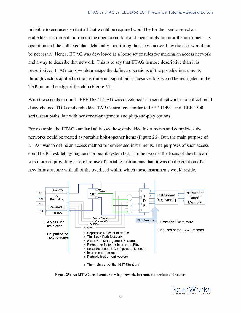
IJTAG vs JTAG vs IEEE 1500 ECT | Technical Tutorial – Second Edition
64
invisible to end users so that all that would be required would be for the user to select an
embedded instrument, hit run on the operational tool and then simply monitor the instrument, its
operation and the collected data. Manually monitoring the access network by the user would not
be necessary. Hence, IJTAG was developed as a loose set of rules for making an access network
and a way to describe that network. This is to say that IJTAG is more descriptive than it is
prescriptive. IJTAG tools would manage the defined operations of the portable instruments
through vectors applied to the instruments’ signal pins. These vectors would be retargeted to the
TAP pin on the edge of the chip (Figure 25).
With these goals in mind, IEEE 1687 IJTAG was developed as a serial network or a collection of
daisy-chained TDRs and embedded TAP Controllers similar to IEEE 1149.1 and IEEE 1500
serial scan paths, but with network management and plug-and-play options.
For example, the IJTAG standard addressed how embedded instruments and complete sub-
networks could be treated as portable bolt-together items (Figure 26). But, the main purpose of
IJTAG was to define an access method for embedded instruments. The purposes of such access
could be IC test/debug/diagnosis or board/system test. In other words, the focus of the standard
was more on providing ease-of-re-use of portable instruments than it was on the creation of a
new infrastructure with all of the overhead within which those instruments would reside.
Figure 25: An IJTAG architecture showing network, instrument interface and vectors

IJTAG vs JTAG vs IEEE 1500 ECT | Technical Tutorial – Second Edition
65
Figure 26: Embedded instrument connections to TAP described in ICL
To make embedded instruments portable would require that their command and data interfaces,
as well as the operations and data applied to their interfaces must be fully described. Embedded
instruments could then be attached to simple TDRs (Figure 27), as opposed to being wrapped in
a complete register architecture including instruction registers as defined by IEEE 1149.1 JTAG
or IEEE 1500 ECT. The operation of these TDRs requires only DR-Scans using the data side of
the IEEE 1149.1 JTAG FSM (Figure 28). All embedded instrument operations and the
configuration of the network can be fully utilized without repeatedly installing instructions in the
IEEE 1149.1 instruction register.

IJTAG vs JTAG vs IEEE 1500 ECT | Technical Tutorial – Second Edition
66
Figure 27: IJTAG architecture with SIBs and NIBs
Figure 28: The active portion of the JTAG FSM for IJTAG operations
The portable IJTAG instrument, once associated with a TDR, can be incorporated into an overall
IEEE 1687 IJTAG network through a daisy-chain connection with other TDRs and the plug-and-
play network interface. To support plug-and-play, the TDR must support a data and control
interface of the following signals: ShiftEn, CaptureEn, UpdateEn, ResetN, Select, TCK, TDI and
TDO.

IJTAG vs JTAG vs IEEE 1500 ECT | Technical Tutorial – Second Edition
67
However, the TDRs don’t necessarily need to be connected in an ever-lengthening daisy-chain,
but can be connected through special network instruction bits (NIBs) known as segment insertion
bits (SIBs), which allow an in-line bypass of the portable instrument TDR with an associated
SIB. In addition, modifications to the access network itself may be incorporated in or near a TDR
associated with an instrument by incorporating other NIBs that would allow the reset, capture
and update operations to be enabled or blocked locally. These network management capabilities
and the configuration of the network are described in IEEE 1687 IJTAG’s Instrument
Connectivity Language (ICL). ICL also allows the description of legacy architectures such as a
plain TDR or even a whole and complete IEEE 1149.1 JTAG or IEEE 1500 ECT architecture.
IJTAG instrument operations would be described in the standard’s Procedure Description
Language (PDL).
Ultimately, this IJTAG access network would be very flexible so that it might incorporate legacy
methods such as IEEE 1149.1 JTAG and IEEE 1500 ECT, as well as newly defined IEEE 1687
IJTAG efficiencies. The IEEE 1687 IJTAG standard allows many different access network
configurations while describing the embedded instrumentation operations in PDL and the
network connections to access the embedded instruments in ICL. This solves one of the main
concerns with IEEE 1149.1 JTAG and IEEE 1500 ECT; namely, the need for scalability to
accommodate the growing number of embedded instruments on ASICs and SoCs.


![HW-SW co-Design of an On-Chip IJTAG Dependability Processoressay.utwente.nl/70623/1/[Master Thesis] HW-SW co-Design of an On-Chip IJTAG... · pendability processor. An on-chip IJTAG](https://img.dokumen.tips/doc/110x75/5d31a73188c99342448bf57f/hw-sw-co-design-of-an-on-chip-ijtag-dependability-master-thesis-hw-sw-co-design.jpg)