Embed Size (px)
Citation preview

Heat and Mass Transfer
Introduction
Sudheer Siddapuredddy
Department of Mechanical EngineeringIndian Institution of Technology Patna
Heat and Mass Transfer Introduction 1 / 393

Course: Heat and Mass Transfer
PrerequisitesThermodynamics, Fluid Mechanics
References
Incropera FP and Dewitt DP, Fundamentals of Heat and MassTransfer, Fifth edition, John Wiley and Sons, 2010.
Cengel YA, Heat and Mass Transfer - A Practical Approach,Third edition, McGraw-Hill, 2010.
Holman JP, Heat Transfer, McGraw-Hill, 1997.
Class Timings: ME305Tue: 9 AM to 10 AM, Room-107
Wed, Thu, Fri: 11 AM to 12 AM, Room-107 Weblinks
www.iitp.ac.in/∼sudheer/teaching.html
Heat and Mass Transfer Introduction 2 / 393
Course Content: Heat and Mass Transfer
Introduction:What, How, and Where?Thermodynamics and HeattransferApplicationPhysical mechanism of heattransfer
Conduction:Introduction1D, steady-state2D, steady-stateTransient
Convection:IntroductionExternal and internal flowsFree convectionBoiling and condensationHeat exchangers
Radiation:IntroductionView factors
Mass Transfer:IntroductionMass diffusion equationTransient diffusion
Heat and Mass Transfer Introduction 3 / 393

Heat Transfer - What?
The science that deals with the determination of the rates ofenergy transfer due to temperature difference.
Driving forceTemperature difference
as the voltage difference in electric currentas the pressure difference in fluid flow
Rate depends on magnitude of dT
Heat and Mass Transfer Introduction 4 / 393

Heat Transfer - How?
Heat and Mass Transfer Introduction 5 / 393

Heat Transfer - Where?
Heat and Mass Transfer Introduction 6 / 393

Heat Transfer - Where else?
Heat and Mass Transfer Introduction 7 / 393

Thermodynamics and Heat Transfer
Thermodynamics
Deals with the amount of energy (heat or work) during a processOnly considers the end states in equilibriumWhy?
Heat Transfer
Deals with the rate of energy transferTransient and non-equilibriumHow long?
Heat and Mass Transfer Introduction 8 / 393

Thermodynamics and Heat Transfer
Laws of Thermodynamics
Zeroth law - TemperatureFirst law Energy conservedSecond law EntropyThird law S → constant as T → 0
Laws of Heat Transfer
Fouriers law - ConductionNewtons law of cooling - ConvectionStephan-Boltzmann law - Radiation
Heat and Mass Transfer Introduction 9 / 393

Heat Transfer - History
Caloric theory (18th Century)Heat is a fluid like substance, ‘caloric ’ poured from one bodyinto another.Caloric: Massless, colorless, odorless, tasteless
Heat and Mass Transfer Introduction 10 / 393

Heat Transfer - History
Kinetic theory (19th Century)Molecules - tiny balls - are in motion possessing kinetic energyHeat: The energy associated with the random motion of atomsand molecules
Heat and Mass Transfer Introduction 11 / 393

Heat, Rate, Flux
HeatThe amount of heat transferred during a process, Q
Heat transfer rateThe amount of heat transferred per unit time, Q or simply q
Q =
∫ ∆t
0qdt
Q = q∆t, if q is constant
Heat fluxThe rate of heat transfer per unit area normal to the directionof heat transfer:
q′′ =q
A
Heat and Mass Transfer Introduction 12 / 393

Heat, Rate, Flux
q′′ =24 W
6 m2= 4 W/m2
Heat and Mass Transfer Introduction 13 / 393

Conduction - Macroscopic View
Viewed asThe transfer of energy from the more energetic to the lessenergetic particles of a substance due to interactions betweenthe particles.Net transfer by random molecules motion - diffusion of energy
Heat and Mass Transfer Introduction 14 / 393

Conduction: Fourier’s Law of Heat Conduction
qcond = −kAT1 − T2
∆x= −kAdT
dx
Heat and Mass Transfer Introduction 15 / 393

Problem: Conduction
The wall of an industrial furnace is constructed from 0.15 m thickfireclay brick having a thermal conductivity of 1.7 W/m K.Measurements made during steady-state operation revealtemperatures of 1400 and 1150 K at the inner and outer surfaces,respectively. What is the rate of heat loss through a wall that is0.5 × 1.2 m2 on a side?
Ans: 1.7 kW
Heat and Mass Transfer Introduction 16 / 393

Convection
Comprised of two mechanismsEnergy transfer due to random molecular motion - diffusionEnergy transfer by the bulk motion of the fluid - advection
Boundary layer development in convection heat transfer
Heat and Mass Transfer Introduction 17 / 393

Convection - Classification
Forced and Free/Natural Convection
Boiling and Condensation
Heat and Mass Transfer Introduction 18 / 393

Convection: Newton’s Law of Cooling
qconv = hAs (Ts − T∞)
Process h (W/m2 K)
Free convectionGases 2-25
Liquids 50-1000
Convection with phase changeBoiling and Condensation 2500-100,000
Heat and Mass Transfer Introduction 19 / 393

Thermal Radiation
RadiationEnergy emitted by matter that is at a nonzero temperatureTransported by electromagnetic waves (or photons)Medium?
Surface Emissive PowerThe rate at which energy is released per unit area (W/m2)
Eb = σT 4s
Heat and Mass Transfer Introduction 20 / 393

Radiation: Stefan-Boltzmann Law
For a real surface:
E = εσT 4s
q′′rad = εσ(T 4s − T 4
sur
)Heat and Mass Transfer Introduction 21 / 393

First Law of Thermodynamics
Ein − Eout = ∆Est
In rate form:
Ein − Eout =dEstdt
= Est
Heat and Mass Transfer Introduction 22 / 393

First Law of Thermodynamics
The inflow and outflow terms are surface phenomena.The energy generation term is a volumetric phenomenon.
chemical, electricalThe energy storage is also a volumetric phenomenon.
∆U + ∆KE + ∆PE∆U : sensible/thermal, latent, and chemical components
Heat and Mass Transfer Introduction 23 / 393

First Law of Thermodynamics
Steady state with no heat generation
Heat and Mass Transfer Introduction 24 / 393

Surface Energy Balance
Ein − Eout = 0qcond − qconv − qrad = 0
Heat and Mass Transfer Introduction 25 / 393

Problem Solving: Methodology
Analysis of different problems will give a deeper appreciation forthe fundamentals of the subject, and you will gain confidence inyour ability to apply these fundamentals to the solution ofengineering problems.Be consistent in following these steps:
1 known
2 Find
3 Schematic
4 Assumptions
5 Properties
6 Analysis
7 Comments
Heat and Mass Transfer Introduction 26 / 393

Problem: Conduction
The hot combustion gases of a furnace are separated from theambient air and its surrounding, which are at 25◦C, by a brick wall0.15 m thick. The brick has a thermal conductivity of 1.2 W/m Kand a surface emissivity of 0.8. Under steady-state conditions anouter surface temperature of 100◦C is measured. Free convectionheat transfer to the air adjoining the surface is characterized by aconvection coefficient of 20 W/m2 K. What is the brick innersurface temperature.
Ans: 625 K
Heat and Mass Transfer Introduction 27 / 393

Problem: Convection
An experiment to determine the convection coefficient associatedwith airflow over the surface of a thick stainless steel castinginvolves the insertion of thermocouples into the casting atdistances of 10 and 20 mm from the surface along a hypotheticalline normal to the surface. The steel has a thermal conductivity of15 W/m K. If the thermocouples measure temperatures of 50 and40◦C in the steel when the air temperature is 100◦C, what is theconvection coefficient?
Ans: 375 W/m2 K
Heat and Mass Transfer Introduction 28 / 393
Problem: Radiation
The roof of a car in a parking lot absorbs a solar radiant flux of800 W/m2, and the underside is perfectly insulated. Theconvection coefficient between the roof and the ambient air is12 W/m2 K.
a) Neglecting radiation exchange with the surroundings, calculatethe temperature of the roof under steady-state conditions if theambient air temperature is 20◦C.
b) For the same ambient air temperature, calculate thetemperature of the roof if its surface emissivity is 0.8.
c) The convection coefficient depends on air flow conditions overthe roof, increasing with increasing air speed. Compute andplot the roof temperature as a function of h for2 ≤ h ≤ 200 W/m2 K.
Ans: 86.7◦C
Heat and Mass Transfer Introduction 29 / 393

Heat and Mass Transfer
Heat Diffusion Equation
Sudheer Siddapuredddy
Department of Mechanical EngineeringIndian Institution of Technology Patna
Heat and Mass Transfer Heat Diffusion Equation 30 / 393

Steady-state vs Transient
Fourier’s law of heat conduction
qcond = −kAdTdx
transientmultidimensional - complex geometries
Steady-state heat transfer
No change with time at anypoint within the medium
T and q′′ remainsunchanged with time
T = T (x, y, z)
Usually no but assumed
Transient heat transfer
Time dependence
T = T (x, y, z, t)
Special case - lumped - Tchanges with time but notwith location:
T = T (t)
Heat and Mass Transfer Heat Diffusion Equation 31 / 393

Coordinate System
Heat and Mass Transfer Heat Diffusion Equation 32 / 393

Multidimensional Heat Transfer
Heat and Mass Transfer Heat Diffusion Equation 33 / 393

Heat Flux Direction
The direction of heat flow will always benormal to a surface of constanttemperature, called an isothermal surface.
q′′x = −k∂T∂x
; q′′y = −k∂T∂y
; q′′z = −k∂T∂z
q′′n = q′′x~i+ q′′y~j + q′′z~k
= −k(∂T
∂x~i+
∂T
∂y~j +
∂T
∂z~k
)= −k∇T
where n is the normal of the isothermalsurface and
q′′n = −k∂T∂n
Heat and Mass Transfer Heat Diffusion Equation 34 / 393

Thermal Conductivity
Thermal conductivity
k =q′′
(∂T/∂x)
The rate of heat transfer through a unit thickness of the materialper unit area per unit temperature difference.
Specific heat, Cp
Ability to store thermal energy.At room temperature,
Cp = 4.18 kJ/kg K, water
= 0.45 kJ/kg K, iron
Thermal conductivity, k
Material’s ability to conduct heatAt room temperature,
k = 0.607 W/m K, water
= 80.2 W/m K, iron
Heat and Mass Transfer Heat Diffusion Equation 35 / 393

Thermal Conductivity
Transport property
Indication of the rate at which energy is transferred by thediffusion process
Depends on the physical structure of matter, atomic andmolecular, related to the state of the matter
Isotropic material - k is independent of the direction oftransfer, kx = ky = kz
Laminated composite materials and wood
k across grain is different than that parallel to grain
Heat and Mass Transfer Heat Diffusion Equation 36 / 393

k for Different Materials at T∞ and P∞
Kinetic theory of gases:
vrms =√
3RTM
T ↑ k ↑M ↑ k ↓
He(4), Air(29)
Liquids: Strongintermolecular forces
Most liquids: T ↑ k ↓M ↑ k ↓
Except water: Not a lineartrend
Heat and Mass Transfer Heat Diffusion Equation 37 / 393

k - Temp. Dependency
Temp. dependencycauses considerablecomplexity inconduction analysis
kaverage
Heat and Mass Transfer Heat Diffusion Equation 38 / 393

k for Solids
k = kl + ke
High k for pure metals is due to kekl depends on the way the moleculesare arranged
Diamond - highly ordered crystalline solidHighest known kHowever a poor electric conductor (even semiconductors likesilicon)Diamond heat sinks - cooling electronic components
Heat and Mass Transfer Heat Diffusion Equation 39 / 393

k for Alloys
Pure metals have high k
kiron = 83 W/m K
kchromium = 95 W/m K
Steel is iron + 1% chrome
ksteel = 62 W/m K
Alloy of two metals k1 and k2 < k1 and k2
Heat and Mass Transfer Heat Diffusion Equation 40 / 393

Thermal Diffusivity α
Thermophysical properties
k Transport property
ρ, Cp Thermodynamic properties
ρCp is volumetric heat capacity (J/m3 K)
High α: faster propagation of heat into the medium
Small α: heat is mostly absorbed by the material and a smallamount of heat is conducted further
Heat and Mass Transfer Heat Diffusion Equation 41 / 393

Heat Diffusion Equation: Application
Problem and application
Determine temperature distribution in a medium resultingfrom conditions imposed on its boundaries
The conduction heat flux at any point in the medium or onthe surface may be computed from Fourier’s law
This information could be used to determine thermal stresses,expansions, deflections
Temperature distribution may also be used to optimize thethickness of an insulating material or to determine thecompatibility of special coatings or adhesives used with thematerial
Heat and Mass Transfer Heat Diffusion Equation 42 / 393

Control Volume
Assumptions
Homogeneous medium No bulk motion (advection)
Schematic
Consider an infinitesimally small (differential) CV, dx.dy.dz
qx+dx = qx +∂qx∂x
dx
qy+dy = qy +∂qy∂y
dy
qz+dz = qz +∂qz∂z
dz
Heat and Mass Transfer Heat Diffusion Equation 43 / 393
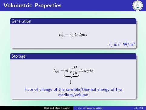
Volumetric Properties
Generation
Eg = egdxdydz
eg is in W/m3
Storage
Est = ρCp∂T
∂t︸ ︷︷ ︸ dxdydz↓
Rate of change of the sensible/thermal energy of themedium/volume
Heat and Mass Transfer Heat Diffusion Equation 44 / 393

Heat Diffusion Equation
Governing Equation
Ein − Eout + Eg = Est
qx + qy + qz − qx+dx − qy+dy − dz+dz + egdxdydz = ρCp∂T
∂tdxdydz
−∂qx∂x
dx− ∂qy∂y
dy − ∂qz∂z
dz + egdxdydz = ρCp∂T
∂tdxdydz
However,
qx = −kdydz ∂T∂x
; qy = −kdxdz∂T∂y
; qz = −kdxdy∂T∂z
∂
∂x
(k∂T
∂x
)+
∂
∂y
(k∂T
∂y
)+
∂
∂z
(k∂T
∂z
)+ eg = ρCp
∂T
∂t
Heat and Mass Transfer Heat Diffusion Equation 45 / 393

Special Cases
Fourier-Biot equation - Isotropic
∂2T
∂x2+∂2T
∂x2+∂2T
∂x2+egk
=1
α
∂T
∂t
Diffusion equation - Transient, no heat generation
∂2T
∂x2+∂2T
∂x2+∂2T
∂x2=
1
α
∂T
∂t
Poisson equation - Steady-state
∂2T
∂x2+∂2T
∂x2+∂2T
∂x2+egk
= 0
Laplace equation - Steady-state, no heat generation
∂2T
∂x2+∂2T
∂x2+∂2T
∂x2= 0
Heat and Mass Transfer Heat Diffusion Equation 46 / 393

Coordinate Systems
Cartesian coordinates T (x, y, z)
∂
∂x
(k∂T
∂x
)+
∂
∂y
(k∂T
∂y
)+
∂
∂z
(k∂T
∂z
)+ eg = ρCp
∂T
∂t
Cylindrical coordinates T (r, φ, z)
1
r
(kr∂T
∂r
)+
1
r2
∂
∂φ
(k∂T
∂φ
)+
∂
∂z
(k∂T
∂z
)+ eg = ρCp
∂T
∂t
Spherical coordinates T (r, φ, θ)
1
r2
∂
∂r
(kr2∂T
∂r
)+
1
r2 sin2 θ
∂
∂φ
(k∂T
∂φ
)+
1
r2 sin θ
∂
∂θ
(k sin θ
∂T
∂θ
)+ eg = ρCp
∂T
∂t
Heat and Mass Transfer Heat Diffusion Equation 47 / 393

Boundary and Initial Conditions
Necessary to solve the appropriate form of the heat equation
Depends on the physical conditions at boundaries
On time
Boundary conditions can be simply expressed in mathematicalform
Second order in space, two boundary conditions for eachcoordinate needed to describe the system
First order in time, only one condition, initial conditionmust be specified
Heat and Mass Transfer Heat Diffusion Equation 48 / 393

Boundary Conditions at x = 0
Heat and Mass Transfer Heat Diffusion Equation 49 / 393

Problem: Diffusion Equation
A long copper bar of rectangular cross section, whose width w ismuch greater than its thickness L, is maintained in contact with aheat sink at its lower surface, and the temperature throughout thebar is approximately equal to that of the sink, To. Suddenly, anelectric current is passed through the bar and an airstream oftemperature T∞ is passed over the top surface, while the bottomsurface continues to be maintained at To. Obtain the differentialequation and the boundary and initial conditions that could besolved to determine the temperature as a function of position andtime in the bar.
Heat and Mass Transfer Heat Diffusion Equation 50 / 393
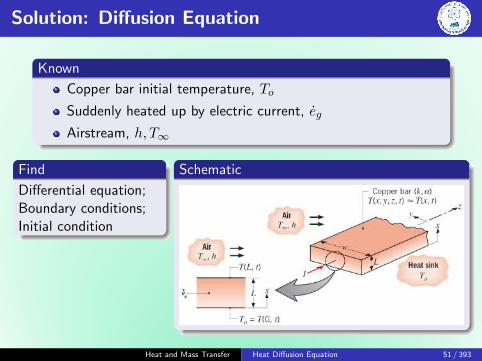
Solution: Diffusion Equation
Known
Copper bar initial temperature, To
Suddenly heated up by electric current, eg
Airstream, h, T∞
Find
Differential equation;Boundary conditions;Initial condition
Schematic
Heat and Mass Transfer Heat Diffusion Equation 51 / 393

Solution: Diffusion Equation
Assumptions
w � L - side effects are neglected. Thus heat transfer isprimarily one dimensional (x)
Uniform volumetric heat generation, eg
Constant properties
Analysis
∂2T
∂x2+egk
=1
α
∂T
∂t
Boundary conditions
T (0, t) = To
−k∂T∂x|x=L = h [T (L, t)− T∞]
Initial condition
T (x, 0) = To
Heat and Mass Transfer Heat Diffusion Equation 52 / 393

Solution: Diffusion Equation
Comments
1 If To, T∞, eg, and h are known, then the equations can besolved to obtain the T (x, t)
2 Top surface, T (L, t) will change with time. This is unknownand may be obtained after finding T (x, t)
Heat and Mass Transfer Heat Diffusion Equation 53 / 393

Solution: Diffusion Equation
Heat and Mass Transfer Heat Diffusion Equation 54 / 393

Heat and Mass Transfer
One-Dimensional, Steady-State Conduction
Sudheer Siddapuredddy
Department of Mechanical EngineeringIndian Institution of Technology Patna
Heat and Mass Transfer 1D, Steady-State Conduction 55 / 393

One-Dimensional, Steady-State
Temp. gradients exist along only a single coordinate direction
Heat transfer occurs exclusively in that direction
Temp. at each point is independent of time
We will see:
Temp. distribution & heat transfer rate in common (planar,cylindrical and spherical) geometries
Thermal resistance
Thermal circuits to model heat flowElectrical circuits to current flow
Heat and Mass Transfer 1D, Steady-State Conduction 56 / 393

Cartesian Coordinates: T (x)
d
dx
(kdT
dx
)= 0
For 1-D, steady-state conductionin a plane wall with no heatgeneration, heat flux is aconstant, independent of x.
Heat and Mass Transfer 1D, Steady-State Conduction 57 / 393
Plane Wall
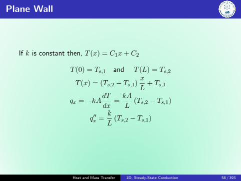
If k is constant then, T (x) = C1x+ C2
T (0) = Ts,1 and T (L) = Ts,2
T (x) = (Ts,2 − Ts,1)x
L+ Ts,1
qx = −kAdTdx
=kA
L(Ts,2 − Ts,1)
q′′x =k
L(Ts,2 − Ts,1)
Heat and Mass Transfer 1D, Steady-State Conduction 58 / 393

Thermal Resistance
Ratio of driving potential to the corresponding transfer rate
Rt,cond =(Ts,1 − Ts,2)
qx=
L
kA
Re =Es,1 − Es,2
I
Rt,conv =(Ts − T∞)
q=
1
hA
Under steady state condi-
tions:Convection rateinto the wall
= Conduction ratethrough the wall
= Convection ratefrom the wall
qx =T∞,1 − Ts,1
1/h1A=Ts,1 − Ts,2L/kA
=Ts,2 − T∞,2
1/h2A
qx =T∞,1 − T∞,2
RtotRtot =
1
h1A+
L
kA+
1
h2A
Heat and Mass Transfer 1D, Steady-State Conduction 59 / 393

Thermal Resistance: Radiation
The thermal resistance for radiation - radiation exchangebetween the surface and its surroundings:
Rt,rad =Ts − Tsurqrad
=1
hrA
qrad = hrA (Ts − Tsur)The radiation heat transfer coefficient, hr:
hr = εσ (Ts + Tsur)(T 2s + T 2
sur
)
Heat and Mass Transfer 1D, Steady-State Conduction 60 / 393

The Composite Wall
Heat and Mass Transfer 1D, Steady-State Conduction 61 / 393

The Composite Wall
qx =T∞,1 − T∞,4∑
Rt
Rtot =1
h1A+
LAkAA
+LBkBA
+LCkCA
+1
h4A
If U is the overall heat transfer coefficient
qx = UA∆T
U =1
RtotA
Heat and Mass Transfer 1D, Steady-State Conduction 62 / 393

Series-Parallel Composite Wall
Heat and Mass Transfer 1D, Steady-State Conduction 63 / 393

Contact Resistance
R′′t,c =TA − TB
q′′x
Heat and Mass Transfer 1D, Steady-State Conduction 64 / 393

Thermal Resistance of Solid/Solid Interfaces
Heat and Mass Transfer 1D, Steady-State Conduction 65 / 393

Porous Medium
For a porous medium, an effective conductivity is considered.Assuming, there is no fluid bulk motion and if T1 > T2
qx =keffA
L(T1 − T2)
Heat and Mass Transfer 1D, Steady-State Conduction 66 / 393
The Cylinder
Heat and Mass Transfer 1D, Steady-State Conduction 67 / 393
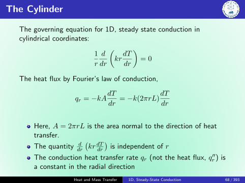
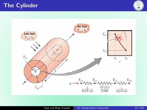
The Cylinder
The governing equation for 1D, steady state conduction incylindrical coordinates:
1
r
d
dr
(krdT
dr
)= 0
The heat flux by Fourier’s law of conduction,
qr = −kAdTdr
= −k(2πrL)dT
dr
Here, A = 2πrL is the area normal to the direction of heattransfer.
The quantity ddr
(kr dTdr
)is independent of r
The conduction heat transfer rate qr (not the heat flux, q′′r ) isa constant in the radial direction
Heat and Mass Transfer 1D, Steady-State Conduction 68 / 393

The Cylinder
Temperature distribution and heat transfer rate
T (r) =Ts,1 − Ts,2ln(r1/r2)
ln
(r
r2
)+ Ts,2
Note that the temperature distribution associated with radialconduction through a cylindrical wall is logarithmic, not linear, asit is for the plane wall.
qr =2πLk (Ts,1 − Ts,2)
ln(r2/r1)
Note that qr is independent of r.
Rt,cond =ln(r2/r1)
2πLk
Heat and Mass Transfer 1D, Steady-State Conduction 69 / 393

The Cylinder
Heat and Mass Transfer 1D, Steady-State Conduction 70 / 393

The Cylinder
qr =(T∞,1 − T∞,2)
12πr1Lh1
+ ln(r2/r1)2πkAL
+ ln(r3/r2)2πkBL
+ ln(r4/r3)2πkCL
+ 12πr4Lh4
qr =(T∞,1 − T∞,2)
Rtot= UA (T∞,1 − T∞,2)
If U is defined in terms of the inside area, A1 = 2πr1L, then:
U =1
1h1
+ r1kA
ln( r2r1 ) + r1kB
ln( r3r2 ) + r1kC
ln( r4r3 ) + r1r4
1h4
UA is constant, while U is not
In radial systems, q is constant, while q′′ is not
Heat and Mass Transfer 1D, Steady-State Conduction 71 / 393

The Sphere
Consider a hollow sphere, whose inner and outer surfaces areexposed to fluids at different temperatures.
1
r2
d
dr
(kr2dT
dr
)= 0
qr = −k(4πr2)dT
dr
Heat and Mass Transfer 1D, Steady-State Conduction 72 / 393

The Sphere
Temperature distribution and heat transfer rate
T (r) = Ts,1 +Ts,1 − Ts,2(
1r2− 1
r1
) [ 1
r1− 1
r
]
qr =4πk (Ts,1 − Ts,2)(
1r1− 1
r2
)Rt,cond =
1
4πk
(1
r1− 1
r2
)
Heat and Mass Transfer 1D, Steady-State Conduction 73 / 393

Problem: Sphere
A spherical thin walled metallic container is used to store liquidnitrogen at 80 K. The container has a diameter of 0.5 m and iscovered with an evacuated, reflective insulation composed of silicapowder. The insulation is 25 mm thick, and its outer surface isexposed to ambient air at 310 K. The convection coefficient isknown to be 20 W/m2 K. The latent heat of vaporization and thedensity of the liquid nitrogen are 2× 10⁵ J/kg and 804 kg/m3,respectively. Thermal conductivity of evacuated silica powder(300 K) is 0.0017 W/m K.
1 What is the rate of heat transfer to the liquid nitrogen?
2 What is the rate of liquid boil-off?
Heat and Mass Transfer 1D, Steady-State Conduction 74 / 393

Solution: Sphere
known
Liquid nitrogen is stored in a spherical container that is insulatedand exposed to ambient air.
Find
The rate of heat transfer to the nitrogen.
The mass rate of nitrogen boil-off.
Schematic
Heat and Mass Transfer 1D, Steady-State Conduction 75 / 393

Solution: Sphere
Assumptions
1 Steady state conditions
2 One-dimensional transfer in the radial direction
3 Negligible resistance to heat transfer through the containerwall and from the container to the nitrogen
4 Constant properties
5 Negligible radiation exchange between outer surface ofinsulation and surroundings
Analysis
Rt,cond Rt,convqr
Heat and Mass Transfer 1D, Steady-State Conduction 76 / 393

Solution: Analysis
Rt,cond =1
4πk
(1
r1− 1
r2
)Rt,conv =
1
h(4πr2
2
)qr =(T∞,2 − T∞,1)
Rt,cond +Rt,conv= 12.88W
Energy balance for a control surface about the nitrogen:
Ein − Eout = 0
q − mhfg = 0
=⇒ m = 6.44× 10⁻⁵ kg/W
= 5.56 kg/day
=m
ρ= 0.00692 m3/day
= 6.92 liters/day
Heat and Mass Transfer 1D, Steady-State Conduction 77 / 393

The Critical Radius of Insulation
We know that by adding more insulation to a wall alwaysdecreases heat transfer.
This is expected, since the heat transfer area A is constant,and adding insulation will always increase the thermalresistance of the wall without affecting the convectionresistance.
However, adding insulation to a cylindrical piece or a sphericalshell, is a different matter.
The additional insulation increases the conduction resistanceof the insulation layer but it also decreases the convectionresistance of the surface because of the increase in the outersurface area for convection.
Therefore, the heat transfer from a pipe may increase ordecrease, depending on which effect dominates.
Heat and Mass Transfer 1D, Steady-State Conduction 78 / 393

The Critical Radius of Insulation
Heat and Mass Transfer 1D, Steady-State Conduction 79 / 393

The Critical Radius of Insulation
The rate of heat transfer from the insulated pipe to thesurrounding air can be expressed as:
qr =(T1 − T∞)
ln(r2r1
)2πLk + 1
h(2πr2L)
The value of r2 at which heat transferrate reaches max. is determined fromthe requirement that dqr
dr (zero slope):
rcr,cylinder =k
h
Heat and Mass Transfer 1D, Steady-State Conduction 80 / 393

Problem: Critical Radius
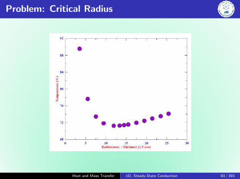
A 3 mm diameter and 6 m long electric wire is tightly wrappedwith a 2 mm thick plastic cover whose thermal conductivity isk = 0.15 W/m K. Electrical measurements indicate that a currentof 10 A passes through the wire and there is a voltage drop of 8 Valong the wire. If the insulated wire is exposed to a medium at27◦C with a heat transfer coefficient of h = 12 W/m2 K,determine the temperature at the interface of the wire and theplastic cover in steady operation. Also determine whether doublingthe thickness of the plastic cover will increase or decrease thisinterface temperature. Ans: 89.5◦C, 77.5◦C
Hint: qr = V I
Heat and Mass Transfer 1D, Steady-State Conduction 81 / 393

Problem: Critical Radius
Heat and Mass Transfer 1D, Steady-State Conduction 82 / 393
Problem: Critical Radius
Heat and Mass Transfer 1D, Steady-State Conduction 83 / 393

Overall
Heat and Mass Transfer 1D, Steady-State Conduction 84 / 393

Conduction with Thermal Energy Generation
A very common thermal energy generation process involves theconversion from electrical to thermal energy in a current carryingmedium (resistance heating). The rate at which energy isgenerated by passing a current through a medium of electricalresistance Re is:
Eg = I2Re
If this power generation occurs uniformly throughout the mediumof volume V , the volumetric generation rate (W/m3) is:
q =EgV
=I2ReV
Heat and Mass Transfer 1D, Steady-State Conduction 85 / 393

Conduction with Eg in a Plane Wall
Consider a plane wall, in which there is uniform energy generationper unit volume (q is constant) and the surfaces are maintained atTs,1 and Ts,2. The appropriate form of the heat equation:
d2T
dx2+q
k= 0
∣∣∣∣∣∣T (−L) = Ts,1
T (L) = Ts,2
Heat and Mass Transfer 1D, Steady-State Conduction 86 / 393
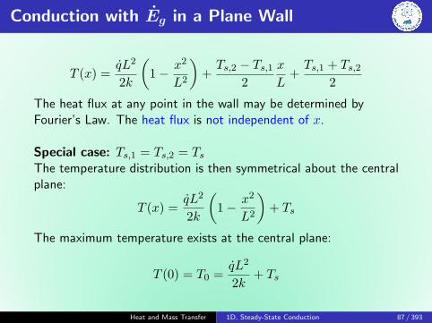
Conduction with Eg in a Plane Wall
T (x) =qL2
2k
(1− x2
L2
)+Ts,2 − Ts,1
2
x
L+Ts,1 + Ts,2
2
The heat flux at any point in the wall may be determined byFourier’s Law. The heat flux is not independent of x.
Special case: Ts,1 = Ts,2 = TsThe temperature distribution is then symmetrical about the centralplane:
T (x) =qL2
2k
(1− x2
L2
)+ Ts
The maximum temperature exists at the central plane:
T (0) = T0 =qL2
2k+ Ts
Heat and Mass Transfer 1D, Steady-State Conduction 87 / 393

Conduction with Eg in a Plane Wall
T (x)− T0
Ts − T0=(xL
)2
It is important to note that the temperature gradientdTdx |x=0 = 0 at the plane of symmetry.
No heat transfer across this plane - adiabatic surface.
The above equation can also be applied to plane walls thatare perfectly insulated on one side (x = 0) and a fixed Ts onthe other side (x = L).
However, in most of the cases, Ts is an unknown. It is computedfrom the energy balance at the surface to the adjoining fluid:
−k dTdx
∣∣∣∣x=L
= h(Ts − T∞)
=⇒ Ts = T∞ +qL
h
Heat and Mass Transfer 1D, Steady-State Conduction 88 / 393

Conduction with Eg in Radial Systems
Consider a long, solid cylinder (may be a current carrying wire).For steady state conditions: Eg = qconv.
Heat and Mass Transfer 1D, Steady-State Conduction 89 / 393

Conduction with Eg in Radial Systems
1
r
d
dr
(rdT
dr
)+q
k= 0
Boundary conditions:
dT
dr
∣∣∣∣r=0
= 0, T (R) = Ts and T (r = 0) = T0
=⇒ T (r) = Ts +qR2
4k
(1− r2
R2
)or
T (r)− TsT0 − Ts
= 1−( rR
)2
Ts can be obtained from the energy balance at the surface:
q πR2L = h 2πRL (Ts − T∞)
Ts = T∞ +qR
2h
Heat and Mass Transfer 1D, Steady-State Conduction 90 / 393

Problem
Consider one-dimensional conduction in a plane composite wall.The outer surfaces are exposed to a fluid at 25◦C and a convectionheat transfer coefficient of 1000 W/m2 K. The middle wall Bexperiences uniform heat generation qB, while there is nogeneration in walls A and C. The temperatures at the interfacesare T1 = 261◦C and T2 = 211◦C. Assuming negligible contactresistance at the interfaces, determine qB and kB.
Ans: 4× 10⁶ W/m3, 15.3 W/m K.
Heat and Mass Transfer 1D, Steady-State Conduction 91 / 393

Solution
From an energy balance on wall B,
Ein− Eout+ Eg = Est
−qA − qC + ˙qBV = 0
=⇒ −q′′A − q′′C + ˙qB 2LB = 0
qB =qA + qC
2LBHeat flow across ambient and wall A:
q′′A =T1 − T∞(1h + LA
kA
) =261− 25
11000 + 30×10−3
25
= 107272.7 W/m2
Heat and Mass Transfer 1D, Steady-State Conduction 92 / 393

Solution
Heat flow across ambient and wall C:
q′′C =T1 − T∞(1h + LC
kC
) =211− 25
11000 + 20×10−3
50
= 132857.1 W/m2
qB =qA + qC
2LB=
107272.7 + 132857.1
60× 10−3= 4× 10⁶ W/m3
Heat and Mass Transfer 1D, Steady-State Conduction 93 / 393

Solution
T (x) =qBL
2B
2kB
(1− x2
L2B
)+T2 − T1
2
x
LB+T1 + T2
2
q′′B(x) = −kB[qB
2kB(−2x) +
T2 − T1
2LB
]
q′′B∣∣x=−LB
= −qBLB −T2 − T1
2LBkB
kB =−q′′A + qBLB
(T1 − T2)/2LB= 15.35 W/m K
Heat and Mass Transfer 1D, Steady-State Conduction 94 / 393

Problem
A plane wall is a composite of two materials, A and B. The wall ofmaterial A has uniform heat generation q = 1.5× 10⁶ W/m3,kA = 75 W/m K, and thickness LA = 50 mm. The wall material Bhas no generation with kB = 150 W/m K, and thicknessLB = 20 mm. The inner surface of material A is well insulated,while the outer surface of material B is cooled by a water streamwith T∞ = 30◦C and = 1000 W/m2 K.
Sketch the temperature distribution that exists in thecomposite under steady state conditions.
Determine the temperature T0 of the insulated surface andthe temperature T2 of the cooled surface.
Heat and Mass Transfer 1D, Steady-State Conduction 95 / 393

Heat and Mass Transfer
1D Heat Transfer from Extended Surfaces - Fins
Sudheer Siddapuredddy
Department of Mechanical EngineeringIndian Institution of Technology Patna
Heat and Mass Transfer Fins 96 / 393

Heat Transfer from Extended Surfaces
Extended surface: solid that experiences energy transfer byconduction within its boundaries, as well as energy transfer byconvection and/or radiation between its boundaries and thesurround-
ings. Astrut is used to provide mechanical support to two walls atdifferent T . A temperature gradient in the x-direction sustainsheat transfer by conduction internally, at the same time there isenergy transfer by convection from the surface.
Heat and Mass Transfer Fins 97 / 393

Heat Transfer from Extended Surfaces
The most frequent application is one in which an extended surfaceis used specifically to enhance the heat transfer rate between asolid and an adjoining fluid - called as fin
Consider a plane wall:
qconv = hA(Ts − T∞)
Heat and Mass Transfer Fins 98 / 393
Heat Transfer from Extended Surfaces
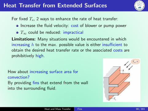
For fixed Ts, 2 ways to enhance the rate of heat transfer:
Increase the fluid velocity: cost of blower or pump power
T∞ could be reduced: impractical
Limitations: Many situations would be encountered in whichincreasing h to the max. possible value is either insufficient toobtain the desired heat transfer rate or the associated costs areprohibitively high.
How about increasing surface area forconvection?By providing fins that extend from the wallinto the surrounding fluid.
Heat and Mass Transfer Fins 99 / 393

Fin Material
k of the fin material has a strong effect on the temperaturedistribution along the fin and therefore influences the degreeto which the heat transfer rate is enhanced.
Ideally, the fin material should have a large k to minimizetemperature variations from its base to its tip.
In the limit of infinite thermal conductivity, the entire finwould be at the temperature of the base surface, therebyproviding the maximum possible heat transfer enhancement.
Heat and Mass Transfer Fins 100 / 393

Application of Fins
The arrangement for cooling engine heads on motorcycles andlawn-mowers
For cooling electric power transformers
The tubes with attached fins used to promote heat exchangebetween air and the working fluid of an air conditioner
Heat and Mass Transfer Fins 101 / 393

Typical Finned Tube Heat Exchangers
Heat and Mass Transfer Fins 102 / 393

Fin Configurations
For an extended surface, the direction of heat transfer from theboundaries is perpendicular to the principal direction of heattransfer in the solid.
Heat and Mass Transfer Fins 103 / 393

General Conduction Analysis
To determine the heat transfer rate associated with a fin, we mustfirst obtain the temperature distribution along the fin.
Heat and Mass Transfer Fins 104 / 393

Assumptions
1-D heat transfer (longitudinal x direction). In practice thefine is thin and the temperature changes in the longitudinaldirection are much larger than those in the transversedirection.
Steady state
k is constant
No heat generation
Negligible radiation from the surface
The rate at which the energy is convected to the fluid fromany point on the fin surface must be balanced by the rate atwhich the energy reaches that point due to conduction in thetransverse (y, z) direction.
h is uniform over the surface
Heat and Mass Transfer Fins 105 / 393
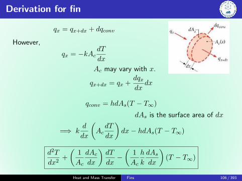
Derivation for fin
qx = qx+dx + dqconv
However,
qx = −kAcdT
dx
Ac may vary with x.
qx+dx = qx +dqxdx
dx
qconv = hdAs(T − T∞)
dAs is the surface area of dx
=⇒ kd
dx
(AcdT
dx
)dx− hdAs(T − T∞)
d2T
dx2+
(1
Ac
dAcdx
)dT
dx−(
1
Ac
h
k
dAsdx
)(T − T∞)
Heat and Mass Transfer Fins 106 / 393

Fins of Uniform Cross-Sectional Area
T (0) = Tb
Ac is constant, dAc/dx = 0
As = Px where x is measured from base, P is fin perimeter
dAs/dx = P
d2T
dx2− hP
kAc(T − T∞) = 0
Heat and Mass Transfer Fins 107 / 393

Fins of Uniform Cross-Sectional Area
Excess temperature, θ
θ(x) = T (x)− T∞
dθ/dx = dT/dx
d2θ
dx2−m2θ = 0
where m2 = hPkAc
The above equation is a linear, homogeneous, second-orderdifferential equation with constant coefficients. The generalsolution is of the form:
θ(x) = C1emx + C2e
−mx
It is necessary to specify appropriate BCs for C1 and C2.Heat and Mass Transfer Fins 108 / 393

Fins of Uniform Cross-Sectional Area
One such condition may be specified in terms of the temperatureat the base of the fin (x = 0):
θ(0) = Tb − T∞ = θb
The second condition, specified at the fin tip (x = L), maycorrespond to any one of the four different physical conditions:
A. h at the fin tip
B. Adiabatic condition at the fin tip
C. Prescribed temperature maintained at the fin tip
D. Infinite fin (very long fin)
Heat and Mass Transfer Fins 109 / 393

Fins of Uniform Cross-Sectional Area
A. Infinite fin (very long fin): As L→∞, θL → 0
B. Adiabatic condition at the fin tip
dθ
dx
∣∣∣∣x=L
= 0
C. h at the fin tip
hAc[T (L)−T∞] = −kAc dTdx
∣∣∣∣x=L
=⇒ hθ(L) = −k dθdx
∣∣∣∣x=L
D. Prescribed temperature maintained at the fin tip: θ(L) = θL
Heat and Mass Transfer Fins 110 / 393

Case A: Infinite fin (very long fin)
As L→∞, θL → 0 and e−mL → 0
θ|x=0 = θb; θ|x=L = 0
θb = C1emx + C2e
−mx; C1emL + C2e
−mL = 0
Equation for infinite fin
θ
θb= e−mx
qf = −kAcdθ
dx
∣∣∣∣x=0
=√hPkAcθb
Heat and Mass Transfer Fins 111 / 393
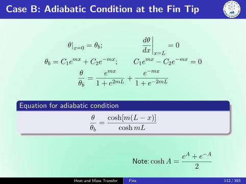
Case B: Adiabatic Condition at the Fin Tip
θ|x=0 = θb;dθ
dx
∣∣∣∣x=L
= 0
θb = C1emx + C2e
−mx; C1emx − C2e
−mx = 0
θ
θb=
emx
1 + e2mL+
e−mx
1 + e−2mL
Equation for adiabatic condition
θ
θb=
cosh[m(L− x)]
coshmL
Note: coshA =eA + e−A
2
Heat and Mass Transfer Fins 112 / 393

Case B: Adiabatic Condition at the Fin Tip
qf = −kAcdT
dx
∣∣∣∣x=0
= −kAcdθ
dx
∣∣∣∣x=0
= −kAc mθb
[1
1 + e2mL− 1
1 + e−2mL
]=√hPkAcθb
[emL − e−mL
emL + e−mL
]
Rate of heat transfer: Adiabatic Condition
qf =√hPkAcθb tanhmL
Heat and Mass Transfer Fins 113 / 393

Case C: h from the Fin Tip
A practical way is to account for the heat loss from the fin tip is toreplace the fin length L in the relation for the adiabatic tip case bya corrected length.
Lc = L+AcP
θ
θb=
cosh[m(Lc − x)]
coshmLc
qf =√hPkAcθb tanhmLc
Lc,rectanular fin = L+t
2
Lc,cylindrical fin = L+D
4
Heat and Mass Transfer Fins 114 / 393

Uniform Cross-Sectional Fin: Summary
Temperature distribution & heat loss for fins of uniform cross-section
Tip Cond. at x = L θθb
qf
Infinite fin θ(L) = 0 e−mx M
Adiabatic dθdx
∣∣x=L
= 0 cosh[m(L−x)]coshmL M tanhmL
Convection hθL = −k dθdx
∣∣x=Lc
cosh[m(Lc−x)]coshmLc
M tanhmL
m =
√hP
kAc; M =
√hPkAcθb; Lc = L+
AcP
Heat and Mass Transfer Fins 115 / 393

Problem
A very long rod 5 mm in diameter has one end maintained at100◦C. The surface of the rod is exposed to ambient air at 25◦Cwith a convection heat transfer coefficient of 100 W/m2 K.
Determine the temperature distributions along rodsconstructed from pure copper, 2024 aluminium alloy and typeAISI 316 stainless steel. What are the corresponding heatlosses from the rods? Ans: 8.3 W, 5.6 W and 1.6 W
Estimate how long the rods must be for the assumption ofinfinite length to yield an accurate estimate of the heat loss.
At T = (Tb + T∞)/2 = 62.5◦C = 335 K :
kcopper = 398 W/m K
kaluminium = 180 W/m K
kstainless steel = 14 W/m K
Hint: For an infinitely long fin: θ/θb = e−mx
Heat and Mass Transfer Fins 116 / 393

Solution
Find
T (x) and heat loss when rod is Cu, Al, SS.
How long rods must be to assume infinite length.
Assumptions
Steady state conditions, 1-D along the rod
Constant properties and uniform h
Negligible radiation exchange with surroundings
Heat and Mass Transfer Fins 117 / 393

Solution: Analysis - Part 1
T = T∞ + (Tb − T∞)e−mx
Thereis little additional heat transfer associated with lengths more than50 mm (SS), 200 mm (Al), and 300 mm (Cu).
qf =√hPkAcθb
Heat and Mass Transfer Fins 118 / 393

Solution: Analysis - Part 2
Since there is no heat loss from the tip of an infinitely long rod, anestimate of the validity of the approximation may be made bycomparing qf for infinitely long fin and adiabatic fin tip.√
hPkAcθb =√hPkAcθb tanhmL
tanh 4 = 0.999 and tanh 2.5 = 0.987
=⇒ mL ≥ 2.5
L ≥ 2.65
m= 2.5
√kAchP
LCu = 0.18 m; LAl = 0.12 m; and LSS = 0.033 m
Heat and Mass Transfer Fins 119 / 393

Solution: Comments
Comments
The above results suggest that the fin heat transfer rate mayaccurately be predicted from the infinite fin approximation ifmL ≥ 2.5
For more accuracy, if mL ≥ 4.6:L∞ = 0.33 m (Cu), 0.23 m (Al) and 0.07 m (SS)
Heat and Mass Transfer Fins 120 / 393

Proper Length of a Fin
qfinqlong fin
= tanhmL
mL tanhmL
0.1 0.1000.2 0.1970.5 0.4621.0 0.7621.5 0.9052.0 0.9642.5 0.9873.0 0.9954.0 0.9995.0 1.000
Heat and Mass Transfer Fins 121 / 393

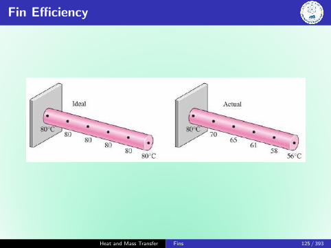
Fin Efficiency
No fin: qconv = hAb(Tb − T∞)
Heat and Mass Transfer Fins 122 / 393

Fin Efficiency
The temperature of the fin will be Tb at the fin base andgradually decrease towards the fin tip.
Convection from the fin surface causes the temperature at anycross-section to drop somewhat from the midsection towardthe outer surfaces.
However, the cross-sectional area of the fins is usually verysmall, and thus the temperature at any cross-section can beconsidered to be uniform.
Also, the fin tip can be assumed for convenience andsimplicity to be adiabatic by using the corrected length for thefin instead of the actual length.
In the limiting case of zero thermal resistance or infinite k, thetemperature of fin will be uniform at the value of Tb. The heattransfer from the fin will be maximum in this case (k →∞):
qfin,max = hAfin(Tb − T∞)
Heat and Mass Transfer Fins 123 / 393

Fin Efficiency
In reality, however, the temperature of the fin will drop along thefin and thus the heat transfer from the fin will be less because ofthe decreasing [T (x)− T∞] toward the fin tip.
To account for the effect of this decrease in temperature on heattransfer, we define fin efficiency as:
ηfin =qfin
qfin,max=
Actual heat transfer rate from the finIdeal heat transfer rate from the fin
if the entire fin were at base temperature
Heat and Mass Transfer Fins 124 / 393
Fin Efficiency
Heat and Mass Transfer Fins 125 / 393

Fin Efficiency: Uniform Cross-Sectional Area
Case A: Infinitely long fins
ηlong fin =qfin
qfin,max=
1
mL
∵ Afin = pLCase B: Adiabatic tip
ηadiabatic =qfin
qfin,max=
tanhmL
mL
Case C: Convection at tip
ηh at tip =qfin
qfin,max=
tanhmLcmLc
Heat and Mass Transfer Fins 126 / 393

Fin Efficiency: Proper Length of a Fin
An important consideration in the design of finned surace isthe selection of the proper fin length, L.
Normally the longer the fin, the larger the heat transfer andthus the higher the rate of heat transfer from the fin.
But also the larger the fin, the bigger the mass, the higher theprice, and the larger the fluid friction.
Therefore, increasing the length of the fin beyond a certainvalue cannot be justified unless the added benefits outweighthe added cost.
Also, ηfin decreases with increasing fin length because of thedecrease in fin temperature with length.
Fin lengths that cause the fin efficiency to drop below 60%usually cannot be justified economically and should beavoided.
η of most fins used in practice is > 90%.
Heat and Mass Transfer Fins 127 / 393

η of Rectangular, Triangular, Parabolic Profiles
Heat and Mass Transfer Fins 128 / 393

η of Annular fins of constant thickness, t
Heat and Mass Transfer Fins 129 / 393

Fin Effectiveness
The performance of the fins is judged on the basis of enhancementof heat transfer relative to the no fin case.
εfin =qfinqno fin
=qf
hAb(Tb − T∞)
where Ab is the fin cross-sectional area at the base.
Heat and Mass Transfer Fins 130 / 393

Fin Effectiveness: Physical Significance
εfin = 1 indicates that the addition of fins to the surfacedoes not affect heat transfer at all. That is, heat conductedto the fin through the base area Ab is equal to the heattransferred from the same area Ab to the surrounding medium.
εfin < 1 indicates that the fin actually acts as insulation,slowing down the heat transfer from the surface. Thissituation can occur when fins made of low k are used.
εfin > 1 indicates that the fins are enhancing heat transferfrom the surface. However, the use of fins cannot be justifiedunless εfin is sufficiently larger than 1 (≥ 2). Finned surfacesare designed on the basis of maximizing effectiveness of aspecified cost or minimizing cost for a desired effectiveness.
Heat and Mass Transfer Fins 131 / 393
Efficiency and Effectiveness
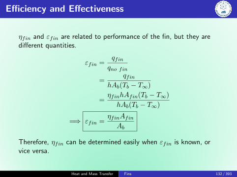
ηfin and εfin are related to performance of the fin, but they aredifferent quantities.
εfin =qfinqno fin
=qfin
hAb(Tb − T∞)
=ηfinhAfin(Tb − T∞)
hAb(Tb − T∞)
=⇒ εfin =ηfinAfinAb
Therefore, ηfin can be determined easily when εfin is known, orvice versa.
Heat and Mass Transfer Fins 132 / 393

ε for a Long Uniform Cross-Section Fin
εfin =qfinqno fin
=
√hPkAcθb
hAb(Tb − T∞)=
√kP
hAc
∵ Ac = Ab and θb = Tb − T∞
k of fin should be high. Ex: Cu, Al, Fe. Aluminium is lowcost, weight, and resistant to corrosion.
P/Ac should be high. Thin plates or slender pin fins
h should be low. Gas instead of liquid; Natural convectioninstead of forced convection. Therefore, in liquid-to-gas heatexchangers (car radiators), fins are placed on the gas side.
Heat and Mass Transfer Fins 133 / 393

Multiple Fins
Heat transfer rate for a surfacecontaining n fins:
qtot,fin = qunfin + qfin
= hAunfin(Tb − T∞)
+ ηfinAfin(Tb − T∞)
qtot,fin = h(Aunfin + ηfinAfin)(Tb − T∞)
Heat and Mass Transfer Fins 134 / 393

Overall Effectiveness
We can also define an overall effectiveness for a finned surface asthe ratio of the total q from the finned surface to the q from thesame surface if there were no fins:
εfin,overall =qfinqnofin
=h(Aunfin + ηfinAfin)(Tb − T∞)
hAnofin(Tb − T∞)
Anofin is the area of the surface when there are no finsAfin is the total surface area of all the fins on the surfaceAunfin is the area of the unfinned portion of the surface.
εfin,overall depends on number of fins per unit length as well asεfin of individual fins.εfin,overall is a better measure of the performance than εfin ofindividual fins.
Heat and Mass Transfer Fins 135 / 393

Problem
Steam in a heating system flows through tubes: outer diameter isD1 = 3 cm and whose walls are maintained at 125◦C. Circularaluminium fins (k = 180 W/m K) of D2 = 6 cm, t = 2 mm areattached. The space between the fins is 3 mm, and thus there are200 fins per meter length of the tube. Surrounded air: T∞ = 27◦C,h = 60 W/m2 K. Determine the increase in heat transfer from thetube per meter of its length as a result of adding fins.
Heat and Mass Transfer Fins 136 / 393

Solution
Known
Properties of the fin, ambient conditions, heat transfer coefficient,dimensions of the fin.
Find
Increase in heat transfer from the tube per meter of its length as aresult of adding fins.
Assumptions
Steady state conditions, 1-D along the rod
Constant properties and uniform h
Negligible radiation exchange with surroundings
Heat and Mass Transfer Fins 137 / 393

Solution: Analysis
In case of no fins (per unit length, l = 1 m:
Anofin = πD1l = 0.0942 m2
qnofin = hAnofin(Tb − T∞) = 554 W
r1 = D1/2 = 0.015 m
r2 = D2/2 = 0.03 m
r2 + t2
r1= 2.07
L = r2 − r1 = 0.015 m
ξ =
(L+
t
2
)√h
kt= 0.207
=⇒ ηfin = 0.95
Heat and Mass Transfer Fins 138 / 393

Solution: Analysis
q from finned portion
Afin = 2π(r2
2 − r21
)+ 2πr2t
= 0.00462 m2
qfin = ηfinqfin,max
= ηfinhAfin(Tb − T∞)
= 27.81 W
q from unfinned portion of tube
Aunfin = 2πr1S
= 0.000283 m3
qunfin = hAunfin(Tb − T∞)
= 1.67 W
There are 200 fins per meter length of the tube. The total heattransfer from the finned tube:
qtot,fin = n(qfin + qunfin) = 5896 W
∴ the increase in heat transfer from the tube per meter of itslength as a result of the addition of fins is:
qincrease = qtot,fin − qnofin = 5342 W per meter tube length
Heat and Mass Transfer Fins 139 / 393

Solution: Comments
Effectiveness
The overall effectiveness of the finned tube is:
εfin,overall =qtot,finqtot,nofin
= 10.6
That is, the rate of heat transfer from the steam tube increases bya factor of 10 as a result of adding fins.
Heat and Mass Transfer Fins 140 / 393
Heat and Mass Transfer
Transient Heat Conduction
Sudheer Siddapuredddy
Department of Mechanical EngineeringIndian Institution of Technology Patna
Heat and Mass Transfer Transient Conduction 141 / 393

Transient Heat Conduction
Time dependent conduction - Temperature history inside aconducting body that is immersed suddenly in a bath of fluid at adifferent temperature.
Ex: Quenching of special alloys, heat treatment of bearings
The temperature of such a body varies with time as well asposition.
T (x, y, z, t)
Heat and Mass Transfer Transient Conduction 142 / 393

Transient Heat Conduction
A body is exposed to ambient
∂2T
∂x2+q
k=
1
α
∂T
∂t
No heat generation
∂T
∂t= α
∂2T
∂x2
α→ Thermal diffusivity (m2/s)
It appears only in the transientconduction
T = f(x, t)
Tt=0 = Ti
∂T
∂x
∣∣∣∣x=0
= 0
qx=±L = h(T∞ − T )
Heat and Mass Transfer Transient Conduction 143 / 393

Lumped Capacitance Model
Lumped: Temperature is essentially uniform throughout the body.
T (x, y, z, t) = T (t)
Copper ball with uniform temperature Potato taken from boiling water
Heat and Mass Transfer Transient Conduction 144 / 393

Lumped Capacitance Model
Hot forging that is initially at uniform temperature, Ti and isquenched by immersing it in a liquid of lower temperature T∞ < Ti
Ein − Eout + Egen = Est
Heat and Mass Transfer Transient Conduction 145 / 393

Lumped Capacitance Model
−hA(T − T∞) = ρV CpdT
dt
T∫T=Ti
dT
T − T∞= − hA
ρV Cp
t∫t=0
dt
θ
θi=T − T∞Ti − T∞
= e−tτ τ =
ρV CphA
τ =
(1
hA
)(ρV Cp) = RtCt
Rt - Resistance to convection heat transferCt - Lumped thermal capacitance of the solid
Heat and Mass Transfer Transient Conduction 146 / 393

Time Constant
θ
θi
∣∣∣∣t=τ
= 0.368
Heat and Mass Transfer Transient Conduction 147 / 393

Total Energy Transfer
The rate of convection heat transfer between the body and itsenvironment at any time: q = hA[T (t)− T∞]Total energy transfer occurring up to sometime, t:
Q =
t∫t=0
qdt
=
t∫t=0
hA[T (t)− T∞]dt
= hA(Ti − T∞)
t∫t=0
e−tτ
Q = ρV Cp(Ti − T∞)[1− e−
tτ
]Heat and Mass Transfer Transient Conduction 148 / 393

Criteria of the Lumped System Analysis
Consider a body exposed toambient
qconv = qcond
h(Ts,2 − T∞) = kTs,1 − Ts,2
Lc
Ts,1 − Ts,2Ts,2 − T∞
=hLck
= Bi
Lc = VA
Heat and Mass Transfer Transient Conduction 149 / 393

Biot Number
Bi =hLck
=h∆T
k∆T/Lc
=Conv. at the surface of the body
Conduction within the body
Bi =Lc/k
1/h
=Conduction resistance within the body
Conv. resistance at the surface
Generally accepted, Bi ≤ 0.1 for assuming lumped.
Heat and Mass Transfer Transient Conduction 150 / 393

Biot Number
Heat and Mass Transfer Transient Conduction 151 / 393
Biot Number
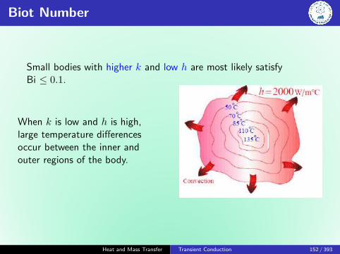
Small bodies with higher k and low h are most likely satisfyBi ≤ 0.1.
When k is low and h is high,large temperature differencesoccur between the inner andouter regions of the body.
Heat and Mass Transfer Transient Conduction 152 / 393

Professor Jean-Baptiste Biot
French physicist, astronomer, andmathematician born in Paris, France.
Professor of mathematical physics atCollege de France .
At the age of 29, he worked on theanalysis of heat conduction evenearlier than Fourier did (unsuccessful).After 7 years, Fourier read Biot’s work.
Awarded the Rumford Medal of theRoyal Society in 1840 for hiscontribution in the field of Polarizationof light.
Heat and Mass Transfer Transient Conduction 153 / 393

Problem: Thermocouple Diameter
Determine the thermocouple junction diameter needed to have atime constant of one second.Ambient: T∞ = 200◦C, h = 400 W/m2 KMaterialproperties: k = 20 W/m K, Cp = 400 J/kg K, ρ = 8500 kg/m3Ans:
0.706 mm
Heat and Mass Transfer Transient Conduction 154 / 393

Problem: Solution
Known
Thermo-physical properties of the thermocouple junction used tomeasure the temperature of a gas stream.Thermal environmental conditions.
Find
Junction diameter needed for a time constant of 1 second.
Assumptions
Temperature of the junction is uniform at any instant.
Radiation exchange with the surroundings is negligible.
Losses by conduction through the leads is negligible.
Constant properties.
Heat and Mass Transfer Transient Conduction 155 / 393
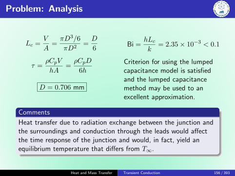
Problem: Analysis
Lc =V
A=πD3/6
πD2=D
6
τ =ρCpV
hA=ρCpD
6h
D = 0.706 mm
Bi =hLck
= 2.35× 10⁻³ < 0.1
Criterion for using the lumpedcapacitance model is satisfiedand the lumped capacitancemethod may be used to anexcellent approximation.
Comments
Heat transfer due to radiation exchange between the junction andthe surroundings and conduction through the leads would affectthe time response of the junction and would, in fact, yield anequilibrium temperature that differs from T∞.
Heat and Mass Transfer Transient Conduction 156 / 393

Problem: Predict the Time of Death
A person is found dead at 5 PM in a room. The temperature ofthe body is measured to be 25◦C when found. Estimate the timeof death of that person.
Known
T of the person at 5 PM.Thermal environmentalconditions.
Find
The time of death of the personis to be estimated.
Heat and Mass Transfer Transient Conduction 157 / 393

Problem: Solution
Assumptions
The body can be modeled as a cylinder.
Radiation exchange with the surroundings is negligible.
The initial temperature of the person is 37◦C.
Assuming properties of water.
Lc =V
A=
(πD2/4)L
πDL+ 2(πD2/4)= 0.069 m
Heat and Mass Transfer Transient Conduction 158 / 393

Problem: Solution
Bi =hLck
= 0.9 > 0.1
Comment: Criterion for using the lumped capacitance model isnot satisfied. However, let us get a rough estimate.
τ =ρCpV
hA=ρCpV
hA= 35891 s
T − T∞Ti − T∞
=25− 20
37− 20= e−
tτ
t = 43923 s = 12.2 hours
Therefore, the person would have died around 5 AM.
Heat and Mass Transfer Transient Conduction 159 / 393

Transient Conduction with Spatial Effects - 1D
A large plane wall A long cylinder A sphere
∂2T
∂x2=
1
α
∂T
∂t
T (x, 0) = Ti Initial
∂T
∂x
∣∣∣∣x=0
= 0 Symmetry
−k ∂T∂x
∣∣∣∣x=L
= h [T (L, t)− T∞] Boundary
Heat and Mass Transfer Transient Conduction 160 / 393

Transient Conduction with Spatial Effects - 1D
In all these three cases posses geometric and thermal symmetry:
the plane wall is symmetric about its center plane (x = 0),
the cylinder is symmetric about its center line(r = 0), and
the sphere is symmetric about its center point (r = 0)
Neglect qrad or incorporate as hr.
The solution, however, involves infinite series, which areinconvenient and time consuming to evaluate.
Heat and Mass Transfer Transient Conduction 161 / 393

Transient Temperature Profiles
Heat and Mass Transfer Transient Conduction 162 / 393
Reduction of Parameters
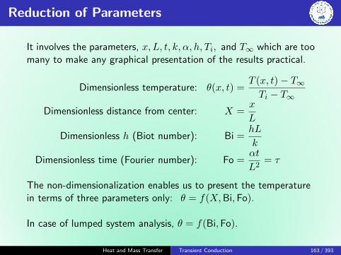
It involves the parameters, x, L, t, k, α, h, Ti, and T∞ which are toomany to make any graphical presentation of the results practical.
Dimensionless temperature: θ(x, t) =T (x, t)− T∞Ti − T∞
Dimensionless distance from center: X =x
L
Dimensionless h (Biot number): Bi =hL
k
Dimensionless time (Fourier number): Fo =αt
L2= τ
The non-dimensionalization enables us to present the temperaturein terms of three parameters only: θ = f(X,Bi,Fo).
In case of lumped system analysis, θ = f(Bi,Fo).
Heat and Mass Transfer Transient Conduction 163 / 393

Fourier Number: Physical Significance
Fo =αt
L2=
(kL2 ∆T
L
)(ρL3Cp
∆Tt
)=
Rate of heat conducted across L of a body of volume L3
Rate of heat stored in a body of volume L3
Fo =QconductedQstored
Heat and Mass Transfer Transient Conduction 164 / 393
Exact Solution: One-Term Approximation
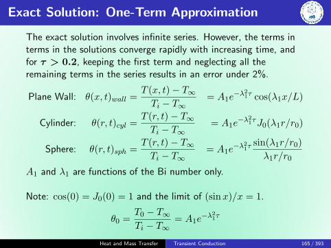
The exact solution involves infinite series. However, the terms interms in the solutions converge rapidly with increasing time, andfor τ > 0.2, keeping the first term and neglecting all theremaining terms in the series results in an error under 2%.
Plane Wall: θ(x, t)wall =T (x, t)− T∞Ti − T∞
= A1e−λ21τ cos(λ1x/L)
Cylinder: θ(r, t)cyl =T (r, t)− T∞Ti − T∞
= A1e−λ21τJ0(λ1r/r0)
Sphere: θ(r, t)sph =T (r, t)− T∞Ti − T∞
= A1e−λ21τ sin(λ1r/r0)
λ1r/r0
A1 and λ1 are functions of the Bi number only.
Note: cos(0) = J0(0) = 1 and the limit of (sinx)/x = 1.
θ0 =T0 − T∞Ti − T∞
= A1e−λ21τ
Heat and Mass Transfer Transient Conduction 165 / 393

Exact Solution: One Term Approximation
Heat and Mass Transfer Transient Conduction 166 / 393

Special Case
1
Bi=
k
hL= 0 corresponds to h→∞,
which corresponds to specified surface temperature, T∞, case.
Heat and Mass Transfer Transient Conduction 167 / 393

Total Energy Transferred from the Wall
The maximum amount of heat that a body can gain (or lose ifTi > T∞) is the change in the energy content of the body:
Qmax = mCp(T∞ − Ti) = ρV Cp(T∞ − Ti)
Qmax represents the amount of heat transfer for t→∞. Theamount of heat transfer, Q at a finite time t is obviously less thanthis. It can be expressed as the sum of the internal energy changesthroughout the entire geometry as:
Q =
∫VρCp[T (x, t)− Ti]dV
Assuming constant properties:
Q
Qmax=
∫V ρCp[T (x, t)− Ti]dVρV Cp(T∞ − Ti)
=1
V
∫V
(1− θ)dV
Heat and Mass Transfer Transient Conduction 168 / 393

Total Energy: One Term Approximation
Plane Wall:
(Q
Qmax
)wall
= 1− θ0,wallsinλ1
λ1
Cylinder:
(Q
Qmax
)cyl
= 1− θ0,cylJ1(λ1)
λ1
Sphere:
(Q
Qmax
)sph
= 1− θ0,wallsinλ1 − λ1 cosλ1
λ1
Heat and Mass Transfer Transient Conduction 169 / 393

Fraction of Total Heat Transfer: Grober Chart
Heat and Mass Transfer Transient Conduction 170 / 393

Graphical Solution: Heisler Charts
Valid for τ > 0.2Plane wall
Heat and Mass Transfer Transient Conduction 171 / 393

Graphical Solution: Heisler Charts
Heat and Mass Transfer Transient Conduction 172 / 393
Limitations
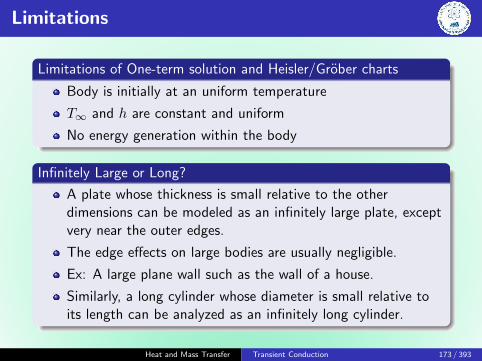
Limitations of One-term solution and Heisler/Grober charts
Body is initially at an uniform temperature
T∞ and h are constant and uniform
No energy generation within the body
Infinitely Large or Long?
A plate whose thickness is small relative to the otherdimensions can be modeled as an infinitely large plate, exceptvery near the outer edges.
The edge effects on large bodies are usually negligible.
Ex: A large plane wall such as the wall of a house.
Similarly, a long cylinder whose diameter is small relative toits length can be analyzed as an infinitely long cylinder.
Heat and Mass Transfer Transient Conduction 173 / 393

Problem
An ordinary egg can be approximated as a 5 cm diameter sphere.The egg is initially at a uniform temperature of 5◦C and is droppedinto boiling water at 95◦C. Taking the convection heat transfercoefficient to be h = 1200 W/m2 K, determine how long it willtake for the center of the egg to reach 70◦C.
The water content of eggs is about74%, and thus k and α of eggs can beapproximated by those of water at theaverage temperature(5 + 70)/2 = 37.5◦C.
k = 0.627 W/m K; α = k/ρcp = 0.151× 10⁻⁶ m2/s
Heat and Mass Transfer Transient Conduction 174 / 393

Solution
Ti = 5◦C; T∞ = 95◦C T0 = 70◦C h = 1200 W/m2 K
k = 0.627 W/m K; α = k/ρcp = 0.151× 10⁻⁶ m2/s
BiLc =hLck
= 16 Bir0 =hr0
k= 47.8
One-term approximation
θ0 =T0 − T∞Ti − T∞
= A1e−λ21τ , τ > 0.2
τ = αtr20
λ1 = 3.0754; A1 = 1.9958
τ = 0.209, Ans: 14.4 min
Heat and Mass Transfer Transient Conduction 175 / 393
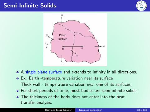
Semi-Infinite Solids
A single plane surface and extends to infinity in all directions.
Ex: Earth -temperature variation near its surface
Thick wall - temperature variation near one of its surfaces
For short periods of time, most bodies are semi-infinite solids.
The thickness of the body does not enter into the heattransfer analysis.
Heat and Mass Transfer Transient Conduction 176 / 393

Semi-Infinite Solids
∂2T
∂x2=
1
α
∂T
∂t
T (0, t) = Ts; T (x→∞, t) = Ti
T (x, 0) = Ti
Convert PDE into ODE by combining the two independentvariables x and t into a single variable η:
η =x√4αt
Similarity variable, η
η = 0 at x = 0
η →∞ at x→∞η →∞ at t = 0
Heat and Mass Transfer Transient Conduction 177 / 393

Semi-Infinite Solids
∂T
∂t=dT
dη
dη
dt= − x
2t√
4αt
dT
dη
∂T
∂x=dT
dη
dη
dx=
1√4αt
dT
dη
∂2T
∂x2=
d
dη
(∂T
∂x
)dη
dx=
1
4αt
d2T
dη2
Heat and Mass Transfer Transient Conduction 178 / 393

Convective Boundary Condition
The exact solution for a convective boundary condition:
Temperature distribution
1− θ =T (x, t)− TsT∞ − Ts
= efrc
(x
2√αt
)− exp
(hx
k+h2αt
k2
)efrc
(x
2√αt
+h√αt
k
)The complementary error function, erfc ξ is defined aserfc ξ = 1− erf ξ. The Gaussian error function, erf ξ, is a standardmathematical function that is tabulated.
Heat and Mass Transfer Transient Conduction 179 / 393

Heat and Mass Transfer
Multidimensional Steady-State Conduction
Sudheer Siddapuredddy
Department of Mechanical EngineeringIndian Institution of Technology Patna
Heat and Mass Transfer Multidimensional Conduction 180 / 393

Two-Dimensional, Steady-State Conduction
Governing equation
∂2T
∂x2+∂2T
∂y2= 0
Solve for T (x, y)
Determine q′′x and q′′y from the rate equations
Methodologies/Approaches
Analytical
Graphical
Numerical
Heat and Mass Transfer Multidimensional Conduction 181 / 393

Analytical Approach
Method of separation of variables:
θ(x, y) =2
π
∞∑n=1
(−1)n+1 + 1
nsin
nπx
L
sinh(nπy/L)
sinh(nπW/l)
Heat and Mass Transfer Multidimensional Conduction 182 / 393

Graphical Approach
Conduction Shape Factor
q = kS∆T1−2
where ∆T1−2 is the temp. difference between boundaries.
S (m) depends on the geometry of the system only and R = 1/Sk.
Heat and Mass Transfer Multidimensional Conduction 183 / 393

Conduction Shape Factor
Heat and Mass Transfer Multidimensional Conduction 184 / 393

Conduction Shape Factor
Heat and Mass Transfer Multidimensional Conduction 185 / 393

Conduction Shape Factor
Heat and Mass Transfer Multidimensional Conduction 186 / 393

Conduction Shape Factor
Heat and Mass Transfer Multidimensional Conduction 187 / 393

Numerical Approach
(a) Nodal Network (b) Finite-difference approximation
Heat and Mass Transfer Multidimensional Conduction 188 / 393

Heat and Mass Transfer
Numerical Methods - FDS
Sudheer Siddapuredddy
Department of Mechanical EngineeringIndian Institution of Technology Patna
Heat and Mass Transfer Numerical Methods - FDS 189 / 393

Numerical Technique
Advances in numerical computing now allow for complex heattransfer problems to be solved rapidly on computers. Someexamples are:
Finite-difference method
Finite-element method
Boundary-element method
In general, these techniques are routinely used to solve problems inheat transfer, fluid dynamics, stress analysis, electrostatics andmagnetics, etc. Finite-difference method is ease of application.
Numerical techniques result in an approximate solution.
Properties (e.g.,T , u) are determined at discrete points in theregion of interest - referred as nodal points or nodes.
Heat and Mass Transfer Numerical Methods - FDS 190 / 393

Finite-Difference Analysis
Heat and Mass Transfer Numerical Methods - FDS 191 / 393

Finite-Difference Analysis
∂2T
∂x2+∂2T
∂y2= 0 (1)
∂2T
∂x2
∣∣∣∣m,n
≈∂T∂x
∣∣m+1/2,n
− ∂T∂x
∣∣m−1/2,n
∆x
≈ Tm+1,n − 2Tm,n + Tm−1,n
(∆x)2(2)
∂2T
∂y2
∣∣∣∣m,n
≈ Tm+1,n − 2Tm,n + Tm−1,n
(∆y)2(3)
Using a network for which ∆x = ∆y and substituting Eqs. (2)and (3) in Eq. (1):
Tm,n+1 + Tm,n−1 + Tm+1,n + Tm−1,n − 4Tm,n = 0
Heat and Mass Transfer Numerical Methods - FDS 192 / 393
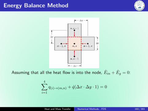
Energy Balance Method
Assuming that all the heat flow is into the node, Ein + Eg = 0:
4∑i=1
q(i)→(m,n) + q(∆x ·∆y · 1) = 0
Heat and Mass Transfer Numerical Methods - FDS 193 / 393
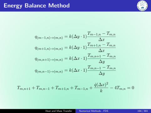
Energy Balance Method
q(m−1,n)→(m,n) = k(∆y · 1)Tm−1,n − Tm,n
∆x
q(m+1,n)→(m,n) = k(∆y · 1)Tm+1,n − Tm,n
∆x
q(m,n+1)→(m,n) = k(∆x · 1)Tm,n+1 − Tm,n
∆y
q(m,n−1)→(m,n) = k(∆x · 1)Tm,n−1 − Tm,n
∆y
Tm,n+1 + Tm,n−1 + Tm+1,n + Tm−1,n +q(∆x)2
k− 4Tm,n = 0
Heat and Mass Transfer Numerical Methods - FDS 194 / 393

Energy Balance Method
q(m−1,n)→(m,n) = k(∆y · 1)Tm−1,n − Tm,n
∆x
q(m,n+1)→(m,n) = k(∆x · 1)Tm,n+1 − Tm,n
∆y
q(m+1,n)→(m,n) = k(∆y
2· 1)
Tm+1,n − Tm,n∆x
q(m,n−1)→(m,n) = k(∆x
2· 1)
Tm,n−1 − Tm,n∆y
q(∞)→(m,,n) = h
(∆x
2· 1)
(T∞−Tm,n)+h
(∆y
2· 1)
(T∞−Tm,n)
Tm,n+1+Tm,n−1+1
2(Tm+1,n+Tm−1,n)+
h∆x
kT∞−
(3 +
h∆x
k
)Tm,n = 0
Heat and Mass Transfer Numerical Methods - FDS 195 / 393

Specified Heat Flux Boundary Condition
qsurface + kAT1 − T0
δx+ qA
∆x
2= 0
Heat and Mass Transfer Numerical Methods - FDS 196 / 393

Problem
Consider a large uranium plate of thickness L = 4 cm andk = 28 W/m K in which heat is generated uniformly at a constantrate of q = 5× 10⁶ W/m3. One side of the plate is maintained at0◦C by iced water while the other side is subjected to convectionto an environment at T∞ = 30◦C with h = 45 W/m2 K.Considering a total of three equally spaced nodes in the medium,two at the boundaries and one at the middle, estimate the exposedsurface temperature of the plate under steady conditions using thefinite difference approach.
Heat and Mass Transfer Numerical Methods - FDS 197 / 393

Solution
For the interior node (1), the energy balance would result in:
T0 − 2T1 + T2
(∆x)2+q
k= 0
T0 − 2T1 + T2 = − q(∆x)2
k
2T1 − T2 = 71.43 (1)
Let us write the governing equation for the corner Node (2):
h(T∞ − T2) + kAT1 − T2
∆x+ qA
∆x
2= 0
T1 − (1 +h∆x
k)T2 = −h∆x
kT∞ −
q(∆x)2
2k
T1 − 1.032T2 = −36.68 (2)
Heat and Mass Transfer Numerical Methods - FDS 198 / 393

Solution: Generalizing
T0 − 2T1 + T2 = − q(∆x)2
k
Tm−1 − 2Tm + Tm+1 = − q(∆x)2
k
T1 − (1 +h∆x
k)T2 = −h∆x
kT∞ −
q(∆x)2
2k
TM−1 − (1 +h∆x
k)TM = −h∆x
kT∞ −
q(∆x)2
2k
Heat and Mass Transfer Numerical Methods - FDS 199 / 393

Problem
Consider an aluminum alloy fin (k = 180 W/m K) of triangularcross section with length L = 5 cm, base thickness b = 1 cm, andvery large width w in the direction normal to the plane of paper.The base of the fin is maintained at a temperature of T0 = 200◦C.The fin is losing heat to the surrounding medium at T∞ = 25◦Cwith a heat transfer coefficient of h = 15 W/m2 K. Using the finitedifference method with six equally spaced nodes along the fin inthe x-direction, determine (a) the temperatures at the nodes, (b)the rate of heat transfer from the fin for w = 1 m, and (c) the finefficiency.
Heat and Mass Transfer Numerical Methods - FDS 200 / 393

Problem
T0 = 200◦C k = 180 W/m K
b = 1 cm w = 1 cm
T∞ = 25◦C h = 15 W/m2 K
Heat and Mass Transfer Numerical Methods - FDS 201 / 393

Solution
qleft + qright + qconv = 0
kAleftTm−1 − Tm
∆x+ kAright
Tm+1 − Tm∆x
+ hAconv(T∞ − Tm) = 0
Aleft = 2w[L− (m− 1/2)∆x] tan θ
Aright = 2w[L− (m+ 1/2)∆x] tan θ
Aconv = 2w(∆x/ cos θ)
tan θ =b/2
L= 0.1 =⇒ θ = 5.71◦
Heat and Mass Transfer Numerical Methods - FDS 202 / 393

Solution
(5.5−m)Tm−1 − (10.01− 2m)Tm + (4.5−m)Tm+1 = −0.209
Four equations for m = 1→ 4. Boundary condition at node (5):
kAleftT4 − T5
∆x+ hAconv(T∞ − T5)
Aleft = 2w(∆x/2) tan θ Aconv = 2w∆x/2
cos θ
Total 5 equations with 5 unknowns.
Heat and Mass Transfer Numerical Methods - FDS 203 / 393

Solution
T1
T2
T3
T4
T5
=
−8.01 3.5 0 0 0
3.5 −6.01 2.5 0 00 2.5 −4.01 1.5 00 0 1.5 −2.01 0.50 0 0 1 −1.01
−1
×
−900.21−0.21−0.21−2.1−0.21
=
198.6197.1195.7194.3192.9
◦C
Heat and Mass Transfer Numerical Methods - FDS 204 / 393

Direct/Iterative Methods
Direct Methods
Solve in a systematic manner following a series of well-definedsteps.
Iterative Methods
Start with an initial guess for the solution, and iterate untilsolution converges.
Heat and Mass Transfer Numerical Methods - FDS 205 / 393

Gauss-Seidel/Iterative Method
Application of the Gauss-Seidel iterative method to the finitedifference equations in the previous triangular fin example.
Heat and Mass Transfer Numerical Methods - FDS 206 / 393

Transient: The Explicit Method
1
α
∂T
∂t=∂2T
∂x2+∂2T
∂y2
The problem must be discretized in time.
t = p∆t
∂T
∂t
∣∣∣∣m,n
≈ T p+1m,n − T pm,n
∆t
In explicit method of solution, the temperatures are evaluated atthe previous (p) time - forward-difference approximation to thetime derivative.
1
α
T p+1m,n − T pm,n
∆t=T pm+1,n + T pm−1,n − 2T pm,n
(∆x)2
+T pm,n+1 + T pm,n−1 − 2T pm,n
(∆y)2
Heat and Mass Transfer Numerical Methods - FDS 207 / 393
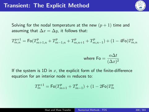
Transient: The Explicit Method
Solving for the nodal temperature at the new (p+ 1) time andassuming that ∆x = ∆y, it follows that:
T p+1m,n = Fo(T pm+1,n + T pm−1,n + T pm,n+1 + T pm,n−1) + (1− 4Fo)T pm,n
where Fo =α∆t
(∆x)2
If the system is 1D in x, the explicit form of the finite-differenceequation for an interior node m reduces to:
T p+1m = Fo(T pm+1 + T pm−1) + (1− 2Fo)T pm
Heat and Mass Transfer Numerical Methods - FDS 208 / 393

Stability Criterion
Explicit method is not unconditionally stable.
The solution may be characterized by numerically inducedoscillations, which are physically impossible
Oscillations may become unstable, causing the solution todiverge from the actual steady-state conditions.
Stability Criterion
The criterion is determined by requiring that the coefficientassociated with the node of interest at the previous time is greaterthan or equal to zero.
T p+1m = Fo(T pm+1 + T pm−1) + (1− 2Fo)T pm
1D :(1− 2Fo) ≥ 0 =⇒ Fo ≤ 1
2
2D :(1− 4Fo) ≥ 0 =⇒ Fo ≤ 1
4
Heat and Mass Transfer Numerical Methods - FDS 209 / 393

Energy Balance at the Boundary
Ein + Eg = Est
hA(T∞ − T p0 ) +kA
∆x(T p1 − T
p0 ) = ρA
∆x
2CpT p+1
0 − T p0∆t
T p+10 = 2 Fo (T p1 + Bi T∞) + (1− 2 Fo− 2 Bi Fo)T p0
Bi = h∆xk
From the stability Criteria:
1− 2 Fo− 2 Bi Fo ≥ 0
Fo(1 + Bi) ≤ 1
2
Heat and Mass Transfer Numerical Methods - FDS 210 / 393

Problem
A fuel element of a nuclear reactor is in the shape of a plane wallof thickness 2L = 20 mm and is convectively cooled at bothsurfaces, with h = 1100 W/m2 K and T∞ = 250◦C. At normaloperating power, heat is generated uniformly within the element ata volumetric rate of q1 = 107 W/m3. A departure from thesteady-state conditions associated with normal operation will occurif there is a change in the generation rate. Consider a suddenchange to q2 = 2× 10⁷ W/m3, and determine the fuel elementtemperature distribution after 1.5 s.
The fuel elementthermal properties arek = 30 W/m K andα = 5× 10⁻⁶ m2/s.
Heat and Mass Transfer Numerical Methods - FDS 211 / 393
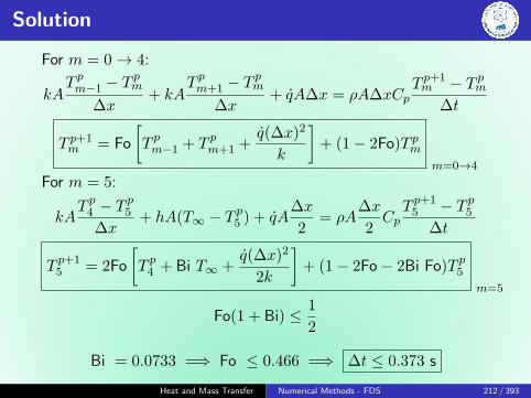
Solution
For m = 0→ 4:
kAT pm−1 − T
pm
∆x+ kA
T pm+1 − Tpm
∆x+ qA∆x = ρA∆xCp
T p+1m − T pm
∆t
T p+1m = Fo
[T pm−1 + T pm+1 +
q(∆x)2
k
]+ (1− 2Fo)T pm
m=0→4
For m = 5:
kAT p4 − T
p5
∆x+ hA(T∞ − T p5 ) + qA
∆x
2= ρA
∆x
2CpT p+1
5 − T p5∆t
T p+15 = 2Fo
[T p4 + Bi T∞ +
q(∆x)2
2k
]+ (1− 2Fo− 2Bi Fo)T p5
m=5
Fo(1 + Bi) ≤ 1
2
Bi = 0.0733 =⇒ Fo ≤ 0.466 =⇒ ∆t ≤ 0.373 s
Heat and Mass Transfer Numerical Methods - FDS 212 / 393

Solution
Assuming ∆t = 0.3 s, Fo = 0.375,
T p+10 = 0.375(2T p1 + 2.67) + 0.250T p0
T p+11 = 0.375(T p0 + T p2 + 2.67) + 0.250T p0
T p+12 = 0.375(T p1 + T p3 + 2.67) + 0.250T p0
T p+13 = 0.375(T p2 + T p4 + 2.67) + 0.250T p0
T p+14 = 0.375(T p3 + T p5 + 2.67) + 0.250T p0
T p+15 = 0.750(T p4 + 19.67) + 0.195T p0
For 1D, steady state, q, symmetrical about the plane:
T (x) =qL2
2k
(1− x2
L2
)+ Ts
Ts = T∞ +qL
h
T p=05 = 250+
107 × 0.01
1100= 340.9◦C
T p=0m = 16.67(1−10000x2)+340.9
Heat and Mass Transfer Numerical Methods - FDS 213 / 393

Solution
Heat and Mass Transfer Numerical Methods - FDS 214 / 393

Transient: The Implicit Method
1
α
∂T
∂t=∂2T
∂x2+∂2T
∂y2
∂T
∂t
∣∣∣∣m,n
≈ T p+1m,n − T pm,n
∆t
In implicit method of solution, the temperatures are evaluated atthe new (p+ 1) time - backward-difference approximation to thetime derivative.
1
α
T p+1m,n − T pm,n
∆t=T p+1m+1,n + T p+1
m−1,n − 2T p+1m,n
(∆x)2
+T p+1m,n+1 + T p+1
m,n−1 − 2T p+1m,n
(∆y)2
Heat and Mass Transfer Numerical Methods - FDS 215 / 393

Problem
A fuel element of a nuclear reactor is in the shape of a plane wallof thickness 2L = 20 mm and is convectively cooled at bothsurfaces, with h = 1100 W/m2 K and T∞ = 250◦C. At normaloperating power, heat is generated uniformly within the element ata volumetric rate of q1 = 107 W/m3. A departure from thesteady-state conditions associated with normal operation will occurif there is a change in the generation rate. Consider a suddenchange to q2 = 2× 10⁷ W/m3, and determine the fuel elementtemperature distribution after 1.5 s.
The fuel elementthermal properties arek = 30 W/m K andα = 5× 10⁻⁶ m2/s.
Heat and Mass Transfer Numerical Methods - FDS 216 / 393

Solution
For m = 0→ 4:
kAT p+1m−1 − T
p+1m
∆x+kA
T p+1m+1 − T
p+1m
∆x+qA∆x = ρA∆xCp
T p+1m − T pm
∆t
Fo T p+1m − (1 + 2Fo)T p+1
m + FoT p+1m+1 = −T pm − Fo
q(∆x)2
k m=0→4
For m = 5:
kAT p+1
4 − T p+15
∆x+hA(T∞−T p+1
5 )+qA∆x
2= ρA
∆x
2CpT p+1
5 − T p5∆t
2FoT p+14 − (1 + 2Fo + 2Bi Fo)T p+1
5 = −T p5 − Foq(∆x)2
k m=5
Heat and Mass Transfer Numerical Methods - FDS 217 / 393

Heat and Mass Transfer
Introduction to Convection
Sudheer Siddapuredddy
Department of Mechanical EngineeringIndian Institution of Technology Patna
Heat and Mass Transfer Introduction to Convection 218 / 393

Convective Heat Transfer
Convective heat transfer involves
fluid motion
heat conduction
The fluid motion enhances the heattransfer, since it brings hotter andcooler chunks of fluid into contact,initiating higher rates of conduction at agreater number of sites in fluid.Therefore, the rate of heat transferthrough a fluid is much higher byconvection than it is by conduction.
Higher the fluid velocity, the higher therate of heat transfer.
Heat and Mass Transfer Introduction to Convection 219 / 393

Convective Heat Transfer
Convection heat transfer strongly depends on
fluid properties: µ, k, ρ, Cp
fluid velocity: V
geometry and the roughness of the solid surface
type of fluid flow (laminar or turbulent)
Newton’s law of cooling
qconv = hAs (Ts − T∞)
T∞ is the temp. of the fluid sufficiently far from the surface
Heat and Mass Transfer Introduction to Convection 220 / 393

Total Heat Transfer Rate
Local heat flux
q′′conv = hl (Ts − T∞)
hl is the local convection coefficient
Flow conditions vary on the surface: q′′, h vary along the surface.
The total heat transfer rate q:
qconv =
∫As
q′′dAs
= (Ts − T∞)
∫As
hdAs
Heat and Mass Transfer Introduction to Convection 221 / 393

Total Heat Transfer Rate
Defining an average convection coefficient h for the entire surface,
qconv = hAs (Ts − T∞)
h =1
As
∫As
hdAs
Heat and Mass Transfer Introduction to Convection 222 / 393

No-Temperature-Jump
A fluid flowing over a stationary surface - no-slip condition
A fluid and a solid surface will have the same T at the point ofcontact, known as no-temperature-jump condition.
Heat and Mass Transfer Introduction to Convection 223 / 393
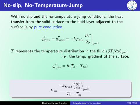
No-slip, No-Temperature-Jump
With no-slip and the no-temperature-jump conditions: the heattransfer from the solid surface to the fluid layer adjacent to thesurface is by pure conduction.
q′′conv = q′′cond = −kfluid∂T
∂y
∣∣∣∣y=0
T represents the temperature distribution in the fluid (∂T/∂y)y=0
i.e., the temp. gradient at the surface.
q′′conv = h(Ts − T∞)
h =−kfluid
(∂T∂y
)y=0
Ts − T∞
Heat and Mass Transfer Introduction to Convection 224 / 393

Problem
Experimental results for the local heat transfer coefficient hx forflow over a flat plate with an extremely rough surface were foundto fit the relation hx(x) = x−0.1 where x (m) is the distance fromthe leading edge of the plate.
Develop an expression for the ration of the average heattransfer coefficient hx for a path of length x to the local heattransfer coefficient hx at x.
Plot the variation of hx and hx as a function of x.
Heat and Mass Transfer Introduction to Convection 225 / 393
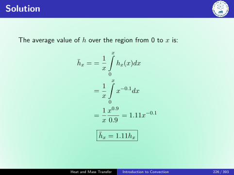
Solution
The average value of h over the region from 0 to x is:
hx = =1
x
x∫0
hx(x)dx
=1
x
x∫0
x−0.1dx
=1
x
x0.9
0.9= 1.11x−0.1
hx = 1.11hx
Heat and Mass Transfer Introduction to Convection 226 / 393

Solution
Comments
Boundary layer development causes both hl and h to decrease withincreasing distance from the leading edge. The average coefficientup to x must therefore exceed the local value at x.
Heat and Mass Transfer Introduction to Convection 227 / 393

Nusselt Number
Nu =hLckfluid
Heat transfer through the fluid layer willbe by convection when the fluid involvessome motion and by conduction whenthe fluid layer is motionless.
qconv = h∆T qcond = k∆T
L
qconvqcond
=h∆T
k∆T/L=hL
k= Nu
Heat and Mass Transfer Introduction to Convection 228 / 393

Nusselt Number
Nu =qconvqcond
Nusselt number: enhancement of heat transfer through a fluidlayer as a result of convection relative to conduction across thesame fluid layer.
Nu >> 1 for a fluid layer - the more effective the convection
Nu = 1 for a fluid layer - heat transfer across the layer is by pureconduction
Nu < 1 ???
Heat and Mass Transfer Introduction to Convection 229 / 393

Prof. Wilhem Nußelt
German engineer, born in Germany (1882)
Doctoral thesis - Conductivity of InsulatingMaterials
Prof. - Heat and Momentum Transfer inTubes
1915 - pioneering work in basic laws oftransfer
Dimensionless groups - similarity theory of heat transfer
Film condensation of steam on vertical surfaces
Combustion of pulverized coal
Analogy of heat transfer and mass transfer in evaporation
Worked till 70 years. Lived for 75 years and died in Munchen onSeptember 1, 1957.
Heat and Mass Transfer Introduction to Convection 230 / 393

External and Internal Flows
External - flow of an unbounded fluid over a surface
Internal - flow is completely bounded by solid surfaces
Heat and Mass Transfer Introduction to Convection 231 / 393

Laminar and Turbulent Flows
Laminar - smooth and orderly: flow of high-viscosity fluids such asoils at low velocitiesInternal - chaotic and highly disordered fluid motion: flow oflow-viscosity fluids such as air at high velocitiesThe flow regime greatly influences the heat transfer rates and therequired power for pumping.
Heat and Mass Transfer Introduction to Convection 232 / 393

Reynolds Number
Osborne Reynolds in 1880’s, discovered that the flow regimedepends mainly on the ratio of the inertia forces to viscous forcesin the fluid.
Re can be viewed as the ratio of the inertia forces to the viscousforces acting on a fluid volume element.
Re =Inertia forces
Viscous=V Lcν
=ρV Lcµ
Heat and Mass Transfer Introduction to Convection 233 / 393

The Effects of Turbulence
Taylor and Von Karman (1937)
Turbulence is an irregular motion which in general makes itsappearance in fluids, gaseous or liquids, when they flow past solidsurfaces or even when neighboring streams of same fluid past overone another.
Turbulent fluid motion is an irregular condition of flow in whichvarious quantities show a random variation with time and spacecoordinates, so that statistically distinct average values can bediscerned.
Heat and Mass Transfer Introduction to Convection 234 / 393
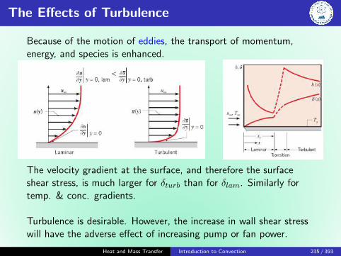
The Effects of Turbulence
Because of the motion of eddies, the transport of momentum,energy, and species is enhanced.
The velocity gradient at the surface, and therefore the surfaceshear stress, is much larger for δturb than for δlam. Similarly fortemp. & conc. gradients.
Turbulence is desirable. However, the increase in wall shear stresswill have the adverse effect of increasing pump or fan power.
Heat and Mass Transfer Introduction to Convection 235 / 393
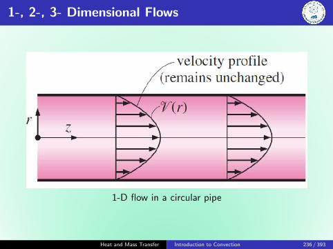
1-, 2-, 3- Dimensional Flows
1-D flow in a circular pipe
Heat and Mass Transfer Introduction to Convection 236 / 393

Velocity Boundary Layer
Vx=δ = 0.99U∞
Heat and Mass Transfer Introduction to Convection 237 / 393

Wall Shear Stress
Friction force per unit area is called sheat stress
Surface shear stress
τw = µ∂u
∂y
∣∣∣∣y=0
The determination of τw is not practical as it requires a knowledgeof the flow velocity profile. A more practical approach in externalflow is to relate τw to the upstream velocity U∞ as:
Skin friction coefficient
τw = CfρU2∞
2
Friction force over the entire surface
Ff = CfAsρU2∞
2
Heat and Mass Transfer Introduction to Convection 238 / 393

Thermal Boundary Layer
δt at any location along the surface at which(T − Ts) = 0.99(T∞ − Ts)
Heat and Mass Transfer Introduction to Convection 239 / 393

Prandtl Number
Shape of the temp. profile in the thermal boundary layerdictates the convection heat transfer between a solid surfaceand the fluid flowing over it.
In flow over a heated (or cooled) surface, both velocity andthermal boundary layers will develop simultaneously.
Noting that the fluid velocity will have a strong influence onthe temp. profile, the development of the velocity boundarylayer relative to the thermal boundary layer will have a strongeffect on the convection heat transfer.
Pr =Molecular diffusivity of momentum
Molecular diffusivity of heat=ν
α=µCpk
Heat and Mass Transfer Introduction to Convection 240 / 393

Prandtl Number
Typical ranges of Pr for common fluids
Fluid Pr
Liquid metals 0.004-0.030Gases 0.7-1.0Water 1.7-13.7Light organic fluids 5-50Oils 50-100,000Glycerin 2000-100,000
Heat and Mass Transfer Introduction to Convection 241 / 393

Prandtl Number
δ
δt≈ Prn
n is positive exponent
Pr ∼= 1 for gases =⇒ both momentum and heat dissipatethrough the fluid at about the same rate.Heat diffuses very quickly in liquid metals (Pr < 1).Heat diffuses very slowly in oils (Pr > 1) relative tomomentum.Therefore, thermal boundary layer is much thicker for liquidmetals and much thinner for oils relative to the velocityboundary layer.
δ = δt for Pr = 1
δ > δt for Pr > 1
δ < δt for Pr < 1
Pr =ν
α
Heat and Mass Transfer Introduction to Convection 242 / 393

Prof. Ludwig Prandtl
German Physicist, born in Bavaria (1875 -1953)
Father of aerodynamics
Prof. of Applied Mechanics at Gottingen for49 years (until his death)
His work in fluid dynamics is still used todayin many areas of aerodynamics and chemicalengineering.
His discovery in 1904 of the Boundary Layer which adjoins thesurface of a body moving in a fluid led to an understanding of skinfriction drag and of the way in which streamlining reduces the dragof airplane wings and other moving bodies.
Heat and Mass Transfer Introduction to Convection 243 / 393

Heat and Mass Transfer
Convection Equations
Sudheer Siddapuredddy
Department of Mechanical EngineeringIndian Institution of Technology Patna
Heat and Mass Transfer Convection Equations 244 / 393

Assumptions
Assuming the flow/fluid to be:
2D, Steady
Newtonian
constant properties (ρ, µ, k, etc.)
Heat and Mass Transfer Convection Equations 245 / 393

Continuity Equation
Rate of mass flow into CV = Rate of mass flow out of CV
rate of fluid entering CVleft:
ρu(dy · 1)
rate of fluid leaving CVright:
ρ(u+∂u
∂xdx)(dy · 1)
ρu(dy · 1) +ρv(dx · 1) = ρ(u+∂u
∂xdx)(dy · 1) +ρ(v+
∂v
∂ydy)(dx · 1)
∂u
∂x+∂v
∂y= 0
Heat and Mass Transfer Convection Equations 246 / 393

Momentum Equation
Expressing Newton’s second law of motion for the control volume:
(Mass) (Acceleration in x) = (Net body and surface forces in x)
δm · ax = Fsurface,x + Fbody,x (3)
δm = ρ(dx · dy · 1)
ax =du
dt=∂u
∂x
dx
dt+∂u
∂y
dy
dt
= u∂u
∂x+ v
∂u
∂y(4)
Steady state doesn’t mean that acceleration is zero.Ex: Garden hose nozzle
Heat and Mass Transfer Convection Equations 247 / 393

Momentum Equation
Body forces: gravity, electric and magnetic forces - ∝ volume.Surface forces: pressure forces due to hydrostatic pressure andshear stresses due to viscous effects - ∝ surface area.
Viscous forces has two components:
1 normal to the surface- normal stressrelated to velocity gradients ∂u/∂x and ∂v/∂y
2 along the wall surface - shear stressrelated to ∂u/∂y
For simplicity, the normal stresses are neglected.
Heat and Mass Transfer Convection Equations 248 / 393

Momentum Equation
Fsurface,x =
(∂τ
∂ydy
)(dx · 1)−
(∂P
∂xdx
)(dy · 1)
=
(∂τ
∂y− ∂P
∂x
)(dx · dy · 1)
τ = µ(∂u∂y
)=
(µ∂2u
∂y2− ∂P
∂x
)(dx · dy · 1) (5)
Heat and Mass Transfer Convection Equations 249 / 393
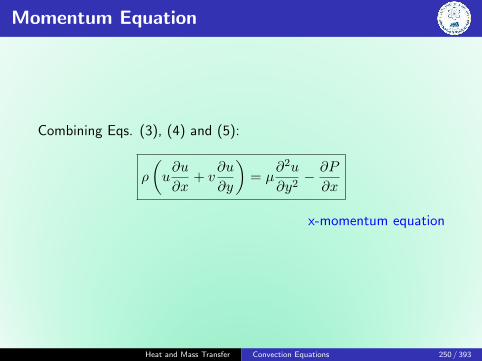
Momentum Equation
Combining Eqs. (3), (4) and (5):
ρ
(u∂u
∂x+ v
∂u
∂y
)= µ
∂2u
∂y2− ∂P
∂x
x-momentum equation
Heat and Mass Transfer Convection Equations 250 / 393

Boundary layer approximations
∂P
∂y= 0
y-momentum equation
P = P (x) =⇒ ∂P
∂x=dP
dx
Heat and Mass Transfer Convection Equations 251 / 393

Energy Equation: Balance
(Ein − Eout)by mass + (Ein − Eout)by heat + (Ein − Eout)by work = 0(6)
Flowing fluid stream: is associated with enthalpy (internal energyand flow energy), potential energy (PE) and kinetic energy (KE)
Heat and Mass Transfer Convection Equations 252 / 393

Energy Balance: by Mass
The total energy of a flowing stream is:
m(h+ pe+ ke) = m
h+��>0
gz +�����>
0u2 + v2
2
= mCpT
KE: [m2/s2] ≈ J/kg. h is in kJ/kg. So, KE is expressed in kJ/kgby dividing it by 1000. KE term at low velocities is negligible.By similar argument, PE term is negligible.
(Ein − Eout)by mass,x = (mCpT )x −[(mCpT )x +
∂(mCpT )x∂x
dx
]= −∂[ρu(dy · 1)CpT ]
∂xdx
(Ein − Eout)by mass = −ρCp(u∂T
∂x+ v
∂T
∂y
)dxdy (7)
Heat and Mass Transfer Convection Equations 253 / 393
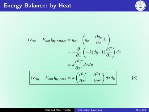
Energy Balance: by Heat
(Ein − Eout)by heat,x = qx −(qx +
∂qx∂x
dx
)= − ∂
∂x
(−k(dy · 1)
∂T
∂x
)dx
= k∂2T
∂x2dxdy
(Ein − Eout)by heat = k
(∂2T
∂x2+∂2T
∂y2
)dxdy (8)
Heat and Mass Transfer Convection Equations 254 / 393

Energy Balance: by Work
Work done by body forces: considered only if significantgravitational, electric, or magnetic effects exist.
Work done by surface faces: consists of forces due to fluidpressure and viscous shear stresses.
Work done by pressure (the flow work) is accounted in enthalpyShear stresses that result from viscous effects are usually small(low velocities)
Heat and Mass Transfer Convection Equations 255 / 393

Energy Equation
Combining Eqs. (6), (7), and (8):
ρCp
(u∂T
∂x+ v
∂T
∂y
)︸ ︷︷ ︸
convection
= k
(∂2T
∂x2+∂2T
∂y2
)︸ ︷︷ ︸
conduction
Net energy convected by the fluid out of CV
=
Net energy transfered into CV by conduction
Heat and Mass Transfer Convection Equations 256 / 393

Energy Equation with Viscous Shear Stresses
When viscous shear stresses are not neglected, then:
ρCp
(u∂T
∂x+ v
∂T
∂y
)︸ ︷︷ ︸
convection
= k
(∂2T
∂x2+∂2T
∂y2
)︸ ︷︷ ︸
conduction
+ µΦ︸︷︷︸viscous dissipation
where the viscous dissipation term is given as:
µΦ = µ
(∂u
∂y+∂v
∂x
)2
+ 2µ
[(∂u
∂x
)2
+
(∂v
∂y
)2]
This accounts for the rate at which mechanical work is irreversiblyconverted to thermal energy due to viscous effects in the fluid.
Heat and Mass Transfer Convection Equations 257 / 393

Energy Equation with no Convection
u∂T
∂x+ v
∂T
∂y︸ ︷︷ ︸advection
= α
(∂2T
∂x2+∂2T
∂y2
)︸ ︷︷ ︸
diffusion
When the fluid is stationary, u = v = 0:
k
(∂2T
∂x2+∂2T
∂y2
)= 0
Heat and Mass Transfer Convection Equations 258 / 393
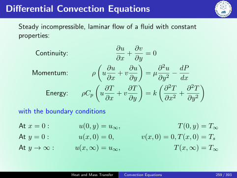
Differential Convection Equations
Steady incompressible, laminar flow of a fluid with constantproperties:
Continuity:∂u
∂x+∂v
∂y= 0
Momentum: ρ
(u∂u
∂x+ v
∂u
∂y
)= µ
∂2u
∂y2− dP
dx
Energy: ρCp
(u∂T
∂x+ v
∂T
∂y
)= k
(∂2T
∂x2+∂2T
∂y2
)with the boundary conditions
At x = 0 : u(0, y) = u∞, T (0, y) = T∞
At y = 0 : u(x, 0) = 0, v(x, 0) = 0, T (x, 0) = Ts
At y →∞ : u(x,∞) = u∞, T (x,∞) = T∞
Heat and Mass Transfer Convection Equations 259 / 393
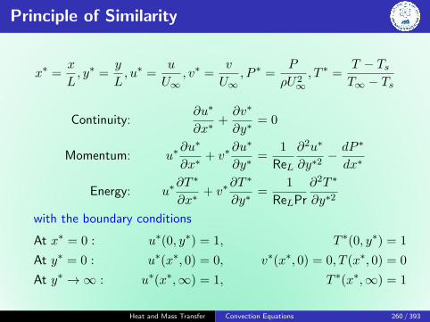
Principle of Similarity
x∗ =x
L, y∗ =
y
L, u∗ =
u
U∞, v∗ =
v
U∞, P ∗ =
P
ρU2∞, T ∗ =
T − TsT∞ − Ts
Continuity:∂u∗
∂x∗+∂v∗
∂y∗= 0
Momentum: u∗∂u∗
∂x∗+ v∗
∂u∗
∂y∗=
1
ReL
∂2u∗
∂y∗2− dP ∗
dx∗
Energy: u∗∂T ∗
∂x∗+ v∗
∂T ∗
∂y∗=
1
ReLPr
∂2T ∗
∂y∗2
with the boundary conditions
At x∗ = 0 : u∗(0, y∗) = 1, T ∗(0, y∗) = 1
At y∗ = 0 : u∗(x∗, 0) = 0, v∗(x∗, 0) = 0, T (x∗, 0) = 0
At y∗ →∞ : u∗(x∗,∞) = 1, T ∗(x∗,∞) = 1
Heat and Mass Transfer Convection Equations 260 / 393

Principle of Similarity
Parameters before nondimensionalizing: L, V, T∞, v, α
Parameters after nondimensionalizing: Re, PrThe number ofparameters is reduced greatly by nondimensionalizing theconvection equations.
Heat and Mass Transfer Convection Equations 261 / 393

Functional Forms
For a given geometry, the solution for u∗ can be expressed as:
u∗ = f1 (x∗, y∗,ReL)
The shear stress at the surface:
τw = µ∂u
∂y
∣∣∣∣y=0
=µU∞L
∂u∗
∂y∗
∣∣∣∣y∗=0
=µU∞L
f2 (x∗,ReL)
Heat and Mass Transfer Convection Equations 262 / 393

Functional Forms
Now the local friction factor:
Cf,x =τw
ρU2∞/2
=µU∞/L
ρU2∞/2
f2 (x∗,ReL)
=2
ReLf2 (x∗,ReL)
Cf,x = f3 (x∗,ReL)
Friction coefficient for a given geometry can be expressed in termsof the Re and the the dimensionless space variable x∗ alone,instead of being expressed in terms of x, L, V, ρ and µ.
This is a very significant finding, and shows the value ofnondimensionalized equations.
Heat and Mass Transfer Convection Equations 263 / 393

Functional Forms
Similary,T ∗ = g1(x∗, y∗,ReL,Pr)
The local convective heat coefficient becomes:
hx = − k
Ts − T∞∂T
∂y
∣∣∣∣y=0
= − k(T∞ − Ts)L(Ts − T∞)
∂T ∗
∂y∗
∣∣∣∣y∗=0
=k
L
∂T ∗
∂y∗
∣∣∣∣y∗=0
Nusselt number relation gives:
Nux =hxL
k=∂T ∗
∂y∗
∣∣∣∣y∗=0
= g2(x∗,ReL,Pr)
The Nu is equivalent to the dimensionless temp. gradient at thesurface, and thus it is properly referred to as the dimensionlessheat transfer coefficient.
Heat and Mass Transfer Convection Equations 264 / 393
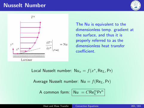
Nusselt Number
The Nu is equivalent to thedimensionless temp. gradient atthe surface, and thus it isproperly referred to as thedimensionless heat transfercoefficient.
Local Nusselt number: Nux = f(x∗,ReL,Pr)
Average Nusselt number: Nu = f(ReL,Pr)
A common form: Nu = CRemL Prn
Heat and Mass Transfer Convection Equations 265 / 393

Momentum and Heat Transfer - Analogy
When Pr = 1, and dP ∗
dx∗ = 0 ( =⇒ u = u∞ in the free stream, asin flow over a flat plate), then
Momentum: u∗∂u∗
∂x∗+ v∗
∂u∗
∂y∗=
1
ReL
∂2u∗
∂y∗2
Energy: u∗∂T ∗
∂x∗+ v∗
∂T ∗
∂y∗=
1
ReL
∂2T ∗
∂y∗2
Profile: u∗ = T ∗
Gradients:∂u∗
∂y∗
∣∣∣∣y∗=0
=∂T ∗
∂y∗
∣∣∣∣y∗=0
Analogy: Cf,xReL
2= Nux
Reynolds analogy
h for fluid with Pr ≈ 1 from Cf which is easier to measure.
Heat and Mass Transfer Convection Equations 266 / 393

Stanton Number
St =h
ρCpV=
Nu
ReLPr
Cf,x2
= Stx (Pr = 1)
Stanton number is also a dimensionless heat transfer coefficient. Itmeasures the ratio of heat transferred into a fluid to the thermalcapacity of fluid.
Reynolds analogy is limited to Pr = 1, and dP ∗
dx∗ = 0.
An analogy that is applicable over a wide range of Pr by adding aPrandtl number correction.
Heat and Mass Transfer Convection Equations 267 / 393

Modified Reynolds or Chilton-Colburn Analogy
Laminar flow over a flat plate
Cf,x = 0.664Re−1/2x
Nu = 0.332Pr1/3Re1/2x
Cf,xReL
2= NuxPr−1/3
=⇒Cf,x
2= StPr2/3 ≡ jH
0.6 < Pr < 60
Here jH is called the Colburn j-factor.
Experiments show that it may be applied for turbulent flow over asurface, even in the presence of pressure gradients (dP
∗
dx∗ 6= 0).
However, the analogy is not applicable for laminar flow unlessdP ∗
dx∗ = 0. Therefore, it does not apply to laminar flow in a pipe.
Heat and Mass Transfer Convection Equations 268 / 393

Heat and Mass Transfer Convection Equations 269 / 393

Heat and Mass Transfer
External Flow
Sudheer Siddapuredddy
Department of Mechanical EngineeringIndian Institution of Technology Patna
Heat and Mass Transfer External Flow 270 / 393

Heat Transfer
Local Nusselt number: Nux = f(x∗,ReL,Pr)
Average Nusselt number: NuL = f(ReL,Pr)
A common form: NuL = CRemL Prn
The Empirical Method
Heat and Mass Transfer External Flow 271 / 393

Heat Transfer
Tf ≡Ts + T∞
2
Heat and Mass Transfer External Flow 272 / 393

Flat Plate in Parallel Flow
Assumptions
Steady, incompressible, laminar flow with constant fluid propertiesand negligible viscous dissipation.
Heat and Mass Transfer External Flow 273 / 393

Flat Plate in Parallel Flow
Continuity:∂u
∂x+∂v
∂y= 0
Momentum: u∂u
∂x+ v
∂u
∂y= ν
∂2u
∂y2
Energy: u∂T
∂x+ v
∂T
∂y= α
∂2T
∂y2
First solved in 1908 by German engineer H. Blasius, a student ofL. Pradtl. The profile u/u∞ remains unchanged with y/δ. Astream function ψ(x, y) is defined as,
u =∂ψ
∂yand v = −∂ψ
∂x
This takes care of continuity equation.Heat and Mass Transfer External Flow 274 / 393

Flat Plate in Parallel Flow
A dimensionless independent similarity variable and a dependentvariable such that u/u∞ = f ′(η),
η = y
√u∞νx
and f(η) =ψ
u∞√νx/u∞
u =∂ψ
∂y=∂ψ
∂η
∂η
∂y= u∞
df
dη= u∞f
′
v = −∂ψ∂x
=1
2
√νu∞x
(ηdf
dη− f
)(∵ −2x∂f∂x = η ∂f∂η )
2f ′′′ + ff ′′ = 0
The problem reduced to one of solving a nonlinear third-orderordinary differential equation.
Heat and Mass Transfer External Flow 275 / 393
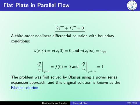
Flat Plate in Parallel Flow
2f ′′′ + ff ′′ = 0
A third-order nonlinear differential equation with boundaryconditions:
u(x, 0) = v(x, 0) = 0 and u(x,∞) = u∞
df
η
∣∣∣∣η=0
= f(0) = 0 anddf
η
∣∣∣∣η→∞
= 1
The problem was first solved by Blasius using a power seriesexpansion approach, and this original solution is known as theBlasius solution.
Heat and Mass Transfer External Flow 276 / 393
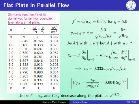
Flat Plate in Parallel Flow
f ′ = u/u∞ = 0.99, for η = 5.0
yη=5.0 = δ =5.0√u∞/νx
=5x√Rex
As δ ↑ with x, ν ↑ but δ ↓ with u∞ ↑
τw = µ∂u
∂y
∣∣∣∣y=0
= µu∞
√u∞νx
d2f
dη2
∣∣∣∣η=0
=⇒ τw = 0.332u∞√u∞/νx
Cf,x =τw
ρu2∞/2
= 0.664Re−1/2x
Unlike δ, τw and Cf,x decrease along the plate as x−1/2.
Heat and Mass Transfer External Flow 277 / 393
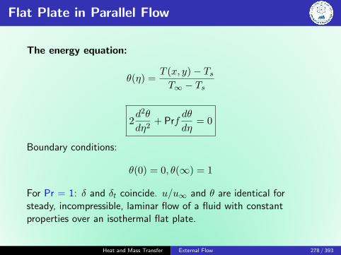
Flat Plate in Parallel Flow
The energy equation:
θ(η) =T (x, y)− TsT∞ − Ts
2d2θ
dη2+ Prf
dθ
dη= 0
Boundary conditions:
θ(0) = 0, θ(∞) = 1
For Pr = 1: δ and δt coincide. u/u∞ and θ are identical forsteady, incompressible, laminar flow of a fluid with constantproperties over an isothermal flat plate.
Heat and Mass Transfer External Flow 278 / 393

Flat Plate in Parallel Flow
2d2θ
dη2+ Prf
dθ
dη= 0
For Pr > 0.6,dθ
dη
∣∣∣∣η=0
= 0.332 Pr1/3
dT
dy
∣∣∣∣y=0
= 0.332 Pr1/3(T∞ − Ts)√u∞νx
hx = 0.332 Pr1/3k
√u∞νx
Nux = 0.332 Re1/2x Pr1/3
δt =δ
Pr1/3=
5x
Pr1/3√
Rex(Tf = (Ts + T∞)/2)
Heat and Mass Transfer External Flow 279 / 393

Turbulent Flow
Rex =ρu∞x
µRecr = 5× 10⁵
Heat and Mass Transfer External Flow 280 / 393

Turbulent Flow
Laminar: δv,x =5x
Re1/2x
and Cf,x =0.664
Re1/2x
, Rex < 5× 10⁵
Turbulent: δv,x =0.382x
Re1/5x
and Cf,x =0.0592
Re1/5x
, 5× 10⁵ ≤ Rex ≤ 107
Average skin friction coefficient
Laminar : Cf =1
L
L∫0
Cf,xdx =1.328
Re1/2L
, Rex < 5× 10⁵
Turbulent : Cf =0.074
Re1/5L
, 5× 10⁵ ≤ Rex ≤ 107
Heat and Mass Transfer External Flow 281 / 393

Turbulent Flow
Cf =1
L
xcr∫0
Cf,lamdx+
L∫xcr
Cf,turbdx
Cf =0.074
Re1/5L
− 1742
ReL
(5× 10⁵ ≤ Rex ≤ 107)
Rough surface, turbulent: Cf =(
1.89− 1.62 logε
L
)−2.5
(Re > 106, ε/L > 10−4)
Heat and Mass Transfer External Flow 282 / 393

Turbulent Flow
Laminar: Nux =hxx
k= 0.332Re0.5
x Pr1/3 (Pr > 0.6)
Turbulent: Nux =hxx
k= 0.0296Re0.8
x Pr1/3 (0.6 ≤Pr ≤ 60)
(5× 10⁵ ≤ Rex ≤ 107)
Average values:
Nulam =hL
k= 0.664Re0.5
x Pr1/3
Nuturb =hL
k= 0.037Re0.8
x Pr1/3
Heat and Mass Transfer External Flow 283 / 393

Turbulent Flow
h =1
L
xcr∫0
hx,lamdx+
L∫xcr
hx,turbdx
Nu =(0.037Re0.8
L − 871)
Pr1/3
(0.6 ≤Pr ≤ 60)
(5× 10⁵ ≤ ReL ≤ 107)
Heat and Mass Transfer External Flow 284 / 393

Other Configurations
Liquid metalsSuch as mercury have high k, very small Pr. Thus, the δt developsmuch faster than δ.
We can assume the velocity in δt to be constant at the free streamvalue and solve the energy equation.
Nux = 0.565(RexPr)1/2 = 0.565Pe1/2x (Pr < 0.05,Pex ≥ 100)
Churchill’s correlation for all Prandtl numbers
Nux =0.3387Re
1/2x Pr1/3[
1 + (0.0468/Pr)2/3]1/4
(RexPr ≥ 100)
Heat and Mass Transfer External Flow 285 / 393

Flat Plate with Unheated Starting Length
Laminar: Nux =Nux|ξ=0[
1− (ξ/x)3/4]1/3 =
0.332Re0.5x Pr1/3[
1− (ξ/x)3/4]1/3
Turbulent: Nux =Nux|ξ=0[
1− (ξ/x)9/10]1/9 =
0.0296Re0.8x Pr1/3[
1− (ξ/x)9/10]1/9
Heat and Mass Transfer External Flow 286 / 393

Flat Plate with Uniform Heat Flux
Laminar: Nux = 0.453Re0.5x Pr1/3
Turbulent: Nux = 0.0308Re0.8x Pr1/3
Net heat transfer from the surface:
Q = qsAs
qs = hx[Ts(x)− T∞]
=⇒ Ts(x) = T∞ +qshs
Heat and Mass Transfer External Flow 287 / 393

Problem
Engine oil at 60◦C flows over the upper surface of a 5 m long flatplate whose temperature is 20◦C with a velocity of 2 m/s.Determine the total drag force and the rate of heat transfer perunit width of the entire plate.
Tf = 40◦C
ρ = 876 kg/m3
Pr = 2870
k = 0.144 W/m K
ν = 242× 10−6 m2/s
Known: Engine oil flows over a flat plate.
Heat and Mass Transfer External Flow 288 / 393

Solution
Find: Total drag force, Q per unit width of plate.Assumptions: The flow is steady, incompressible
ReL =u∞L
ν= 41322.3 (< Recr = 5× 10⁵)
Cf = 1.328Re−1/2L = 6.533× 10−0.3
FD = CfAsρu2∞
2= 57.23 N
Nu = 0.664Re1/2L Pr1/3 = 1938.5
h =k
LNu = 55.98 W/m2 K
Q = hAs(T∞ − Ts) = 11.2 W
Heat and Mass Transfer External Flow 289 / 393
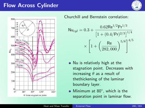
Flow Across Cylinder
Churchill and Bernstein correlation:
Nucyl = 0.3 +0.62Re1/2Pr1/3[
1 + (0.4/Pr)2/3]1/4
×
[1 +
(Re
282, 000
)5/8]4/5
Nu is relatively high at thestagnation point. Decreases withincreasing θ as a result ofthethickening of the laminarboundary layer.
Minimum at 80◦, which is theseparation point in laminar flow.
Heat and Mass Transfer External Flow 290 / 393

Flow Across Cylinder
Increases with increasing as a resultof the intense mixing in theseparated flow region (the wake).
The sharp increase at about 90◦ isdue to the transition from laminarto turbulent flow.
The later decrease is again due tothe thickening of the boundarylayer.
Nu reaches its second minimum atabout 140◦, which is the flowseparation point in turbulent flow,and increases with as a result ofthe intense mixing in the turbulentwake region.
Heat and Mass Transfer External Flow 291 / 393
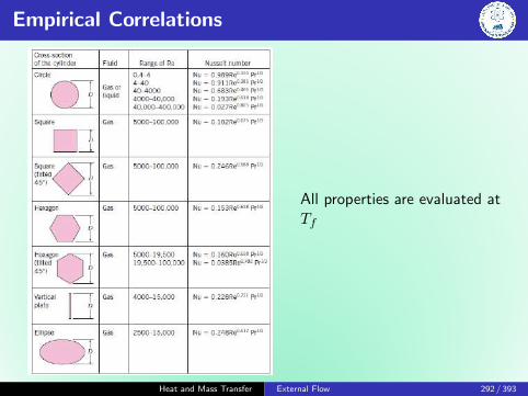
Empirical Correlations
All properties are evaluated atTf
Heat and Mass Transfer External Flow 292 / 393

Flow Across Tube Banks
ST Transverse pitchSL Longitudinal pitchSD Diagonal pitch
NuD =hD
k= C RemDPrn(Pr/Prs)
0.25
ReD is defined at umaxbut not the u∞.
All properties except Prsare evaluated at(Tinlet +Toutlet)/2 of fluid.
Prs is evaluated at Ts.
Heat and Mass Transfer External Flow 293 / 393

Flow Across Tube Banks
NuD,NL<16= FNuD
Heat and Mass Transfer External Flow 294 / 393

Methodology for a Convection Calculation
Become immediately cognizant of the flow geometry.
Specify the appropriate reference temperature and evaluatethe pertinent fluid properties at that temperature.
Calculate the Reynolds number.
Decide whether a local or surface average coefficient isrequired.
Select the appropriate correlation.
Heat and Mass Transfer External Flow 295 / 393
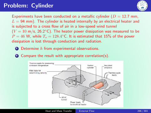
Problem: Cylinder
Experiments have been conducted on a metallic cylinder (D = 12.7 mm,L = 94 mm). The cylinder is heated internally by an electrical heater andis subjected to a cross flow of air in a low-speed wind tunnel(V = 10 m/s, 26.2◦C). The heater power dissipation was measured to beP = 46 W, while Ts = 128.4◦C. It is estimated that 15% of the powerdissipation is lost through conduction and radiation.
1 Determine h from experimental observations.
2 Compare the result with appropriate correlation(s).
Heat and Mass Transfer External Flow 296 / 393

Problem: Cylinder
Experiments have been conducted on a metallic cylinder (D = 12.7 mm,L = 94 mm). The cylinder is heated internally by an electrical heater andis subjected to a cross flow of air in a low-speed wind tunnel(V = 10 m/s, 26.2◦C). The heater power dissipation was measured to beP = 46 W, while Ts = 128.4◦C. It is estimated that 15% of the powerdissipation is lost through conduction and radiation.
NuD = 0.26 Re0.6D Pr0.37 (Pr/Prs)1/2 (Zhukauskasa relation)
Air (T∞ = 26.2◦C):ν = 15.89× 10⁻⁶ m2/s, k = 26.3× 10⁻³ W/m K, Pr = 0.707
Air (Tf = 77.3◦C):ν = 20.92× 10⁻⁶ m2/s, k = 30× 10−3 W/m K, Pr = 0.700
Air (Ts = 128.4◦C): Pr = 0.690
NuD = 0.3 +0.62Re
1/2D Pr1/3[
1 + (0.4/Pr)2/3]1/4
[1 +
(ReD
282, 000
)5/8]4/5
(Churchill relation)
Heat and Mass Transfer External Flow 297 / 393
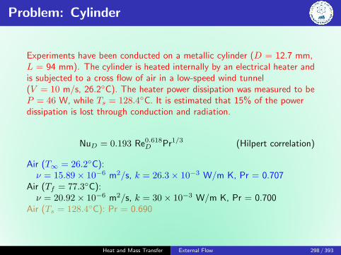
Problem: Cylinder
Experiments have been conducted on a metallic cylinder (D = 12.7 mm,L = 94 mm). The cylinder is heated internally by an electrical heater andis subjected to a cross flow of air in a low-speed wind tunnel(V = 10 m/s, 26.2◦C). The heater power dissipation was measured to beP = 46 W, while Ts = 128.4◦C. It is estimated that 15% of the powerdissipation is lost through conduction and radiation.
NuD = 0.193 Re0.618D Pr1/3 (Hilpert correlation)
Air (T∞ = 26.2◦C):ν = 15.89× 10⁻⁶ m2/s, k = 26.3× 10⁻³ W/m K, Pr = 0.707
Air (Tf = 77.3◦C):ν = 20.92× 10⁻⁶ m2/s, k = 30× 10−3 W/m K, Pr = 0.700
Air (Ts = 128.4◦C): Pr = 0.690
Heat and Mass Transfer External Flow 298 / 393

Problem: Sphere
The decorative plastic film on a copper sphere of 10 mm diameteris cured in an oven at 75◦C. Upon removal from the oven, thesphere is subjected to an airstream at 1 atm and 23◦C having avelocity of 10 m/s. Estimate how long it will take to cool thesphere to 35◦C.Copper (T = 55◦C):ρ = 8933 kg/m3, k = 399 W/m K, Cp = 387 J/kg
Air (T∞ = 23◦C):µ = 181.6× 10⁻⁷ Ns/m2, ν = 15.36× 10⁻⁶ m2/s,
k = 0.0258 W/m K, Pr = 0.709Air (Ts = 55◦C): µ = 197.8× 10⁻⁷ Ns/m2
NuD = 2 +(
0.4 Re1/2D + 0.06 Re
2/3D
)Pr0.4
(µ
µs
)1/4
All properties except µs are evaluated at T∞.
Heat and Mass Transfer External Flow 299 / 393

Problem: Sphere
The decorative plastic film on a copper sphere of 10 mm diameteris cured in an oven at 75◦C. Upon removal from the oven, thesphere is subjected to an airstream at 1 atm and 23◦C having avelocity of 10 m/s. Estimate how long it will take to cool thesphere to 35◦C.Copper (T = 55◦C):ρ = 8933 kg/m3, k = 399 W/m K, Cp = 387 J/kg
Air (T∞ = 39◦C):ν = 17.15× 10⁻⁶ m2/s, Pr = 0.705
Air (Ts = 55◦C): µ = 197.8× 10⁻⁷ Ns/m2
All propertiesare evaluated atTf
Heat and Mass Transfer External Flow 300 / 393

Quiz 4
A flat plate of 0.3 m long is maintained at a uniform surfacetemperature, Ts = 230◦C, by using two independently controlledelectrical strip heaters. The first heater 0.2 m long and the secondone is 0.1 m long. The ambient air temperature at T∞ = 25◦Cflows over the plate at a velocity of 60 m/s. At what heater is theelectrical input a maximum? What is the value of this input.
Air (Tf = 400 K):ν = 26.41× 10⁻⁶ m2/s, k = 0.0338 W/m K, Pr = 0.69
Relations
Laminar boundary layer Nux =hxx
k= 0.664 Re1/2
x Pr1/3
(Re < 5× 10⁵)
Mixed boundary layer NuL =hLL
k= (0.037 Re
4/5L − 871) Pr1/3
(Re > 5× 10⁵)
Heat and Mass Transfer External Flow 301 / 393
Heat and Mass Transfer
Internal Flow
Sudheer Siddapuredddy
Department of Mechanical EngineeringIndian Institution of Technology Patna
Heat and Mass Transfer Internal Flow 302 / 393

Internal Flows
External flow
Fluid has a free surface
δ is free to grow indefinitely
Internal flow
Fluid is completely confined by the inner surfaces of the tube
There is a limit on how much δ can grow
Circular pipes can withstand largepressure difference between insideand outside without distortion.Provide the most heat transferfor the least pressure drop.
Heat and Mass Transfer Internal Flow 303 / 393

Internal Flows
ReD =ρumD
µ
Critical ReD,c ≈ 2300
Laminar(xfd,h
D
)lam≈ 0.05ReD
Turbulence(xfd,h
D
)turb≈ 10
Heat and Mass Transfer Internal Flow 304 / 393

Mean Velocity
m = ρumAc =
∫Ac
ρu(r, x)dAc
um =2
r2o
ro∫0
u(r, x)rdr
Heat and Mass Transfer Internal Flow 305 / 393

Velocity Profile in Fully Developed Region
Assumptions: Laminar, incompressible, constant property fluid infully developed region, circular
tube.
u(r) = − 1
4µ
(dp
dx
)r2o
[1−
(r
ro
)2]
um = − r2o
8µ
dp
dx
u(r)
um= 2
[1−
(r
ro
)2]
Heat and Mass Transfer Internal Flow 306 / 393

Friction Factor
The Moody (or Darcy) friction factor:
f ≡ −(dp/dx)D
ρu2m/2
Friction coefficient, Fanning friction factor,
Cf =τs
ρu2m/2
=f
4
For laminar flow:
f =64
Re
For turbulent flow:
f = 0.316Re−1/4D ReD . 2× 10⁴
f = 0.184Re−1/5D ReD & 2× 10⁴
Heat and Mass Transfer Internal Flow 307 / 393

Moody Diagram
Heat and Mass Transfer Internal Flow 308 / 393
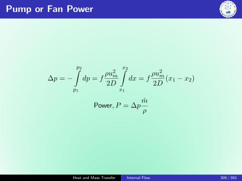
Pump or Fan Power
∆p = −p2∫p1
dp = fρu2
m
2D
x2∫x1
dx = fρu2
m
2D(x1 − x2)
Power, P = ∆pm
ρ
Heat and Mass Transfer Internal Flow 309 / 393

Temperature
ReD =ρumD
µ
Critical ReD,c ≈ 2300
Laminar(xfd,t
D
)lam≈ 0.05ReDPr
Turbulence(xfd,t
D
)turb≈ 10
Heat and Mass Transfer Internal Flow 310 / 393

Mean Temperature
Advection rate: integrating the product of mass flux (ρu) and thethermal energy (or enthalpy) per unit mass, CpT , over Ac.
mCpTm =
∫Ac
ρuCpTdAc
For incompressible flow in acircular tube with constant Cp:
Tm =2
umr2o
ro∫0
uTrdr
q′′s = h(Ts − Tm)
Heat and Mass Transfer Internal Flow 311 / 393

Dimensionless Temperature
∂
∂x
[Ts(x)− T (r, x)
Ts(x)− Tm(x)
]fd,t
= 0
=⇒ ∂
∂x
[Ts(x)− T (r, x)
Ts(x)− Tm(x)
]fd,t
=−∂T/∂r|r=roTs − Tm
6= f(x)
q′′s = −k ∂T∂y
∣∣∣∣y=0
= −k ∂T∂r
∣∣∣∣r=ro
=⇒ h
k6= f(x)
In thermally fully developed flow of a fluid with constantproperties, hlocal is a constant, independent of x.
Heat and Mass Transfer Internal Flow 312 / 393

Heat Transfer Coefficient for Flow in a Tube
Heat and Mass Transfer Internal Flow 313 / 393

General Considerations
dqconv = mCp[(Tm + dTm)− Tm]
dqconv = mCpdTm
Heat and Mass Transfer Internal Flow 314 / 393
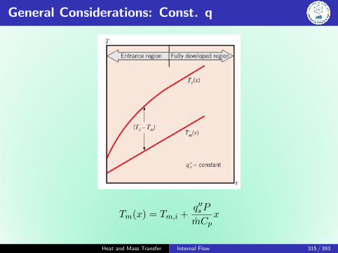
General Considerations: Const. q
Tm(x) = Tm,i +q′′sP
mCpx
Heat and Mass Transfer Internal Flow 315 / 393

General Considerations: Const. T
Ts − Tm(x)
Ts − Tm,i= exp
(− Px
mCph
)Heat and Mass Transfer Internal Flow 316 / 393

Fully Developed Laminar Flow: Const. q
u∂T
∂x=α
r
∂
∂r
(r∂T
∂r
)T (r, x) =⇒ Tm(x)− Ts(x) = −11
48
q′′sD
k
h =11
48
k
D=⇒ NuD =
hD
k= 4.36
Heat and Mass Transfer Internal Flow 317 / 393
Fully Developed Laminar Flow: Const. T
NuD =hD
k= 3.66
Heat and Mass Transfer Internal Flow 318 / 393

The Entry Region
Heat and Mass Transfer Internal Flow 319 / 393

Turbulent Flow in Circular Tubes
Dittus-Boelter equation
NuD = 0.023Re4/5D Prn
where n = 0.4 for heating (Ts > Tm) and 0.3 for cooling(Ts < Tm).
Heat and Mass Transfer Internal Flow 320 / 393

The Entry Region
Heat and Mass Transfer Internal Flow 321 / 393

The Entry Region
Heat and Mass Transfer Internal Flow 322 / 393

Heat and Mass Transfer
Free Convection
Sudheer Siddapuredddy
Department of Mechanical EngineeringIndian Institution of Technology Patna
Heat and Mass Transfer Free Convection 323 / 393

Physical Considerations
Buoyancy
Combined presence of a fluid density gradient and a body forcethat is proportional to density.
Body Force
Gravitational
Centrifugal force in rotating fluid machinery
Coriolis force in atmospheric
Oceanic rotational motions
Heat and Mass Transfer Free Convection 324 / 393

Free Convection: Examples
Heat and Mass Transfer Free Convection 325 / 393

Conditions of Stable & Unstable T Gradient
Classification: bounded or unbounded
Free boundary flows
Bounded by a surface
Heat and Mass Transfer Free Convection 326 / 393

Free Boundary Flows
May occur in the form of a plume or a buoyant jet. plume isassociated with fluid rising from a submerged heated object.
A heated wire immersed in an extensive, quiescent fluid.
Heat and Mass Transfer Free Convection 327 / 393

Heated Vertical Plate
Momentum: u∂u
∂x+ v
∂u
∂y= −1
ρ
∂P
∂x+
1
ρX + ν
∂2u
∂y2
Heat and Mass Transfer Free Convection 328 / 393

Buoyancy Force
Force by gravity per unit volume:
X = −ρg
=⇒ u∂u
∂x+ v
∂u
∂y= −1
ρ
∂P
∂x− g + ν
∂2u
∂y2
From y-momentum equation: (∂p/∂y) = 0
∂P
∂x= −ρ∞g
=⇒ u∂u
∂x+ v
∂u
∂y= g
∆ρ
ρ+ ν
∂2u
∂y2
where ∆ρ = ρ∞ − ρ
Heat and Mass Transfer Free Convection 329 / 393
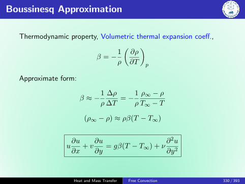
Boussinesq Approximation
Thermodynamic property, Volumetric thermal expansion coeff.,
β = −1
ρ
(∂ρ
∂T
)p
Approximate form:
β ≈ −1
ρ
∆ρ
∆T= −1
ρ
ρ∞ − ρT∞ − T
(ρ∞ − ρ) ≈ ρβ(T − T∞)
u∂u
∂x+ v
∂u
∂y= gβ(T − T∞) + ν
∂2u
∂y2
Heat and Mass Transfer Free Convection 330 / 393
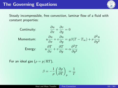
The Governing Equations
Steady incompressible, free convection, laminar flow of a fluid withconstant properties:
Continuity:∂u
∂x+∂v
∂y= 0
Momentum: u∂u
∂x+ v
∂u
∂y= gβ(T − T∞) + ν
∂2u
∂y2
Energy: u∂T
∂x+ v
∂T
∂y= α
∂2T
∂y2
For an ideal gas (ρ = p/RT ),
β = −1
ρ
(∂ρ
∂T
)p
=1
T
Heat and Mass Transfer Free Convection 331 / 393

Dimensionless Parameters
x∗ ≡ x
L, y∗ ≡ y
L, u∗ ≡ u
u0, v∗ ≡ v
u0, T ∗ ≡ T − T∞
Ts − T∞u0 is an arbitrary reference velocity.
Momentum: u∗∂u∗
∂x∗+ v∗
∂u∗
∂y∗=gβ(Ts − T∞)L
u20
T ∗ +1
ReL
∂2u∗
∂y∗2
Energy: u∗∂T ∗
∂x∗+ v∗
∂T ∗
∂y∗=
1
ReLPr
∂2T ∗
∂y∗2
Coefficient of T ∗ is in terms of unknown reference velocity u0.Eliminate it to get a dimensionless parameter:
GrL ≡gβ(Ts − T∞)L
u20
(u0L
ν
)2
=gβ(Ts − T∞)L3
ν2
Heat and Mass Transfer Free Convection 332 / 393

Grashof number
GrL ≡gβ(Ts − T∞)L3
ν2=
Buoyancy force
Viscous force
GrL
Re2L
� 1 : Free convection is neglected
NuL = f(ReL, Pr)
Gr
Re2 � 1 : Forced convection is neglected
NuL = f(GrL, Pr)
Gr
Re2 ≡ 1 : Combination of free and forced
Heat and Mass Transfer Free Convection 333 / 393

Similarity Solution
Boundary conditions:
At y = 0 : u = v = 0, T = Ts
At y →∞ : u→ 0, T → T∞
Similarity parameter of the form:
η ≡ y
x
(Grx4
)1/4
and representing the velocity components in terms of a streamfunction defined as:
ψ(x, y) ≡ f(η)
[4ν
(Grx4
)1/4]
u =∂ψ
∂y=∂ψ
∂η
∂η
∂y=
2ν
xGr1/2x f ′(η)
Heat and Mass Transfer Free Convection 334 / 393

Similarity Solution
v = −∂ψ∂x
and T ∗ ≡ T − T∞Ts − T∞
The reduced partial differential equations:
f ′′′ + 3ff ′′ − 2(f ′)2 + T ∗ = 0
T ∗′′
+ 3PrfT ∗′
= 0
Boundary conditions:
At η = 0 : f = f ′ = 0, T ∗ = 1
At η →∞ : f ′ → 0, T ∗ → 0
Heat and Mass Transfer Free Convection 335 / 393

Laminar, Free Convection
Laminar, free convection boundary layer conditions on a isothermalvertical surface.
Heat and Mass Transfer Free Convection 336 / 393

Laminar, Free Convection
Newton’s law of cooling:
Nux =hx
k=
[q′′s/(Ts − T∞)]x
k
Fourier’s law:
q′′s = −k ∂T∂y
∣∣∣∣y=0
= −kx
(Ts − T∞)
(Grx4
)1/4 dT ∗
dη
∣∣∣∣η=0
=⇒ Nux =hx
k= −
(Grx4
)1/4 dT ∗
dη
∣∣∣∣η=0
=
(Grx4
)1/4
g(Pr)
g(Pr) =0.75Pr1/2
(0.609 + 1.221Pr1/2 + 1.238Pr)1/4
0 ≤ Pr ≤ ∞Heat and Mass Transfer Free Convection 337 / 393

Laminar, Free Convection
h=1
L
L∫0
hdx =k
L
[gβ(Ts − T∞)
4ν2
]1/4
g(Pr)
L∫0
dx
x1/4
NuL =hL
k=
4
3
(GrL4
)1/4
g(Pr)
NuL = 43 NuL
These results apply irrespective of whether Ts > T∞ or Ts < T∞.
Heat and Mass Transfer Free Convection 338 / 393

Turbulence
Critical Rayleigh number:
Rax,c = Grx,c Pr =gβ(Ts − T∞)x3
να≈ 109
Heat and Mass Transfer Free Convection 339 / 393

Problem
Consider a 0.25 m long vertical plate that is at 70◦C. The plate issuspended in air that is at 25◦C. Estimate the boundary layerthickness at the trailing edge of the plate if the air is quiescent.How does this thickness compare with that which would exist if theair were flowing over the plate at a free stream velocity of 5 m/s?
Air properties at Tf = 47.5◦C:ν = 17.95× 10⁻⁶ m2/s, Pr = 0.7, β = 1
Tf= 3.12× 10⁻³ K−1
Heat and Mass Transfer Free Convection 340 / 393

Solution
Air properties at Tf = 47.5◦C:ν = 17.95× 10⁻⁶ m2/s, Pr = 0.7, β = 1
Tf= 3.12× 10⁻³ K−1
GrL =gβ(Ts − T∞)L3
ν2= 6.69× 10⁷
RaL = GrL Pr = 4.68× 10⁷
For Pr = 0.7, η ≈ 6.0 at the edge of the boundary layer.
η ≡ y
x
(Grx4
)1/4
= 0.6 =⇒ δL = 0.37 m
Heat and Mass Transfer Free Convection 341 / 393

Solution
Air properties at Tf = 47.5◦C:ν = 17.95× 10⁻⁶ m2/s, Pr = 0.7, β = 1
Tf= 3.12× 10⁻³ K−1
For airflow at u∞ = 5 m/s
ReL =u∞L
ν= 6.97× 10⁴
For laminar boundary layer:
δ =5x√ReL
= 0.0047 mδ
δt≈ Pr1/3
Heat and Mass Transfer Free Convection 342 / 393

Solution
Comments
δ are typically larger for free convection than for forcedconvection.
Gr /Re2 � 1, and the assumption of negligible buoyancyeffects for u∞ = 5 m/s is justified.
Heat and Mass Transfer Free Convection 343 / 393

Empirical Correlations
Nu =h
Lck = C(GrL Pr)n = C RanL
RaL = GrL Pr =gβ(Ts − T∞)L3
να
Properties of the fluid are calculated at the mean film temperature,Tf ≡ (Ts + T∞)/2.
Heat and Mass Transfer Free Convection 344 / 393

Empirical Correlations
Heat and Mass Transfer Free Convection 345 / 393

Empirical Correlations
Heat and Mass Transfer Free Convection 346 / 393

Combined Free and Forced Convection
Nuncombined = (NunForced±NunNatural)
Heat and Mass Transfer Free Convection 347 / 393

Inclined Plate
Heat and Mass Transfer Free Convection 348 / 393

Horizontal Plate
Heat and Mass Transfer Free Convection 349 / 393

Heat and Mass Transfer
Boiling and Condensation
Sudheer Siddapuredddy
Department of Mechanical EngineeringIndian Institution of Technology Patna
Heat and Mass Transfer Boiling and Condensation 350 / 393

Physical Considerations
Free and Forced convection depends onρ, Cp, µ, kfluid
Boiling/Condensation Heat Transfer depends on
ρ, Cp, µ, kfluid
∆T = |Ts − Tsat|Latent heat of vaporization, hfg
Surface tension at the liquid-vapor interface, σ
body force arising from the liquid-vapor density difference,g(ρl − ρv)
h = h[∆T, g(ρl − ρv), hfg, σ, L, ρ, Cp, k, µ]
10 variables in 5 dimensions =⇒ 5 pi-groups.
Heat and Mass Transfer Boiling and Condensation 351 / 393

Dimensionless Parameters
hL
k= f
[ρg(ρl − ρv)L3
µ2,Cp∆T
hfg,µCpk,g(ρl − ρv)L2
σ
]NuL = f
[ρg(ρl − ρv)L3
µ2, Ja,Pr,Bo
]Jakob number
Ratio of max sensible energy absorbed by liquid (vapor) to latentenergy absorbed by liquid (vapor) during condensation (boiling).
Bond number
Ratio of the buoyancy force to the surface tension force.
Unnamed parameter
Represents the effect of buoyancy-induced fluid motion on heattransfer.
Heat and Mass Transfer Boiling and Condensation 352 / 393

Boiling and Evaporation
Boiling
The process of addition of heat to a liquid sucha way that generation of vapor occurs.
Solid-liquid interface
Characterized by the rapid formation of vaporbubbles
Evaporation
Liquid-vapor interface
Pv < Psat of the liquid at a given temp
No bubble formation or bubble motion
Heat and Mass Transfer Boiling and Condensation 353 / 393

Boiling
Boiling occurs
Solid-liquid interface
when a liquid is brought into contact with a surface at atemperature above the saturation temperature of the liquid
Heat and Mass Transfer Boiling and Condensation 354 / 393

Bubble
The boiling processes in practice do not occur underequilibrium conditions.
Bubbles exist because of the surface tension at the liquidvapor interface due to the attraction force on molecules at theinterface toward the liquid phase.
The temperature and pressure of the vapor in a bubble areusually different than those of the liquid.
Surface tension ↓ ↑ Temperature
Surface tension = 0 at critical temperature
No bubbles at supercritical pressures and temperatures
Heat and Mass Transfer Boiling and Condensation 355 / 393

Boiling - Classification
Pool boiling
Fluid is stationary
Fluid motion is due tonatural convection currents
Motion of bubbles under theinfluence of buoyancy
Flow boiling
Fluid is forced to move in aheated pipe or surface byexternal means such aspump
Always accompanied byother convection effects
Heat and Mass Transfer Boiling and Condensation 356 / 393
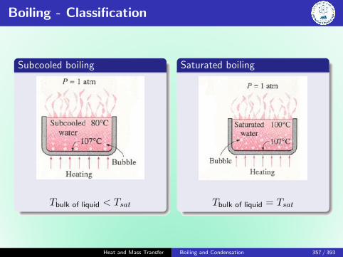
Boiling - Classification
Subcooled boiling
Tbulk of liquid < Tsat
Saturated boiling
Tbulk of liquid = Tsat
Heat and Mass Transfer Boiling and Condensation 357 / 393

Boiling Regimes - Nukiyama, 1934
Boiling curve for saturated water at atmospheric pressure
Heat and Mass Transfer Boiling and Condensation 358 / 393

Boiling Regimes - Nukiyama, 1934
Heat and Mass Transfer Boiling and Condensation 359 / 393

Boiling Regimes
Methanol on horizontal 1 cm steam-heated copper tube
Heat and Mass Transfer Boiling and Condensation 360 / 393

Boiling Regimes
Natural convection
Governed by natural convection currents
Heat transfer from the heating surface to thefluid is by natural convection
Nucleate boiling
Stirring and agitation caused by the entrainmentof the liquid to the heater surface increases h, q′′
High heat transfer rates are achieved
Heat and Mass Transfer Boiling and Condensation 361 / 393

Boiling Regimes
Transition boiling
Unstable film boiling
Governed by natural convection currents
Heat transfer from the heating surface to thefluid is by natural convection
Film boiling
Presence of vapor film is responsible for the lowheat transfer rates
Heat transfer rate increases with increasing ∆Teas a result of heat transfer from the heatedsurface to the liquid through the vapor film byradiation.
Heat and Mass Transfer Boiling and Condensation 362 / 393

Boiling Nucleation - Boiling Inception
The process of bubble formation is called Nucleation
The cracks and crevices do not constitute nucleation sites forthe bubbles. Must contain pockets of gas/air trapped
It is from these pockets of trapped air that the vapor bubblesbegin to grow during nucleate boiling
These cavities are the sites at which bubble nucleation occurs
Heat and Mass Transfer Boiling and Condensation 363 / 393
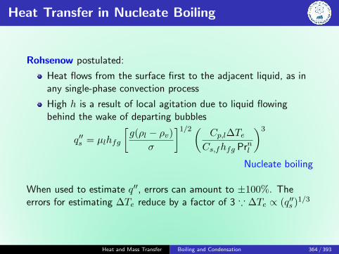
Heat Transfer in Nucleate Boiling
Rohsenow postulated:
Heat flows from the surface first to the adjacent liquid, as inany single-phase convection process
High h is a result of local agitation due to liquid flowingbehind the wake of departing bubbles
q′′s = µlhfg
[g(ρl − ρv)
σ
]1/2( Cp,l∆TeCs,fhfg Prnl
)3
Nucleate boiling
When used to estimate q′′, errors can amount to ±100%. Theerrors for estimating ∆Te reduce by a factor of 3 ∵ ∆Te ∝ (q′′s )1/3
Heat and Mass Transfer Boiling and Condensation 364 / 393

Heat Transfer in Nucleate Boiling
Heat and Mass Transfer Boiling and Condensation 365 / 393

Critical Heat Flux
Zuber’s correlations for flat horizontal plate:
q′′max = 0.149hfgρv
[g(ρl − ρv)
σ
]1/4
Critical heat flux
Heat and Mass Transfer Boiling and Condensation 366 / 393

Leidenfrost Temperature
Rewetting of hot surfaces: Liquid does not we hot surface.
q′′min = Chfgρv
[gσ(ρl − ρv)(ρl + ρv)2
]1/4
C is a non-dimensional constant which lies between 0.09 and 0.18.
C = 0.09 provides a better fit.
C = 0.13 is sometimes taken as an intermediate value
Heat and Mass Transfer Boiling and Condensation 367 / 393

Prof. Dr. Johann G. Leidenfrost (1715-1794)
Father - Minister
Started off with Theological studies
PhD thesis, ‘’On the HarmoniousRelationship of Movements in theHuman Body”
Professor at University of Duisburg
Areas of influences:
TheologianPhysician (Private Medical practice)As a Prof. taught:Medicine, Physics, and Chemistry
Heat and Mass Transfer Boiling and Condensation 368 / 393
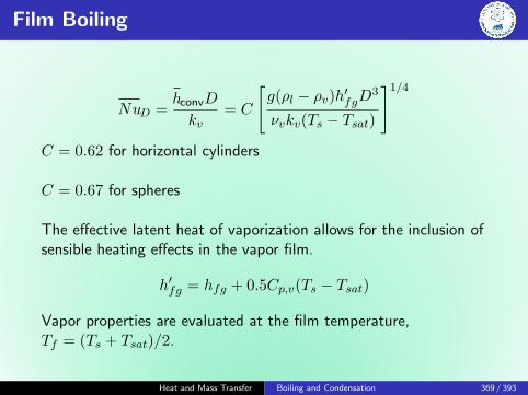
Film Boiling
NuD =hconvD
kv= C
[g(ρl − ρv)h′fgD3
νvkv(Ts − Tsat)
]1/4
C = 0.62 for horizontal cylinders
C = 0.67 for spheres
The effective latent heat of vaporization allows for the inclusion ofsensible heating effects in the vapor film.
h′fg = hfg + 0.5Cp,v(Ts − Tsat)
Vapor properties are evaluated at the film temperature,Tf = (Ts + Tsat)/2.
Heat and Mass Transfer Boiling and Condensation 369 / 393
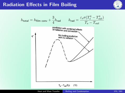
Radiation Effects in Film Boiling
htotal = hfilm conv +3
4hrad hrad =
εsσ(T 4s − T 4
sat)
Ts − Tsat
Heat and Mass Transfer Boiling and Condensation 370 / 393

Effect of Liquid Subcooling
Heat and Mass Transfer Boiling and Condensation 371 / 393
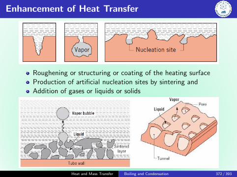
Enhancement of Heat Transfer
Roughening or structuring or coating of the heating surface
Production of artificial nucleation sites by sintering and
Addition of gases or liquids or solids
Heat and Mass Transfer Boiling and Condensation 372 / 393

Problem
The bottom of a copper pan, 0.3 m in diameter, is maintained at118◦C by an electric heater. Estimate the power required to boilwater in this pan. What is the evaporation rate? Estimate thecritical heat flux.
Saturated water, liquid at 100◦C:ρl = 1/vf = 957.9 kg/m3, Cp,l = Cp,g = 4.217 kJ/kg K,µl = µf = 279× 10−6 N s/m2,Prl = Prf = 1.76,hfg = 2257 kJ/kg, σ = 58.9× 10⁻³
Saturated water, vapor at 100◦C:ρv = 1/vg = 0.5955 kg/m3
Heat and Mass Transfer Boiling and Condensation 373 / 393

Solution
Saturated water, liquid at 100◦C:ρl = 1/vf = 957.9 kg/m3, Cp,l = Cp,g = 4.217 kJ/kg K,µl = µf = 279× 10−6 N s/m2,Prl = Prf = 1.76,hfg = 2257 kJ/kg, σ = 58.9× 10⁻³
Saturated water, vapor at 100◦C:ρv = 1/vg = 0.5955 kg/m3
Heat and Mass Transfer Boiling and Condensation 374 / 393

Solution
Saturated water, liquid at 100◦C:ρl = 1/vf = 957.9 kg/m3, Cp,l = Cp,g = 4.217 kJ/kg K,µl = µf = 279× 10−6 N s/m2,Prl = Prf = 1.76,hfg = 2257 kJ/kg, σ = 58.9× 10⁻³
Saturated water, vapor at 100◦C:ρv = 1/vg = 0.5955 kg/m3
q′′s = µlhfg
[g(ρl − ρv)
σ
]1/2( Cp,l∆TeCs,fhfg Prnl
)3
q′′s = 55.8 kW
mevap =qshfg
89 kg/h
Heat and Mass Transfer Boiling and Condensation 375 / 393

Solution
Saturated water, liquid at 100◦C:ρl = 1/vf = 957.9 kg/m3, Cp,l = Cp,g = 4.217 kJ/kg K,µl = µf = 279× 10−6 N s/m2,Prl = Prf = 1.76,hfg = 2257 kJ/kg, σ = 58.9× 10⁻³
Saturated water, vapor at 100◦C:ρv = 1/vg = 0.5955 kg/m3
q′′max = 0.149hfgρv
[g(ρl − ρv)
σ
]1/4
= 1.26 MW/m2
q′′min = Chfgρv
[gσ(ρl − ρv)(ρl + ρv)2
]1/4
Heat and Mass Transfer Boiling and Condensation 376 / 393

Condensation
Condensation is a process in which the removal of heat from asystem causes a vapor to convert into liquid.
Important role in nature:
Crucial component of the water cycleIndustry
The spectrum of flow processes associated with condensationon a solid surface is almost a mirror image of those involved inboiling.
Can also occur on a free surface of a liquid or even in a gas
Condensation processes are numerous, taking place in amultitude of situations.
Heat and Mass Transfer Boiling and Condensation 377 / 393

Condensation: Classification
1 Mode of condensation: homogeneous, dropwise, film or directcontact.
2 Conditions of the vapor: single-component, multicomponentwith all components condensable, multicomponent includingnon-condensable component(s), etc.
3 System geometry: plane surface, external, internal, etc.
There are overlaps among different classificationmethods.Classification based on mode of condensation is the mostuseful.
Heat and Mass Transfer Boiling and Condensation 378 / 393

Condensation: Classification
Heat and Mass Transfer Boiling and Condensation 379 / 393

Homogeneous Condensation
Can happen when vapor is sufficiently cooled < Tsat to inducedroplet nucleation.
It may be caused by:
Mixing of two vapor streams at different temperaturesRadiative cooling of vapor-noncondensable mixtures
Fog formation
Sudden depressurization of a vapor
Cloud formation - adiabatic expansion of warm, humid airmasses that rise and coolCloud - water or ice? -30◦C
Although homogeneous nucleation in pure vapors is possible,in practice dust, other particles act as droplet nucleationembryos
Heat and Mass Transfer Boiling and Condensation 380 / 393
Heterogeneous Condensation
Droplets form and grow on solid surfaces
Significant sub-cooling of vapor is required for condensationto start when the surface is smooth and dry.
The rate of generation of embryo droplets in heterogeneouscondensation can be modeled by using kinetic theory
Heterogeneous condensation leads to:
film condensationdropwise condensation
Heat and Mass Transfer Boiling and Condensation 381 / 393

Film vs Dropwise
Film condensation
The surface is blanketed bya liquid film of increasingthickness.
‘’Liquid wall” offersresistance.
Characteristic of clean,uncontaminated surfaces
Dropwise condensation
Surface is coated with asubstance that inhibitswetting
Drops form in cracks, pits,and cavities.
Typically, > 90% of thesurface is drops.
Droplets slide down at acertain size, clearing &exposing surface.
No resistance to heattransfer in dropwise. h is 10times higher than in film.
Heat and Mass Transfer Boiling and Condensation 382 / 393

Dropwise Condensation
Providing and maintaining the non-wetting surfacecharacteristics can be difficult.
The condensate liquid often gradually removes the promoters.
Furthermore, the accumulation of droplets on a surface caneventually lead to the formation of a liquid film.
It has been postulated that heat transfer occurs at the smallerdroplets due to higher thermal resistance in larger drops.
hdc = 51, 104 + 2044Tsat 22◦C < Tsat < 100◦C
= 255, 510 100◦C < Tsat
Heat and Mass Transfer Boiling and Condensation 383 / 393

Laminar Film Condensation
Heat and Mass Transfer Boiling and Condensation 384 / 393

Nusselt Integral Analysis
Assumptions:
1 Laminar flow and constant properties2 Gas is assumed to be pure vapor and at an uniform Tsat.
With no temperature gradient in the vapor,Heat transfer to the liquid-vapor interface can occur only bycondensation at the interface and not by conduction from thevapor
3 Shear stress at the liquid-vapor interface is negligible∂u/∂y|y=δ = 0
4 Momentum and energy transfer by advection in thecondensate film are assumed to be negligible.
Heat and Mass Transfer Boiling and Condensation 385 / 393

Nusselt Integral Analysis
∂2u
∂y2=
1
µl
dp
dx− X
µl
∂2u
∂y2=
g
µl(ρl − ρv)
u(0) = 0, ∂u/∂y|y=δ = 0
u(y) =g(ρl − ρv)δ2
µl
[y
δ− 1
2
(yδ
)2]
Mass flow rate per unit width,
Γ(x) =m(x)
b=
δ(x)∫0
ρlu(y)dy =gρl(ρl − ρv)δ3
3µl
Heat and Mass Transfer Boiling and Condensation 386 / 393

Nusselt Integral Analysis
dq = hfgdm
dq = q′′s (bdx)
q′′s =kl(Tsat − Ts)
δ
dΓ
dx=kl(Tsat − Ts)
hfg
δ(x) =
[4klµl(Tsat − TS)x
gρl(ρl − ρg)hfg
]1/4
Heat and Mass Transfer Boiling and Condensation 387 / 393

Nusselt Integral Analysis
δ(x) =
[4klµl(Tsat − TS)x
gρl(ρl − ρg)hfg
]1/4
The thermal advection effects may be accounted by:
h′fg = hfg(1 + 0.68Ja) Ja =Cp∆T
hfg
q′′x = hx(Tsat − Ts)
hx =klδ
=
[gρl(ρl − rhov)k3
l h′fg
4µl(Tsat − Ts)x
]1/4
∵ hx ∝ x−1/4
hL =1
L
L∫0
hxdx =4
3hL = 0.943
[gρl(ρl − rhov)k3
l h′fg
4µl(Tsat − Ts)L
]1/4
Heat and Mass Transfer Boiling and Condensation 388 / 393

Nusselt Integral Analysis
NuL =hLL
kl=
[gρl(ρl − rhov)L3h′fg
4µlkl(Tsat − Ts)
]1/4
The total heat transfer to the surface may be obtaned by:
q = hLA(Tsat − Ts)
m =q
h′fg=hLA(Tsat − Ts)
h′fg
Heat and Mass Transfer Boiling and Condensation 389 / 393

Turbulent Film Condensation
Reδ ≡4Γ
µlCondensate mass flow rate, m = ρlumbδ,
Reδ ≡4m
µlb=
4ρlumδ
µl
Heat and Mass Transfer Boiling and Condensation 390 / 393

Turbulent Film Condensation
Heat and Mass Transfer Boiling and Condensation 391 / 393

Film Condensation on Radial Systems
Heat and Mass Transfer Boiling and Condensation 392 / 393

Film Condensation on Radial Systems
NuD =hDD
kl= C
[ρlg(ρl − ρv)h′fgD3
µlkl(Tsat − Ts
]1/4
C = 0.826 for sphere and 0.729 for the tube.
For N horizontal unfineed tubes, the average coeff.:
hD,N = hDNn
n = −14
Heat and Mass Transfer Boiling and Condensation 393 / 393


![[Solutions Manual] Fundamental Os Heat and Mass Transfer [Frank p. Incropera - David p.dewitt]](https://img.dokumen.tips/doc/110x75/55720f17497959fc0b8c8a2b/solutions-manual-fundamental-os-heat-and-mass-transfer-frank-p-incropera-david-pdewitt.jpg)