Embed Size (px)
Citation preview

A-A131 844 TH STUDY OF 4 I FLMSON SMI-NSULATING GALLIM
ARSENIDE BY ELPSOMETR U) AI BFORCE WRIGHTAERONAUTCA A ABS WRIGHT-PATE SON AFB OR-
UNeLASSIFIED N I MCDEAITT E AL. UN 83 AFWAL R-83 4034 F/G 14/2 NLiilllllEIIIIIIIIIIIIlIIIIIIIIIU

..... , l11..8 1.251
-211 1111 .
2.0
MICROCOPY RESO' FUON TEST CHANT
1*

AFWAL-TR-83-4034
Si
THE STUDY OF THIN FILMS ON SEMI-INSULATING GALLIUMARSENIDE BY ELLIPSOMETRY
Neil T. McDevittWilliam L. Baun
Mechanics and Surface Interactions BranchNonmetallic Materials Division
June 1983
Final Report for Period January 1982 to December 1982
-I
Approved for public release; distribution unlimited.
Uj
MATERIALS LABORATORY
C.2 AIR FORCE WRIGHT AERONAUTICAL LABORATORIES
j AERONAUTICAL SYSTEMS DIVISIONWRIGHT-PATTERSON AFB, OHIO 45433
•8 0 26 ....

rNOTICE
When Government drawings, specifications, or other data are used for any purposeother than in connection with a definitely related Government procurement operation,the United States Government thereby incurs no res, nsibility nor any obligationwhatsoever; and the fact that the government may have formulated, furnished, or inany way supplied the said drawings, specifications, or other data, is not to be re-garded by implication or otherwise as in any manner licensing the holder or anyother person or corporation, or conveying any rights or permission to manufactureuse, or sell any patented invention that may in any way be related thereto.
This revort has been reviewed by the Office of Public Affairs (ASD/PA) and isreleasable to the National Technical Information Service (NTIS). At NTIS, it willbe available to the general public, including foreign nations.
This technical report has been reviewed and is approved for publication.
4 1IL T. MCDEVITT STEPHEN W. TSAI, ChiefMaterials Research Engineer Mechanics and Surface Interactions Branch
Mechanics & Surface Interactions Branch Nonmetallic Materials Division
FOR THE COMMANDER
FRANKLIN D. CHERRY ChiefNonmetallic Materi s Division
"if your address has changed, if you wish to be removed from our mailing list, orif the addressee is no longer employed by your organization please notify AFWAL/MLBM,W-PAFB, OH 45433 to help us maintain a current mailing list".
Copies of this report should not be returned unless return is required by securityconsiderations, contractual obligations, or notice on a specific document.

UNCLASSI FIEDSECURITY CLASSIFICATION OF THIS PAGE (Whe DatetEntorfd)_
REPORT DOCUMENTATION PAGE RFAD iOMRU(TI(IFRt REPORT NUMBER 2 GOVT ACCESSION NO. 3 RECIPIENT'S CATALOG NUMBER
AFWAL-TR-83-4034 TP
4. TITLE andS.bIle) S TYPE OF REPORT & PERIO) COVERE-D
THE STUDY OF THIN FILMS ON SEMI-INSULATING InternalGALLIUM ARSENIDE BY ELLIPSOMETRY Jan 82 to Dec 82
6 PERFORMING 01G. REPORT NUMBER
7. AUTHOR(s) 8 CONTRACT OR GRANT NUMBER,)
Neil T. McDevitt and William L. Baun In-House Report
9 PERFORMING ORGANIZATION NAME AND ADDRESS 10 PROGRAM ELEMENT. PROJECT. TASK
AREA & WORK UNIT NUMBERS
Materials Laboratory Project 2303Air Force Systems Command Task 2303Q108 WID #50Wright-Patterson AFB, Ohio 45433II. CONTROLLING OFFICE NAME AND ADDRESS 12. REPORT DATE
Air Force Wright Aeronautical Laboratories June 1983Materials Laboratory (AFWAL/MLBM) 13 NUMBER OF PAGES
Wright-Patterson AFB, Ohio 45433 3414 MONITORING AGENCY NAME & ADDRESSOI difflerentf (in, C- roIing Off1ce) 15. SECURITY CLASS. (ol th-s re f)
UnclassifiedI5a DECL ASSIFICATION DOJ"R A 'IN
SCHEDULE
16. DISTRIBUTION STATEMENT (,i FhIs Report)
Approved for public release; distribution unlimited.
17. DISTRIBUTION STATEMENT ,,-I the ahstra t entered in Rh k 20, if difierent fron Report)
18 SUPPLEMENTARY NOTES
19 KEY WORDS (Continue on re.erse side if necessary and idenrifY hy blnck numb..)
Ellipsometry Gallium Arsenide Dielectric Films Epitaxial Films
Metal Films
20 ABSTRACT (Conllnue an reverxe side If necessary and Idetfvt•
ht- b,r'k uamher)
A computer-grid procedure is discussed where delta and psi values obtained froma thin filmed surface are used to estimate the optical constants of the film-free surface. Thin films can be measured with reasonable accuracy on galliumarsenide; however, the optical constants of these films cannot be obtained.
DD I jAN 7 1473 EDITION OF 1 NOV 6S IS OBSOLETE UNCLASSIFIEDSECURITY CLASSIFICATION OF THIS PAGE ,hen t1st K,,Iepe

AFWAL-TR-83-4034
FOREWORD
This technical report was prepared by N. T. McDevitt and W. L. Baun
of the Mechanics and Surface Interactions Branch, Nonmetallic Materials
Division, Materials Laboratory, Air Force Wright Aeronautical
Laboratories. The work was initiated under Project 2303, "Surface
Phenomena" and WUD #50, "Surface and Interface Properties," monitored by
Dr. T. W. Haas.
This report covers work performed in-house during the period January
1982 to December 1982.
The authors are grateful to Mr. Gary Griffin for his technical
assistance with the computer program. p
II
ii..
ic es~cnFor
2tetribation/Availabillty godes
Lo lAwa±1 amd/orDil
Di* rea

AtWAL-IK-83-4US4
TABLE OF CONTENTS
SECTION PAGE
I INTRODUCTION 1
II EXPERIMENTAL 4
III PROCEDURE 5
IV RESULTS 7
1. Dielectric Films 7
2. Epitaxial Films 12
3. Metal Films 22
V DISCUSSION AND SUMMARY 27
REFERENCES 28
V,
AFWAL-TR-83-4034
LIST OF ILLUSTRATIONS
FIGURE PAGE
1 Reflection of Polarized Light into its OrthogonalComponents
2 Computed Delta and Psi Relation for Various ComplexRefractive Index Values of GaAs at Zero Film Thickness 8
3 Computed Delta and Thickness Relation for VariousRefractive Index Values of Ga203 on GaAs 10
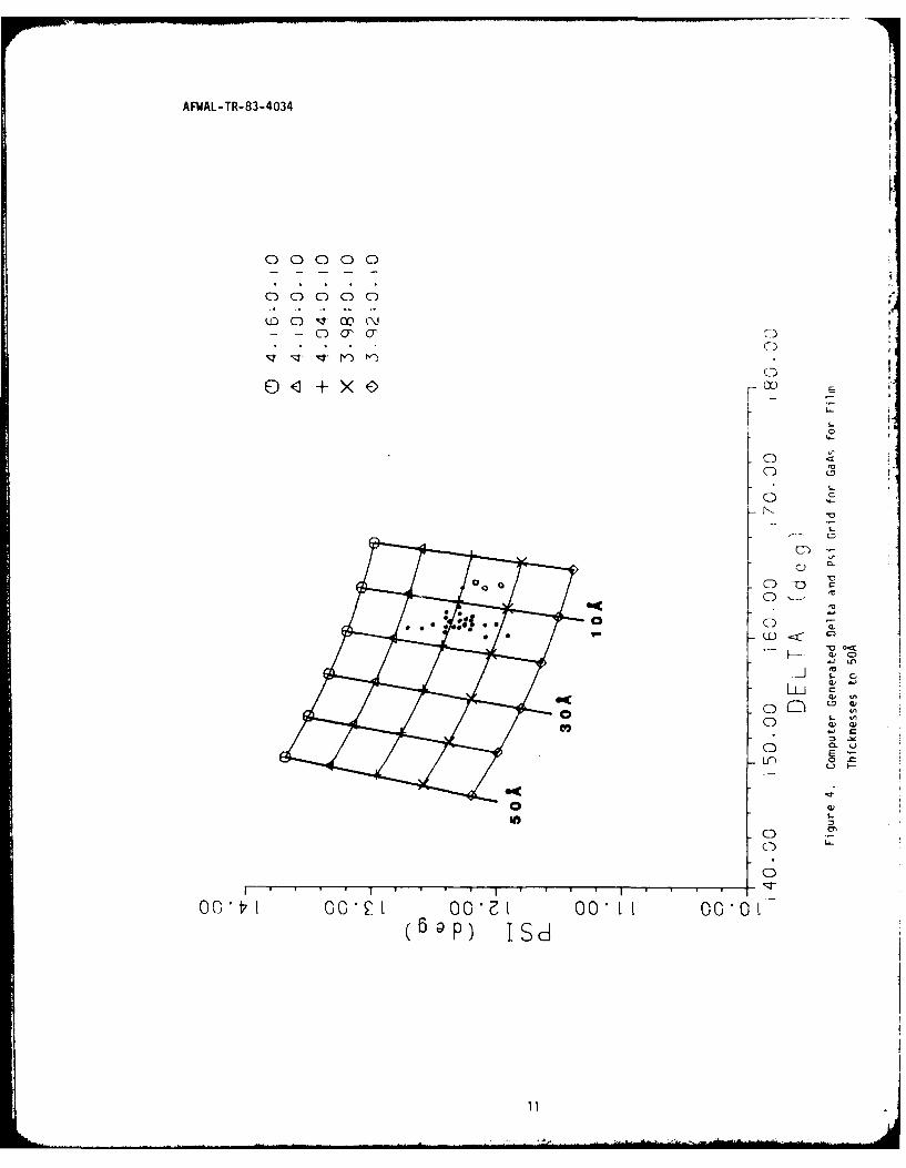
4 Computer Generated Delta and Psi Grid for GaAs for Film
Thicknesses to 50A 11
5 Computer Generated Delta and Psi Relation for a Ga20 3Film Having an Imaginary Part 13
Relationship of Delta and Psi for Films of Varying o
Refractive Index on GaAs for Thicknesses up to 2400A 14
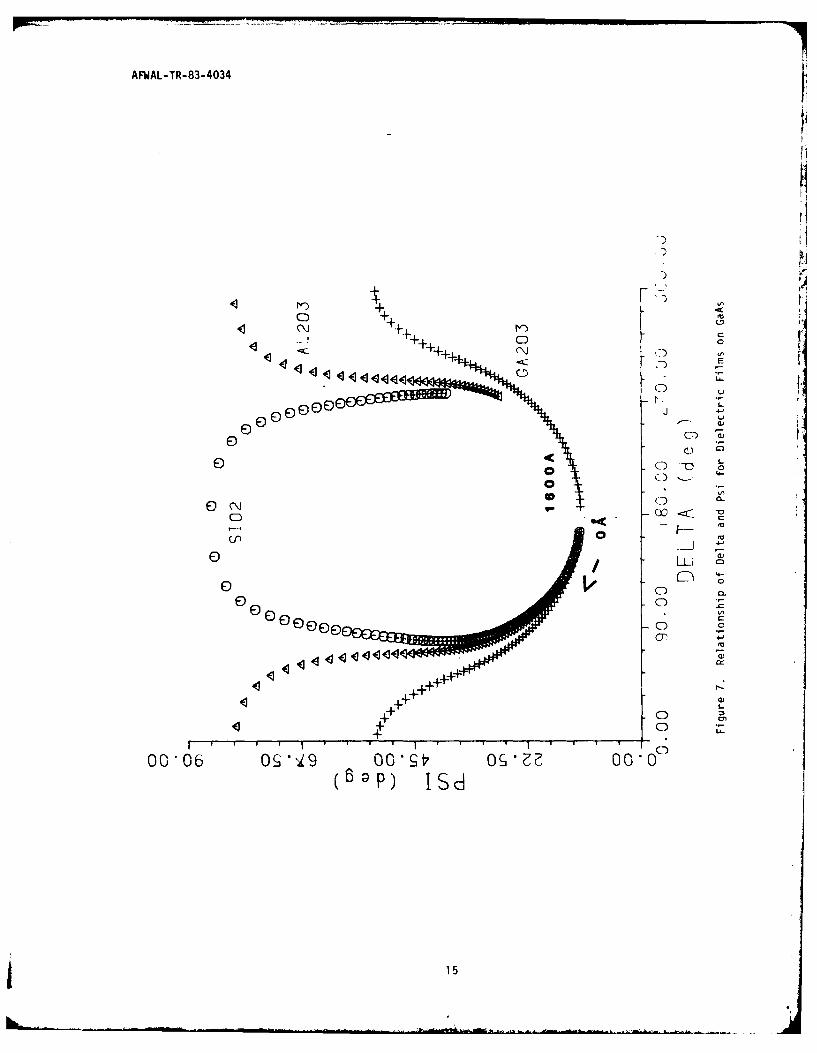
7 Relationship of Delta and Psi for Dielectric Filmson GaAs 15
8 Relationship of Delta and Thickness for a Closed Curveof Ga203 on GaAs 21
9 Computed Delta and Psi Relation for Epitaxial Film GaAlAs
on GaAs for a Thickness of 2500 23
10 Relationship of Delta and Thickness Showing a DampenedCurve for GaAlAs 24
11 Relationship of Delta and Psi for Metal Films on GaAs for
a Thickness of 400 25
12 Computed Delta and Thickness Relationship for Metal Films Ni,Ge, and Au 26
vi
AFWAL-TR-83-4034
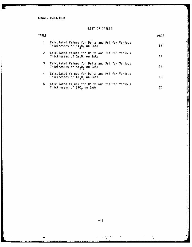
LIST OF TABLES
TABLE PAGE
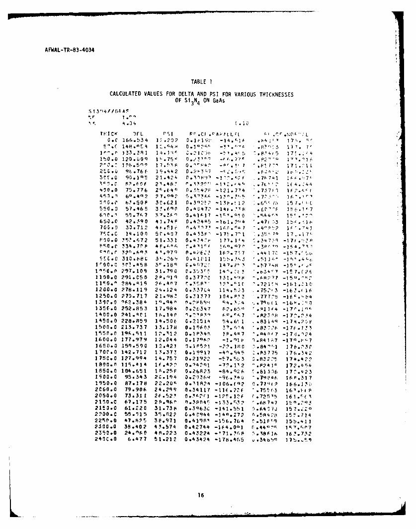
1 Calculated Values for Delta and Psi for VariousThicknesses of Si3N4 on GaAs 16
2 Calculated Values for Delta and Psi for VariousThicknesses of Ga203 on GaAs 17
3 Calculated Values for Delta and Psi for VariousThicknesses of As203 on GaAs 18
4 Calculated Values for Delta and Psi for VariousThicknesses of Al203 on GaAs 19
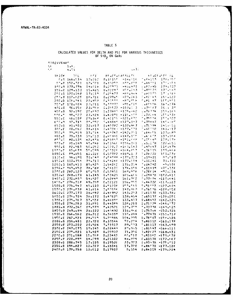
5 Calculated Values for Delta and Psi for VariousThicknesses of SiO2 on GaAs 20
vii

AFWAL-TR-83-4034
SECTION I
INTRODUCTION
Optical methods have for a long time been extensively employed in
surface studies and one of the more sensitive techniques used in this
field is ellipsometry. Ellipsometry is virtually the only method for
the direct determination of the optical constants of a large number of
materials, and for the detection and quantitative thickness measurement
of films deposited on these materials. The mathematical equations used
in ellipsometry were formulated at the end of the last century; however,
due to the ct:iAbersome trigonometric equations involved in the analyses
of these data, the technique, through the use of computers, has only
been utilized in the last decade. This particular study was mainly
accomplished through the use of McCrackin's (Reference 1) computer
program for ellipsometry.
In principle, ellipsometry involves directing a monochromatic beam
of linearly polarized light, at oblique incidence, onto a clean, flat
reflecting surface and analyzing the state of polarization of the
reflected beam. We can be a little more specific by referring to Figure
1. The plane polarized light has been rotated into s and p components,
where the s component vibrates perpendicular to the plane of incidence
and the p component parallel to it. The interaction of this light beam
with a surface is unique and computation of the differing phase and
amplitude of the orthogonal components enables the optical constants of
a material to be determined. However, the application of
electromagnetic theory to the reflection of light from materials
containing free electrons requires the use of a complex refractive
index. The free electrons cause an absorption of the incident light and
the complex portion of the refractive index is justified by the fact
that the imaginary part permits an easier solution to the absorption
problem. The complex refractive index n is usually written A = n-ik.
Both n and k are positive numbers with the negative sign an arbitrary
choice for the direction of propagation of the electromagnetic wave.
1"
_ _ _ _ __.. . . . ... .• .. . . . . ... . . . .. . . .. .. . .. ... . . ,

AFWAL-TR-83-4034
f
'I,
4-,
a,00.
04-)
#0
0
C
4)4-
0
4-'
04)C
4)
-J
a,N
S.-'U
0a-I'-0
C0
4)UU)
'4-a,
a,I-
0,
Li-
2

AFWAL-TR-83-4034
Interaction of light with this same surface when it is covered with
a continuous, transparent (to the wavelength of light used) isotropic
film is also unique, and often allows for the determination of the
thickness of the film or its refractive index. In the case of a non-
absorbing film or substate, k will be zero and the film or substrates
optical constant will be designated only by n.
Our interest in ellipsometry is aimed at the study of thin films on
semiconductors, in particular gallium arsenide (GaAs). Ellipsometry
appears quite suitable for the study of these films for several reasons:
(1) it is nondestructive by nature; (2) it can be utilized at ambient
conditions; and (3) substrates can be studied under realistic processing
procedures.
Thin films on semiconducting or semi-insulating GaAs are essential
in device and circuit fabrication, particularly in FET (Field Effect
Transistors) devices. These films help establish the appropriate
properties of the GaAs surface for fabrication purposes. The
determination of whether the GaAs surface is clean or contains a film,
and the thickness of the film, is an important aspect of this
technology. The main emphasis of this report will be on the optical
characteristics of the <100> surface of the GaAs and the affects
dielectrics and metal overlayers have on these properties.
3

AFWAL-TR-83-4034
SECTION II
EXPERIMENTAL
A Rudolph ellipsometer (Model 43702) was used for this study. The
experimental details are described in a previous report (Reference 2).
A mercury light source was used (546.1nm) and all measurements were
performed at an angle of incidence of 70'. Extinction points were
obtained from the polarizer and analyzer settings in Zones 1 and 3. All
computations were performed on a PRIME 550+ computer. The program is
capablc o7 performing nine different ellipsometric computations. Our
main use of the program in this study was centered on the computation of
delta and psi for the purpose of studying the refractive index and film
thickness of semiconductor materials.
All of the semi-insulating GaAs wafers used in this study were
obtained commercially. The wafers were cut from boules grown by the
liquid encapsulated Czochralski process. The polished wafers are 50mm
in diameter, 0.5mm thick, and are oriented on the <100> plane. No dopants
were added intentionally.
4

AFWAL-TR-83-4034
SECTION III
PROCEDURE
It is necessary to have access to a computer to facilitate the
computation of the ellipsometric data. Also it must be remembered that
the foundation of ellipsometry is buried deeply in theoretical models.
These models require the surface of the substrate to be optically smooth
and film free to obtain a true refractive index. The film must be
optically isotropic, homogeneous, and transparent to the wavelength of
the light source. The light source has to be monochromatic. Other
problems that may arise, such as precision of measurement or instrumental
errors, can be found in the literature (References 3-6). Consequently,
data acquisition from real surfaces still leaves the interpretation
aspect of the computed data fairly subjective.
In this report we will be dealing primarily with the ellipsometric
parameters delta and psi and their dependence on the values of the
refractive index of the substrate (ns ), the imaginary part (k ), andS S
the thickness (d) of the film. All of these are referenced to an angle
of incidence of 70' and 546.1nm incident light. As mentioned previously,
the complex refractive index is written
n = n - ik (1
where k is usually referred to as the extinction coefficient. However.s
the input into the computer program we are using will not take the value
of the extinction coefficient (k ), rather it requires the parameterS * *
called the absorption coefficient (k s). ks is related to ks by the
following:
* ks (2)s n5
the complex refractive index may then be written as
ns = n s(l-ikS) (3
Hereafter, this report will always use ks when referring to the imaginarypart of the refractive index.
5

AFWAL-TR-83-4034
Ellipsometry is noted for its sensitivity to changes in the surface
of materials. The sensitivity of the technique can be estimated from
the following equation that defines the penetration depth of the light as
d - * (4)P 4,n k
s s
the distance of penetration into the material which is measured in a
direction normal to the surface and is dependent on the product of n ks s
For light of 5461, and several values obtained from the literature for
n and k for gallium arsenide, the calculated penetration depth will beS S0between 800 and lO00A.
6

AFWAL-TR-83-4034
SECTION IV
RESULTS
1. DIELECTRIC FILMS
Ellipsometric measurements were per' rmed on five semi-insulating
gallium arsenide wafers. These wafers were cut from the same boule.
Delta and psi values were obtained from five areas on each two inch
wafer. These experimental data points are plotted (solid dots) on the
graph (Figure 2). The grid shown in Figure 2 was computer generated. It
was formed by using a series of n and k* values for gallium arsenide
which were obtained from the literature. Each intersection on the grid
represents a delta-psi value that would be obtained from a film-free
surface (d=o). The spread of the data points is small and indicates the
surfaces of the wafers are optically homogeneous. Because of the small
spread in the data we can see from the graph that a reasonable average
value for these points would be ns = 3.98(l-iO.14). However. every
gallium arsenide wafer, under ambient conditions, will have a film on the
surface. The refractive index obtained from the graph will then be an
apparent refractive index and not represent a film-free surface. In
order to accurately obtain the thickness of a film on a surface the
refractive index of the film-free surface must be known with some
accuracy. This usually requires the measurement of the optical constants
of a film-free surface while in an ultra-high vacuum environment. Other
difficulties involved in this type of measurement are the possible
damage to the surface while removing the ambient film while under vacuum,
and the presence of the windows of the chamber between the light source,
sample, and detector.
The following ellipsometric method is proposed as an easy and quick
determination, under ambient conditions, to obtain the optical constants
of a film-free surface. However, we are not proposing that this method
is capable of predicting the absolute value of a film-free surface, but
only a method to obtain the refractive index of a reasonably film-free
surface of a particular substrate being studied.
7

AFWdAL-TR-83-4034
0
0~
C)
0
C)
0
140.00 150.00 160.00 170-00 180.00
DELTA (deg)Figure 2. Computed Delta and Psi Relation for Various Complex Refractive
Ir~dex Values of GaAs at Zero Film Thickness
1:8
AFWAL-TR-83-4034
It has been shown empirically that a nonabsorbing film on an absorbing
substrate will lower the value of the real part of the refractive index
while increasing the value of the imaginary part. Taking this into
consideration and knowing that the data in Figure 2 represents a film
covered surface, we can obtain the optical constant of a surface with a
thinner film by moving to the right on the grid in Figure 2. Arbitrarily,
we chose the next intersection on the grid and read ns = 4.04(I-iO.I).
We can now generate another set of curves in the following manner. Since
ks is very small compared to ns, delta and psi values will be insensitive
to small changes in k s . Curves may then be obtained by varying the real
part of the refractive index, 4.04+3%, and keeping the imaginary part (0.1)
constant. The film growth will be 0 to 50A with a refractive index,
nf = 1.90. With a film of this thickness the refractive index can vary
by +5% and no error will be introduced into the readings (Figure 3).
From the above data a second grid can be constructed as shown in Figure 4.
Plotting the experimental data on this graph (solid points) show the GaAs
wafers to have a film approximately 15A thick with the optical constants
for the film-free surface being 4.04(1-i0.l). Further indications show
in Figure 4 that we have a reasonable value for ns which can be seen by
the position of the open dots. These data points represent delta-psi
values for several of the wafers after they have been chemically etched.
The points indicate that some of the original surface film has been
removed. These same wafers were subjected to a study by X-ray photoelectron
spectroscopy and the corrected cross sections for the Is line of oxygen
and the Auger LMM line of gallium indicating only a small amount of oxygen
is present on the surface.
By this comparison between the experimental data points and the
calculated delta-psi grid diagrams, formed by varying the real part of
the refractive index (4.04+3%) for a 50A film, we have demonstrated a
method that should reveal the optical constants of a film-free substrate
that are within the experimental error range of the unique value. The
rest of the film data presented in this report will be referenced to the
substrate optical constant obtained from Figure 4 where ns = 4.04(1-i0.1).
The assumption that the GaAs surface has a continuous film under ambient
g

AF'AL-TR-83-4034
000C) C
LL L_ 0z z Z 0
041
4LC,
0C,.) - Int
~C)>
to
0 x0 _
4--
0
O2 ,. En
S ' ' ' I T I I I I "T I-
00 081 00 09 0o o 0 0o o z 00 06 0o 0 9 C( p) v J. 7
10
AFWAL-TR-83-4034
C) 0 0 0 0
0 00 0 CT.)f
0
C)
o +X, r a
LO
o C)
LLn
-J
CF) T .3
c)
C
p) I sd
V 011 . .,
C.

AFWAL-TR-83-4034
conditions seems valid when compared to the work (Reference 7) reported
on GaAs at reduced pressures of oxygen where coverage is obtained around
three monolayers. The stoichiometry of the film may be As203, Ga203 or
GaAsO 4 but when dealing with a thin film these differences are not crucial
(Figure 3) to this procedure. We also assumed that kf = 0, however, the
film may be slightly absorbing and the variations of delta and psi for
thin films will not be large enough (Figure 5) to make this procedure
invalid.
When a value has been established for a particular surface then
delta and psi curves may be calculated for thicker films. Figure 6 shows
the effect the refractive index of various films will have on the
substrate being studied. A film with an index of 2.50 on this substrate
will lose its sensitivity with the psi parameter and will require a fit
primarily with the delta parameter. These curves were calculated using
= 4.04(1-i0.1), keeping the real part of the film refractive index
constant and kf = 0, while varying the thickness of the film. Figure 7
shows a similar series of curves for films that are commonly used or
found on GaAs. The film was calculated for a film of 1600A. Values for
these films and several others are presented in Tables 1-5. The delta
and psi values will repeat themselves after an increment of one wavelength
of the light source used. This type of curve is considered closed.
Comparison of delta with film thickness for a system of Ga203 on GaAs is
shown in Figure 8. This figure shows the repeat pattern of a closed
curve.
2. EPITAXIAL FILMS
Ternary and quaternary compounds are becoming increasingly important
as CVD films on GaAs. Problems that are usually encountered in this type
of film growth i -e lattice mismatch and dislocations. The use of
ellipsometry in connection with vapor-phase film growth has been studied
(Reference 8). Most of these films will have some free electron character,.
thus kf t 0. When films become slightly absorbing the effect of the
substrate on the reflected light becomes less pronounced as the film
becomes thicker. The delta and psi curves will no longer be closed
12

AFWAL-TR-83-4034
0 L 000-0
0 1 00 0.000o
C5
0
f-b L-Ln
1C
0
tjI.-
0J
(B~p) ) d
" 0i

AFWAL-TR-83-4034
LO 0 0\j tr" tr
LLA_ l L. C)
0 C)DCA
W
I.
4J
L
4+-
in
+ C)
CapC+
+U
Ll
0
C;
0 2o0) L*0
1.
o o.
co uc a
I I
(Bap) IIA
14)
AFWAL-TR-83-4034
E))
E)E
._!' 0
4-,i
0000 0 1
00 7,---
0 c- i9 I
. " a) L--0 e, "" 0 < 0o ", _
o- o f--
00
o
000 +++++++
(6)p 0
15)
AFWAL-TR-83-4034
TABLE 1
CALCULATED VALUES FOR DELTA AND PSI FOR VARIOUS THICKNESSESOF Si3 N4 ON GaAs
S 131'4//Ga A.F
TE I CK 3FL rI F r CF v Ak tLL -I - M rG.o 166.534 1;. 292 e 0. '; -. .1 '- . ,'I 17t,.
]"r7 e ]313.38 1 .1 1 ~ ' r Z,. 1L "it- -,"!o4' 5 -,o8 4 5 17',..-4
15 0.0 120.U09 1'.75W 0.23'r- -. 7Yr .I nto 5n 1 7r P OoIr* -or* ' - 0or 1 * 17 . 1 1
25.C D q6 . 76- 1 r .44 2 0 . P 2 3 7 -c i. -; " F- ;2 ' '.' r, " ,3f.f .0 90.IQ5 21.42" 0.I197 -1' I .k; F .7P741 f-. ;7Ll;!. 8.6nf 23.46! - I12. i4 .7t2 If 4. 44'490.0 75.776 2;.E.4c 0*.4,2 P -121.774 .737) 3 1 2.'. I
5 1 .00, 6,. 50 I 3C.E21 C *3 q ,. -131-.1l 1 - .6r- ,: 5 =7. ' C
550*0 57,*465 3!.fn0 .0, 4 7.1 - 14t E . , 601-F ]3 o 761P.1 Slo.7 7 "r. ! -
n 13. 1 c17 . ' ,0 . 44,r-x I~ , .c
650.0 42.3q 0 41]74P 0*424m5 -lbl.2"4 .471 .3 Ib,'.II,700 o 3a. 712 46.51 r 1) n -.4 1,M 7 r - . 4, P'.p 2 1F ". 1,7". C . C 14#10O0 5 r . 407 0.4 33F" -17,= 7' 1 &+ 3 +;" 17 .1 7 L
1',0.0 35?. 672 51.331 0. 4347r 177. 1'4 S.34 7 "q -17 .'P.0=',t 34#7r P 4Fo.A1 '" C6.a1rs !. ,*oQT, *3Pr.7n -1.'7oV.
12*00.0 78.1VP 4.128A 0. 47 1 4 rc3 !.37,n3 -163. 1 4
I mc, o.P 297.109) 31.790 V . 3 r:3rr "7 14"'. t 3 " 3 4c7 -1 !7. 1 2,
1 100 0 2 91 .C 50 2 P ." Iq 0*377 C 13 1 . -'jp F OR,9P 7 -15 Q. ^ ,
1200,0 278.119 24*,1214 0 . 337 114 !; i3 .75.13 -163. 16
1250.0 270.717 21.983 C921377 104P! ! "777 t -1F. t4
135C.0 252.853 17.984 0.26347 1p2o650 r%.1'4 -17fo.Vn1400.0 241. V 1 1{",.14r p ' (,°.",7 . A2 F",l -17-^.:34145090 228.859 14.50t 0.21514 54.6' 1 .. 8314q -174.2'41500.0 213.737 13.178 0.176fP3 37.f 4 ".837, - -17f.1!3Ir)5P* 19co. 11 1 ° 1 OoAl2 0 l1P14!1
, IP .4 Q7 . An t.7 -176. 124
1600.0 177.979 12.044 0017lf, -. 1 "%o.41k7 -17c .1-71 65ti. 0 15q.590 12.421 le 1P 5P1 -. 1 I % 84 "' , 17 [..23 r1700.0 142.712 1 .37! 0*19917 -4 o4 Z.P37 75 176.342175Co0 127.994 14.757 0.21922 -,7.SL3 0.8322. 174.4221800.0 115.a14 1 f,. U. n 0.?4?1 -77.1'Y2 %P241r 172.t 4.1850.0 104.651 1 A.25F 0.26 823 -84 .6 f-.81 336 17,4 231500.0 95.343 26.194 3.293(,1 -96,..a 3 " 79,14 16P.3171950.0 87.178 22*20
r, 001A?'. -106.iQ2 0.77q(P 166.15b
200.0 79.906 24.299 0*34111 -IIf .*2 f .755.3 16' 1 f2050.0 73.31 I 2f.527 .cprj -1p5 12F C.72.1I 16 1." I2110.C 67*175 2Po96fn l)3P(14r .1 33,r3P 2 o68747 1It o:lq 2
21O.O 61o220 3 1.738 0t3963C - 14 1*b)1 C.641 3-J 157. 2 o
2700,C 55.15 35,n22 G.4 4.944 -14O.272 .5P4 ;'If 15, 5.72 24226P .0 47. o 6Pw 3P.971 0o 4 19P", -156.064 r *51 F r.9 15t.4112300.0 38.402 4 3.574 0.42744 -164,0o1 O I -4 Q " I C; r, 72350.0 24 . nt, 0 4S.223 0.43224 -1 71. 3rP ,38 A] h 1,K.732249C.0 6.477 51.212 0.43424 -178.o4G5 w.3465n 1 7b..c ,
16

AFWAL-TR-83-4034
TABLE 2
CALCULATED VALUES FOR DELTA AND PSI FOR VARIOUS THICKNESSESOF Ga203 ON GaAs
3;A2( 3/G AS
r Q o1
T H ICK FL 11F] F r r f IA. tLr r, t 1. L Ir t 'L
C C 161;. 5 !4 1:. 3 1.:l' -A.1, .:t, ." : .
5,.r 14".r,)7 I.o O' C. I- C.7 - 4'. ,'4 .b. 7c 17' -'
V 1' l nb 14.202 0.'11.7 1 ... , ' 17 4"
15r.0 120.227 1t.o7 5 0 ' _L r, * '4 Z f - c.C. ,-2,n , .V 1P.P rn 3 1 7. !,7F 6 ° 42 1 7 - n7'1 , I1 1 7 1.'
2'5C. 0 Q9.19q7 1 ?.4(17 0 .21.'5L4 IC I- .f ,, ItL
?
3P0.0 Q00742 21.47' C .310!_ -101. ' 7 .7, If lt 73' !; P ".57 P 2 .r 0 .7 41 -112 '. '9 .7t If4. 424 fD . 0 76*5P8 2 2 83 .3b6 3r' -1 1. 1,1 .74 '2 . 164 0., 0 47 41.5 '17 D.3 -, -" Z .' n .7. P 2 1t3.7 i" p .C 0 949. 3 ko fU3 52.3 °; 3 3 , ' -137°.7; 7 6c .- , 4 F''52.0 532. 5 316.17 0.4^1 ' 14". ' 2 .4.1 ', 2 -I. ,vn oo 51°7111 77o. 4 1o -1 ^ 71
'o Q = 4 l = :.
65 O 45.721 105t7 045 0. r4 1 1 .. 5 i 47 04-2t) I04 -- 6-
7120 0 3470f 45 .17 .040t ' -!(,7. :7 .41 16 'c
12r5.0 18.P 2.96 . 0. 4 4 1n7 . 0' F -.4 i I 1 -4 3 9 I,C 0 . C T"5-8 o 4 ". 52.P24 r . 4'40 C 1 7,A. 774 . 3 . c -17" , -
n " 38 1P1 5 7. 0 7 . 747 . 38 1 -lF(. l
! ?.0 22.6. 1 46o17f 0.4 332 1 4.7 12 .41! 17 -15 ',.I2C.r 312.359 41.203 0.42614 1 7 .,F .',)+rP 72 -154. ^,4
lr 0C 0 304.729 3 .829 0.416CC 14Po2!1 "o5-'. 4 -1 4. 1-
1 50.0 298.452 33.194 0.4C31 .3 120. ?1 .fI, 1. . -1 '7 ,I11C0.0 282.622 30.Irr 0.-0'757 I't 4.A4 F F6"11 -1; 7. 7411c.0 1 o7P0 2 7o 53 0.'!#41 1 2( 6. 1 .7r ( 7 -16 . (12OP.0 280.427 25.176 0.24E82 11-..,bP " .74.-9 -167 1'12 r,. 0 273 .50 P 22o9bt r, 3 26 6P IC: 7 0 P o 7-P :.76'- 1-9 -1(-4.741.
1300.0 -c*74 a 20.901 0 1.22IIr' .74 '7 .78 71 -167. 3135C.0 256.912 2P.3P9 0.27"6El F7.7140 :o62 164.'&51 i 4 r. ;) 4 f.7n 0 16 .nn 4 ftPP Il 24 7 .44 1 F IP F') -1 7 1. 9
'
15r .rP 34.757 15. 2 2 0.22576 tI ] 4F4 ".127 1 -17 3. 141 CC .- 22PP .728 13. 743 0.2 14.^4 4.4P 83' r P -17 5 . 3 1I2r. 04.471 1 .4n a 0. It -12.32r "P,!'-44 -177.14C2300. 0 186.424 12 ,VS2 4 0.1-03 7 7. 2.'0 '.64 1 P -170. '3t15 U5 o f' 167.Ql 3 12.172 0 .I -1 rl3. ] * I41 I 1 17 .17 .ro0 150.14 12o885 0.o-2.14 -7.7(.!7 .63-12 177.15,175 0 o C, 134. I f, 14.102 Co2f E2 - . 2C-7 Z. 63' 1 17 c . !' 71 7
11 r 1 1 "P 067 P*" 1 22 ! , " " 3p l 171.121
IP,50n 19.647 17.447 0.25742 -75o [145 C o31' , b 17 1, 0
19L.0 . 0 q . 8 31 19o351 1.29324 -0f2.c4f .nO I , !6 C, Y
I q5 r. 0 91*297 21.334 0 *3 3fiW -lI CI o 4 r .7r 15 167.. 5tb
2CC C.O 83.772 23.381 0 *33 2(,( -111. 42 " .7(-' 26 16 4 . G
2CbOoO 77 9 03 4 2 " o 4 0O r 4 P4 -17.'.4" 1 F.74 7 m 1 11 . ?75
2 1 nf- r.,' 7noPP3 27041 no3747(- -IPc oP' I i o79"-L7 16 ' 1I(
2153.C 6)5.G96 3C~o4lC 0*3c'220 -137.077 - °6ot-21 lbT.!L '7
220C .C 59o364 3 .38q 0*4 f'1 -144.PI 3 -o61713 15 -. '2 !
22P Oof v)!.179 3 f. ,!37 3*41912 - I ^. 2P E o 55 , b 15 4. '3 t2306*0 45o651 41.250 no.^84q -15o.560 03.44 f'47 154.7kF
2350.A 35o27P 46916? 0*435 ' -16A.6SI "o417FT 15P.^?F24CO90 20o114 53.713 0.4Zb0'4 -173,7, 7 " ,C.= I 16Ao.15f
17

AFWAL-TR-83-4034
TABLE 3
CALCULATED VALUES FOR DELTA AND PSI FOR VARIOUS THICKNESSES
OF As203 ON GaAsA' 2n3IIGlS ?
RF 1 op1
F 4 .04 .,]
THICK 3FL rs R- .(F . A;ALLrL L . 4cv *V :L0.C 166.'34 1:.2J 0.1 '1 -14.',14 1 .F 17! ..F" '
51,.0 14Q.371 1:2.9'8^ -i3 .- -.,P ".7 . 1 7. L;7
1.10 . 134..0 1 14.25c 0.21277 - i.r{ 2 c..' 17 . 31150.0 121.500 1 .,F 7 0,. -' 4 P" 17 .
2 C . 0 1 . 0 1 L. 27 0.21 t L.14 " 27 17. ]
3 7. .C 9 3 . 2 2 1.,I P 3 . 3 1 r -1-9. ? r .71 ' 1 1'(. t{
40V. E .0ob 3 ? 751 2.7 5V. -. IT 117 . f . 21 1-1 .T314 5 '1 75.2 2 P 2 7. r b 1.X E I -P t,. C P 4 .7 t I 15 r. 147
n P 79. 34 6 30.342 C.4,47i -13 . 172 C b 49 15t .4L.2n0. 0 65 P 13 3 3. 14G C. 47 1 19 - 14 ] . 'l ' . IE4 1 H 1i" .,, I f
f r .er (-I .0%7 ; ' 3€01. . 1r ., 4 .r, 4 - 147, ?"3 . F" t3 1I 1. 3 f
650.0 56.574 G. 96 C.44705 -153. r-97 .5-'*7 14c.42c-100.*0 0 . "" 7 44 . Pc 4 4QE ~- - I. n . !4 . '4r 7 74 14V. Pc7g , .C 41 .760 5no~ r,. o 6 4 2r P - t, A,. r-. 1 .3, 7' ' o I t I .. " t, 1
+
ovrec 27 .238 5 6. 49c C 4 t 6' -4137. P '.30 15 1., . 74
1n.P 29.!2 5 k.( 7 0.46670 174.121 .2"714 , -16f.1 5ES SC. C !22.091 53.476E .*Ei4 3 210 t47. ".734 '4 -15..r r
I c -i r ! I,i ." 3 4 7 . 4 ? 0. 77Z I,,) .,";+'
.41".1 p -I1-l .4 t
13,0 303.791 4.',V9 0. 433v 1541.4 6 .406, 41 -14e'..1 -10.0 2q6.408 -'47.7%--1 C.41717 j .7' 10 .8Q 3I -7I'4. kI1. 293 .170 34l.1P o4 %13 ' 141,9 . 2'8A -152.- 711200o0 289.320 31.225 ,0427]i 134.141 .67 143 -15!.1712tC.0 284.504 2b.65 C.21083 A 12.E49 u.71'G -1,7 . 512tno*0 73.916 P4.325 00.'-722 11q.3712 1.74, 10 -12.10.3 273o279 2413 0 . '; 453 -1174.3 .76753-16T . I1 4'Io,1 26f,.5 4 7 22.01P. k I 1F 7 I11. 12 1 + 7[7 7 -1'.471 450o 0 258*0.21 1 L.€9 7 0 . 2 5 I * c")P p ki. 7P -167.7231 !. Il O 24q.850 1 F. C2.3 04 , ,5c
" 7'1. ai2 . 81 31 -16 c. "IH
I =~e n 1^3q. 3r5 1 :'1r' C ?" n 31 t-.7. '79 o Be, 1 14 -17Z., 2f16 ')0 0 226 . 8 0b 14.48 9 002 15t27 52.742 :.83 ." 5 -17 4. t, t10:C . 2 12 . 3F , 11.14,P c!95, 4 ' " f!. 3 7r4 -1 . 5 41I7 0C*0 195.141 12 . ^7F f.*I k3C. , 170 112 .84.- 2 - 17 f C'II17rC a0 176.92 F 120a38 0.179E] -30 Z18 0 .P4 IPO -17 90. 4 5
I1P! .1 142.622 13.47 7 0.2008c -41.212 0 .83 il16 176. 1661 Sc f . 0 18.t4 0 1 4.4 2 0 Go.12?0- -!5702F 0 1 .83 1 8 174.1 Pr
1 r, •O 116.b4 I1 160t,5q 0 *246c'7 -71.216 " .821 41 172.14 320CC.3 lC6F.573 1P.515
r 002735,9 -A307 87 (C081tc4 17C0t392n50*0 97.Q68 2 '047 f- .31047 -94. IR2 0 .8C4. 7 16 7.ilbO21 "r..0 9n,'2 :) 2?.486 1 33 64' -1Ir3. ol8 1 7P t,77 16 5 .r.f- 02 15 C. 0 840004 24.544 0035107 -1 1; 013 9 u .76 1'!W0 IA .15 f2 2 qC .0 78 . '. 3 2 0(7F 0.!7372 -12 1? 1 06A 74 78 16 p.-3 5225 P.* 71.1 78 2,8094o 0.3r'416 - I . * l r 071 i.F5 15 8 . I1C23C000 68.370 310454 0.4)22n -136o0" 0677Q7 155.53M27. 0 5 P* 63*916 34.333 0.4:)77r, -143.0371 " . 6:1" g 7 152.713240000 Sc?*1393 37.762 C 044 J76, -159J.143 ] .55 p .9 15[.414
18

AFWAL- TR-83-4034
TABLE 4
CALCULATED VALUES FOR DELTA AND PSI FOR VARIOUS THICKNESSESOF Al203 ON GaAs
Tf IC D EL I R I t ,LL~L I L
0.0 166o'34 1 :'C2 1.i (?t -14.' 14 .c'' 77
S.C I5O-' I 12.',? C°I1 " '' -4.2' .-' "7 1 7,
.
-' . 1 Z7.Z22 14. 11 O. ,1I7l -4 T. ' . - ;1*.I t . 125.67 1 15.74 1 0.,1
° - . " p F . ' ;
2 'o C . f. O 176*! .06 7r
-. 7.+ 7 f.' IT ! .£.5W. 1U/.CT7'. 2'+. 7 .2&77 , - .* '. ,f- .F: - 1 '
Ur. C I Ot. h7 23.21? .. !147 -.- .2 14 7
'eC.0 90. n.41 2 r.37 C .3fa ?' -''7 7 ] j p ..7
F"5.0 ," 03? 2F(..n 7 zC Qll I' I I _f . . 7,,- ' :'•'
,. 78.f29 3 .' r .1i4 -12 . ,5 ".7: , ,r" a n 7( 1 F 1- 3 6 A r .1 , ? _ nt4 7t,. .. r 1 ,.
EtC. 0 74.102 3 .1'.76 0.4''1E- -1i .,.', b " 1'7C(,, 72. q4 r 3 c.- ' n . 47 -F-' - 1 4. ' 'c4 .74 .'*,"-7 r, 71 . 74€ 4 1 4r Fl C . 4€ 0-. 1 - I ]., I . .' ,, rl7 .,
F ~C 7 0. I t2 4% 6~ C.Y'- .l' I ;~ 7 7 7,r -. r sr.i( i G C. c -If 1.(' 4 43 1 3
e'n. 67°. )67 5 7. 4E, o 0 . 14 t 7 -l l I (q b.' ( . (. ,. 1%
5tC.C 62.v21 6 .751 O.5J 1f,' -171. " .. ''. .7 1. c.t
I C 0 0 28.74 1 773 C.4" 47 1-411'.G..D 2.32.l 80 3'.91.,
04.f5 3 -174.CT '..13" '. -]4. • ?
I150. 0 4 "1 8r. 75 4 O. ZI#, 171.41 N6- 7 -14 7 .
1 .nC.0 37.P367 8.0 q 0 .r I37 171.41 r .14' 1 -17 3 f-I1 I5C.0 29.43? 6_?.5 4r t.3I2W-?1 9f°.?'3 1 .2 1 :3 r -1 . 211200 6. 0 290°.04 4 5 7 .. 0 L . 1' 14 . I(-' v , I3 1 7i .:
125 ,'0.0 288.236 5 0. 38 O .-C 4 4 I , 1. , p. .4171 -i 1. c.1 ? .f.0 ;Pp'. I1q 9 4 .724 4 J O 4 Il t 15 .L 1 o49 G 1 7 .,,4 1
135C.0 286.C23 1 .3q3 0.4944 7 14 4 7 ?°, -1 7° .•, v
12200. 0 12.t;8 o 34. 1 I . , b"' 137. 41 .6' ,,14 -2 4 -., 715e C. 0 2PO.(2 3 32*452 0o 4 9gf- 1 1 !. 71 r.61 1 '4 -14 ,,
'
20.0 277.04 1.752 0. 0,* (-,3 In.C7 4 .72P - 7r.I -16.00.0 274.403 2P .X 3 0 * 6 1 r'°6 6 7 t 15&'Tb. -J ;'1 b16 t 0 *0 2 7 0°.!;30 2 . 2 F ro 7 F 11c 1 12.147 ".76' 4'" - P R ,
t7 C C.O 0 65 .P8.3 2 A 15 P 0o."24P 1 C4*.7,'5 " 7. -I 1. o
175 C o0 260.452 22.109 0 o3 e'6c 9 . 7'13 7'.r'Y P 16Z .r -
i v i r . 254 . ng1 2n,,n7r 0 ;) fo 71 pq. p -1 .8 1 _i-. rq,-
1 P ) r. 1 24f,.r9f, 18o T7 6 Oo27261 7b.])" :? ( C2 -161.- G715 0 #0 237.691 6 .55 0,24€611 67.Lb - p ?.T --r -1 7-.1.'7.
I C~ c"r 2 7. r4"7 laPH(- 0,."
, , " r. :1; z P ".83" 7 -1 T,--. ' 0F
2r'n° r' 214l.34l. !' 17.4k? 0. ' 2 C.0 1 ".4 3f- p. I , A -17 4.' I ,"
2 C t .C I;n .52 7 1 '.A 4 C 1. I c .- 2 . .2 l H4 v -17-,.'-74,21:'O.* 183.142 12.,j3l C .1 lqt 4. 12J j ".84 1 -1 7
c' . ?
215 0.o.-1 66.41, n I C ') C .]1 12 0, -14. x 1 ,8'41 _3 1 71.2200.0 150.8408 1 C f Q 0 . 3 3 -.3 . . "3 P4,,I 1 7f f- li
2€q . V 137.14~r
1 p, 4P l ' .tP ' rTTa 74 '
2,' G .O0 125.604,
1b,.752 ) .2 5 50 f, - C.L,? 7 ,h3 .7 1 7,. 1L2 35 0 .0 1l .94 ( 17.405 n.2f UP" -I.f .p 85 1". 4.! 7
P4 0 P 1 . P2 9 I1 o"7 A 0. 2 t, 7,<, - ,t -I, .82 2R If F) I 1
19
AFWAL-TR-83-4034
TABLE 5
CALCULATED VALUES FOR DELTA AND PSI FOR VARIOUS THICKNESSESOF SiO2 ON GaAs
!021/CAAc
T K I \j P C . J 1 .o(1 L
r. I 1 6. 34 1 :., 2 ; .Ir1 r -14€. 1 , " iS 17t-. ) F
r . i5p.121 1:,.'" l . I, - -lr,.f' f.j4 ' " ...
le r.n 133,796 14.k"16 0.2 roa 'j -4 t).47! .'. 4 5 1 7 41.,
1 .= C 12Q.13 3 15. 42 0.2M '', -p -r.; .5 . '' , 17 . '*
2 f C .O .1 5 L f p 1 7 .r -:. r *2r , -'. 4 7 f - r !,1 -7 C
I^= 10 112.25 11.71 C C .279b, -3.'.' 4 7 .P , () .. i
. G I2 l 4,. .24 -,7. - .P 'r< ._./ 1 7b
t1. 11.75 no 4 117 -177. rII ; 1.6C'1 b71.7 6
40C0 C 96.15 t 23 . P . ' -103.' 2 7c.7 '(7 1 IS 3. C
4 5r.0 26. 39 C'.172 0 7 R W% - I3.i'74 '.7A4 13 C. 2f
17rC.. 2'P .767 3 7.2 C. .60 13 0 al I .7 -14.32
1850.0 ~~ rb90 P 29. 12 t a.41I9 1 1.~ E 75b 15.
'I 3 . 71 1-7) 3 11.n 0c -,.4 04-"
-12-. 1-l 7 . 73 41 7 1 -. :'tr
.- t.O 661.32 32.317 0.4572 -132.4 7, .7C',1 -lbS.71P7 r .c , F .40 6 2 34. 1 4 0. 4 " 8 - 7.r I . 6 F " l 14 1 .-- 177.0'. 7.013 27.120 M.4,747 -.1435. ? I ".6. E A I 7.- f12 co .0 79.730 5c.413 0.459" 1 -147.1 ".6' t.^ ' 13 1. I22 .C 2 0 .13 0. 2 3 H.0'6 1.r-F -. - ,2. 87
2300.0 81.189 4.1 6 0 .19l 526 _.b .t-78 12.t'-9 5 C. 0 F 2 . 83 5 C. 4' t . 2 7 . -1 - 1.E€ ' 4 .41 - 47 1 1 .474I r l. 5. 7 q 9; Q (" 2 1 - I -4.V F" .3(- r !5 9 1 - 4
105 CC Pq,.65 ' 6 '2 2 , 5 7P 2 -16n,. 1 1,2 ' 22 1 r 1 3x
1 13r CC 96o. Q 7 C. 4 c r., t-n n - 17 '. 73 ln4Iq 21 cn, E71 1 3.c I10 . 75 r 7 C;. 1 . c 42 4 -l177. !'T? 4 .1C 4 1 7 1.7 3112(-3.3 0 87.41I0 8 5. 42 J'.5 42 2 17b.26 3 .0 4 2 - C; 0I ,i6 . r 94) +.4 ' ; 2 7F."8P c ' 0 + 1 4 13 : 1 . 11 6 + 11 4i1
q -7 r .3 '6
I!3C.0 262.127 6. f57 .t381 16q 6 20 14 -Q.121613t3.C 2( 8. C7 0 61.145 0 .i3425 1").t( u 1' .294"'e -1f.2.4 1 C1 4C r. 271.F0 " 5 4. 2 .132F40 b I.. 1(2 .37T !;4 - 11r,. 4 4 11 4 . 274 . 1 F 49. !59 C.! 2121 15b.° 1r , I. 44 7 1' -11 7.,)231500. 0 275.947 45.103 0.cl,3P 1' . 1 ?.1 " ,3 3 -1 : .1 ,of -
I 5!;C. 0 2 7f,.P3 F 4 1 .(-16 f . r'I 14 7. ' ,
;P "1 -6!,n6 -12 F 5216 0.-0 277.073 3 f.,9 2 0 .4 9912 14 3.2"-3 ".61 1 70 -13 3. 7FL+
1r5 C.0 279.708 36.172 0.462 ' 138.454 0.6517 -13b.2F,17,rC.C 279. 76"7 3 . .-3 4C09 133. 4'7 .68497 -142. 3 21750*0 274.283 3 1 . F91 O 4 4 3PC 12 e.21 0 3 .71 3 Q -14 6 .^7 21POG.O 272.26Ce 2Q.t Tn M.42921 12'.7'r- ^.737IR -149.'2518513.0 2b9.b9+1 2b.122 [,.41i4+92 116.c?,t 0.757h4 -152.72b1 -O,.0 266.562 26.312 0.31-30a l1| *.;'44 ".77471 -lb55.71P19 reC 262.921 24.g1 rl C .; .8 I1C4 a?q5 0 .7ee.0 7 -1!,t,.b26200C.0 258*40 1 22.720 0.3!544 '7 .2P ' 1 S 1 12 -16 1.1 7F2050. 253.202 2 0.92 6 n. 11 0 17 , 9. r13 " 81 117 -163.6q921rC.0 247.r75 19,#145 0 *2844"4 F"*.9t-5 ".81L:47 -16t,i11i2 15C . 0 23q .P2 1 17.409 0.2t907 71 . 3rC ).k2f 21 -16 8.43 122nC*O 2!1.18R lt..74'P 0,234P,3 f-r.rl ll.Rl1fT -170.c-7E8225r.tl 220.P9 1 14.,^99 0.21302 4H.P099 Co83578 -172*FF.72300oO 208o745 13ol105 .1l9526- 33.7!3 3,Ak76 -17!-.112
235C,,. 194.827 12.307 0-.18341 17.7nC n.84'TO -177.12(-24 lP.P 179.758 12.112 0.17907 0.5,34 0.8W19 -179.224
20

AFWAL -TR- 83-4034A
CDi
00
'N)
00 i-)
C)
0. C
N) ccz
C)Q
0
c-fl
F- (U~c
00
H- -
C)
0010H~ 00102 00,081 00'06 00*
21

AFWAL-TR-83-4034
for this type of film. The delta and psi values will approach the values
representative of the bulk film with increasing film thickness. This
type of curve, shown in Figure 9, is calculated for GaAlAs/GaAs where
nf = 4.2(l-iO.067). A comparison of delta and thickness values for this
system (Figure 10) shows a dampened curve as the substrate becomes
increasingly obscured by the film. The magnitude of the absorption
character of the film would determine the usefulness of ellipsometry for
each epitaxial film studied. For the film data shown in Figure 10
information could be reasonably obtained from a 200A film and possibly
up to 600A. Thicker films would become increasingly difficult to
interpret using null ellipsometry.
3. METAL FILMS
The use of ellipsometry in connection with programs dealing with
contacts and interconnects on compound semiconductors was reviewed. A
short study was performed looking at a small number of metal films on
GaAs. The absorption character (kf) of metallic films is usually
greater than 0.25. The limitation of the sensitivity of ellipsometry
will depend primarily on the value of kf of each film studied. Knowing
this limitation will be an important aspect of a study concerning metal
films. The metal films looked at in this study were, nickel 1.4-(l-il.8),
gold 0.43(1-i5.12), and germanium 5.46(l-iO.32). The delta and psi
curves (Figure 11) are characteristic of metal films and show an entirely
different response when compared to dielectric and epitaxial films.
These data were generated for 400A thick films and a comparison of delta
and thickness is reported in Figure 12. Sensitivity for the GaAs surface
will become obscure for nickel and gold around 150A, while germanium0
films may be studied to 300A. However, the germanium film will suffer
in sensitivity where the maximum occurs in the curve.
22

AFWAL-TR-83-4034
CD(_)
oj
_.JJ
C)
00
cx
-7
,-- u::
• 0
232
C) D c,
-- C
o I-
(Lip) I-
23(C
L ... -.. . . . ... . .... I, , _ .. . .. . . . . ... ... ,. .. . . .. _. ': .. .... . .. ... .C
~ -{

AFWAL-TR-83-4034
(D
-J0
C-)(~) 3)00 0 V)
'A
0)
.
ul 0
C)
C)
CC
24-

r
+~
+++
+ Q) -c "
+
+++ -l
++ - ,o 4+0
±00
00
0 c0 9OG 00 2 0 0L t o +o -.
25
-- ILL
c~) i

AFWAL-TR-83-4034
,-,LLJ 7D
.1
z 0 -C)
. L.'4-
C'5.
C) "-
. 0
I I-
V)"
. r~ 0.
'- 4
+) 4C
• 0 0 ' s " t 0 0. I . . . I 16C0 "O 8 t O§W 2 t 0C£ ~ ". t 0 6 °
(5 P) VI72]6
26 -

AFWAL-TR-83-4034
SECTION V
DISCUSSION AND SUMMARY
Ellipsometric data has been obtained from a number of commercially
prepared gallium arsenide wafers. The wafers were 50mm in diameter and
had a polished surface. The optical constants were measured from the
as-received surfaces. A grid procedure consisting of the as-received
delta and psi readings and literature values for n and k is proposedS S
for finding the optical constants of a film-free surface.
Using the optical constant for the film-free surface a series of
experimental and computer studies were performed for dielectric, epitaxial,
and metal films on gallium arsenide. When dealing with very thin
dielectric films, good fits can be obtained between observed and calculated
data giving a reasonable measure of film thickness. However, the optical
constants for these thin films cannot be obtained with any accuracy by
ellipsometry, because delta and psi approach the same values regardless
of the optical constants of the film as the thickness tends towards zero.
27

AFWAL-TR-83-4034
REFERENCES
1. F. McCrackin, A Fortran Program for Analysis of EllipsometerMeasurements, Natl. Bur. of Std. Technical Note 479, U.S. GovernmentPrinting Office, Washington D. C. (1969).
2. N. T. McDevitt, Air Force Materials Laboratory, Technical ReportAFML-TR-73-245, January 1974, Wright-Patterson AFB, Ohio.
3. E. Schmidt, J. Opt, Soc. Am. 60, 490(1970).
4. F. L. McCrackin, J. Opt. Soc, Am. 60, 57(1970).
5. R. J. Archer and C. V. Shank, J. Opt. Soc, Am. 57, 191(1967).
6. H. T. Yolken, R. M. Waxler, and J. Kryger, J. Opt. Soc. Am 57,283(1967).
7. I. Lindau and W. E. Spicer, in "Electron Spectroscopy: Theory,Techniques and Applications," C. Brundle and A. Baker, Eds., Vol. 4,Chapter 4, Academic Press, New York 1981.
8. J. B. Theeten, Surface Sci. 96, 275(1980).
28

~uL~


![[XLS] 2.1 (05-02... · Web view1 1 0.01 0 83 12 99000 99000 83 13 0 0 83 15 99000 99000 83 16 99999 99999 83 17 0 0 83 18 99990 99990 83 19 99990 99990 83 51 99000 99000 83 52 99000](https://img.dokumen.tips/doc/110x75/5b0369d67f8b9a8c688c1c3e/xls-21-05-02web-view1-1-001-0-83-12-99000-99000-83-13-0-0-83-15-99000-99000.jpg)