Embed Size (px)
Citation preview
iii
OMNI DIRECTIONAL LOUDSPEAKER USING GIANT MAGNETO STRICTION
TECHNOLOGY
JUSTIN LOH KEAN LOO
A thesis submitted in fulfilment of the
requirements for the award of the degree of
Master of Engineering (Electrical)
Faculty of Electrical Engineering
Universiti Teknologi Malaysia
DECEMBER 2011

iii
To my beloved mother and father
iv
ACKNOWLEDGEMENT
First, I would like to take this opportunity to express my deepest gratitude to
my project supervisor, Dr. Mokhtar bin Harun for his guidance, advice,
encouragement and endurance during the whole course of this project. It is indeed my
pleasure for his relentless, tireless and enthusiastic support to make my project a
successful one.
And, never to forget, my deepest affection and gratitude to my beloved parents
and family members who have always been there supporting me throughout my years
of study. Their understanding, patience and support have given me the strength for the
completion of this project.
My sincere appreciation also extends to Ms Cheah Ai Lin for her numerous
feedbacks and generous helps in improving the quality of the project.
Finally, my sincere appreciation to my friends, those who had directly or
indirectly contribute towards the completion of this project. This dissertation will not
be successful without the assistance and support given by above people.
v
ABSTRACT
Audio quality from a surround sound system is always dependent on the
placement and configuration of the loudspeaker system. Audio formats such as the
Digital Theatre Systems and Dolby Digital sound systems utilize various loudspeaker
configurations to form various surround sound effects for listening rooms. Users who
are inexperience in setting up a surround sound system will end up in incorrect
speaker positions, thus unable to achieve optimal sound output from the system. The
purpose of this research is to introduce an alternative loudspeaker system, which only
a single speaker is needed for the user to experience a surround sound system
regardless of the loudspeaker position. Using a conventional floor standing speaker
system to benchmark the directionality of the design, the sound pressure level (SPL)
responses of the alternative system at various angles were measured. The results
obtained show that the SPL curves of this alternative speaker system are consistent at
all angles, with a sensitivity of 77 dB (1W at 1 meter). Conventional loudspeaker
system, on the other hand, maintains such values of sensitivity only on-axis listening.
With consistent SPL and sensitivity, and omni-directionality, this alternative speaker
system has wide listening coverage so that the same listening experience can be
achieved regardless of listeners’ position. The proposed loudspeaker system has been
able to simplify the setup and to locate the correct loudspeaker placement.
vi
ABSTRAK
Kualiti audio daripada sistem bunyi “surround” sememangnya bergantung
kepada lokasi dan konfigurasi sistem pembesar suara. Format audio seperti sistem
bunyi “Sistem Teater Digital” dan “Sistem Digital Dolby” menggunakan pelbagai
konfigurasi pembesar suara untuk menghasilkan kesan bunyi “surround” dalam
aplikasi sistem pawagam atau teater rumah. Lokasi pembesar suara akan menjadi
kurang tepat bagi pengguna yang kurang berpengalaman dalam pemasangan sistem
bunyi “surround” dan ini akan menyebabkan sistem bunyi yang optimum tidak dapat
dicapai. Penyelidikan ini betujuan untuk memperkenalkan suatu sistem pembesar
suara alternatif tunggal mudah yang boleh menghasilkan pengalaman sistem bunyi
“surround” untuk pengguna tanpa mempertimbangkan lokasi pembesar suara. Dengan
menggunakan suatu sistem pembesar suara konvensional sebagai tandaan dalam
penentuan kearahan projek ini, graf SPL untuk pelbagai sudut telah diukur. Keputusan
penyelidikan telah menunjukkan bahawa graf SPL sistem alternatif ini adalah
konsisten untuk semua sudut ukuran, dengan sensitiviti sebanyak 77 dB (1W pada
1m) untuk semua arah. Sebaliknya, sistem pembesar suara konvensional hanya dapat
mengekalkan nilai sensitiviti ini hanya pada arah paksi pendengaran sahaja. Sebagai
kesimpulan, dengan tahap sensitiviti yang konsisten pada semua arah, dan ciri
kepelbagaiarahannya, sistem pembesar suara alternatif ini mempunyai kawasan
pendengaran yang luas supaya para pendengar dapat mengalami pengalaman
pendengaran yang sama tanpa mengira kedudukan mereka. Cadangan sistem
pembesar suara alternative tunggal ini dapat memudahkan pengguna dalam
pemasangan dan lokasi perletakan pembesar suara.
vii
TABLE OF CONTENTS
CHAPTER TITLE PAGE
DECLARATION
DEDICATION
ii
iii
ACKNOWLEDGEMENT iv
ABSTRACT v
ABSTRAK vi
TABLE OF CONTENTS vii
LIST OF TABLES xi
LIST OF FIGURES xiii
LIST OF ABBREVIATIONS xix
LIST OF SYMBOLS xx
LIST OF APPENDICES xxii
1 INTRODUCTION 1
1.1 Introduction 1
1.2 Background 1
1.3 Problem Statement 3
1.4 Objective of the Study 3
1.5 Scopes of the Study 4
1.6 Contribution of the Study 4
2 LITERATURE REVIEW 5
2.1 Sound propagation 5
2.2 Sound Wave Phenomena 7
2.2.1 Reflection of Sound 7
2.2.2 Absorption of sound 12
viii
2.2.2.1 Mid/High frequency sound
absorption by porosity
12
2.2.2.2 Thickness, density and airspace
behind absorbent material
13
2.2.3 Refraction of Sound 15
2.2.3.1 Refraction of sound in between two
mediums
15
2.2.3.2 Refraction of sound outdoors 16
2.2.3.3 Refraction of sound in enclosed
rooms
18
2.2.4 Interference of Sound 19
2.2.5 Diffraction of sound 22
2.2.5.1 Diffraction of sound by large and
small apertures
22
2.2.5.2 Diffraction of sound by obstacles 23
2.3 Loudspeaker Technology 24
2.3.1 Diffraction of sound in loudspeaker 24
2.3.2 Loudspeaker directivity 26
2.3.2.1 Determining loudspeaker directivity 30
2.3.3 Conventional loudspeaker concept 32
2.3.3.1 Loudspeaker parameters 33
2.3.3.2 Loudspeaker enclosure 36
2.3.3.3 Port tuning 39
2.3.3.4 The Crossover Frequency 40
2.4 Distributed Mode Loudspeakers (DML) 42
2.4.1 The mechanics of DML systems 42
2.4.1.1 The wave equation 42
2.4.1.2 The wave motion 43
2.4.2 Comparison of conventional speaker design
and DML
47
2.4.3 DML Exciters 50
2.5 The Giant Magnetostrictive Material (GMS) 51
2.5.1 The Basics of GMS 51
ix
2.5.2 The Materials of GMS 53
2.5.3 Definitions of stress and strains 55
2.5.4 Energy and Work of magnetostrictive
materials
57
2.5.5 Magnetomechanical Coupling 58
2.5.6 Longitudinal Coupling 60
3 RESEARCH METHODOLOGY 61
3.1 Introduction 61
3.2 Design and simulation 62
3.3 Parameters selection 64
3.3.1 The subwoofer system 64
3.3.2 The midrange 66
3.3.3 High frequency region 68
3.3.4 The crossover design 72
3.4 Fabrication 73
3.4.1 Construction the subwoofer system 73
3.4.2 Attaching the midrange unit 75
3.4.3 Constructing and attaching the DML panel 76
3.5 Measurement setup 78
3.5.1 Setup for measuring a loudspeaker unit 78
3.5.2 Setup for measuring the loudspeaker
system
80
3.6 Measurement procedure 82
3.6.1 Measuring the TS parameters of a
loudspeaker unit
82
3.6.2 Anechoic measurement of the loudspeaker
system (on-axis measurement)
83
3.6.3 Measuring loudspeaker directivity: on-axis
and off-axis measurement
86
3.7 Verification from user feedback 87
3.7.1 Verifying the omnidirectionality of the
alternative loudspeaker design
87
x
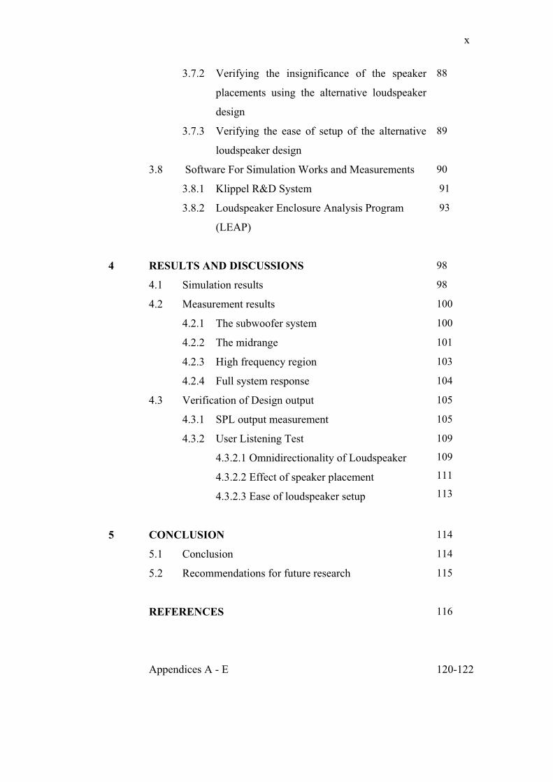
3.7.2 Verifying the insignificance of the speaker
placements using the alternative loudspeaker
design
88
3.7.3 Verifying the ease of setup of the alternative
loudspeaker design
89
3.8 Software For Simulation Works and Measurements 90
3.8.1 Klippel R&D System 91
3.8.2 Loudspeaker Enclosure Analysis Program
(LEAP)
93
4 RESULTS AND DISCUSSIONS 98
4.1 Simulation results 98
4.2 Measurement results 100
4.2.1 The subwoofer system 100
4.2.2 The midrange 101
4.2.3 High frequency region 103
4.2.4 Full system response 104
4.3 Verification of Design output 105
4.3.1 SPL output measurement 105
4.3.2 User Listening Test
4.3.2.1 Omnidirectionality of Loudspeaker
4.3.2.2 Effect of speaker placement
4.3.2.3 Ease of loudspeaker setup
109
109
111
113
5 CONCLUSION 114
5.1 Conclusion 114
5.2 Recommendations for future research 115
REFERENCES 116
Appendices A - E
120-122
xi
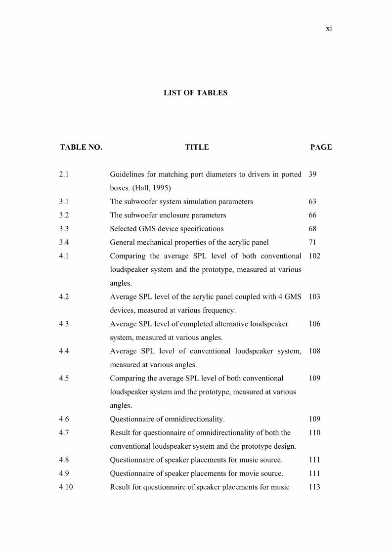
LIST OF TABLES
TABLE NO. TITLE PAGE
2.1 Guidelines for matching port diameters to drivers in ported
boxes. (Hall, 1995)
39
3.1 The subwoofer system simulation parameters 63
3.2 The subwoofer enclosure parameters 66
3.3 Selected GMS device specifications 68
3.4 General mechanical properties of the acrylic panel 71
4.1 Comparing the average SPL level of both conventional
loudspeaker system and the prototype, measured at various
angles.
102
4.2 Average SPL level of the acrylic panel coupled with 4 GMS
devices, measured at various frequency.
103
4.3 Average SPL level of completed alternative loudspeaker
system, measured at various angles.
106
4.4 Average SPL level of conventional loudspeaker system,
measured at various angles.
108
4.5
4.6
4.7
4.8
4.9
4.10
Comparing the average SPL level of both conventional
loudspeaker system and the prototype, measured at various
angles.
Questionnaire of omnidirectionality.
Result for questionnaire of omnidirectionality of both the
conventional loudspeaker system and the prototype design.
Questionnaire of speaker placements for music source.
Questionnaire of speaker placements for movie source.
Result for questionnaire of speaker placements for music
109
109
110
111
111
113

xii
4.11
and movie source of both the conventional loudspeaker
system and the prototype.
Questionnaire of the ease of setup.
113
xiii
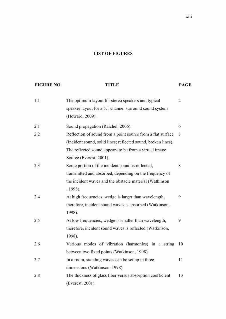
LIST OF FIGURES
FIGURE NO. TITLE PAGE
1.1 The optimum layout for stereo speakers and typical
speaker layout for a 5.1 channel surround sound system
(Howard, 2009).
2
2.1 Sound propagation (Raichel, 2006). 6
2.2 Reflection of sound from a point source from a flat surface
(Incident sound, solid lines; reflected sound, broken lines).
The reflected sound appears to be from a virtual image
Source (Everest, 2001).
8
2.3 Some portion of the incident sound is reflected,
transmitted and absorbed, depending on the frequency of
the incident waves and the obstacle material (Watkinson
, 1998).
8
2.4 At high frequencies, wedge is larger than wavelength,
therefore, incident sound waves is absorbed (Watkinson,
1998).
9
2.5 At low frequencies, wedge is smaller than wavelength,
therefore, incident sound waves is reflected (Watkinson,
1998).
9
2.6 Various modes of vibration (harmonics) in a string
between two fixed points (Watkinson, 1998).
10
2.7 In a room, standing waves can be set up in three
dimensions (Watkinson, 1998).
11
2.8 The thickness of glass fiber versus absorption coefficient
(Everest, 2001).
13
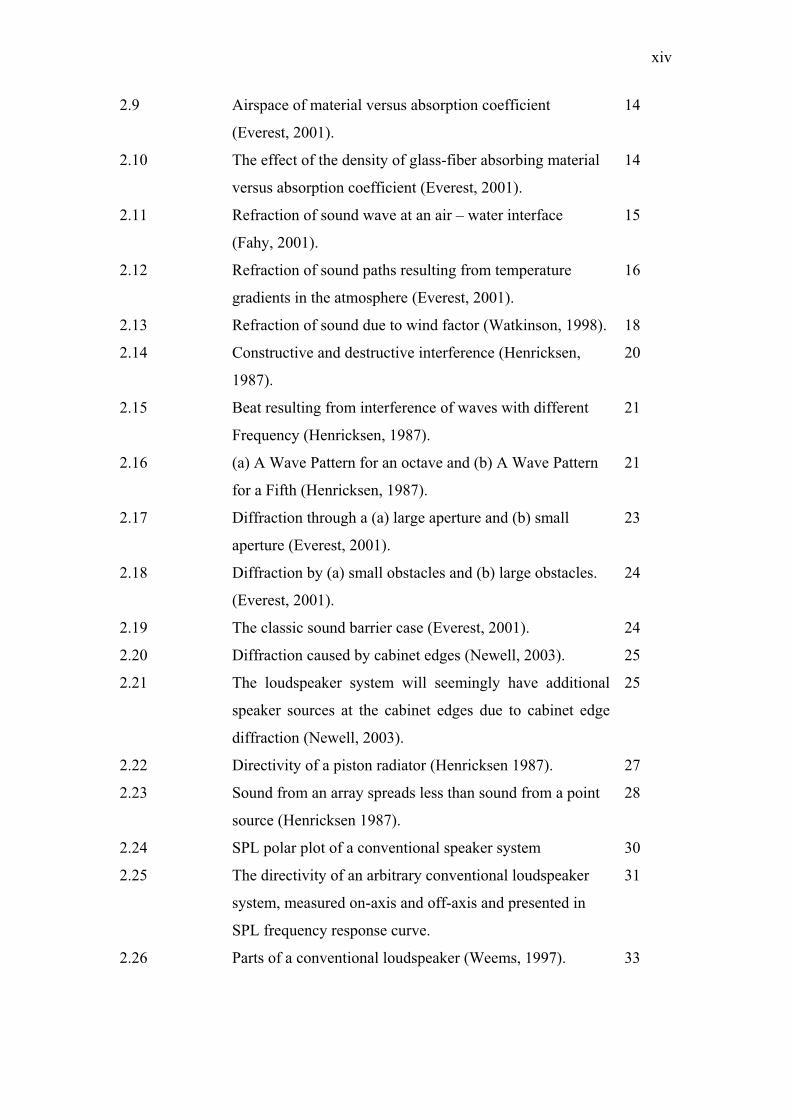
xiv
2.9 Airspace of material versus absorption coefficient
(Everest, 2001).
14
2.10 The effect of the density of glass-fiber absorbing material
versus absorption coefficient (Everest, 2001).
14
2.11 Refraction of sound wave at an air – water interface
(Fahy, 2001).
15
2.12 Refraction of sound paths resulting from temperature
gradients in the atmosphere (Everest, 2001).
16
2.13 Refraction of sound due to wind factor (Watkinson, 1998). 18
2.14 Constructive and destructive interference (Henricksen,
1987).
20
2.15 Beat resulting from interference of waves with different
Frequency (Henricksen, 1987).
21
2.16 (a) A Wave Pattern for an octave and (b) A Wave Pattern
for a Fifth (Henricksen, 1987).
21
2.17 Diffraction through a (a) large aperture and (b) small
aperture (Everest, 2001).
23
2.18 Diffraction by (a) small obstacles and (b) large obstacles.
(Everest, 2001).
24
2.19 The classic sound barrier case (Everest, 2001). 24
2.20 Diffraction caused by cabinet edges (Newell, 2003). 25
2.21 The loudspeaker system will seemingly have additional
speaker sources at the cabinet edges due to cabinet edge
diffraction (Newell, 2003).
25
2.22 Directivity of a piston radiator (Henricksen 1987). 27
2.23 Sound from an array spreads less than sound from a point
source (Henricksen 1987).
28
2.24 SPL polar plot of a conventional speaker system 30
2.25 The directivity of an arbitrary conventional loudspeaker
system, measured on-axis and off-axis and presented in
SPL frequency response curve.
31
2.26 Parts of a conventional loudspeaker (Weems, 1997). 33
xv
2.27 Impedance curve of an arbitrary driver (Hall, 1995). 34
2.28 Impedance response curve of a ported box enclosure
(Weems, 1997).
37
2.29 Deformation patterns of various types of wave in straight
bars and flat plates: (a) quasi-longitudinal wave; (b)
transverse (shear wave); (c) bending wave (Fahy, 2007).
44
2.30 Displacements and deformation of a beam element in
bending (Fahy, 2007).
45
2.31 Power response of a typical DML loudspeaker, showing f0
and 2.5f0 (Borwick, 2001).
46
2.32 Calculated modes for the DML panel above (Borwick,
2001).
46
2.33 (a)Propagation of pressure wave in air from conventional
speaker and (b)Propagation of pressure wave in air from
DML panel (Borwick, 2001).
48
2.34 Cross section of a typical moving coil NXT exciter 50
2.35 Deformation of a magnetostrictive material 52
2.36 Operation of a magnetostrictive material (Engdahl, 2000). 53
2.37 A generic GMS inner construction (Engdahl, 2000). 53
2.38 Terfenol-D response around room temperature, from Clark
(1980).
54
2.39 The forces on the faces of a unit cube in a stressed body
(Engdahl, 2000).
55
2.40 Undeformed (dashed) and deformed (solid) body The
general deformation shown in (a) can be represented by a
strain (b) plus a rotation (c) (Engdahl, 2000).
56
3.1 Implementation and research methodology of the design 62
3.2 TS parameters of the selected 25cm driver. (Measured by
Klippel system)
65
3.3 Selected 25 cm subwoofer speaker unit 65
3.4 The selected midrange driver 67
3.5 Parameters of the selected midrange driver. (Measured by
Klippel system)
67
xvi
3.6 The GMS device 69
3.7 Selected GMS frequency response 69
3.8 Selected GMS impedance curve 70
3.9 Selected GMS outer construction 70
3.10 3D model the DML panel. (Drawn by Pro E software) 71
3.11 A 29 cm 35 cm board with 24 cm diameter opening. 73
3.12 A 29 cm 35 cm board with 1 port opening, and 3 input
jack openings.
73
3.13 The 6 pieces of wood is being nailed together 73
3.14 Glue is applied around the three speaker input jacks at the
rear board.
74
3.15 The completed subwoofer system. 74
3.16 A 9 cm 9.4 cm opening for a 6 cm midrange driver unit. 75
3.17 Mounting the 6 cm midrange driver into the top opening. 75
3.18 Attaching the support poles for the actuators. 76
3.19 Fixing the 4 metal hooks into the top of the enclosure. 76
3.20 Balancing and mounting the acrylic board onto the
subwoofer enclosure using the suspension bridge design
concept.
77
3.21 The completed alternative loudspeaker system design. 77
3.22 Klippel Analyzer and signal amplifier 78
3.23 Inputs and outputs connection of the equipment 78
3.24 Mounting a loudspeaker unit on the Klippel apparatus 79
3.25 Adjusting microphone and laser sensors and connecting
the loudspeaker terminals to Klippel Analyzer.
79
3.26 Setting up to measure the entire alternative loudspeaker
system in an anechoic room.
80
3.27 Connecting the loudspeaker system to Klippel Analyzer. 81
3.28 The software environment of dB-Lab 82
3.29 Driver properties 82
3.30 Stimulus properties 82
3.31 Input connection and sensors 83
3.32 Measurement method 83
xvii
3.33 Stimulus properties for SPL measurement. 83
3.34 Input connections 84
3.35 Processing options 84
3.36 Display options 84
3.37 Input properties for measuring impedance 85
3.38 Processing properties for measuring impedance 85
3.39 Measuring the directivity of a conventional speaker (0°
and 360°)
86
3.40 Measuring the directivity of a conventional speaker (90°) 86
3.41 The alternative and conventional loudspeaker system
setup for verifying omnidirectionality
87
3.42
The prototype setup for verifying the insignificance of the
speaker placements
88
3.43 Simplified illustration of how the alternative loudspeaker
design can be connected to an amplifier
89
3.44 The Klippel Distortion Analyzer 91
3.45 The dB-Lab software environment. 92
3.46 Block diagram for LPM software module 92
3.47 Enclosure modeling in Enclosure Shop 93
3.48 The various graphs generated by EnclosureShop 94
3.49 The EnclosureShop software environment 94
3.50 The transducer parameters window 95
3.51 Volume parameters and other parameters 95
3.52 Port and port area parameters 96
3.53 Layout parameters window 97
3.54 Analysis parameters properties 97
4.1 The simulated SPL response of the selected 25 cm
subwoofer driver unit in the selected cabinet enclosure
(Simulated via EnclosureShop by LEAP).
99
4.2 The simulated impedance curve of the selected 25 cm
subwoofer driver unit in the selected cabinet enclosure
(Simulated via EnclosureShop by LEAP).
99
4.3 SPL curve of the completed 25 cm subwoofer system 100
xviii
(Measured by Klippel system).
4.4 Impedance curve of the completed 25 cm subwoofer
system (Measured by Klippel system).
101
4.5 SPL response curve comparing the subwoofer system and
the combined subwoofer-midrange system (Measured by
Klippel system).
102
4.6 SPL response curve of the acrylic panel coupled with 4
GMS devices (Measured by Klippel system).
103
4.7 Completed alternative loudspeaker system SPL response
curve (Measured by Klippel system).
104
4.8 Completed alternative loudspeaker system SPL response
curve at angles 0°/360°, 90°, 180°, and 270°(Measured by
Klippel system).
105
4.9 Completed alternative loudspeaker system SPL response
curve at angles 45°, 135°, 225°, and 315° (Measured by
Klippel system).
106
4.10 Conventional floorstand loudspeaker system SPL response
curve at angles 0°/360°, 90°, 180°, and 270°.
107
4.11 Conventional floorstand loudspeaker system SPL response
curve at angles 0°/360°, 45°, 135°, 225° and 315°
108
xix
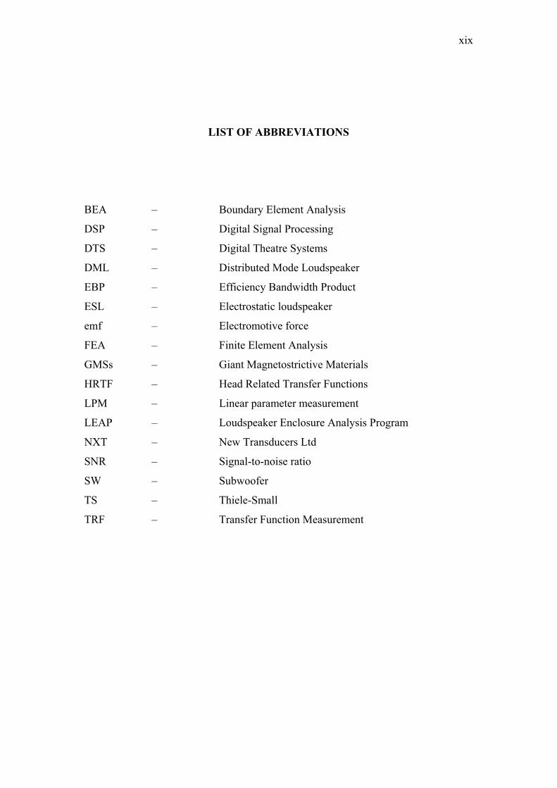
LIST OF ABBREVIATIONS
BEA – Boundary Element Analysis
DSP – Digital Signal Processing
DTS – Digital Theatre Systems
DML – Distributed Mode Loudspeaker
EBP – Efficiency Bandwidth Product
ESL – Electrostatic loudspeaker
emf – Electromotive force
FEA – Finite Element Analysis
GMSs – Giant Magnetostrictive Materials
HRTF – Head Related Transfer Functions
LPM – Linear parameter measurement
LEAP – Loudspeaker Enclosure Analysis Program
NXT – New Transducers Ltd
SNR – Signal-to-noise ratio
SW – Subwoofer
TS – Thiele-Small
TRF – Transfer Function Measurement
xx
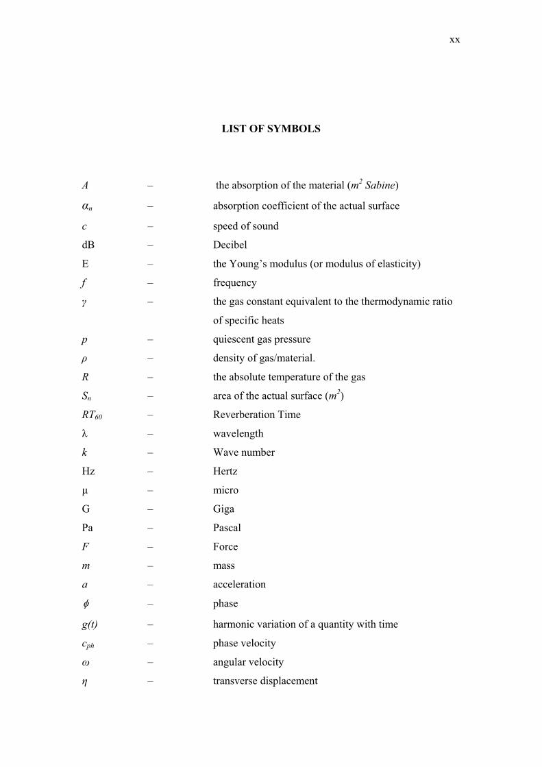
LIST OF SYMBOLS
A – the absorption of the material (m2 Sabine)
αn – absorption coefficient of the actual surface
c – speed of sound
dB – Decibel
E – the Young’s modulus (or modulus of elasticity)
f – frequency
γ – the gas constant equivalent to the thermodynamic ratio
of specific heats
p – quiescent gas pressure
ρ – density of gas/material.
R – the absolute temperature of the gas
Sn – area of the actual surface (m2)
RT60 – Reverberation Time
λ – wavelength
k – Wave number
Hz – Hertz
μ – micro
G – Giga
Pa – Pascal
F – Force
m – mass
a – acceleration
– phase
g(t) – harmonic variation of a quantity with time
cph – phase velocity
ω – angular velocity
η – transverse displacement
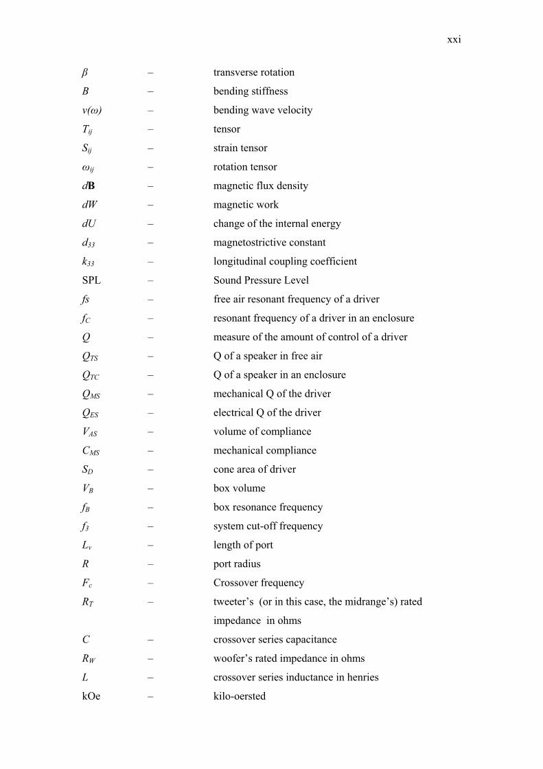
xxi
β – transverse rotation
B – bending stiffness
v(ω) – bending wave velocity
Tij – tensor
Sij – strain tensor
ωij – rotation tensor
dB – magnetic flux density
dW – magnetic work
dU – change of the internal energy
d33 – magnetostrictive constant
k33 – longitudinal coupling coefficient
SPL – Sound Pressure Level
fs – free air resonant frequency of a driver
fC – resonant frequency of a driver in an enclosure
Q – measure of the amount of control of a driver
QTS – Q of a speaker in free air
QTC – Q of a speaker in an enclosure
QMS – mechanical Q of the driver
QES – electrical Q of the driver
VAS – volume of compliance
CMS – mechanical compliance
SD – cone area of driver
VB – box volume
fB – box resonance frequency
f3 – system cut-off frequency
Lv – length of port
R – port radius
Fc – Crossover frequency
RT – tweeter’s (or in this case, the midrange’s) rated
impedance in ohms
C – crossover series capacitance
RW – woofer’s rated impedance in ohms
L – crossover series inductance in henries
kOe – kilo-oersted
xxii
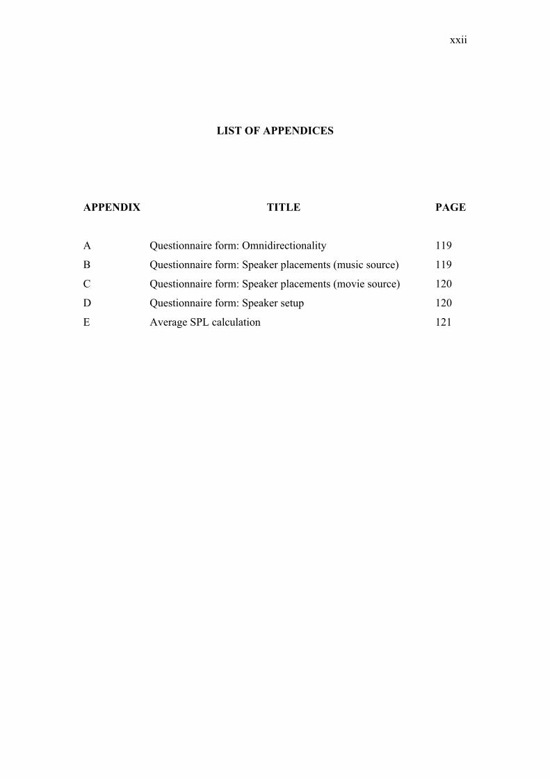
LIST OF APPENDICES
APPENDIX TITLE PAGE
A Questionnaire form: Omnidirectionality 119
B Questionnaire form: Speaker placements (music source) 119
C Questionnaire form: Speaker placements (movie source) 120
D Questionnaire form: Speaker setup 120
E Average SPL calculation 121
CHAPTER 1
INTRODUCTION
1.1 Introduction
Proper loudspeaker placement is the most important part for the setting up of
an audio system. This is to ensure that the system performs at its most optimum
condition. Proper placement of loudspeaker is crucial to the quality of the sound, as
improper loudspeaker placement can make a good audio system sound bad or
distracting, and degrades the quality of the loudspeakers itself.
1.2 Background
Improper speaker placement, perhaps due to the listener’s lack of experience
or knowledge in speaker placement can significantly affect the sound quality as
perceived by the listener. Howard (2009) states that it is pointless to have a wonderful
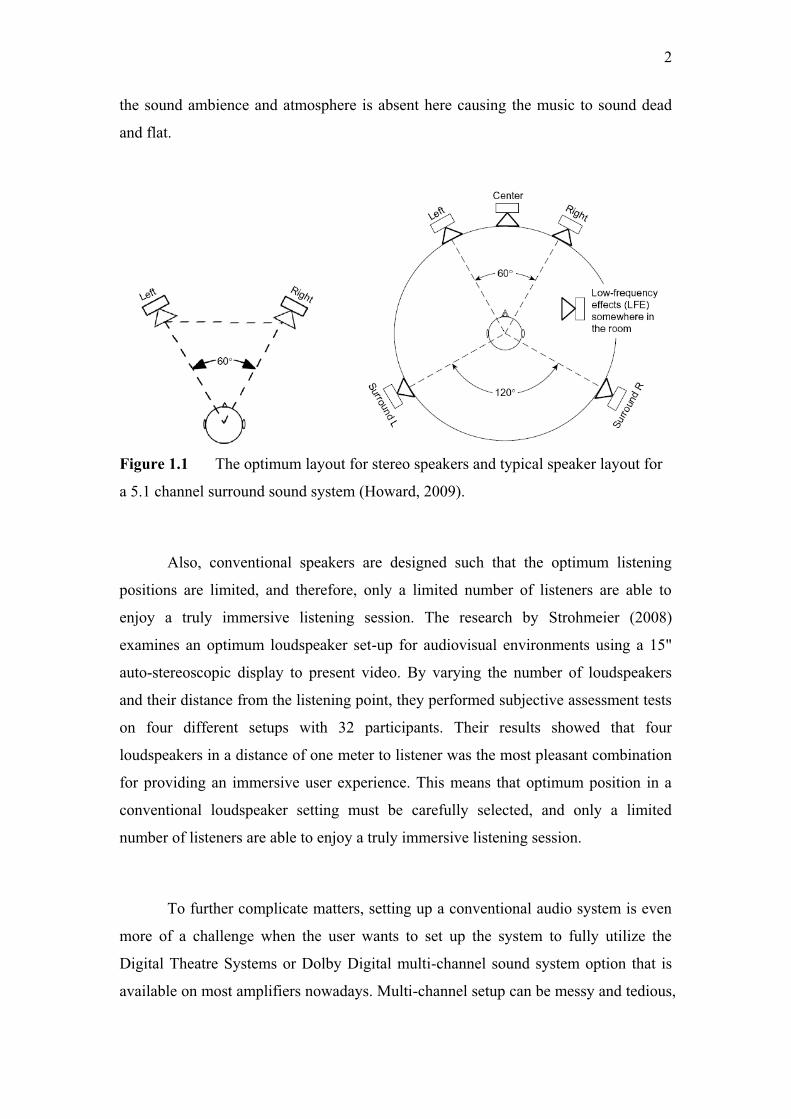
listening room if the speakers are not in an optimum position. Figure 1.1 shows the
optimum layout for stereo speakers and typical speaker layout for a 5.1 channel
surround sound system. According to Howard (2009), they should form an equilateral
triangle with the center of the listening position. If one has a greater angle than this,
the center phantom image becomes unstable, creating the so-called “hole-in-the-
middle” effect. However, having an angle of less than 60° results in a narrower stereo
image. Narrow stereo image is where all the sound seems focused in the middle and
2
the sound ambience and atmosphere is absent here causing the music to sound dead
and flat.
Figure 1.1 The optimum layout for stereo speakers and typical speaker layout for
a 5.1 channel surround sound system (Howard, 2009).
Also, conventional speakers are designed such that the optimum listening
positions are limited, and therefore, only a limited number of listeners are able to
enjoy a truly immersive listening session. The research by Strohmeier (2008)
examines an optimum loudspeaker set-up for audiovisual environments using a 15"
auto-stereoscopic display to present video. By varying the number of loudspeakers
and their distance from the listening point, they performed subjective assessment tests
on four different setups with 32 participants. Their results showed that four
loudspeakers in a distance of one meter to listener was the most pleasant combination
for providing an immersive user experience. This means that optimum position in a
conventional loudspeaker setting must be carefully selected, and only a limited
number of listeners are able to enjoy a truly immersive listening session.
To further complicate matters, setting up a conventional audio system is even
more of a challenge when the user wants to set up the system to fully utilize the
Digital Theatre Systems or Dolby Digital multi-channel sound system option that is
available on most amplifiers nowadays. Multi-channel setup can be messy and tedious,
3
and if set up wrongly, it may result in a bad sound image which the user may
unfortunately blame the poor sound quality on the performance of the audio
equipment, when what happened actually was just the wrong positioning of the
speakers.
1.3 Problem Statement
This research will attempt to design a single loudspeaker system that is
capable of reproducing 360° wide-angle soundstage with excellent sound quality,
where the users’ listening experience will be independent of the distance and position
from the loudspeaker. Based on the distributed mode loudspeaker (DML) concept, an
acoustically conductive surface is coupled with giant magnetostriction devices (GMS)
to produce an omnidirectional sound from the single speaker system. This alternative
loudspeaker system will also be a user-friendly system that is versatile and easy to
setup since it involves only a single loudspeaker, and it can be placed in any position
in a room.
1.4 Objective of the Study
The objectives of the study are as follows:
a. To design a versatile and high-quality loudspeaker system that can be
placed in any position, in a particular room.
b. To fabricate a quality single speaker system that is capable of reproducing
360° wide-angle soundstage (in the horizontal plane) that is independent of
distance and speaker position.
c. To design a user-friendly loudspeaker system that is easy to setup.
4
1.5 Scopes of the Study
The scopes of the study are as follows:
a. Adopt conventional loudspeaker design for construction of the subwoofer
system
b. Design suitable crossover network to cut-off at the high frequency and
midrange frequency band
c. Research suitable material to use for the DML panel and the GMS actuator
for the high frequency area.
d. Verify the completed system performance by measuring the directionality
of the loudspeaker system.
e. Use standard listening room with the dimensions of 7.3 meter long by 3.5
meter high and 5.9 meter wide for evaluation.
1.6 Contribution of the Study
The significance of this study are as follows:
a. An alternative loudspeaker device using GMS material as an actuator is
implemented to achieve a single-loudspeaker system. Users find it easier to
setup a single-loudspeaker system, rather than the complicated setup of a
conventional speaker system, as verified in Section 4.3.
b. The alternative loudspeaker system is capable of delivering enough and
consistent sound pressure level with a sensitivity of 77 dB/1W at 1m, to all
the listeners, at all angles (0º – 360º) in the horizontal plane, as verified in
Section 4.2.4.
c. New loudspeaker sound waves reproduction concept, the DML concept, is
used to achieve an omni-directional sound field. The omni-directionality of
the alternative loudspeaker system is verified in Section 4.3.