Embed Size (px)
Citation preview

ii
PERFORMANCE PREDICTION FOR HIGH SPEED CRAFT
ANUAR BIN BERO
A dissertation submitted in partial fulfillment of the
requirements for the award of the degree of
Master of Engineering (Marine Technology)
Faculty of Mechanical Engineering
Universiti Teknologi Malaysia
MAY 2009

iv
Dedicated with love to my wife and children

v
ACKNOWLEDGEMENT
In the name of ALLAH the most Merciful and praise to Prophet Muhamad
S.A.W, i am able to complete my thesis. I wish to express my sincere appreciation to
my thesis supervisor Ir. Dr. Mohamad Pauzi bin Abd Ghani for encouragement,
guidance, critics and friendship. Without his continued support and concern, this
thesis would not have been completed.
I also would like to express my gratitude to Researcher Officer and all
technicians at Marine Technology Laboratory, UTM for assisting me in conducting
model testing. I am also thankful to Librarians of Universiti Teknologi Malaysia
(PSZ UTM Skudai) for their assistance in providing the relevant literatures.
Furthermore, i want to express my appreciation to my Head of Engineering Faculty,
Cdr Mazlan Bin Yassin RMN for his support and motivation while completing this
thesis.
Special gratitude to my beloved wife Habsah and children Iman and Hazim
for their support and inspiration during my research study. Also thank to my mother,
father and to my colleague, your support will be remembered.

vi
ABSTRACT
Generally the performance of the high speed craft can be divided into six
main components such as resistance and powering, propulsion, dynamic instability,
seakeeping and manoeuvring. Performance prediction on high speed craft especially
in planing hull is complicated due to complex combination of ship behaviour in
rough sea condition. The performance of high speed craft is becoming more
important due to their various functions and purposes to marine community which is
unable to be predicted using conventional methods. The fundamental of this research
is to study the two main components of the vessel i.e. resistance and seakeeping
quality by incorporating stern foil at aft portion planing craft (M Hull) that gives
significant effect to the performance of the vessel. Theoretically, stern foil has a
similar function with transom flap, trim wedges and trim tab which is to reduce the
resistance and also as a damping for motion reduction. In the scope of resistance
performance for this vessel with stern foil, the Savitsky and two dimensional
Methods are used for resistance prediction at different angle of attack. While
Computational Methods i.e. SEAKEEPER program was applied to seakeeping
prediction in regular wave (head sea). Both result of resistance and seakeeping
performance prediction was validated by conducting model test for the model with
and without stern foil. The performance of ship model with stern foil gives a positive
performance in term of seakeeping quality at constructive resistance. By adapting
with stern foil the heave and pitch Response Amplitude Operator (RAO) trim down
by 4.0% and 18.91% respectively. Furthermore, the reduction of forward and aft
acceleration RAO also occurs concurrently which the decreasing of both acceleration
are 21.10% and 6.14%.

vii
ABSTRAK
Secara amnya, prestasi kapal laju dibahagikan kepada enam komponen utama
iaitu rintangan dan daya tujahan, dorongan, ketidakstabilan dinamik, seakeeping dan
manoeuvring. Anggaran terhadap prestasi kapal laju terutamanya planing hull adalah
sangat sukar disebabkan gandingan sifat kapal yang komplek pada keadaan laut yang
bergelora. Kajian ini lebih menumpukan kepada dua perkara iaitu rintangan dan
kualiti seakeeping pada kapal laju berbentuk M Hull yang dipasang dengan foil
buritan. Secara teori, foil buritan mempunyai fungsi yang sama dengan kepak
buritan, baji buritan dan trim tab yang mana berpotensi bagi mengurangkan rintangan
dan juga sebagai peredam untuk meminimumkan pergerakan kapal. Kaedah
anggaran Savitsky dan dua dimensi telah diaplikasi bagi mengira prestasi rintangan
kapal yang mempunyai sudut pesongan yang berbeza. Sementara program simulasi
SEAKEEPER pula digunakan dalam anggaran sifat kapal seperti heave, pitch,
pecutan haluan dan buritan pada keadaan ombak yang seragam. Hasil keputusan
secara teori bagi pengiraan rintangan dan simulasi seakeeping dibandingkan dengan
keputusan data ujian rintangan dan ujian seakeeping untuk mengesahkan prestasi
kapal dengan foil buritan atau sebaliknya. Ini dibuktikan secara eksperimen, dengan
memasang foil buritan prestasi kapal laju dapat ditingkatkan yang mana pengurangan
heave RAO sebanyak 4% dan pitch RAO 18.91%. Malahan pecutan haluan dan
buritan juga berkurang, masing-masing menunjukkan prestasi dapat ditingkatkan
sehingga 21.10% dan 6.14%.

viii
TABLE OF CONTENTS
CHAPTER TITLE PAGE
DECLARATION i
DEDICATION iv
ACKNOWLEDGEMENTS v
ABSTRACT vi
ABSTRAK vii
TABLE OF CONTENTS viii
LIST OF TABLES xii
LIST OF FIGURES xiv
NOMENCLATURE xix
LIST OF APPENDICES xxiii
1 INTRODUCTION 1
1.1 Background of Study 1
1.2 Objective 2
1.3 Scope of Work 2
1.4 Schedule of the Project 2
1.4.1 Project I 2
1.4.2 Project II 3
2 LITERATURE REVIEW 5
2.1 Introduction 5
2.2 Planing Craft 7
2.2.1 Geometry of Planing Craft 8

ix
2.3 Behaviour of Planing Craft 10
2.3.1 Calm Water 10
2.3.2 Rough Water 12
2.4 Hydrodynamic forces on Planing Craft 16
2.5 Transom or Stern Flap Performance 21
2.6 Theory of Foil 23
2.6.1 Physical Features of a Foil 25
2.6.2 Selection of Foil and Strut 26
3 METHODOLOGY 29
3.1 Introduction 29
3.2 Resistance 29
3.3 Seakeeping 34
3.4 Concluding Remarks 39
4 RESISTANCE 40
4.1 Introduction 40
4.2 Resistance Components 41
4.3 Savitsky Method 44
4.4 Controllable Transom Flaps (Trim Tabs) 47
4.5 Stern Foil 49
4.6 Resistance Components on the Foil and Strut 51
4.6.1 Viscous Resistance 51
4.6.2 The Induced Resistance 53
4.6.3 Wave Resistance 54
4.6.4 Spray Resistance 57
4.7 The Combination Total Resistance 57
4.8 Sinkage and Trim 58
4.9 Program Development of Resistance Prediction 59
4.10 Concluding Remarks 59
5 SEAWORTHINESS 60

x
5.1 Introduction 60
5.2 Regular Waves 64
5.3 Motion in Regular Waves 65
5.3.1 Lateral Plane Motion in Regular Beam Seas 65
5.3.2 Vertical Plane Motion in Regular Head Waves
66
5.4 Couple Heave and Pitch Motion in Head Sea 66
5.4.1 Basic Concept of Couple Heave and Pitch Motion
68
5.5 Calculation Method for Vertical Motions by effect of Stern Foil
69
5.5.1 Exciting Forces and Moments due to Stern Foil for Planing Hull
70
5.5.2 Solution of the Motion Equation with Stern Foil
72
5.6 SEAKEEPER Program 73
5.6.1 Coordinate System 74
5.6.2 Wave Spectra 75
5.6.3 Idealised Spectra 76
5.6.4 Encounter Spectrum 77
5.6.5 Characterising Vessel Response 77
5.6.6 Response Amplitude Operator (RAO) 77
5.6.7 Calculating Vessel Motions 78
5.7 Concluding Remarks 78
6 RESEARCH OBJECT 80
6.1 Introduction 80
6.2 Concluding Remarks 84
7 ANALYSIS 85
7.1 Introduction 85
7.2 Resistance Analysis 86

xi
7.3 Seakeeping Analysis 93
7.4 Concluding Remarks 103
8 CONCLUSION 104
8.1 Conclusion 104
8.2 Future Work 105
REFERENCES 106
Appendices A-E 110-161
xii
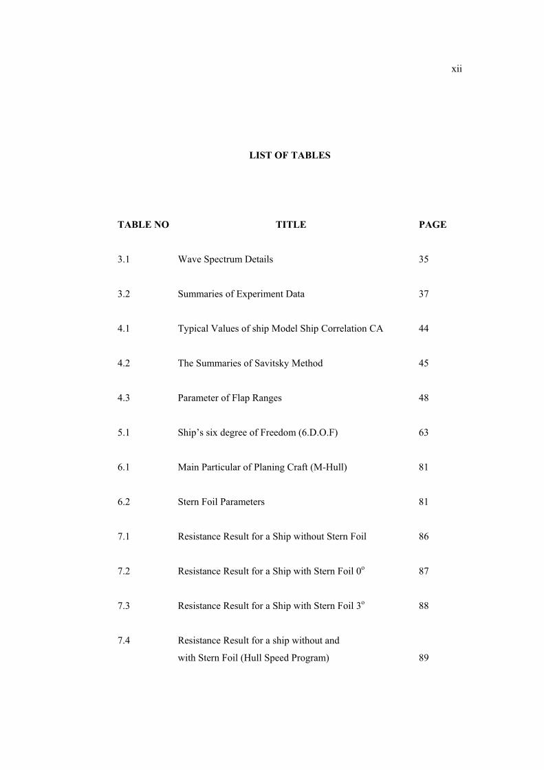
LIST OF TABLES
TABLE NO TITLE PAGE
3.1 Wave Spectrum Details 35
3.2 Summaries of Experiment Data 37
4.1 Typical Values of ship Model Ship Correlation CA 44
4.2 The Summaries of Savitsky Method 45
4.3 Parameter of Flap Ranges 48
5.1 Ship’s six degree of Freedom (6.D.O.F) 63
6.1 Main Particular of Planing Craft (M-Hull) 81
6.2 Stern Foil Parameters 81
7.1 Resistance Result for a Ship without Stern Foil 86
7.2 Resistance Result for a Ship with Stern Foil 0o 87
7.3 Resistance Result for a Ship with Stern Foil 3o 88
7.4 Resistance Result for a ship without and
with Stern Foil (Hull Speed Program) 89

xiii
7.5 Sinkage and Trim Result for a Ship without and
with Stern Foil 92
7.6 Experiment Result Heave and Pitch RAO 93
7.7 Calculation Result Heave and Pitch RAO
using Strip Theory 95
7.8 Forward and Aft Acceleration RAO without and
with Stern Foil 99

xiv
LIST OF FIGURES
FIGURE NO TITLE PAGE
1.1 Project Flowchart 4
2.1 Forces Acting on a Planing Hull 6
2.2 The Simplest Geometry of Planing Surface 9
2.3 The Main Features of a Prismatic Planing Surface 10
2.4 Spring Mass System 13
2.5 Response of a Linear Spring Mass System 15
2.6 Resistance Curves of Planing Hull L/B=3.1 16
2.7 Resistance Curves of Planing Hull L/B=7.0 17
2.8 The Location of Stern Flap 22
2.9 The Flap is mounted to the Transom at an Angle Relative
to the Ship Centerline Buttock 22
2.10 Typical Foil Lift Curves 25
2.11a Foil Parameters Plan View 26

xv
2.11b Foil Parameters Sectional View 26
2.12 Foil Configuration 27
2.13 Dimension of the Research Foil and Strut 27
2.14 Resistance and Motion Optimisation at 0o Angle of Attack 28
2.15 The Drag Coefficient as a Function of Angle of Attack 28
3.1 The Flowchart of FORTRAN Programming for Resistance 31
3.2 The Flowchart of Subroutine FORTRAN Programming
for Resistance Prediction 32
3.3 The Flowchart of Resistance Test Procedure 33
3.4 The Flowchart of Motion Prediction using SEAKEEPER 36
3.5 The Flowchart of Seakeeping Test Procedure 38
4.1 Breakdown of Resistance in Components 41
4.2 Force Act on Planing Hull 45
4.3 Planing Hull with Transom Flap 48
4.4 Lifting Effect on Planing Vessel 50
4.5 The Drag Force on Foil by using Conservation
of Fluid Momentum 51
4.6 Steady Potential Flow Past a Two Dim. Infinite Fluid 53

xvi
4.7 The Flow due to the Foil by Two Vertices
with Opposite Circulation 56
5.1 Long Wen’s Experiment Model 62
5.2 Prismatic Hull Model 62
5.3 Types of Ship Motions 63
5.4 Regular Waves Generated in Towing Tank 65
5.5 The High Speed Craft (M-Hull) Incorporated Stern Foil 69
5.6 Theory of Wing 71
5.7 Effective Length of Stern Foil 72
5.8 Coordinate System in SEAKEEPER Program 74
5.9 Wave Direction in SEAKEEPER Program 75
5.10 Typical Wave Spectrums 76
5.11 Typical Heave and Pitch RAO’s 78
6.1 Body Plan of Planing Craft (M-Hull) without Stern Foil 82
6.2 Body Plan of Planing Craft (M-Hull) with Stern Foil 82
6.3 Resistance Test without Stern Foil 83
6.4 Resistance Test with Stern Foil 83
6.5 Wave Contour in Seakeeping Test 83

xvii
6.6 Seakeeping Test in Progress 84
7.1 The Vessel Installed with Stern Foil 85
7.2 Graphs on Comparison between Theory and Experiment
for Resistance without Stern Foil 87
7.3 Graphs on Comparison between Theory and Experiment
for Resistance with Stern Foil at 0o Angle of Attack 88
7.4 Graphs on Comparison between Theory and Experiment
for Resistance with Stern Foil at 3o Angle Of Attack 89
7.5 Graphs on Comparison Ship Resistance for without and with
Stern Foil (Savitsky Method and Hull Speed Program) 90
7.6 Graphs on Comparison between a Ship without and
with Stern Foil (EXP) 90
7.7 Graphs on Comparison between a Ship with and
without Stern Foil (Theory) 91
7.8 Graphs on Comparison of Sinkage between a Ship
with and without Stern Foil 92
7.9 Graphs on Comparison of Trim between a Ship
with and without Stern Foil 92
7.10 Graphs on Comparison of Heave And Pitch RAO
in Different Method for a Ship with Stern Foil 94
7.11 Graphs on Comparison Heave RAO (SEAKEEPER) 96
7.12 Graphs on Comparison Heave RAO (Experiment) 96
xviii
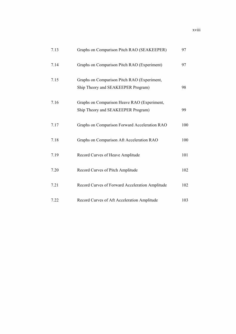
7.13 Graphs on Comparison Pitch RAO (SEAKEEPER) 97
7.14 Graphs on Comparison Pitch RAO (Experiment) 97
7.15 Graphs on Comparison Pitch RAO (Experiment,
Ship Theory and SEAKEEPER Program) 98
7.16 Graphs on Comparison Heave RAO (Experiment,
Ship Theory and SEAKEEPER Program) 99
7.17 Graphs on Comparison Forward Acceleration RAO 100
7.18 Graphs on Comparison Aft Acceleration RAO 100
7.19 Record Curves of Heave Amplitude 101
7.20 Record Curves of Pitch Amplitude 102
7.21 Record Curves of Forward Acceleration Amplitude 102
7.22 Record Curves of Aft Acceleration Amplitude 103

xix
NOMENCLATURE
LOA - Length Overall (m)
LWL - Length waterline (m)
Boa - Breadth overall (m)
BWL - Breadth at waterline (m)
T - Moulded draft (m)
� - Displacement (tone)
� - Volume (m3)
V - Ship speed (m/s)
LCB - Longitudinal Centre of Buoyancy (m)
LCG - Longitudinal Centre of Gravity, from transom (m)
B/T - Breadth draught ratio
L/B - Length breadth ratio
L/�1/3 - Length-displacement ratio
g - Specific gravity (9.81m/s2)
� - Mass density, (1025 kg/m3)
� - Kinematic velocity, m2/s
Rn - Renault number ���
Fn - Froude number V/�gL
S - Wetted surface area
RT - Total resistance (N)
RF - Friction resistance according to the ITTC-1957 friction formula (N)
RR - Residual resistance (N)
PE - Effective power (kW)
1 + k1 - Form factor the viscous resistance of the hull form in relation to RF
CF - Coefficient of friction CR - Residuary resistance coefficient

xx
CA - Ship model-ship correlation
CT - Total resistance coefficient
iE - The angle measured in the plane of the water plane, between the hull
and the centerline (deg)
� - Deadrise angle (deg)
CB - Block coefficient
CWP - Waterplane area coefficient
RW - wave resistance CM - Midships coefficient
CP - Prismatic coefficient ��� - Speed Coefficient ���� - Trim angle (deg) ���� - Flat plate lift coefficient �� � - The lift coefficient for finite deadrise
- Wetted length beam ratio
k - Wetted length of the keel (m) � - Vessel Displacement (N) ���� - Renault Number based on BWL ���� - Correction factor which obtained from ATTC Standard Roughness �� - Linearized Integral �� - Vertical Inflow Velocity � - Velocity Potential
- Circulation � - Foil Drag �� - Viscous resistance Foil or Strut (N) ��� - Viscous resistance coefficient Foil or Strut �� - Lift Force due to Viscous ��� - Lift coefficient due to Viscous �� - Friction coefficient ��� - Reynolds number Chord Based
t/c - Foil thickness to chord ratio
V - Ship speed (m/s)
C - Chord length (m)

xxi
� - Kinematic viscosity (m2/s)
A - Planform area Foil or Strut (m) �� - Induced resistance Foil or Strut (N) �� - Lifting Force (induced) Foil or Strut ��� - Induced resistance coefficient ��� - Lift coefficient
- Aspect ratio, � !"�#$ % - Angle of attack (radian)
c0 - Chord length at midspan (m)
A - Planform area (projected area of the elliptical foil ,�&'�$ (m2)
s- - Span length (m) ()*+ - Complex wave amplitude function
B - Parabolic strut ��� - Lift coefficient (wave) �� - Wave resistance Foil (N) ��� - Wave resistance coefficient ��� - Lift coefficient , - Maximum camber (m) �! - Spray Resistance -. - The sum of various fluid forces (vertical hydrodynamic forces as well
as the wave excitation force) -/ - The sum of corresponding moments acting on the vessel because of
relative motion of vessel and wave. 012 032 0 - Heave acceleration, velocity and displacement, respectively. *1 2 *3 2 * - Pitch angular acceleration, velocity and displacement respectively.
�/g - Mass of vessel. �44 - Pitch inertia moment of vessel. 5662 7662 8662 5692 7692 8692 5992 7992 8992 5962 7962 896- Stability derivatives �. - Foil excited force �/ - Foil excited moment
� - Amplitude of heaving (m)
� - Maximum slope of the surface wave
� - Frequency of the surface

xxii
� - Phase angle between exciting moment and wave elevation
�0 - Wave frequency
� - Tuning factor = � / �0
� - Magnification factor = 1 / { ( 1- �2 )2 + 4k2 �2 } ½
�� - Added mass moment of Inertia 2k xx - Radius of gyration
1 - phase angle between exciting moment and wave elevation

xxiii
LIST OF APPENDICES
APPENDIX TITLE PAGE
A Details Planning for Project I and II 110 B Resistance and Seakeeping Test 112 C Sample of Resistance Prediction 130 D FORTRAN Programming on Resistance Prediction 141 E Offset Table 130.275 Tonnes High Speed Craft 160

CHAPTER 1
INTRODUCTION
1.1 Background of Study
Generally, the performance of high speed craft is difficult to obtain due to
several factors that shall be considered by designer such as resistance and powering,
propulsion, dynamic instability, seakeeping and manoeuvring criteria. Normally, all
these considerations are not fully achieved due to low budget and the owner has to
cut cost. Another factor that contributes to the failure of performance of high speed
craft is many of the assumptions used either with numerical or experimental
techniques. The formulation of conventional vessel is not suitable for predicting the
performance of high speed craft especially after several modifications has been
conducted on their hullform.
High speed crafts are known to have rough water problem is essentially one
of compromise between speed and seakeeping performance. As the speed of vessels
increases, the resistance also increase and required more power to move. At high
speed regime, the seakeeping becomes more important especially for passengers
vessel and vessel fit in with high technology equipment. However, speed is the main
factor and followed by comfort condition (seakeeping quality) to be considered
during preliminary design of this vessel and that factor must go well with rough sea
condition in order to achieve the mission or task within time frame.
In this study will discuss in detail the performance prediction of high speed
craft in term of resistance and seakeeping quality for the high speed craft (planing
2
craft M-hull) before and after incorporating with stern foil. The reason of this
adapting of a stern flap foil is to combine the seakeeping qualities of the vessel with
the dynamic effect and higher speed attainable at favourable ship resistance.
1.2 Objective
1. To investigate the effect of stern foil on resistance and seakeeping of M-Hull
Planing Craft.
1.3 Scope of Work
1. Literature review on stern foil analysis of M-Hull Planing Craft.
2. To develop a computer program for resistance prediction of M-Hull Planing
Craft by using Savitsky and two dimensional methods with effect of stern foil.
3. To perform seakeeping analysis by using an existing computational software
Maxsurf SEAKEEPER.
4. To conduct resistance and seakeeping tests with and without stern foil.
1.4 Schedule of the Project
1.4.1 Project I
1. Literature review on resistance and seakeeping behaviour of high speed craft.
The study shall begin by determining the characteristic of the parameters of high
speed craft in high speed region. The study also expands on the effect of tool for

3
controlling motion in waves which gives a significant effect to the speed of the
vessel.
2. The work will be continued with collecting all data and ships particulars
including hydrostatic data, drawing and materials for appropriate vessel which is
related to research objectives.
3. Perform the theoretical calculation and introduce the Savitsky equation and
develop the foil and strut formulation in FORTRAN programming to predict the
resistance of effect of stern flap foil on research vessel.
4. Conduct seakeeping simulation by using SEAKEEPER programming in order
to predict the motions by effect of stern flap foil.
1.4.2 Project II
1. A model will be constructed at Marine Technology Laboratory, Universiti
Teknologi Malaysia UTM.
2. Model test shall be conducted in order to assess the theory of performance of
high speed craft against the results from model test. Basically the purposes of this
experiment are:
a. To determine the resistance of the vessel with and without stern foil at speed
of 25 knots (12.86m/s).
b. To determine the significant effect of motions (heave and pitch) in head sea at
design speed with and without stern foil.
c. To confirm that by adapting stern flap foil at transom stern to the motion of
the vessel will decrease at vertical acceleration.
4
3. To perform the performance comparison for research ship between the results
of model test and theoretical estimates.
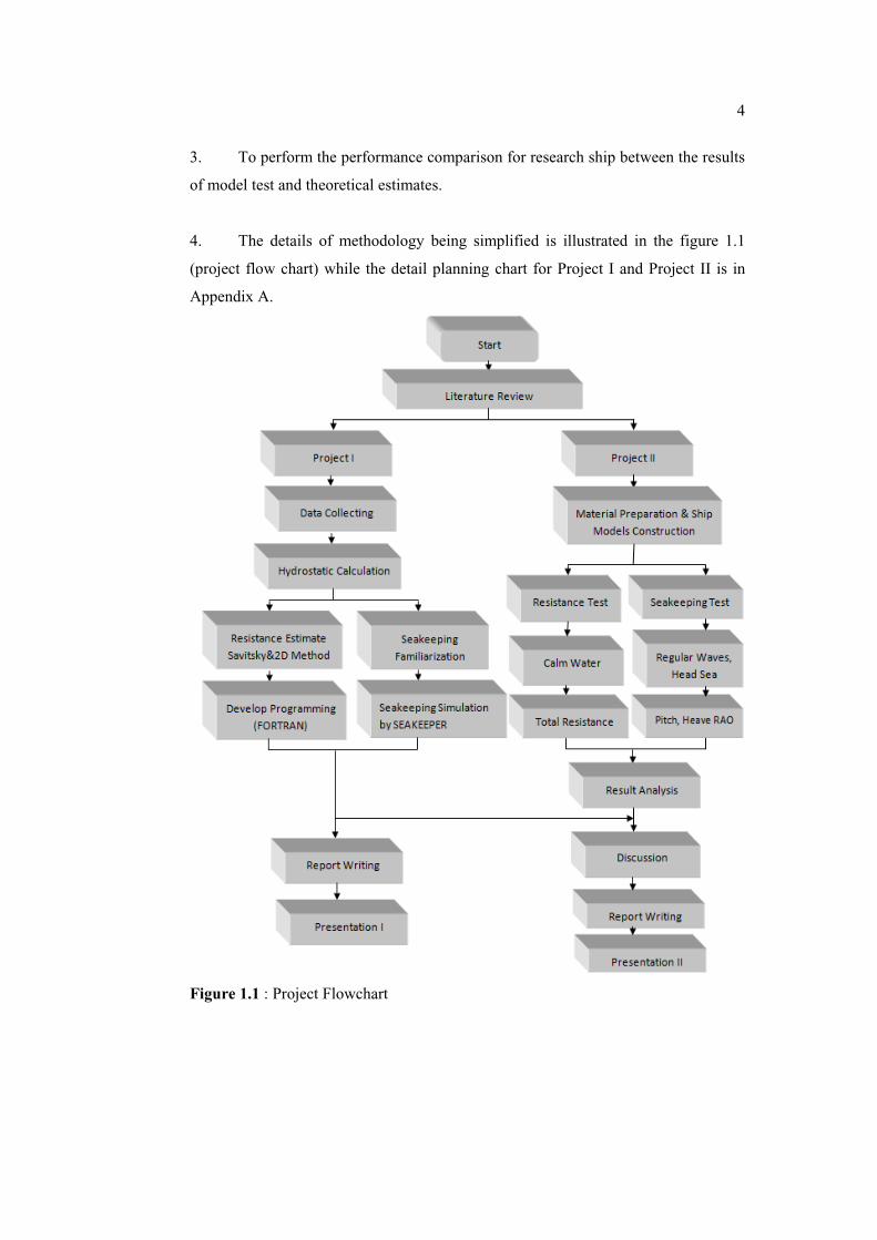
4. The details of methodology being simplified is illustrated in the figure 1.1
(project flow chart) while the detail planning chart for Project I and Project II is in
Appendix A.
Figure 1.1 : Project Flowchart