Embed Size (px)
Citation preview

A DIVISION OR SUBSIDIARY OF DOUGLAS DYNAMICS, L.L.C.
August 1, 2006Lit. No. 27554, Rev. 08
CAUTIONRead this document before installing thesnowplow.
CAUTIONSee your sales outlet for specific vehicleapplication recommendations beforeinstallation. The Kit Selection Guide/SelectionList has specific vehicle and snowplowrequirements.
27550OFF TRUCK COMPONENTS
PERSONAL PLOW
Installation Instructions

August 1, 2006 2 Lit. No. 27554, Rev. 08
27550
NOTE: Indicates a situation or action that can leadto damage to your snowplow and vehicle or otherproperty. Other useful information can also bedescribed.
SAFETY DEFINITIONS WARNING/CAUTION AND INSTRUCTIONLABELS
Become familiar with and inform users about the warninglabel and instruction label on the back of the blade.
NOTE: If labels are missing or cannot be read, seeyour sales outlet.
Warning/Caution Label
CAUTIONIndicates a potentially hazardous situation that,if not avoided, may result in minor or moderateinjury. It may also be used to alert againstunsafe practices.
Instruction Label
27155
ON
OFF
ConnectingPin
JackRetainer
Jack Sleeve
Jack
Jack HandlePlow Gear
Receiver Assembly
AttachmentArm
U.S. Patents 4,999,935; 5,420,480; 6,253,470; RE35,700; CAN Patent 2,060,425; and other patents pending.
Read Owner's Manual for Complete Instructions
4. Loosen one jack handle and slide jack sleeve down below jack retainer. Remove jack and retighten jack handle. Repeat for other jack and store them.
5. Connect all electrical cables from vehicle to snowplow.
1. Make certain both connecting pins are fully retracted.
2. Drive vehicle slowly to completely insert attachment arms into receiver assembly slots.
3. Twist both connecting pins to release spring tension, then push plow gear toward vehicle so connecting pins fully engage holes in attachment arms.
AT
TA
CH
INS
TR
UC
TIO
NS
3. While pushing plow gear toward vehicle to release connecting pin tension, pull connecting pin out on one side and twist pin handle to keep pin retracted. Repeat procedure for other connecting pin.
4. Disconnect all electrical cables.
DE
TA
CH
INS
TR
UC
TIO
NS
1. Put blade on ground using LOWER/ FLOAT on snowplow control. Leave control ON and in FLOAT.
2. Attach jacks. Loosen jack handle, put jack on ground, and raise jack sleeve until fully engaging jack retainer. Tighten jack handle. Repeat for other jack.
5. Back vehicle away from snowplow.
6. See Owner's Manual for proper snowplow storage.
This snowplow is for personal/homeowner use only.This snowplow is for personal/homeowner use only.This snowplow is for personal/homeowner use only.
WARNINGIndicates a potentially hazardous situation that,if not avoided, could result in death or seriouspersonal injury.
Lit. No. 27554, Rev. 08 3 August 1 , 2006
27550
PERSONAL SAFETY
• Remove ignition key and put the vehicle in park or ingear to prevent others from starting the vehicleduring installation or service.
• Wear only snug-fitting clothing while working onyour vehicle or snowplow.
• Do not wear jewelry or a necktie, and secure longhair.
• Wear safety goggles to protect your eyes frombattery acid, gasoline, dirt, and dust.
• Avoid touching hot surfaces such as the engine,radiator, hoses, and exhaust pipes.
• Always have a fire extinguisher rated BC handy, forflammable liquids and electrical fires.
HYDRAULIC SAFETY
• Always inspect hydraulic components and hosesbefore using. Replace any damaged or worn partsimmediately.
• If you suspect a hose leak, DO NOT use your handto locate it. Use a piece of cardboard or wood.
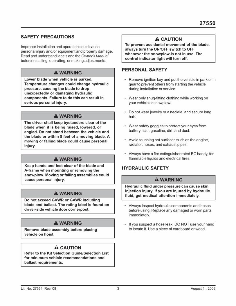
SAFETY PRECAUTIONS
Improper installation and operation could causepersonal injury and/or equipment and property damage.Read and understand labels and the Owner’s Manualbefore installing, operating, or making adjustments.
CAUTIONRefer to the Kit Selection Guide/Selection Listfor minimum vehicle recommendations andballast requirements.
WARNINGDo not exceed GVWR or GAWR includingblade and ballast. The rating label is found ondriver-side vehicle door cornerpost.
WARNINGKeep hands and feet clear of the blade andA-frame when mounting or removing thesnowplow. Moving or falling assemblies couldcause personal injury.
WARNINGRemove blade assembly before placingvehicle on hoist.
WARNINGLower blade when vehicle is parked.Temperature changes could change hydraulicpressure, causing the blade to dropunexpectedly or damaging hydrauliccomponents. Failure to do this can result inserious personal injury.
WARNINGThe driver shall keep bystanders clear of theblade when it is being raised, lowered, orangled. Do not stand between the vehicle andthe blade or within 8 feet of a moving blade. Amoving or falling blade could cause personalinjury.
CAUTIONTo prevent accidental movement of the blade,always turn the ON/OFF switch to OFFwhenever the snowplow is not in use. Thecontrol indicator light will turn off.
WARNINGHydraulic fluid under pressure can cause skininjection injury. If you are injured by hydraulicfluid, get medical attention immediately.

August 1, 2006 4 Lit. No. 27554, Rev. 08
27550
TORQUE CHART
Recommended Fastener Torque Chart (Ft.-Lb.)
SizeSAE
Grade 2SAE
Grade 5SAE
Grade 8
1/4-205/16-183/8-163/8-247/16-141/2-139/16-125/8-11 3/4-10 7/8-9 1-8
611192430456693150150220
91831465075110150250378583
1328 46 68 75 115 165 225 370 591 893
Metric Grade 8.8 (Ft.-Lb.)
Size TorqueSizeTorque
M 6M 8M 10
M 12M 14M 16
717 35
60 95 155
These torque values apply to fastenersexcept those noted in the instruction.
WARNINGVehicle exhaust contains lethal fumes.Breathing these fumes, even in lowconcentrations, can cause death. Neveroperate a vehicle in an enclosed area withoutventing exhaust to the outside.
CAUTIONRead instructions before assembling. Fastenersshould be finger tight until instructed to tightenaccording to the torque chart. Use standardmethods and practices when attachingsnowplow, including proper personalprotective safety equipment.
WARNINGGasoline is highly flammable, and gasolinevapor is explosive. Never smoke while workingon a vehicle. Keep all open flames away fromgasoline tanks and lines. Wipe up any spilledgasoline immediately.
FUSES
The electrical and hydraulic systems contain severalblade-style automotive fuses. If a problem should occurand fuse replacement is necessary, the replacementfuse must be of the same type and amperage rating asthe original. Installing a fuse with a higher rating candamage the system and could start a fire. FuseReplacement, including fuse ratings and locations, islocated in the Maintenance Section of the Owner’sManual.
FIRE AND EXPLOSION
Be careful when using gasoline. Do not use gasoline toclean parts. Store only in approved containers awayfrom sources of heat or flame.
VENTILATION

Lit. No. 27554, Rev. 08 5 August 1 , 2006
27550
BLADE, PLOW GEAR, AND A-FRAMEASSEMBLY
1. Put cardboard on the floor to protect the blade'sfinish. Lay the blade face down on the cardboard.
2. For shipping purposes, the quadrant is attached tothe A-frame. To ease assembly, remove the pivot pinfrom the center hole of the quadrant to separate thequadrant and A-frame.
3. Place the trip clamps around the center of the bladetube, putting one on either side of the trip stop. Besure to orient the trip clamps as shown in theillustration below. Place the quadrant into the tripclamps and against the blade tube as shown. Makesure the spring anchors on the quadrant are on top.
4. Slide a 3/8" flat washer onto a 3/8" x 1" cap screw,and insert the cap screw through the trip clamp andquadrant. Attach a 3/8" flat washer and a 3/8"locknut to the cap screw, then hand tighten. Attachall eight cap screws. Once all of the cap screws areon, fully tighten them.
Check that clamps rotate freely up and down.If clamps do not rotate freely, loosen fastenersan equal number of turns until free rotation isobtained.
5. Place the nose of the A-frame into the quadrant,and align the pivot holes. Inserting the tapered endfirst, slide the pivot tube down through quadrant andthe nose of A-frame.
Blade
Trip Stop
QuadrantSpring
Anchor
Blade Tube
Trip Clamp
Pivot Pin Hole3/8"
Flat Washers
3/8" x 1" Cap Screw
3/8" Locknut

August 1, 2006 6 Lit. No. 27554, Rev. 08
27550
7/16-20 Nut
Star Washer
7/16-20 Nut
Blade Guide
6. Add a trip bumper to each end of the pivot tube asshown below. The round boss on the bumper will fitinto the pivot tube, and the long bumper leg will buttup against the upward bend of the quadrant. Placea 5/16" flat washer on a 5/16" x 5" cap screw, andslide the cap screw through bumpers. Attach a 5/16" flat washer and a 5/16" locknut to the capscrew, and tighten until the rubber on the bumpersbegins to dimple.
7. Place the blade in the upright position so that the A-frame is sitting on the floor. Place the plow gear intoposition straddled over the A-frame. Align the lowerholes in the plow gear with the holes in the A-framepushears. Attach the A-frame to the plow gear withtwo 3/4" pins and two 5/32" cotter pins.
Jack
Square Vinyl CapJack HandleJack Sleeve
Plow Gear
Jack
3/4" Pin
Plow GearA-Frame
5/32" Cotter Pin
8. Assemble the jacks. Place the jack through thejack sleeve, and tighten the threaded jack handle.Add a square vinyl cap to the top of each jack leg.
9. Attach the jacks to the plow gear. Position the jacksleeves so the jacks will keep the plow gear uprightand the A-frame parallel to the ground while theremaining components are attached.
10. Remove end moldboard fasteners (a T45 TORX®
driver is needed) and discard. Install a blade guideon each end of the blade as shown. Ream holes ifnecessary.
TORX® is a registered (®) trademark of Textron, Inc.
5/16" Flat Washer
5/16" x 5" Cap Screw
Trip Bumper
Pivot Tube Trip Bumper
5/16" Flat Washer
5/16" Locknut
A-Frame

Lit. No. 27554, Rev. 08 7 August 1 , 2006
27550
RECEIVER ASSEMBLY INSTALLATION
1. Line up a spring with the connecting pin holes.
2. Slide a connecting pin through the holes and spring.
3. Put a cotter pin through the connecting pin on thefar side of the spring. Be sure to fully bend bothlegs of the cotter pin.
4. Slide the receivers onto the truck mount (shouldalready be installed on the vehicle) with theconnecting pins toward the outside.
5. Slide a pin into both holes on each receiver andsecure each pin with a 1/8" hair pin.
Receiver Assembly
Spring
Cotter Pin
Connecting Pin

August 1, 2006 8 Lit. No. 27554, Rev. 08
27550
HYDRAULIC UNIT INSTALLATION
Preparing Rams for Installation
1. Remove the plug from the port of one of the anglerams.
2. Select a 90º elbow, and turn the jam nut as far backas possible.
3. Lubricate the O-ring with clean hydraulic fluid.
4. Screw the fitting into the angle ram port by hand as faras it will go. (The washer should be in contact withboth the port face and the shoulder of the jam nut.)
5. Unscrew the fitting to its proper position (no morethan one full turn).
6. Use one wrench to hold the fitting body in position,and tighten the jam nut with another wrench untilthe washer again contacts port face. Tighten 1/8 to1/4 turn to lock the fitting in place.
7. Repeat steps 1–6 for the port on the other angleram and for both ports on the lift ram. Orient thefittings as shown below.
8. Attach 36" HP hoses to the angle rams. Attach the8" HP hose to the square end of the lift ram, andattach the 22" HP hose to the other end of the liftram. Hand tighten the hoses, then use one wrenchto hold the hose in position and another wrench totighten flare nut 1/8 to 1/4 turn beyond hand tight.
Fitting
Jam Nut
Washer
O-Ring
Ram
Attaching Lift and Angle Rams
1. Rotate the plow gear forward until the crossmember contacts the A-frame.
NOTE: Keep the lift ram collapsed as much aspossible until after you attach and tighten all of thehoses and fill the hydraulic system with fluid.
2. Attach the square end of the lift ram to the plowgear with a 1/2" x 3" cap screw and a 1/2" locknut.Attach the other end of the lift ram to the A-framewith a 1/2" x 2-1/2" cap screw and a 1/2" locknut.Do not fully tighten the locknuts that secure theram; only two or three threads should be showingpast the locknut.
3. With the fittings facing the A-frame, attach eachangle ram to the quadrant with a 1/2" x 4" capscrew and 1/2" locknut. Use 1/2" x 3" cap screwsand 1/2" locknuts to attach the angle rams to theA-frame. Do not fully tighten the locknuts thatsecure the rams; only two or three threads shouldbe showing past the locknut.
1/2" Locknut
A-Frame
1/2" x 3" Cap Screw
Plow Gear
1/2" x 2-1/2" Cap Screw
Lift Ram
1/2" Locknut
Quadrant
A-Frame
1/2" x 3" Cap Screw
Angle Ram
1/2" Locknut
1/2" x 4" Cap Screw
Lift Ram
Angle Ram
CAUTIONOvertightening the swivel nut will damage thehydraulic hose.

Lit. No. 27554, Rev. 08 9 August 1 , 2006
27550
1/4" Locknut
1/4" x 2-3/4"Cap Screw
1/4" x 90º Swivel Elbows
Filler Breather Plug
1/4" Straight
Fitting8"
Scrape Lock Hose
36" Driver-Side Angle Ram Hose
To Driver-Side Angle Ram
To Passenger-Side Angle Ram
36" Passenger-Side Angle Ram Hose
22" Lift Ram Hose
Mounting Hydraulic Unit
1. Attach the hydraulic unit to the plow gear using two1/4" x 2-3/4" cap screws and two 1/4" locknuts.
2. Remove the plugs from the angle ports, lift port, andreservoir. Screw 90° elbows into the angle and liftports. Screw a straight fitting into the bottom of thereservoir. Screw the filler breather plug into the topof the reservoir.
3. Looking at the front of the vehicle, orient the swivelelbows in the angle and lift ram ports as shown,then tighten these elbows and the straight fittingusing the procedure on the previous page.
4. Route hydraulic hoses as shown. Take care to alignthe hoses so there are no twists or sharp bendsand so they will not be pinched or pulled by movingparts.
5. Tighten hoses using the procedure on the previouspage.

August 1, 2006 10 Lit. No. 27554, Rev. 08
27550
TRIP SPRING INSTALLATION
NOTE: The angle rams and angle ram fastenersmust be attached and tightened (two or threethreads should be showing past the locknut) beforebeginning this section.
1. Install a 5/32" cotter pin into a spring pivot, theninsert the pivot into one of the spring anchors on thequadrant. Place a spring in position between thespring anchors, and push the spring pivot into thespring. Line the spacer up with the hole in thespring, then push the spring pivot through thespacer and the other spring anchor. Although thespacer can go on either the driver or passenger sideof the blade, the spacer should be placed towardthe inside of the quadrant with the spring on theoutside. Repeat on the other side, but use twosprings instead of a spring and spacer. Finally,install a 5/32" cotter pin through the remainingholes of each spring pivot.
Springs
Spring Bar
Spring Bar
Blade Tab
3/8" x 3-1/2" Cap Screw
3/8" Washer
3/8" Nuts
Spacer
Spring
Spring Anchor
Spring Pivot
5/32" Cotter Pin
2. Place the spring bar through all three springs.Position the bar so that its holes line up with theholes in the blade tabs. Insert 3/8" x 3-1/2" capscrews through the tabs and the spring bar. Place a3/8" washer and 3/8" nut onto each cap screw. Onone side, tighten the nut halfway up the cap screw.On the other side, tighten the nut fully. Now, fullytighten the first nut as well. Place a second 3/8" nutonto each cap screw. Fully tighten these nutsagainst first set. The spring bar should now be upagainst the blade tabs.

Lit. No. 27554, Rev. 08 11 August 1 , 2006
27550
HEADLAMP INSTALLATION
1. Slide a headlamp swivel onto the screw on theunderside of the driver-side headlamp assembly.The park/turn lamp should be to the outside of theplow gear.
2. Locate a 1/2" flat washer from the plow gear kit.Slide the washer into the end of the plow gear tubeon the driver side. Fit the screw from the headlampthrough the hole in the top of the plow gear andthrough the flat washer. Secure with a lock washerand nut from the headlamp kit.
WARNINGYour snowplow must be equipped withheadlamps and directional lights.
NOTICE TO INSTALLER
Plow Lights must be aimed while plowis in raised position. Aim plow lightsaccording to SAE J599 Lighting Inspec-tion Code. See installation instructionsfor additional information.
PASSENGER SIDE DRIVER SIDE
Black/Orange Ground Wire (Connect to NEGATIVE (–) motor terminal.)
Headlamp Swivel (Found in headlamp kit.)
1/2" Flat Washer (Found in plow gear kit.)
Lock Washer and Nut (Found in headlamp kit.)
Park/turn lamp should be on outside.
Read, follow, and remove label (if present).
3. Repeat steps 1 and 2 on the passenger side.
4. Route the black/orange ground wire from thesnowplow lighting harness to the NEGATIVE (–)motor terminal.
5. Read, follow, and remove the headlamp label if oneis present.

August 1, 2006 12 Lit. No. 27554, Rev. 08
27550
3. Connect the black wire from the snowplow batterycable and the two black/orange wires (from thecontrol harness and the snowplow lighting harness)to the NEGATIVE (–) motor terminal (see label onmotor). Connect the black wire with the red stripe tothe POSITIVE (+) motor terminal.
4. Cable tie the harnesses and battery cable to theplow gear as shown below.
5. Install the cable boot. Plug the battery cable intothe cable boot for storage.
NOTE: Snowplow lighting and control harnessesplug into one another for storage.
Three-WayGreen Wire
Two-WayWhite/Yellow Wire
Black/Orange Wire to Each Coil
Four-WayBlue Wire
Label points to ground (negative) terminal.
NEGATIVE (–) Terminal
Black/Orange Wire (from control harness)
Black/Orange Wire (from snowplow lighting harness)
POSITIVE (+) Terminal
Black Wire
Black Wire with Red Stripe
SNOWPLOW CONTROL HARNESS ANDCABLE INSTALLATION
NOTE: Use dielectric grease to prevent corrosionon all electrical connections. Fill receptacles andlightly coat ring terminals and blades beforeassembly.
1. Remove the valve cover, and connect the snowplowcontrol harness to the valve coil terminals accordingto the instructions inside the valve cover.
NOTE: The strain relief must be inside the cover toprevent unnecessary strain on the valve coilterminals.
2. Apply anti-seize lubricant to the fasteners, andreinstall the valve cover.

Lit. No. 27554, Rev. 08 13 August 1 , 2006
27550
Cable Ties
Cable Ties
Snowplow Lighting Harness
(shrouded plug)
Cable Boot
Valve Cover
Snowplow Control Harness
Plow Battery Cable
(shrouded plug)
Plug snowplow control harness into
snowplow lighting harness for storage.
Plug plow battery cable
into cable boot for storage.

August 1, 2006 14 Lit. No. 27554, Rev. 08
27550
FILLING HYDRAULIC SYSTEM
These steps are only intended for the initial filling of thehydraulic system. For subsequent hydraulic systemfilling procedures and maintenance, see Owner'sManual.
1. Completely assemble the blade, plow gear,hydraulic system, and headlamps. Make sure thejacks are supporting the plow gear and the plowgear is rotated forward so that the cross member isin contact with the A-frame.
3. Remove the filler breather plug. Using new highperformance hydraulic fluid (available from yoursales outlet), fill the hydraulic reservoir until thedipstick on the filler breather plug reads full.Reinstall the filler breather plug.
System Capacity:Unit reservoir – 1-3/4 quartsSystem total – 2-1/8 quarts
4. Rotate the plow gear back until the attachmentarms are parallel to the ground. Rotating the plowgear beyond this point will make attaching thesnowplow to the vehicle difficult.
5. Complete the electrical installation in the vehicle,and install the control. Attach the snowplow to thevehicle, and plug in the electrical connectors.
6. Angle the blade left and right several times to purgethe air from the angle rams. Having the ported endsof the angle rams at a higher level than the rod endswill speed up the purging process.
7. Raise and lower the blade several times to purgethe air from the lift ram.
8. Lower the blade to the ground. Refill the hydraulicreservoir so the fluid level is between the marks onthe dipstick when the filler breather plug is fullyinstalled. Do not overfill. Reinstall the filler breatherplug.
WARNINGKeep 8' clear of the blade drop zone when it isbeing raised, lowered or angled. Do not standbetween the vehicle and blade or directly infront of blade. If the blade hits you or drops onyou, you could be seriously injured.
CAUTIONDo not mix different types of hydraulic fluid.Some fluids are not compatible and may causeperformance problems and product damage.

Lit. No. 27554, Rev. 08 15 August 1 , 2006
27550
WARNINGHydraulic fluid under pressure can cause skininjection injury. If you are injured by hydraulicfluid, get medical attention immediately.
Plug
Relief
Valve
Stem
CAUTIONTo prevent accidental movement of the blade,always turn the ON/OFF switch to OFFwhenever the snowplow is not in use. Thecontrol indicator light will turn off.
WARNINGLower blade when vehicle is parked. Keep 8'clear of blade drop zone. Temperaturechanges could change hydraulic pressure,causing the blade to drop unexpectedly ordamaging hydraulic components. Failure to dothis can result in serious personal injury.
SCRAPE LOCK PRESSURE ADJUSTMENT
Although the scrape lock system comes preset fromthe factory, it may be adjusted if needed. The relief valvestem in the top of the lift ram adjusts this setting.
1. Attach the plow to the vehicle.
2. Raise and lower the blade several times to purge airfrom the lift ram.
NOTE: If blade will not raise or raises too slowly,the setting is too high. Decrease the setting untilblade will raise easily. Likewise, if backdragperformance has decreased, the setting is too low.Increase the setting until optimal backdragperformance is reached.
3. The recommended pressure setting is 1000–1200psi. To check the pressure setting, install a T-fittingwith a pressure gauge in the rod-end hydraulic line,and observe the pressure reading as the blade israised. If a pressure gauge is not available, increasethe scrape lock setting as high as possible withoutseverely limiting the blade raise speed.
4. To gain access to the relief valve stem, remove the1/2" x 3" cap screw that attaches the lift ram to thetop of the plow gear, and remove the plug coveringthe slotted head of the relief valve stem.
5. Adjust the scrape lock pressure setting by using aslotted-head screwdriver. Turn the relief valve stemIN (clockwise) to increase the scrape lock pressure;turn the relief valve stem OUT (counterclockwise) todecrease it.
NOTE: Adjustments should be made in 1/8-turnincrements.
6. Reattach the lift ram to the plow gear afteradjustment.
7. Remove the 1/2" x 3" cap screw that attaches thelift ram to the top of the plow gear, reinstall the plugover the relief valve stem, and reattach the lift ram.

August 1, 2006 16 Lit. No. 27554, Rev. 08
27550
VEHICLE LIGHTING CHECK
1. Check the operation of vehicle and plow lights withplow mounted to vehicle and all harnesses connected.
Turn signals and parking lamps
Parking lamps ON:• Both vehicle and plow parking lamps should be
on at the same time.
Driver-side turn signal ON:• Both vehicle and plow driver-side turn signal
lamps should flash at the same time.
Passenger-side turn signal ON:• Both vehicle and plow passenger-side turn
signal lamps should flash at the same time.
Headlamps
Move vehicle headlamp switch to the ON position.Connecting and disconnecting the headlamp harnessplug from the vehicle harness connector should switchbetween vehicle and plow headlamps as follows:
Headlamp harness plug DISCONNECTED:• Vehicle headlamps should be on.• Plow headlamps should be off.
Headlamp harness plug CONNECTED:• Plow headlamps should be on.• Vehicle headlamps should be off.
Dimmer switch should dim whichever headlamps areoperating. The high beam indicator on the dash shouldlight when either set of headlamps is on high beam.
Daytime Running Lamps (DRLs)
With headlamp switch off, activate the DRLs.
Headlamp harness plug DISCONNECTED:• Vehicle DRLs should be on.• Plow headlamps should be off.
Headlamp harness plug CONNECTED AND vehicleuses the headlamp bulbs for DRLs:
• Plow headlamps should be on in DRL mode(with reduced intensity compared to high or lowbeam).
• Vehicle DRLs should be OFF.
Headlamp harness plug CONNECTED AND vehicleuses lamps other than the headlamp bulbs forDRLs:
• Plow headlamps should be on in DRL mode (withreduced intensity compared to high or low beam).
• Vehicle DRLs should be on.• Vehicle headlamps should be off.
Joystick Control or Hand-Held Control
The control indicator light should light whenever thecontrol ON/OFF switch and the ignition (key)switches are both in the ON position. The plowplugs do not need to be connected to the vehicleharness connectors.
2. Connect all plow and vehicle harnesses. Raise theplow and aim plow headlamps according to theSnowplow Headlamp Beam Aiming instructionsincluded with the headlamps and any state or localregulations.
3. Check aim of vehicle headlamps with plow removed.
4. When the plow is removed from the vehicle, installthe plug cover on the vehicle battery cable connectorand insert the plow battery cable connector into thecable boot on the plow. On both the vehicle and plow,the lighting harness and control harness connectorsplug into one another for storage.
OWNER'S MANUAL PACKET
If the completed plow will be delivered immediately, theOwner's Manual should be reviewed with and given tothe purchaser.
If the plow is completed prior to delivery to thepurchaser, attach the Owner's Manual Packet to theelectrical cable of the cab control for safekeeping.
The company reserves the right under its product improvement policy to change construction or design details and furnish equipment when soaltered without reference to illustrations or specifications used. This equipment manufacturer or the vehicle manufacturer may require orrecommend optional equipment for snow removal. Do not exceed vehicle ratings with a snowplow. The company offers a limited warranty forall snowplows. See separately printed page for this important information.
Printed in U.S.A.