Embed Size (px)
Citation preview
User's ManualUser's ManualUser's ManualUser's Manual
JETTER GmbHGräterstraße 2D-71642 LudwigsburgTel. +49 7141 2550 0Fax +49 7141 2550 425Hotline +49 7141 2550 444E-Mail [email protected] +49 7141 59834

Edition 1.0July 1997
JETTER GmbH reserves the right to make alterations to its products in theinterest of technical progress. These alterations need not bedocumented in every single case.
This manual and the information contained herein has been compiledwith the necessary care. JETTER GmbH makes no warranty of any kindwith regard to this material, including, but not limited to, the impliedwarranties of merchantibility and fitness for a particular purpose. JETTERGmbH shall not be liable for errors contained herein or for incidental orconsequential damage in connection with the furnishing, performance,or use of this material.
The brand names and product names used in this hardware descriptionare trade marks or registered trade marks of the respective title owner.

II. DELTA-CPU MODULE AND HOUSING (BASIC UNIT) 2
1. Safety Instructions 2
2. Introduction, Configuration 4
3. General Technical Specifications 8
4. Instructions on EMI 9
5. DELTA Housings (Mechanical Dimensions) 115.1 Mechanical Dimensions 125.2 Slot Numbering 16
6. CPU Module 176.1 Overview and Technical Specifications 176.2 The Submodules of the CPU Module 216.3 Terminals, Specifications 22
6.3.1 Power Supply 226.3.2 Interfaces 236.3.4 Digital Inputs 376.3.5 Digital Outputs 39
6.4 The LED 416.5 The Switch 436.6 Addressing / Description Inputs, Outputs, Flags, Registers (Programming) 44
6.6.1 Addressing of the Digital Inputs and Outputs of a CPU Module 466.6.2 Access of Flags 476.6.3. Register Description (The DELTA Data) 54
7. CPU Module Functions 807.1 User Interfaces, User Guidance 80
7.1.1 Overview, Technical Specifications 807.1.2 Terminals 837.1.3 Programming of the User Interfaces: DISPLAY_TEXT, DISPLAY_REG, USER_INPUT 857.1.4 User Interface Registers 967.1.5 User Interface Flags 109
7.2 Network Operation 1147.2.1 JETWay-H: JETTER Data Highway 1147.2.2 JETWay-R: The Process Level 1167.2.3 Terminals 1187.2.4 Network Access by 50000er Numbers 1207.2.5 Network Access by N-SEND REGISTER and N-GET REGISTER 1287.2.6 Network Registers 132
7.3 Free Programmable Interfaces 1427.3.1 1st Free Programmable Interface via NET2 Connector 1427.3.2 2nd Free Programmable Interface via LCD Connector 155
7.4 Realtime Clock 1637.4.1 Overview, Function 1637.4.2 Register Description 1647.4.3 Realtime Clock Example Program 165
7.5 Operating System Update (Download) 166
INDEX 167

DELTA PROCESS-PLC System
CPU-Modul 2
II. DELTA-CPU Module and Housing (Basic Unit)II. DELTA-CPU Module and Housing (Basic Unit)II. DELTA-CPU Module and Housing (Basic Unit)II. DELTA-CPU Module and Housing (Basic Unit)
1. Safety Instructions1. Safety Instructions1. Safety Instructions1. Safety Instructions
• The PROCESS-PLC DELTA is a quality product, madeThe PROCESS-PLC DELTA is a quality product, madeThe PROCESS-PLC DELTA is a quality product, madeThe PROCESS-PLC DELTA is a quality product, madeaccording to the recognised electrotechnical rules.according to the recognised electrotechnical rules.according to the recognised electrotechnical rules.according to the recognised electrotechnical rules.
• The device has been delivered by the manufacturingThe device has been delivered by the manufacturingThe device has been delivered by the manufacturingThe device has been delivered by the manufacturingcompany in faultless state. In order to keep up thiscompany in faultless state. In order to keep up thiscompany in faultless state. In order to keep up thiscompany in faultless state. In order to keep up thiscondition and to guarantee problem free operation,condition and to guarantee problem free operation,condition and to guarantee problem free operation,condition and to guarantee problem free operation,the technical specifications given in thisthe technical specifications given in thisthe technical specifications given in thisthe technical specifications given in thisdocumentation are to be observed.documentation are to be observed.documentation are to be observed.documentation are to be observed.
• The devices must not be used for purposes other thanThe devices must not be used for purposes other thanThe devices must not be used for purposes other thanThe devices must not be used for purposes other thanthe purposes they have been designed for.the purposes they have been designed for.the purposes they have been designed for.the purposes they have been designed for.
• The devices are only to be used inside the limits givenThe devices are only to be used inside the limits givenThe devices are only to be used inside the limits givenThe devices are only to be used inside the limits givenin their technical data.in their technical data.in their technical data.in their technical data.
• The devices are only to be operated by SELV. TheThe devices are only to be operated by SELV. TheThe devices are only to be operated by SELV. TheThe devices are only to be operated by SELV. Themaximum operating voltage must not be exceeded.maximum operating voltage must not be exceeded.maximum operating voltage must not be exceeded.maximum operating voltage must not be exceeded.
When failure or malfunctioning of the device couldWhen failure or malfunctioning of the device couldWhen failure or malfunctioning of the device couldWhen failure or malfunctioning of the device couldresult in endangering of man or damage ofresult in endangering of man or damage ofresult in endangering of man or damage ofresult in endangering of man or damage ofequipment, this should be prevented by incorporatingequipment, this should be prevented by incorporatingequipment, this should be prevented by incorporatingequipment, this should be prevented by incorporatingadditional safety mechanisms, like home sensors,additional safety mechanisms, like home sensors,additional safety mechanisms, like home sensors,additional safety mechanisms, like home sensors,protection devices, etc., into the system.protection devices, etc., into the system.protection devices, etc., into the system.protection devices, etc., into the system.

CPU Module
CPU Module 3
Note:Note:Note:Note:
The data indicated in this manual have got merelyThe data indicated in this manual have got merelyThe data indicated in this manual have got merelyThe data indicated in this manual have got merelyinformational character without warranty of anyinformational character without warranty of anyinformational character without warranty of anyinformational character without warranty of anyproperties.properties.properties.properties.

DELTA PROCESS-PLC System
CPU-Modul 4
2222. Introduction, Configuration. Introduction, Configuration. Introduction, Configuration. Introduction, Configuration
DELTA Maximum ExpansionDELTA Maximum ExpansionDELTA Maximum ExpansionDELTA Maximum Expansion
Program Space 128 kbyteUser registers 24 Bit 220000 Register nonvolatile
RAMProgramming Interface 1Process Monitoring Interface 1JETWay-H (Network) 2JETWay-R (Network) 2JETWay-CAN 2Free ProgrammableInterface RS232/422/485
3
Real Time Clock 1Digital Inputs 24V 464Digital Outputs 24V 0,5A 240Analogue Inputs 184Analogue Outputs 92Servo Axis 14Stepper Motor Axis 21PID Controller 28
Note:Note:Note:Note:
The maximum expansion relates to the individualThe maximum expansion relates to the individualThe maximum expansion relates to the individualThe maximum expansion relates to the individualfunction. Two or more functions can not in each casefunction. Two or more functions can not in each casefunction. Two or more functions can not in each casefunction. Two or more functions can not in each casebe expanded to the maximum expansion.be expanded to the maximum expansion.be expanded to the maximum expansion.be expanded to the maximum expansion.

CPU Module
CPU Module 5
The Housings and ModulesThe Housings and ModulesThe Housings and ModulesThe Housings and Modules
The DELTA base unit cosists of the housing and the CPUmodule. 3 types of housings are available.
CPU moduleCPU moduleCPU moduleCPU modulealways in thealways in thealways in thealways in the
first slotfirst slotfirst slotfirst slot
The DELTAThe DELTAThe DELTAThe DELTAmodulesmodulesmodulesmodules

DELTA PROCESS-PLC System
CPU-Modul 6
The Modules and SubmodulesThe Modules and SubmodulesThe Modules and SubmodulesThe Modules and Submodules
The CPU module occupies the first slot. Further slots areavailable for controller, I/O, etc. modules.
FurtherFurtherFurtherFurthersubmodulessubmodulessubmodulessubmodules
are pluggedare pluggedare pluggedare pluggedinto the DELTAinto the DELTAinto the DELTAinto the DELTA
modulesmodulesmodulesmodules

CPU Module
CPU Module 7
The Submodules of the CPU-ModuleThe Submodules of the CPU-ModuleThe Submodules of the CPU-ModuleThe Submodules of the CPU-Module
The Submodules of the Controller ModuleThe Submodules of the Controller ModuleThe Submodules of the Controller ModuleThe Submodules of the Controller Module

DELTA PROCESS-PLC System
CPU-Modul 8
3. General Technical Specifications3. General Technical Specifications3. General Technical Specifications3. General Technical Specifications
Note:Note:Note:Note:
The general technical specifications listed below applyThe general technical specifications listed below applyThe general technical specifications listed below applyThe general technical specifications listed below applyto all PROCESS-PLC modules. Above that, furtherto all PROCESS-PLC modules. Above that, furtherto all PROCESS-PLC modules. Above that, furtherto all PROCESS-PLC modules. Above that, furthermodule specific data will be mentioned in themodule specific data will be mentioned in themodule specific data will be mentioned in themodule specific data will be mentioned in therespective chapters on modules.respective chapters on modules.respective chapters on modules.respective chapters on modules.
Technical DataTechnical DataTechnical DataTechnical Data RemarksRemarksRemarksRemarks
Ambienttemperature
0 .. 50 °C
Storing temperature -10 .. 70 °CAir humidity 5% - 95% RH-2 according to IEC
1131-2Contamination level II according to IEC1131-2Oscillation fatigue limit IEC 1131-2Protective system IP20Category of protection III according to IEC 1131-2ESD Level ESD-4 according to IEC 1131-2Housing Aluminium

CPU Module
CPU Module 9
4444. Instructions on EMI. Instructions on EMI. Instructions on EMI. Instructions on EMI
• A characteristic of interference immunity is the sameas that of the often quoted chain: It is as weak as itsIt is as weak as itsIt is as weak as itsIt is as weak as itsweakest member.weakest member.weakest member.weakest member.
• That’s why besides precautions inside the devicecable connections, respectively correct shielding, areof greatest importance.
• Shielding must be done on both ends of theapplicable cables.
• The entire shield must be drawn behind the isolation,and then be extensively clamped under a strain relief.
• When the signal is connected to terminal screws: Thestrain relief must be connected with a groundedsurface directly and extensively.
• When male connectors are used: Only use metallisedconnectors, e.g. SUB-D with metallised housing.Please take care of direct connection here as well.
• On principle, separate signal and voltageconnections spatially.
Besides otherBesides otherBesides otherBesides otherprecautions,precautions,precautions,precautions,
shielding isshielding isshielding isshielding isimportantimportantimportantimportant
Direct andDirect andDirect andDirect andextensiveextensiveextensiveextensive
grounding isgrounding isgrounding isgrounding isimportantimportantimportantimportant
Please usePlease usePlease usePlease usemetallised malemetallised malemetallised malemetallised male
connectorconnectorconnectorconnectorhousingshousingshousingshousings
SeparateSeparateSeparateSeparatesignal andsignal andsignal andsignal and
voltagevoltagevoltagevoltageconnectionsconnectionsconnectionsconnections
spatiallyspatiallyspatiallyspatially

DELTA PROCESS-PLC System
CPU-Modul 10
Figure 1: Shielding in Agreement with EMI

CPU Module
CPU Module 11
5. DELTA Housings (Mechanical Dimensions)5. DELTA Housings (Mechanical Dimensions)5. DELTA Housings (Mechanical Dimensions)5. DELTA Housings (Mechanical Dimensions)
3 types of DELTA housings are available• 1 Slot, CPU Module• 4 Slot, CPU Module, 3 Expansion Modules• 8 Slot, CPU-Module, 7 Expansion Modules
Note:Note:Note:Note:
The earthing is placed at the top of the DELTA housing.The earthing is placed at the top of the DELTA housing.The earthing is placed at the top of the DELTA housing.The earthing is placed at the top of the DELTA housing.The earthing has to be connected with the ground.The earthing has to be connected with the ground.The earthing has to be connected with the ground.The earthing has to be connected with the ground.

DELTA PROCESS-PLC System
CPU-Modul 12
5.1 Mechanical Dimensions
Front viewFront viewFront viewFront view1 slot1 slot1 slot1 slotDELTADELTADELTADELTA

CPU Module
CPU Module 13
Front viewFront viewFront viewFront view4 slot4 slot4 slot4 slotDELTADELTADELTADELTA
Front viewFront viewFront viewFront view8 slot8 slot8 slot8 slotDELTADELTADELTADELTA

DELTA PROCESS-PLC System
CPU-Modul 14
Side viewSide viewSide viewSide view
Top viewTop viewTop viewTop view1 slot1 slot1 slot1 slotDELTADELTADELTADELTA

CPU Module
CPU Module 15
Top viewTop viewTop viewTop view4 slot4 slot4 slot4 slotDELTADELTADELTADELTA
Top viewTop viewTop viewTop view8 slot8 slot8 slot8 slotDELTADELTADELTADELTA

DELTA PROCESS-PLC System
CPU-Modul 16
5.2 Slot Numbering
The slots are numbered from the left to the right inincreasing order. The number of the left slot is 1 and it isoccupied by the CPU module. Expansion modules canbe plugged into the slots 2 to 8.
4 DELTA types4 DELTA types4 DELTA types4 DELTA typesare available:are available:are available:are available:
DELTA 1DELTA 1DELTA 1DELTA 1
DELTA 4DELTA 4DELTA 4DELTA 4
DELTA 8DELTA 8DELTA 8DELTA 8

CPU Module
CPU Module 17
6. CPU Module6. CPU Module6. CPU Module6. CPU Module
6.1 Overview and Technical Specifications
The CPU module contains the microprocessor thatexecutes the user program and controls the functions ofthe DELTA. The operating system of the DELTA is storedinto a Flash-EPROM and can be updated via serial PCinterface or PC card.
The CPU module must be plugged into the left slot.
The features of the CPU module:The features of the CPU module:The features of the CPU module:The features of the CPU module:
• CPU, 128kByte program space, 20000 registers• 1 programming interface• 1 interface for the user interface• 1 JETWay interface (network)• 1 JETWay / free programmable interface• 2 slots for (for RS232/RS422/CAN interfaces, etc.)• 16 digital inputs• 16 digital outputs (optionally)• Operating system update via programming interfaceFigure 2: CPU
Module

DELTA PROCESS-PLC System
CPU-Modul 18
DELTA CPU ModuleDELTA CPU ModuleDELTA CPU ModuleDELTA CPU Module
Program Space 128 kByte Flash-EPROM plusRAM (non volatile)
User Registers 24 Bit 20000 non volatile RAMData Format 24 bit integer:24 bit integer:24 bit integer:24 bit integer:
- 8.388.608 ... + 8.388.60732 bit floating point:32 bit floating point:32 bit floating point:32 bit floating point:
-1015 .. +1015
Intermediate Results 32 bitNumber of Flags 2048Digital Inputs 16 (24 V =)Digital Outputs 16 pnp 24 V = 0.5 ASubmodule Slot 1Submodule Slot 2Real Time Clock 1Free Programmable SerialInterface
RS 232 / RS 485 / RS 422
Programming Interface RS 232User Interface and ProcessMonitoring Interface
RS 232 / RS 422
Fieldbus InterfaceJETWay 1
RS485
Fieldbus InterfaceJETWay 2
RS485
Dimensions (H x W x D inmm)
1 Module4 Module8 Module
310.0 x 740 x 205.3310.0 x 226.4 x 205.3310.0 x 444.8 x 205.3

CPU Module
CPU Module 19
TerminalsTerminalsTerminalsTerminals
Power Supply plug-in screw terminalDigital I/O plug-in screw terminalProgramming Interface female SUB-D 9-pinFree Programmable SerialInterface
female SUB-D 9-pin
Fieldbus Interface JETWay female SUB-D 9-pinInterface fpr user interfacesand process monitoring
female SUB-D 15-pin
Power SupplyPower SupplyPower SupplyPower Supply
Requirements Power Supply 20 .. 30 V =ripple < 5%
filteredPower Consumptionwithout digital outputs
ca. 10 Watt(without LCD, option)
Switch, LED´sSwitch, LED´sSwitch, LED´sSwitch, LED´s
Switch Positions
RUN / STOP / LOAD
Switch position STOP: theuser program does not start
after power onSwitch position LOAD:
update operating systemLED RUN Operating system runsLED ERR1 Operating system error:
Error code in Reg 61477

DELTA PROCESS-PLC System
CPU-Modul 20
LED IN 1 - 16 24 V at inputLED OUT 1 - 16 output 24 VLED OUT 24V external 24V output supply
OkLED OUT ERR2 Error one or more output
driver

CPU Module
CPU Module 21
6.2 The Submodules of the CPU Module
2 submodules can be plugged into 2 submodule slots ofthe CPU module.
Submodule Slot 1Submodule Slot 1Submodule Slot 1Submodule Slot 1
SubmSubmSubmSubmodule Slot 2odule Slot 2odule Slot 2odule Slot 2
DELTA CPU SubmodulesDELTA CPU SubmodulesDELTA CPU SubmodulesDELTA CPU Submodules
RS232 Interface Submodule 19,2kBaudRS422 Interface Submodule 19,2kBaud
CAN Interface Submodule 1MBit/sAD Module 8 Analogue Inputs -10V .. +10V
DA Module 4 Analogue Outputs -10V .. +10VSV Module Dual Channel Counter

DELTA PROCESS-PLC System
CPU-Modul 22
6.3 Terminals, Specifications
6.3.1 Power Supply6.3.1 Power Supply6.3.1 Power Supply6.3.1 Power Supply
The power supply has to meet the followingrequirements:
Voltage range: 20 VDC.... 30 VDCFiltered: ripple 5 %Power: ca. 10 W without LCD, Options
Power SupplyPower SupplyPower SupplyPower Supply
TerminalTerminalTerminalTerminal MeaningMeaningMeaningMeaningInputsInputsInputsInputs
0V0V0V0V24V24V24V24V
Gnd internal logicSupply internal logic
OutputsOutputsOutputsOutputs0V0V0V0V24V24V24V24V
Gnd output driverSupply output driver
Figure Figure Figure Figure 3333: Power: Power: Power: Powersupplysupplysupplysupply

CPU Module
CPU Module 23
6.3.2 Interfaces6.3.2 Interfaces6.3.2 Interfaces6.3.2 Interfaces
4 connectors for the interfaces are placed on the CPUmodule.
DELTA CPU InterfacesDELTA CPU InterfacesDELTA CPU InterfacesDELTA CPU InterfacesInterfaceInterfaceInterfaceInterface FunctionFunctionFunctionFunction SpecificationSpecificationSpecificationSpecification
9 pin Sub-D • Programming• Process
Monitoring
RS232RS232
15 pin Sub-D • User Interfaces• Process
Monitoring• free
programmable
RS422RS232
9 pin Sub-D • JETWay 1 RS4859 pin Sub-D • JETWay 2
• freeprogrammable
RS485Rs422RS232
Additional interfaces can be installed by submodules.This submodules can be plugged into the 2 submoduleslots of the CPU module.

DELTA PROCESS-PLC System
CPU-Modul 24
6.3.2.1 PC Programming Interface (RS232)
Programming Cable (EM-PK)Programming Cable (EM-PK)Programming Cable (EM-PK)Programming Cable (EM-PK)
PROCESS-PLCPROCESS-PLCPROCESS-PLCPROCESS-PLC PCPCPCPC
9 pin Sub-D-male PCPCPCPC
RS232
max. Cable length:15m
Attach shield at bothAttach shield at bothAttach shield at bothAttach shield at bothsides !sides !sides !sides !
Use metallisedUse metallisedUse metallisedUse metallisedhousings !housings !housings !housings !
9 pin Sub-D-female
PinPinPinPin SignalSignalSignalSignal PinPinPinPin
2 TxD RxD 23 RxD TxD 37 Gnd 5
Pin 7 and 8and Pin 1, 4 and 6 have to be bridgedon the PC side (COM1, 2)

CPU Module
CPU Module 25
The baud rate can be defined in the "Special /Interface" SYMPAS menu.
Baud rateBaud rateBaud rateBaud ratesetting relatessetting relatessetting relatessetting relates
to programto programto programto programand DAand DAand DAand DAtransfertransfertransfertransfer
Figure 4: SYMPAS Menu: Special / Interface
Note:Note:Note:Note:
The prefabricated programming cable EM-PK can beThe prefabricated programming cable EM-PK can beThe prefabricated programming cable EM-PK can beThe prefabricated programming cable EM-PK can beobtained from JETTER.obtained from JETTER.obtained from JETTER.obtained from JETTER.If you make the cable yourself, the following minimumIf you make the cable yourself, the following minimumIf you make the cable yourself, the following minimumIf you make the cable yourself, the following minimumrequirements must be considered:requirements must be considered:requirements must be considered:requirements must be considered:
Number of wires:Number of wires:Number of wires:Number of wires: 3333Diameter:Diameter:Diameter:Diameter: 0,25mm0,25mm0,25mm0,25mm2222
Connection:Connection:Connection:Connection: Sub-D, metallisedSub-D, metallisedSub-D, metallisedSub-D, metallisedShielding:Shielding:Shielding:Shielding: total, not pairedtotal, not pairedtotal, not pairedtotal, not paired
The shield must on both sides have extensive contactThe shield must on both sides have extensive contactThe shield must on both sides have extensive contactThe shield must on both sides have extensive contactto the connector shells.to the connector shells.to the connector shells.to the connector shells.

DELTA PROCESS-PLC System
CPU-Modul 26
6.3.2.2 PC Programming Interface (JETWay-H)
The use of the JETWay-H interface offers followingadvatages over the RS232 interface:• Up to 126 PROCESS-PLC can be addressed form
one SYMPAS desktop• Baud rates up to 115kBaud can be realized
JETWay-H CableJETWay-H CableJETWay-H CableJETWay-H Cable
ConnectionConnectionConnectionConnectionatatatat
DELTADELTADELTADELTA
ShieldingShieldingShieldingShielding SpecificationSpecificationSpecificationSpecificationmax. Lengthmax. Lengthmax. Lengthmax. Length
9 pin Sub-D-male
NET1NET1NET1NET1
or
NET2NET2NET2NET2
Attach shield at bothAttach shield at bothAttach shield at bothAttach shield at bothsides !sides !sides !sides !
Use metallisedUse metallisedUse metallisedUse metallisedhousings !housings !housings !housings !
RS485
max.cable length:
400m
PinPinPinPin SignalSignalSignalSignal PinPinPinPin
7 Gnd 78 Data + 89 Data - 9
JETWay-H:JETWay-H:JETWay-H:JETWay-H:
126 participants126 participants126 participants126 participants
115 kBaud115 kBaud115 kBaud115 kBaud

CPU Module
CPU Module 27
The JETWay-H PC-CardThe JETWay-H PC-CardThe JETWay-H PC-CardThe JETWay-H PC-Card
The connection between SYMPAS and up to 126PROCESS-PLC can be realized with the plug-in PC-cardshown below.
Here are the DILswitches for portaddress setting.Default is 340h.
AUTOEXEC.BATAUTOEXEC.BATAUTOEXEC.BATAUTOEXEC.BAT
Insert following line into your AUTOEXEC.BAT (given youuse the default setting):
SET JETWAY_PORT=340h
Figure 5: JETWay-H plug-in card forPC

DELTA PROCESS-PLC System
CPU-Modul 28
DIL SwitchDIL SwitchDIL SwitchDIL Switch
Select various port addresses with help of the DILswitches of the JETWay-H PC-card.
DIL Switches of the JETWay-H PC-CardDIL Switches of the JETWay-H PC-CardDIL Switches of the JETWay-H PC-CardDIL Switches of the JETWay-H PC-CardPortPortPortPort SwitchSwitchSwitchSwitch
7777SwitchSwitchSwitchSwitch
6666SwitchSwitchSwitchSwitch
5555SwitchSwitchSwitchSwitch
4444SwitchSwitchSwitchSwitch
3333SwitchSwitchSwitchSwitch
2222300h OFF OFF ON ON ON ON310h OFF OFF ON ON ON OFF320h OFF OFF ON ON OFF ON330h OFF OFF ON ON OFF OFF340h*) OFF OFF ON OFF ON ON350h OFF OFF ON OFF ON OFF360h OFF OFF ON OFF OFF ON
*) Default setting
Change the line in the AUTOEXEC.BAT corresponding tothe DIL switch settings:
SET JETWAY_PORT=x

CPU Module
CPU Module 29
Select between the programming interface via RS232 orJETWay-H with the "Special / Interface" SYMPAS menu.
Figure 6: SYMPAS Menu: Special / Interface
Note:Note:Note:Note:
If you make the cable yourself, the following minimumIf you make the cable yourself, the following minimumIf you make the cable yourself, the following minimumIf you make the cable yourself, the following minimumrequirements must be considered:requirements must be considered:requirements must be considered:requirements must be considered:
Number of wires:Number of wires:Number of wires:Number of wires: 3333Diameter:Diameter:Diameter:Diameter: 0,25mm0,25mm0,25mm0,25mm2222
Connection:Connection:Connection:Connection: Sub-D, metallisedSub-D, metallisedSub-D, metallisedSub-D, metallisedShielding:Shielding:Shielding:Shielding: total, not pairedtotal, not pairedtotal, not pairedtotal, not paired
The shield must on both sides have extensive contactThe shield must on both sides have extensive contactThe shield must on both sides have extensive contactThe shield must on both sides have extensive contactto the connector shells.to the connector shells.to the connector shells.to the connector shells.
DELTA PROCESS-PLC System
CPU-Modul 30
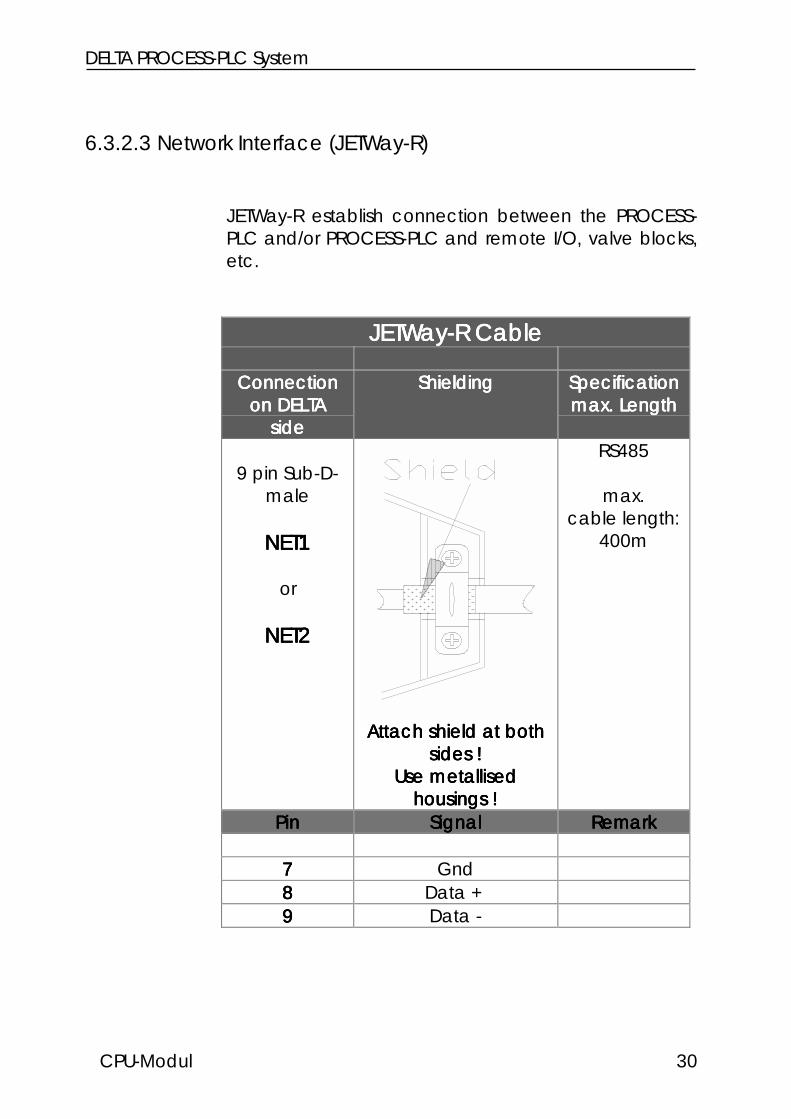
6.3.2.3 Network Interface (JETWay-R)
JETWay-R establish connection between the PROCESS-PLC and/or PROCESS-PLC and remote I/O, valve blocks,etc.
JETWay-R CableJETWay-R CableJETWay-R CableJETWay-R Cable
ConnectionConnectionConnectionConnectionon DELTAon DELTAon DELTAon DELTA
sidesidesideside
ShieldingShieldingShieldingShielding SpecificationSpecificationSpecificationSpecificationmax. Lengthmax. Lengthmax. Lengthmax. Length
9 pin Sub-D-male
NET1NET1NET1NET1
or
NET2NET2NET2NET2
Attach shield at bothAttach shield at bothAttach shield at bothAttach shield at bothsides !sides !sides !sides !
Use metallisedUse metallisedUse metallisedUse metallisedhousings !housings !housings !housings !
RS485
max.cable length:
400m
PinPinPinPin SignalSignalSignalSignal RemarkRemarkRemarkRemark
7777 Gnd8888 Data +9999 Data -

CPU Module
CPU Module 31
Note:Note:Note:Note:
If you make the cable yourself, the following minimumIf you make the cable yourself, the following minimumIf you make the cable yourself, the following minimumIf you make the cable yourself, the following minimumrequirements must be considered:requirements must be considered:requirements must be considered:requirements must be considered:
Number of wires:Number of wires:Number of wires:Number of wires: 3333Diameter:Diameter:Diameter:Diameter: 0,25mm0,25mm0,25mm0,25mm2222
Connection:Connection:Connection:Connection: Sub-D, metallisedSub-D, metallisedSub-D, metallisedSub-D, metallisedShielding:Shielding:Shielding:Shielding: total, not pairedtotal, not pairedtotal, not pairedtotal, not paired
The shield must on both sides have extensive contactThe shield must on both sides have extensive contactThe shield must on both sides have extensive contactThe shield must on both sides have extensive contactto the connector shells.to the connector shells.to the connector shells.to the connector shells.

DELTA PROCESS-PLC System
CPU-Modul 32
6.3.2.4 User Interface Connections
User Interface Cable (DK-422)User Interface Cable (DK-422)User Interface Cable (DK-422)User Interface Cable (DK-422)
PROCESS-PLCPROCESS-PLCPROCESS-PLCPROCESS-PLC User InterfaceUser InterfaceUser InterfaceUser Interface
15 pin Sub-D-male LCDLCDLCDLCD
RS422
max. cable length:400m
Attach shield at bothAttach shield at bothAttach shield at bothAttach shield at bothsides !sides !sides !sides !
Use metallisedUse metallisedUse metallisedUse metallisedhousings !housings !housings !housings !
15 pin Sub-D-male
PinPinPinPin SignalSignalSignalSignal PinPinPinPin
4 24 VDC 157 Gnd 12
10 SDB RDB 611 SDA RDA 712 RDB SDB 413 RDA SDA 5

CPU Module
CPU Module 33
Note:Note:Note:Note:
The prefabricated programming cable DK-422 can beThe prefabricated programming cable DK-422 can beThe prefabricated programming cable DK-422 can beThe prefabricated programming cable DK-422 can beobtained from JETTER.obtained from JETTER.obtained from JETTER.obtained from JETTER.If you make the cable yourself, the following minimumIf you make the cable yourself, the following minimumIf you make the cable yourself, the following minimumIf you make the cable yourself, the following minimumrequirements must be considered:requirements must be considered:requirements must be considered:requirements must be considered:
Number of wires:Number of wires:Number of wires:Number of wires: 6666Diameter:Diameter:Diameter:Diameter: 0,25mm0,25mm0,25mm0,25mm2222
Connection:Connection:Connection:Connection: Sub-D, metallisedSub-D, metallisedSub-D, metallisedSub-D, metallisedShielding:Shielding:Shielding:Shielding: total, not pairedtotal, not pairedtotal, not pairedtotal, not paired
The shield must on both sides have extensive contactThe shield must on both sides have extensive contactThe shield must on both sides have extensive contactThe shield must on both sides have extensive contactto the connector shells.to the connector shells.to the connector shells.to the connector shells.

DELTA PROCESS-PLC System
CPU-Modul 34
6.3.2.5 Process Monitoring Interface (RS232)
The process monitoring system JETVisu can beconnected via 2 different cables with the PROCESS-PLC.
JETLink Cable RS232 JETLink Cable RS232 JETLink Cable RS232 JETLink Cable RS232
ConnectionConnectionConnectionConnection JETVisuJETVisuJETVisuJETVisu
9 pin Sub-D-male PCPCPCPC
or
15 pin Sub-D-male LCDLCDLCDLCD
Attach shield at bothAttach shield at bothAttach shield at bothAttach shield at bothsides !sides !sides !sides !
Use metallisedUse metallisedUse metallisedUse metallisedhousings !housings !housings !housings !
RS232
max.cable length:
15m
PinPinPinPin SignalSignalSignalSignal PinPinPinPin
2222 TxD RxD 23333 RxD TxD 37777 Gnd 7
Pin 7 and 8and Pin 1, 4 and 6 have to be bridgedon the PC side (COM1, 2)
PossiblePossiblePossiblePossibleinterfaces:interfaces:interfaces:interfaces:
RS232RS232RS232RS232
orororor
JETWay-HJETWay-HJETWay-HJETWay-H
CPU Module
CPU Module 35
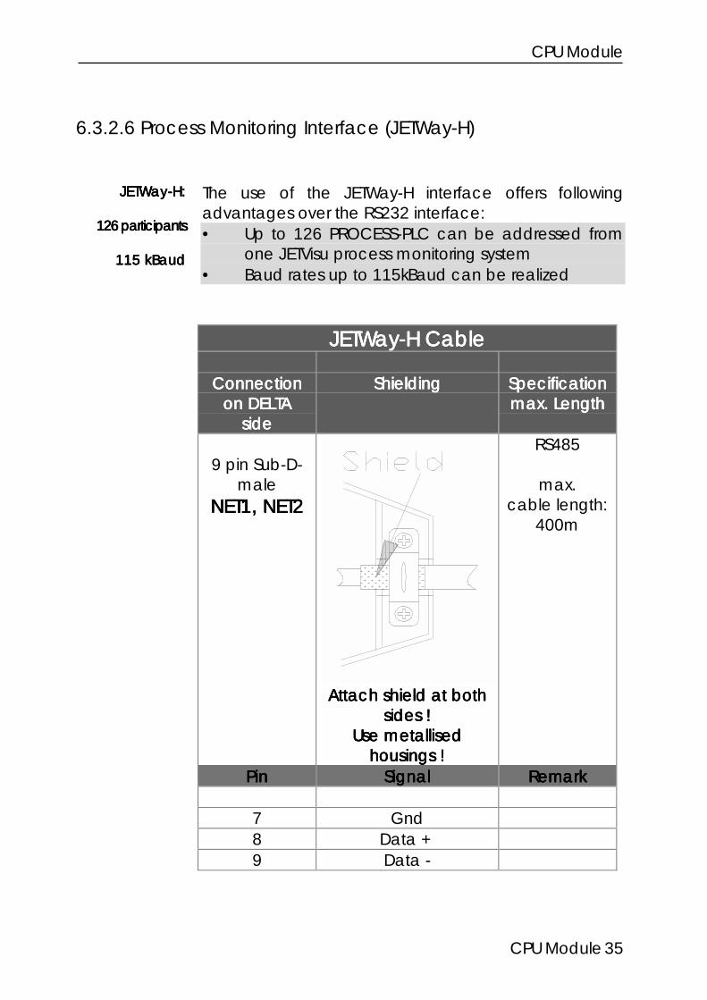
6.3.2.6 Process Monitoring Interface (JETWay-H)
The use of the JETWay-H interface offers followingadvantages over the RS232 interface:• Up to 126 PROCESS-PLC can be addressed from
one JETVisu process monitoring system• Baud rates up to 115kBaud can be realized
JETWay-H CableJETWay-H CableJETWay-H CableJETWay-H Cable
ConnectionConnectionConnectionConnectionon DELTAon DELTAon DELTAon DELTA
sidesidesideside
ShieldingShieldingShieldingShielding SpecificationSpecificationSpecificationSpecificationmax. Lengthmax. Lengthmax. Lengthmax. Length
9 pin Sub-D-male
NET1, NET2NET1, NET2NET1, NET2NET1, NET2
Attach shield at bothAttach shield at bothAttach shield at bothAttach shield at bothsides !sides !sides !sides !
Use metallisedUse metallisedUse metallisedUse metallisedhousings !housings !housings !housings !
RS485
max.cable length:
400m
PinPinPinPin SignalSignalSignalSignal RemarkRemarkRemarkRemark
7 Gnd8 Data +9 Data -
JETWay-H:JETWay-H:JETWay-H:JETWay-H:
126 participants126 participants126 participants126 participants
115 kBaud115 kBaud115 kBaud115 kBaud

DELTA PROCESS-PLC System
CPU-Modul 36
The JETWay-H PC-card has to be plugged into theVIADUKT or PC that executes JETVisu. All PROCESS-PLCwhich are monitored are connected with this PC-card.See Chapter 6.3.2.2 PC Programming Interface(JETWay-H)
JETWay-HJETWay-HJETWay-HJETWay-HPC-cardPC-cardPC-cardPC-card
necessarynecessarynecessarynecessary(plugged into(plugged into(plugged into(plugged into
VIADUKT)VIADUKT)VIADUKT)VIADUKT)

CPU Module
CPU Module 37
6.3.4 Digital Inputs6.3.4 Digital Inputs6.3.4 Digital Inputs6.3.4 Digital Inputs
16 terminals for digital inputs (24VDC) have beenprovided on the upper side of the controller housing.The 0V signal is connected to the control cabinetground (Gnd).
Technical Specifications Digital InputsTechnical Specifications Digital InputsTechnical Specifications Digital InputsTechnical Specifications Digital InputsNumber of Inputs 16Rated Input Voltage 24 VDCVoltage Range 15 .. 27 VInput Current approx. 8 mAInput Resistance 3,0 kΩInput Delay ca. 3msSignal Voltage ON min. 15 VSignal Voltage OFF max. 10 VPotential Isolation no
Input Numbering on theInput Numbering on theInput Numbering on theInput Numbering on theCPU ModuleCPU ModuleCPU ModuleCPU Module
InputInputInputInput NumberNumberNumberNumberInput 1 101Input 2 102... ...Input 16 116

DELTA PROCESS-PLC System
CPU-Modul 38
Figure 7: Digital input wiring
Figure 8: Internal circuit of the digital inputs

CPU Module
CPU Module 39
6.3.5 Digital Outputs6.3.5 Digital Outputs6.3.5 Digital Outputs6.3.5 Digital Outputs
16 terminals for digital outputs (24VDC) have beenprovided on the upper side of the controller housing.The 0V signal is connected to the control cabinetground (Gnd).
Technical Specifications digital OutputsTechnical Specifications digital OutputsTechnical Specifications digital OutputsTechnical Specifications digital OutputsNumber of Outputs 16Output Type Transistor, pnpRated Voltage 24 VDCVoltage Range 20 .. 30 VLoad Current max. 0,5 A / outputPotential isolation noProtection Circiut Overload, overvoltage,
overtemperatureProtection Inductive Loads yesSignal Voltage ON typ. VSupply - 0,5 V
Output Numbering on the CPU ModuleOutput Numbering on the CPU ModuleOutput Numbering on the CPU ModuleOutput Numbering on the CPU ModuleOutputOutputOutputOutput NumberNumberNumberNumber
Output 1 101Output 2 102... ...Output 16 116

DELTA PROCESS-PLC System
CPU-Modul 40
Figure 9: Digital output wiring
Figure 10: Internal circuit of the digital outputs

CPU Module
CPU Module 41
6.4 The LED
The LED indicate thestates of the digitalinputs and outputs aswell as the operatingsystem.
LED of the Digital InputsLED of the Digital InputsLED of the Digital InputsLED of the Digital Inputson the CPU Moduleon the CPU Moduleon the CPU Moduleon the CPU Module
LEDLEDLEDLED MeaningMeaningMeaningMeaningIN 1 lights at 24V...IN 16 -"-
Figure 11: LED of the CPU modules

DELTA PROCESS-PLC System
CPU-Modul 42
LED of the Digital OutputsLED of the Digital OutputsLED of the Digital OutputsLED of the Digital Outputson the CPU Moduleon the CPU Moduleon the CPU Moduleon the CPU Module
LEDLEDLEDLED MeaningMeaningMeaningMeaningOUT 1 Lights at 24V...OUT 16 -"-24 V External power supply of
the outputs OKERR2 Error of 1 or more output
drivers
LED of the Operating SystemLED of the Operating SystemLED of the Operating SystemLED of the Operating Systemon the CPU Moduleon the CPU Moduleon the CPU Moduleon the CPU Module
LEDLEDLEDLED BedeutungBedeutungBedeutungBedeutungRUN Operating system runsERR1 Operating system error
Error code in register 61477

CPU Module
CPU Module 43
6.5 The Switch
SwitchSwitchSwitchSwitchon the CPU Moduleon the CPU Moduleon the CPU Moduleon the CPU Module
PositionPositionPositionPosition MeaningMeaningMeaningMeaningRUN User program runsrunsrunsruns after
power-on of the controllerSTOP User program is stoppedstoppedstoppedstopped
after power-on of thecontroller
LOAD User program stopped.Operating system updateOperating system updateOperating system updateOperating system update
possible
Note:Note:Note:Note:
The switch is evaluated after power-on of the controller.The switch is evaluated after power-on of the controller.The switch is evaluated after power-on of the controller.The switch is evaluated after power-on of the controller.Switching during controller operation is not recognized.Switching during controller operation is not recognized.Switching during controller operation is not recognized.Switching during controller operation is not recognized.
Figure 12: Switch of the CPUmodule

DELTA PROCESS-PLC System
CPU-Modul 44
6.6 Addressing / Description Inputs, Outputs, Flags,Registers (Programming)
This chapter describes the access to the DELTA registers,inputs, outputs and flags.
The numbering of the registers, secial registers, flags,special flags, inputs and outputs is listed in tables.
Following instructions are used to access registers, flags,inputs and outputs.
REGISTER_LOAD, REG access to registers
FLAG access to flags
INPUT access to inputs
OUTPUT access to outputs
Example:Example:Example:Example:
REGISTER_LOAD [100 with 1234] ;loads register 100;with 1234
REG 100 = REG 300 + REG 200 ;adds the contents;of register 300;register 200 and;stores the result;in register 100
ProgrammingProgrammingProgrammingProgrammingof register,of register,of register,of register,
flags, inputs,flags, inputs,flags, inputs,flags, inputs,outputsoutputsoutputsoutputs

CPU Module
CPU Module 45
WHEN ;When flag 10FLAG 10 ;active continue
THEN ;task execution...
WHEN ;When input 101IN 101 ;active then
THEN ;set output 105OUT 105

DELTA PROCESS-PLC System
CPU-Modul 46
6.6.16.6.16.6.16.6.1 Addressing of the Digital Inputs and Outputs of a CPUAddressing of the Digital Inputs and Outputs of a CPUAddressing of the Digital Inputs and Outputs of a CPUAddressing of the Digital Inputs and Outputs of a CPUModuleModuleModuleModule
Input NumberingInput NumberingInput NumberingInput Numberingon the CPU Moduleon the CPU Moduleon the CPU Moduleon the CPU Module
InputInputInputInput NumberNumberNumberNumberInputs 1 101Inputs 2 102... ...Inputs 16 116
Output NumberingOutput NumberingOutput NumberingOutput Numberingon the CPU Moduleon the CPU Moduleon the CPU Moduleon the CPU Module
OutputOutputOutputOutput NumberNumberNumberNumberOutput 1 101Output 2 102... ...Output 16 116

CPU Module
CPU Module 47
6.6.2 Access of Flags6.6.2 Access of Flags6.6.2 Access of Flags6.6.2 Access of Flags
6.6.2.1 User Flags
Flag 1 to 2047 are available user flags. Some of thisflags are overlayed with registers 0 to 74. Thus flagranges can be accessed via registers. Bit operationscan be realized with the W-AND, W-OR and W-XORinstructions.
Overlay of Registers and FlagsOverlay of Registers and FlagsOverlay of Registers and FlagsOverlay of Registers and Flags
RegisterRegisterRegisterRegister FlagFlagFlagFlag RemarkRemarkRemarkRemark1 to 255 free
0 to 74 256 to 2047 OverlayOverlayOverlayOverlay2048 to 2303 Special flags
Example:Example:Example:Example:
Flag 1 to 2047Flag 1 to 2047Flag 1 to 2047Flag 1 to 2047are availableare availableare availableare available
user flagsuser flagsuser flagsuser flags
Overlay User Flags - RegistersOverlay User Flags - RegistersOverlay User Flags - RegistersOverlay User Flags - RegistersExemplary for Register 0Exemplary for Register 0Exemplary for Register 0Exemplary for Register 0
Bitno 0 1 2 3 4 ... 21 22 23Flag 256 257 258 259 260 ... 277 278 279

DELTA PROCESS-PLC System
CPU-Modul 48
Programming with FlagsProgramming with FlagsProgramming with FlagsProgramming with Flags
Example 1:Example 1:Example 1:Example 1:
The execution of a process is to start, if the start button ispressed and the automatic mode is released by bysetting of the corresponding flag (for example in another task).
WHENIN iStartKeyFLAG fAutomatic
THEN...
Example 2:Example 2:Example 2:Example 2:
A flag in the main task starts execution of a second task,the automatic task.
TASK tMainTask ----------------------...IF
IN iStartKeyTHENFLAG fAutomatic
...GOTO tMainTask
TASK tAutomatic ----------------------WHEN
Flag fAutomaticTHEN
..GOTO tAutomatic

CPU Module
CPU Module 49
6.6.2.2 Special Flags
The PROCESS-PLC operating system provides variousspecial flags that allow control or modification offunctions. The following table gives an overview of thespecial flags, structured by functions and with the cross-reference to chapters that describe the functions morecomprehensively.
Note:Note:Note:Note:
Basically a set flag means the activation of theBasically a set flag means the activation of theBasically a set flag means the activation of theBasically a set flag means the activation of thefunction. Exceptions will be specially referred to.function. Exceptions will be specially referred to.function. Exceptions will be specially referred to.function. Exceptions will be specially referred to.

DELTA PROCESS-PLC System
CPU-Modul 50
Special FlagsSpecial FlagsSpecial FlagsSpecial FlagsUser InterfaceUser InterfaceUser InterfaceUser Interface
Keys / LEDKeys / LEDKeys / LEDKeys / LED
Control of the User Interface LEDControl of the User Interface LEDControl of the User Interface LEDControl of the User Interface LED
LED, KeyLED, KeyLED, KeyLED, Key SpecialSpecialSpecialSpecialFlagFlagFlagFlag
LED, KeyLED, KeyLED, KeyLED, Key SpecialSpecialSpecialSpecialFlagFlagFlagFlag
LED F1 2224 LED F7 2230LED F2 2225 LED F8 2231LED F3 2226 LED F9 2232LED F4 2227 LED F10 2233LED F5 2228 LED F11 2234LED F6 2229 LED F12 2235
Query of the User Unterface KeysQuery of the User Unterface KeysQuery of the User Unterface KeysQuery of the User Unterface Keys
KeyKeyKeyKey SpecialSpecialSpecialSpecialFlagFlagFlagFlag
SHIFT +SHIFT +SHIFT +SHIFT +KeyKeyKeyKey
SpecialSpecialSpecialSpecialFlagFlagFlagFlag
Function KeysFunction KeysFunction KeysFunction Keys
F1 2201 SHIFT-F1 2181F2 2202 SHIFT-F2 2182F3 2203 SHIFT-F3 2183F4 2204 SHIFT-F4 2184F5 2205 SHIFT-F5 2185F6 2206 SHIFT-F6 2186F7 2207 SHIFT-F7 2187F8 2208 SHIFT-F8 2188F9 2209 SHIFT-F9 2189F10 2210 SHIFT-F10 2190F11 2211 SHIFT-F11 2191F12 2212 SHIFT-F12 2192

CPU Module
CPU Module 51
Special Function KeysSpecial Function KeysSpecial Function KeysSpecial Function Keys
<- 2214 SHIFT <- 2193-> 2213 SHIFT -> 2194C 2218 SHIFT C 2198ENTER 2219 SHIFT ENTER 2199SHIFT 2200= 2217 SHIFT = 2197. 2222 SHIFT . 2223- 2220 SHIFT - 2221R 2215 SHIFT R 2195I/O 2216 SHIFT I/O 2196
Numerical KeysNumerical KeysNumerical KeysNumerical Keys
0 2160 SHIFT 0 21701 2161 SHIFT 1 21712 2162 SHIFT 2 21723 2163 SHIFT 3 21734 2164 SHIFT 4 21745 2165 SHIFT 5 21756 2166 SHIFT 6 21767 2167 SHIFT 7 21778 2168 SHIFT 8 21789 2169 SHIFT 9 2179
Special FlagsSpecial FlagsSpecial FlagsSpecial Flags
SpecialSpecialSpecialSpecialFlagFlagFlagFlag
FunctionFunctionFunctionFunction Cross-Cross-Cross-Cross-ReferenceReferenceReferenceReference
(Error) Messages via Special Flags(Error) Messages via Special Flags(Error) Messages via Special Flags(Error) Messages via Special Flags
2104 timeout during last slaveaccess

DELTA PROCESS-PLC System
CPU-Modul 52
2105 at minimum 1 timeout sincereset during slave registeraccess
2110 timeout during last networkaccess (JETWay)
2111 at minimum 1 timeout sincereset during network access
2136 invalid label for GOTO or CALLindirect
2137 current instruction wouldcause stack overflow; taskwas breaked
2138 current instruction wouldcause stack underflow; taskwas breaked
2139 no user program or CRC error2140 OP code error2144 output error message2145 real time clock identified2146 battery real time clock OK2147 battery register RAM almost
empty
Task ControlTask ControlTask ControlTask Control
2056 taskswitch after (reg 61804)ms
2057 taskswitch if GOTO instruction2058 taskswitch if not fullfilled IF
instruction2112 PC and user interface after
each task
Network Control with Special FlagsNetwork Control with Special FlagsNetwork Control with Special FlagsNetwork Control with Special Flags
2152 multimaster mode network 12153 multimaster mode network 2

CPU Module
CPU Module 53
ArithmeticArithmeticArithmeticArithmetic
2048 use real instead of integer fordivision
0 = on
2049 real mode
User Interface ControlUser Interface ControlUser Interface ControlUser Interface Control
2051 USER_INPUT instruction is active2053 USER_INPUT breaked by
timeout
User Interface RestrictionsUser Interface RestrictionsUser Interface RestrictionsUser Interface Restrictions
2052 user interface input locked2054 (ENTER) switches not to
monitor mode2096 no register display 0 = locked2097 no flag display 0 = locked2098 no output display 0 = locked2099 no input display 0 = locked2100 no register input 0 = locked2101 no flag input 0 = locked2102 no output input 0 = locked2103 no continuous input display

DELTA PROCESS-PLC System
CPU-Modul 54
6.6.3. Register Description (The DELTA Data)6.6.3. Register Description (The DELTA Data)6.6.3. Register Description (The DELTA Data)6.6.3. Register Description (The DELTA Data)
6.6.3.1 User Registers
20480 user register are available in the register range of0 to 20479. They serve as working registers, buffers forvarious variables, parameters, etc.
The registers have a width of 24 bit and a value rangeof -8,388,608 to +8,388,607.
For example registers can be loaded with theREGISTER_LOAD instruction.
User registers:User registers:User registers:User registers:0 to 204790 to 204790 to 204790 to 20479
Note:Note:Note:Note:
The content of the 20480 user registers remains afterThe content of the 20480 user registers remains afterThe content of the 20480 user registers remains afterThe content of the 20480 user registers remains afterpower-off of the controller.power-off of the controller.power-off of the controller.power-off of the controller.
Figure 13: REGISTER_LOAD withsymbolic parameters
Figure 14:REGISTER_LOAD withnumerical parameters

CPU Module
CPU Module 55
Programming with RegistersProgramming with RegistersProgramming with RegistersProgramming with Registers
The instruction
REGISTER_LOAD [ x with a]
loads values from one register into another.
Description:Description:Description:Description:
x x x x defines the number of the register into which thenumber aaaa is to be written.
Indirect and Double Indirect AdressingIndirect and Double Indirect AdressingIndirect and Double Indirect AdressingIndirect and Double Indirect Adressing
The xxxx and the aaaa of the example above need not to be anumber. They can also be replaced by a register(indirect addressing). The indirect level can be obtainedby pressing the (SPACE) key. In this case RRRR is set beforethe register number.The value aaaa is written into the register with the number yyyy ifR(y)R(y)R(y)R(y) is used instead of xxxx.If R(b)R(b)R(b)R(b) is used instead of aaaa then not the value itself but thecontent of the register with the number bbbb is written intothe register which number is specified by R(y).R(y).R(y).R(y).
If you now enter RRRRRRRR (2 times space key) and then thenumber (b)(b)(b)(b) instead of aaaa
REGISTER_LOAD [ x with RR(b)]
the following happens:
• first the content of the register with the number bbbb isread
• this value is now used as register numberregister numberregister numberregister number; from theregister with this number the content is read and storedinto register xxxx
Call-up inCall-up inCall-up inCall-up inSYMPAS withSYMPAS withSYMPAS withSYMPAS with
(L) (R)
Indirect levelIndirect levelIndirect levelIndirect levelwithwithwithwith
(SPACE) key key key key1 time, 2 times1 time, 2 times1 time, 2 times1 time, 2 times

DELTA PROCESS-PLC System
CPU-Modul 56
Example:Example:Example:Example:
1) Load a number into a register
REGISTER_LOAD [ rNewPosition with 1280]
The value 1280 is stored into register rNewPosition.
2) Copy one register into another
REGISTER_LOAD [ rVoltage with R(rVoltage1)]
The value of register rVoltage1 is copied into registerrVoltage.
3a) Loading by using double indirect addressing
REGISTER_LOAD [rVoltage with RR(rU_Pointer)]
The value which is in the register with the number that iscontent of register rU_Pointer is stored into registerrVoltage
Figure 15: The indirect levels R and RR canbe entered with (SPACE) or (CTRL) (R)
Indirect andIndirect andIndirect andIndirect anddoubledoubledoubledoubleindirectindirectindirectindirect
addressing ofaddressing ofaddressing ofaddressing ofregistersregistersregistersregisters

CPU Module
CPU Module 57
3b) Example of double indirect addressing:
RegistersRegistersRegistersRegisters ValueValueValueValueREG 64 111REG 111 70035REG 150 11REG 11 any
following instruction is executed with this registerassignment:
LADE_REGISTER [R(150) mit RR(64)]
Following register values result:
Register 64 = 111 (value remains)Register 111 = 70035 (value remains)Register 150 = 11 (value remains)Register 11 = R150 = RR64 = R111 = 70035
Diagram:Diagram:Diagram:Diagram:
R(150) RR(64)
REG 150 REG 6411 111
REG 11 REG 111any 70035
70035is copiedintoREG 11

DELTA PROCESS-PLC System
CPU-Modul 58
Calculating with RegistersCalculating with RegistersCalculating with RegistersCalculating with Registers
Instructions for calculating:
REG <RegNo>
REGZERO <RegNo>
REGDEC <RegNo>
REGINC <RegNo>
This 4 instructions allow indirect addressing. For instanceRegNo can be R100. This means the instruction effectsthe content of the register that is specified by the numberin REG 100.
Figure 37: Simple Example on Register Arithmetic

CPU Module
CPU Module 59
REG
This instruction directly accesses the content of a registerand is equivalent to a variable. In an output instruction avalue is assigned to the register that stands at the left sideof the equal sign. In an input condition the registercontent is read. Accesses to registers at the right side ofthe equal sign always read the register contents.
Example:Example:Example:Example:
1) THENREG 1=REG 105*25
This example shows an assignment (output instructionassignment (output instructionassignment (output instructionassignment (output instructionintroduced by THEN). Thereby register 105 is read and itscontent is multiplied with 25. The result of this operation isstored into register 1. The content of register 105 remainsunchanged.
2) WHENREG 1=REG 105*25
THEN
In this case the expression REG 1 = REG 105 * 25 isnot placed in an output instruction but in an inputinputinputinputconditionconditionconditioncondition. Therefore the value of register 1 is notmodified but compared with the product of REG 105 *25.
Call-up inCall-up inCall-up inCall-up inSYMPAS withSYMPAS withSYMPAS withSYMPAS with
(R) (E)
Example for anExample for anExample for anExample for anoutputoutputoutputoutput
instructioninstructioninstructioninstruction
Example for anExample for anExample for anExample for aninput conditioninput conditioninput conditioninput condition

DELTA PROCESS-PLC System
CPU-Modul 60
The REGZERO condition sets a register to 0 or queries if aregister is 0:
REGZERO <RegNo>
This instruction has following meaning used in an inputcondition (after IF or WHEN).
Example:Example:Example:Example:
IF IFREGZERO 49 REG 49
THEN =0
THEN
Both program parts have the same function. On the rightthe comparison is executed as common arithmeticcomparison; on the left the REGZERO instruction is used(advantages: faster execution, less code).
The instructions
REGDEC REGINC
This registers are used to increment or decrement aregister by 1. These instructions are often used in loops,for increment or decrement of counters and pointers.
Example:Example:Example:Example:
1a) 1b)THEN THENREGDEC 100 REG 100
=REG 100-1
Both program parts have the same function. Bothdecrement the content of register 100 by 1.
Call-up inCall-up inCall-up inCall-up inSYMPAS withSYMPAS withSYMPAS withSYMPAS with
(R) (N)
Call-up inCall-up inCall-up inCall-up inSYMPAS withSYMPAS withSYMPAS withSYMPAS with
(R) (D)resp.resp.resp.resp.
(R) (I)

CPU Module
CPU Module 61
2a) 2b)THEN THENREGINC 88 REG 88
=REG 88+1
Also here both program parts have the same effect.Register 88 is incremented by 1.
3a) REGISTER_LOAD [ 1 with 10]LABEL 55
...REGDEC 1
IFREGZERO 1
THENELSEGOTO 55
THEN
A loop can be realized this way that executes a certainnumber of loops. The counter register is decremeted by1 each loop and compared with 0. If it is 0 nothing isdone at the first THEN and the program flow continues tothe second THEN. If it is not yet 0 the ELSE instructionbranches to the loop top.
3b) REGISTER_LOAD [ 1 with 10]LABEL 55
...REGDEC 1
IFREG 1 ;≠≠≠≠0 -> true
THEN ;=0 -> falseGOTO 55
THEN
Both examplesBoth examplesBoth examplesBoth exampleshave the samehave the samehave the samehave the same
functionfunctionfunctionfunction
Example:Example:Example:Example:looplooplooploop
DELTA PROCESS-PLC System
CPU-Modul 62
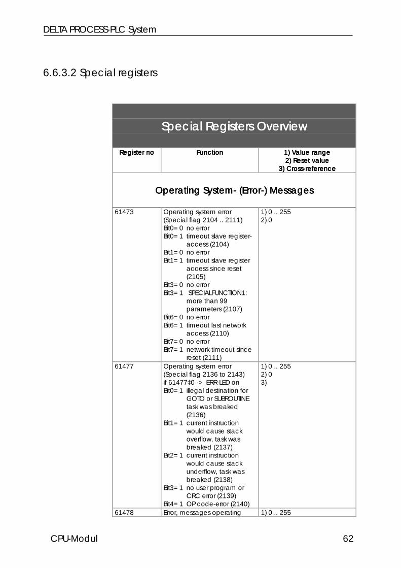
6.6.3.2 Special registers
Special Registers OverviewSpecial Registers OverviewSpecial Registers OverviewSpecial Registers Overview
Register noRegister noRegister noRegister no FunctionFunctionFunctionFunction 1) Value range1) Value range1) Value range1) Value range2) Reset value2) Reset value2) Reset value2) Reset value
3) Cross-reference3) Cross-reference3) Cross-reference3) Cross-reference
Operating System- (Error-) MessagesOperating System- (Error-) MessagesOperating System- (Error-) MessagesOperating System- (Error-) Messages
61473 Operating system error(Special flag 2104 .. 2111)Bit0=0 no errorBit0=1 timeout slave register-
access (2104)Bit1=0 no errorBit1=1 timeout slave register
access since reset(2105)
Bit3=0 no errorBit3=1 SPECIALFUNCTION1:
more than 99parameters (2107)
Bit6=0 no errorBit6=1 timeout last network
access (2110)Bit7=0 no errorBit7=1 network-timeout since
reset (2111)
1) 0 .. 2552) 0
61477 Operating system error(Special flag 2136 to 2143)if 61477‡0 -> ERR-LED onBit0=1 illegal destination for
GOTO or SUBROUTINEtask was breaked(2136)
Bit1=1 current instructionwould cause stackoverflow, task wasbreaked (2137)
Bit2=1 current instructionwould cause stackunderflow, task wasbreaked (2138)
Bit3=1 no user program orCRC error (2139)
Bit4=1 OP code-error (2140)
1) 0 .. 2552) 03)
61478 Error, messages operating 1) 0 .. 255

CPU Module
CPU Module 63
systemBit0=1 Error digital output
(2144)Bit1=1 real time clock
identified (2145)Bit2=1 battery real time clock
Ok (2146)Bit3=1 battery register RAM
soon empty (2147)
2) 0
61530 Task number of OPC error 1) 0 .. 2552) not defined
61952 User program runtime inseconds
1) -8388608 .. 83886072) 03)
61953 Controller run time in seconds 1) -8388608 .. 83886072) 03)
61954 Controller runtime in time baseunits
1) -8388608 .. 83886072) 0
61956 Controller runtime since resetin ms
1) -8388608 .. 83886072) 03)
62977 Operating system version *100
1) 0 .. 655352) 03)
Task ControlTask ControlTask ControlTask Control
61449 Priority task 1) 0 .. 2552) 255 = no priority task3)
61467 Taskswitch conditions(Special flags 2056 to 2063)Taskswitch always ifo DELAYo USER_INPUTo WHEN (not fullfilled)and also ifo Flag 2056 AND
taskswitch timeout(61804)
o Flag 2057 AND GOTOo Flag 2058 AND IF (not
fullfilled)Bit0 = flag 2056Bit0=0 no taskswitch if timeoutBit0=1 taskswitch if timeoutBit1 = flag 2057Bit1=0 no taskswitch if GOTOBit1=1 taskswitch if GOTOBit2 = flag 2058Bit2=0 no taskswitch if IF (not
fullfilled)Bit2=1 taskswitch if IF (not
fullfilled)
1) 0 .. 2552) 33)

DELTA PROCESS-PLC System
CPU-Modul 64
61474 Multitasking control(Special flag 2112 .. 2119)Bit0=0 SYMPAS, LCD beforeTASK0 (default)Bit0=1 SYMPAS, LCD before
each Task (2112)Bit5=0 N-SEND-REGISTER,
N-GET-REGISTER areinterrupted
Bit5=1 N-SEND-REGISTER,N-GET-REGISTER are notinterrupted (2117)(default)
1) 0 .. 2552)
61531 ..61562
Task status:255 = Task runs254 = DELAY253 = USER_INPUT250 = WHEN_MAX1 = TASKBREAK0 = breaked
1) 0 .. 2552) Status3) SYMPAS: index window
61610 Highest task number 1) 0 .. 2552) 03)
61773 Minimum cycle time (ms) 1) 0 .. 655352) 0
61774 Maximum cycle time (ms) 1) 0 .. 655352) 0
61777 Cycle time of all task (ms) 1) 0 .. 655352) 0
61804 Task timeout time (ms) 1) 0 .. 2552) 0
User Interface Control (LCD-Display)User Interface Control (LCD-Display)User Interface Control (LCD-Display)User Interface Control (LCD-Display)
61448 Display language, 0 =german, 1 = english
1) 0 .. 2552) Depends on the userprogram3)
61451 Field width for floating pointregister display
1) 0 .. 2552) 83)
61452 Number of decimal places 1) 0 .. 2552) 43)
61453 Field width for integer display 1) 0 .. 2552) 13)
61454 Flush left number displayFlag 2055=0 leading blanksFlag 2055=1 leading zeros
1) 0 .. 2552) 03)
61455 Field width USER_INPUT 1) 0 .. 2552) 83)
61461 'Delete line' character 1) 0 .. 255

CPU Module
CPU Module 65
2) 363)
61462 'Clear display' character 1) 0 .. 2552) 953)
61472 Restrictions for monitorfunctions0 = disable, 1 = enable(Flag 2096 .. 2103)Bit0=0 R, I/O key without
register number inputBit0=1 R, I/O key with register
number inputBit1=0 R, I/O key without flag
number inputBit1=1 R, I/O key with flag
number inputBit2=0 R, I/O key without
output number inputBit2=1 R, I/O key with output
number inputBit3=0 R, I/O key without input
number inputBit3=1 R, I/O key with output
number inputBit4=0 = key changes no
register contentsBit4=1 = key changes register
contentsBit5=0 = key changes no
flagsBit5=1 = key changes flagsBit6=0 = key changes no
outputsBit6=1 = key changes outputsBit7=0 = key does not access
to inputsBit7=1 = key does access to
inputs
1) 0 .. 2552) 03)
61480 ..61487
User interface keys(Special flags 2169 .. 2223)
1) 0 .. 2552) Key status3) See special registers
61488 ..61489
LED user interfaces(Special flags)
1) 0 .. 2552) 03) See special registers
61648 Indirect cursor position cp=0for DISPLAY_TEXT undDISPLAY_REG
1) 0 .. 2552) 03)
61649 Indirect cursor position cp=0for USER_INPUT
1) 0 .. 2552) 03)
61653 Display time for monitorfunctions (s)
1) 0 .. 655352) 33)
61683 Text selection forDISPLAY_TEXT_2
1) 0 .. 2552) 0
DELTA PROCESS-PLC System
CPU-Modul 66
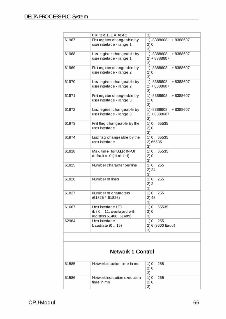
0 = text 1, 1 = text 2 3)61967 First register changeable by
user interface - range 11) -8388608 .. +83886072) 03)
61968 Last register changeable byuser interface - range 1
1) -8388608 .. +83886072) +83886073)
61969 First register changeable byuser interface - range 2
1) -8388608 .. +83886072) 03)
61970 Last register changeable byuser interface - range 2
1) -8388608 .. +83886072) +83886073)
61971 First register changeable byuser interface - range 3
1) -8388608 .. +83886072) 03)
61972 Last register changeable byuser interface - range 3
1) -8388608 .. +83886072) +83886073)
61973 First flag changeable by theuser interface
1) 0 .. 655352) 03)
61974 Last flag changeable by theuser interface
1) 0 .. 655352) 655353)
61818 Max. time for USER_INPUTdefault = 0 (disabled)
1) 0 .. 655352) 03)
61825 Number character per line 1) 0 .. 2552) 243)
61826 Number of lines 1) 0 .. 2552) 23)
61827 Number of characters(61825 * 61826)
1) 0 .. 2552) 483)
61667 User interface LED(bit 0 .. 11, overlayed withregisters 61488, 61489)
1) 0 .. 655352) 03)
62984 User interfacebaudrate (0 .. 15)
1) 0 .. 2552) 6 (9600 Baud)3)
Network 1 ControlNetwork 1 ControlNetwork 1 ControlNetwork 1 Control
61585 Network reaction time in ms 1) 0 .. 2552) 03)
61586 Network instrcution executiontime in ms
1) 0 .. 2552) 03)

CPU Module
CPU Module 67
61588 Timeout time network 1 1) 0 .. 2552)3)
61589 Indirect network addressing 1) 0 .. 2552) 03)
61828 50000er offset for inputs 1) 0 .. 655352) 1003)
61829 50000er offset for outputs 1) 0 .. 655352) 2003)
61830 50000er offset for flags 1) 0 .. 655352) 03)
61831 50000er offset for registers 1) 0 .. 655352) 03)
61955 Number checksum errorsnetwork receiving
1) -8388608 .. +83886072) 03)
62995 Network 1 number 1) -8388608 .. +83886072) Register 632413)
62996 Baud rate Network 10 1501 3002 6003 12004 24005 48006 9600 default7 192008 384009 5760010 7680011..14 115200
1) 0 .. 2552) Register 632423)
63242 Baud rate Network EEPROM63241 Network number network 1 at
switch-on (EEPROM)1) 0 .. 2552) last number3)
Free Prog. Interface via LCD ConnectorFree Prog. Interface via LCD ConnectorFree Prog. Interface via LCD ConnectorFree Prog. Interface via LCD Connectorinstead of User Interface
62155 Reception buffer level 1) 0 .. 2552) 03)
62156 Transmission buffer level 1) 0 .. 2552) 03)
62984 Baud rate0 1501 3002 600
1) 0 .. 2552) 63)

DELTA PROCESS-PLC System
CPU-Modul 68
3 12004 24005 48006 9600 default7 192008 38400
63002 Interface stateBit3=1 character lost during
reception, parity error,stop bit error
Bit4=1 receiving bufferoverflow
1) 0 .. 2562) State3)
63003 ConfigurationBit0 0=PRIM, 1=LCDBit1 reservedBit2 0=1, 1=2 stop bitBit3 0=7, 1=8 bit/charBit4,5 00=no parity
01=not allowed10=odd11=even
Bit7,6 00=RS23201=RS485 (4 wire)10=RS42211=RS485 (2 wire)
Default: PRIM, RS232,8N1,9600
1) 0 .. 2552)3)
63004 Transmission buffer 1) 0 .. 2552)3)
63005 Reception buffer - accessremoves character
1) 0 .. 2552)3)
63006 Reception buffer - accessdoed not remove character
1) 0 .. 2552)3)
Network 2 Control / Free Prog. InterfaceNetwork 2 Control / Free Prog. InterfaceNetwork 2 Control / Free Prog. InterfaceNetwork 2 Control / Free Prog. Interface
61499 Receiving buffer level 1) 0 .. 1282) 03)
61502 Tansmission buffer level 1) 0 .. 1282) 03)
61508 Interface stateBit0=1 one or more
charecters lost duringreceiving
Bit1=1 stop bit errorBit2=1 parity errorBit3=1 bit0 to 2 is or was not 0Bit4=1 receiving buffer
overflow
1) 0 .. 2562) State3)

CPU Module
CPU Module 69
Bit5=1 transmission bufferoverflow
61511 Timeout time network 2 1) 0 .. 2552)3)
62989 ConfigurationBit0 0=PRIM, 1=net2Bit1 reservedBit2 0=1, 1=2 stop bitBit3 0=7, 1=8 bit/charBit4,5 00=no parity
01=not allowed10=odd11=even
Bit7,6 00=RS23201=RS485 (4 wire)10=RS42211=RS485 (2 wire)
Default: PRIM, RS232,8N1,9600
1) 0 .. 2552)3)
62990 Baud rate0 1501 3002 6003 12004 24005 48006 9600 default7 192008 384009 5760010 7680011..14 115200
1) 0 .. 2552) 63)
62991 Network number network 2 1) 0 .. 2552) 23)
62992 Transmission buffer 1) 0 .. 2552) 03)
62993 Receiving buffer withcharacter removing
1) 0 .. 2552) 03)
62994 Receiving buffer withoutcharacter removing
1) 0 .. 2552) 03)
Programming Interface Control (PC)Programming Interface Control (PC)Programming Interface Control (PC)Programming Interface Control (PC)
62983 Baud rate programminginterface (0..15)0 1501 3002 6003 12004 2400
1) 0 .. 2552) Register 632383)

DELTA PROCESS-PLC System
CPU-Modul 70
5 48006 9600 default7 192008 384009 5760010 7680011..14 115200initialized by 63238 at power-on
63238 Baud rate pointerprogramming interface(EEPROM)
1) 0 .. 2552) EEPROM3)
User Programm StateUser Programm StateUser Programm StateUser Programm State
61440 Bit0=0 Program stoppedBit0=1 Program runs
1) 0 .. 2552) 13)
61529 Switch position at power-on0=Stop, 2=Run, 1=Load
1) 0 .. 2552) Switch position power-on3)
62976 Current switch position0=Stop, 2=Run, 1=Load
1) 0 .. 2552) Switch position3)
Time RegisterTime RegisterTime RegisterTime Register
61645 Number of time registers 1) 0 .. 2552) Number time registers3)
61708 ..61739
Task time registers 1) 0 .. 655352) 0
61806 User time base in ms 1) 0 .. 655352)3)
61848 Time base for START-TIMER,TIMER-END?
1) 0 .. 655352)3)
Real Time ClockReal Time ClockReal Time ClockReal Time Clock
62912 ..62919
RTC buffer - no transfer to RTC 1) 0 .. 2552)3)
62920 ..62927
RTC direct, transfer of allregisters
1) 0 .. 2552)3)
62912,62920
Seconds 1) 0 .. 2552) current time3)
62913,62921
Minutes 1) 0 .. 2552) current time

CPU Module
CPU Module 71
3)62914,62922
Hours 1) 0 .. 2552) current time3)
62915,62923
24 hours format 0,12 hours format:0=am, 128=pm
1) 0 .. 2552) last setting3)
62916,62924
Day of week, 1=Sunday 1) 0 .. 2552) last setting3)
62917,62925
Day 1) 0 .. 2552) current date3)
62918,62926
Month 1) 0 .. 2552) current date3)
62919,62927
Year 1) 0 .. 2552) current date3)
63240 Configuration (EEPROM)Bit0=1 Summer-/Winter time
activatedBit1=0 am/pm format
1) 0 .. 2552)3)
Floating Point RegistersFloating Point RegistersFloating Point RegistersFloating Point Registers
62208 ..62463
Value range: -1015 to +1015 1) -1015 bis +1015
2) last value3)
Controller Module AccessController Module AccessController Module AccessController Module AccessValues valid if 2104/2105=1
62150 Controller module accesserror:slot number minus 1
1) 0 .. 2552) 03)
62151 Axis module access error:axis number minus 1
1) 0 .. 2552) 03)
62152 Controller module accesserror:register number
1) 0 .. 655352) 03)
General RegistersGeneral RegistersGeneral RegistersGeneral Registers
61684 Slot and modules bit code 1) 0 .. 2552) Slot state3)
62985 Single channel counter atINPUT2
1) -8388608 .. +83886072) 03)

DELTA PROCESS-PLC System
CPU-Modul 72
24 Combined Inputs24 Combined Inputs24 Combined Inputs24 Combined Inputs
62592 Inputs 101 .. 124 1) -8388608 .. +838860762593 Inputs 109 .. 132 2) Input state62594 Inputs 117 .. 140 3)62595 Inputs 125 .. 14862596 Inputs 133 .. 15662597 Inputs 141 .. 16462598 Inputs 149 .. 16462599 Inputs 157 .. 16462600 Inputs 201 .. 22462601 Inputs 209 .. 23262602 Inputs 217 .. 24062603 Inputs 225 ..24862604 Inputs 233 .. 25662605 Inputs 241 .. 26462606 Inputs 249 .. 26462607 Inputs 257 .. 26462608 Inputs 301 .. 32462609 Inputs 309 .. 33262610 Inputs 317 .. 34062611 Inputs 325 .. 34862612 Inputs 333 .. 35662613 Inputs 341 .. 36462614 Inputs 349 .. 36462615 Inputs 357 .. 36462616 Inputs 401 .. 42462617 Inputs 409 .. 43262618 Inputs 417 .. 44062619 Inputs 425 .. 44862620 Inputs 433 .. 45662621 Inputs 441 .. 46462622 Inputs 449 .. 46462623 Inputs 457 .. 46462624 Inputs 501 .. 52462625 Inputs 509 .. 53262626 Inputs 517 .. 54062627 Inputs 525 .. 54862628 Inputs 533 .. 55662629 Inputs 541 .. 56462630 Inputs 549 .. 56462631 Inputs 557 .. 56462632 Inputs 601 .. 62462633 Inputs 609 .. 63262634 Inputs 617 .. 64062635 Inputs 625 .. 64862636 Inputs 633 .. 65662637 Inputs 641 .. 66462638 Inputs 649 .. 66462639 Inputs 657 .. 66462640 Inputs 701 .. 72462641 Inputs 709 .. 73262642 Inputs 717 .. 740

CPU Module
CPU Module 73
62643 Inputs 725 .. 74862644 Inputs 733 .. 75662645 Inputs 741 .. 76462646 Inputs 749 .. 76462647 Inputs 757 .. 76462648 Inputs 801 .. 82462649 Inputs 809 .. 83262650 Inputs 817 .. 84062651 Inputs 825 .. 84862652 Inputs 833 .. 85662653 Inputs 841 .. 86462654 Inputs 849 .. 86462655 Inputs 857 .. 864
16 Combined Inputs16 Combined Inputs16 Combined Inputs16 Combined Inputs
62528 Inputs 101 .. 116 1) 0 .. 6553562529 Inputs 109 .. 124 2) Input state62530 Inputs 117 .. 132 3)62531 Inputs 125 .. 14062532 Inputs 133 .. 14862533 Inputs 141 .. 15662534 Inputs 149 .. 16462535 Inputs 157 .. 16462536 Inputs 201 .. 21662537 Inputs 209 .. 22462538 Inputs 217 .. 23262539 Inputs 225 .. 24062540 Inputs 233 .. 24862541 Inputs 241 .. 25662542 Inputs 249 .. 26462543 Inputs 257 .. 26462544 Inputs 301 .. 31662545 Inputs 309 .. 32462546 Inputs 317 .. 33262547 Inputs 325 .. 34062548 Inputs 333 .. 34862549 Inputs 341 .. 35662550 Inputs 349 .. 36462551 Inputs 357 .. 36462552 Inputs 401 .. 41662553 Inputs 409 .. 42462554 Inputs 417 .. 43262555 Inputs 425 .. 44062556 Inputs 433 .. 44862557 Inputs 441 .. 45662558 Inputs 449 .. 46462559 Inputs 457 .. 46462560 Inputs 501 .. 51662561 Inputs 509 .. 52462562 Inputs 517 .. 53262563 Inputs 525 .. 540

DELTA PROCESS-PLC System
CPU-Modul 74
62564 Inputs 533 .. 54862565 Inputs 541 .. 55662566 Inputs 549 .. 56462567 Inputs 557 .. 56462568 Inputs 601 .. 61662569 Inputs 609 .. 62462570 Inputs 617 .. 63262571 Inputs 625 .. 64062572 Inputs 633 .. 64862573 Inputs 641 .. 65662574 Inputs 649 .. 66462575 Inputs 657 .. 66462576 Inputs 701 .. 71662577 Inputs 709 .. 72462578 Inputs 717 .. 73262579 Inputs 725 .. 74062580 Inputs 733 .. 74862581 Inputs 741 .. 75662582 Inputs 749 .. 76462583 Inputs 757 .. 76462584 Inputs 801 .. 81662585 Inputs 809 .. 82462586 Inputs 817 .. 83262587 Inputs 825 .. 84062588 Inputs 833 .. 84862589 Inputs 841 .. 85662590 Inputs 849 .. 86462591 Inputs 857 .. 864
8 Combined Inputs8 Combined Inputs8 Combined Inputs8 Combined Inputs
62464 Inputs 101 .. 108 1) 0 .. 25562465 Inputs 109 .. 116 2) Input state62466 Inputs 117 .. 124 3)62467 Inputs 125 .. 13262468 Inputs 133 .. 14062469 Inputs 141 .. 14862470 Inputs 149 .. 15662471 Inputs 157 .. 16462472 Inputs 201 .. 20862473 Inputs 209 .. 21662474 Inputs 217 .. 22462475 Inputs 225 .. 23262476 Inputs 233 .. 24062477 Inputs 241 .. 24862478 Inputs 249 .. 25662479 Inputs 257 .. 26462480 Inputs 301 .. 30862481 Inputs 309 .. 31662482 Inputs 317 .. 32462483 Inputs 325 .. 33262484 Inputs 333 .. 340

CPU Module
CPU Module 75
62485 Inputs 341 .. 34862486 Inputs 349 .. 35662487 Inputs 357 .. 36462488 Inputs 401 .. 40862489 Inputs 409 .. 41662490 Inputs 417 .. 42462491 Inputs 425 .. 43262492 Inputs 433 .. 44062493 Inputs 441 .. 44862494 Inputs 449 .. 45662495 Inputs 457 .. 46462496 Inputs 501 .. 50862497 Inputs 509 .. 51662498 Inputs 517 .. 52462499 Inputs 525 .. 53262500 Inputs 533 .. 54062501 Inputs 541 .. 54862502 Inputs 549 .. 55662503 Inputs 557 .. 56462504 Inputs 601 .. 60862505 Inputs 609 .. 61662506 Inputs 617 .. 62462507 Inputs 625 .. 63262508 Inputs 633 .. 64062509 Inputs 641 .. 64862510 Inputs 649 .. 65662511 Inputs 657 .. 66462512 Inputs 701 .. 70862513 Inputs 709 .. 71662514 Inputs 717 .. 72462515 Inputs 725 .. 73262516 Inputs 733 .. 74062517 Inputs 741 .. 74862518 Inputs 749 .. 75662519 Inputs 757 .. 76462520 Inputs 801 .. 80862521 Inputs 809 .. 81662522 Inputs 817 .. 82462523 Inputs 825 .. 83262524 Inputs 833 .. 84062525 Inputs 841 .. 84862526 Inputs 849 .. 85662527 Inputs 857 .. 864
24 Combined Outputs24 Combined Outputs24 Combined Outputs24 Combined Outputs
62848 Outputs101 .. 124 1) -8388608 .. +838860762849 Outputs109 .. 132 2) Output state62850 Outputs117 .. 140 3)62851 Outputs125 .. 14862852 Outputs133 .. 15662853 Outputs141 .. 164

DELTA PROCESS-PLC System
CPU-Modul 76
62854 Outputs149 .. 16462855 Outputs157 .. 16462856 Outputs201 .. 22462857 Outputs209 .. 23262858 Outputs217 .. 24062859 Outputs225 ..24862860 Outputs233 .. 25662861 Outputs241 .. 26462862 Outputs249 .. 26462863 Outputs257 .. 26462864 Outputs301 .. 32462865 Outputs309 .. 33262866 Outputs317 .. 34062867 Outputs325 .. 34862868 Outputs333 .. 35662869 Outputs341 .. 36462870 Outputs349 .. 36462871 Outputs357 .. 36462872 Outputs401 .. 42462873 Outputs409 .. 43262874 Outputs417 .. 44062875 Outputs425 .. 44862876 Outputs433 .. 45662877 Outputs441 .. 46462878 Outputs449 .. 46462879 Outputs457 .. 46462880 Outputs501 .. 52462881 Outputs509 .. 53262882 Outputs517 .. 54062883 Outputs525 .. 54862884 Outputs533 .. 55662885 Outputs541 .. 56462886 Outputs549 .. 56462887 Outputs557 .. 56462888 Outputs601 .. 62462889 Outputs609 .. 63262890 Outputs617 .. 64062891 Outputs625 .. 64862892 Outputs633 .. 65662893 Outputs641 .. 66462894 Outputs649 .. 66462895 Outputs657 .. 66462896 Outputs701 .. 72462897 Outputs709 .. 73262898 Outputs717 .. 74062899 Outputs725 .. 74862900 Outputs733 .. 75662901 Outputs741 .. 76462902 Outputs749 .. 76462903 Outputs757 .. 76462904 Outputs801 .. 82462905 Outputs809 .. 83262906 Outputs817 .. 840

CPU Module
CPU Module 77
62907 Outputs825 .. 84862908 Outputs833 .. 85662909 Outputs841 .. 86462910 Outputs849 .. 86462911 Outputs857 .. 864
16 Combined Outputs16 Combined Outputs16 Combined Outputs16 Combined Outputs
62784 Outputs101 .. 116 1) 0 .. 6553562785 Outputs109 .. 124 2) Output state62786 Outputs117 .. 132 3)62787 Outputs125 .. 14062788 Outputs133 .. 14862789 Outputs141 .. 15662790 Outputs149 .. 16462791 Outputs157 .. 16462792 Outputs201 .. 21662793 Outputs209 .. 22462794 Outputs217 .. 23262795 Outputs225 .. 24062796 Outputs233 .. 24862797 Outputs241 .. 25662798 Outputs249 .. 26462799 Outputs257 .. 26462800 Outputs301 .. 31662801 Outputs309 .. 32462802 Outputs317 .. 33262803 Outputs325 .. 34062804 Outputs333 .. 34862805 Outputs341 .. 35662806 Outputs349 .. 36462807 Outputs357 .. 36462808 Outputs401 .. 41662809 Outputs409 .. 42462810 Outputs417 .. 43262811 Outputs425 .. 44062812 Outputs433 .. 44862813 Outputs441 .. 45662814 Outputs449 .. 46462815 Outputs457 .. 46462816 Outputs501 .. 51662817 Outputs509 .. 52462818 Outputs517 .. 53262819 Outputs525 .. 54062820 Outputs533 .. 54862821 Outputs541 .. 55662822 Outputs549 .. 56462823 Outputs557 .. 56462824 Outputs601 .. 61662825 Outputs609 .. 62462826 Outputs617 .. 63262827 Outputs625 .. 640

DELTA PROCESS-PLC System
CPU-Modul 78
62828 Outputs633 .. 64862829 Outputs641 .. 65662830 Outputs649 .. 66462831 Outputs657 .. 66462832 Outputs701 .. 71662833 Outputs709 .. 72462834 Outputs717 .. 73262835 Outputs725 .. 74062836 Outputs733 .. 74862837 Outputs741 .. 75662838 Outputs749 .. 76462839 Outputs757 .. 76462840 Outputs801 .. 81662841 Outputs809 .. 82462842 Outputs817 .. 83262843 Outputs825 .. 84062844 Outputs833 .. 84862845 Outputs841 .. 85662846 Outputs849 .. 86462847 Outputs857 .. 864
8 Combined Outputs8 Combined Outputs8 Combined Outputs8 Combined Outputs
62720 Outputs101 .. 108 1) 0 .. 25562721 Outputs109 .. 116 2) Output state62722 Outputs117 .. 124 3)62723 Outputs125 .. 13262724 Outputs133 .. 14062725 Outputs141 .. 14862726 Outputs149 .. 15662727 Outputs157 .. 16462728 Outputs201 .. 20862729 Outputs209 .. 21662730 Outputs217 .. 22462731 Outputs225 .. 23262732 Outputs233 .. 24062733 Outputs241 .. 24862734 Outputs249 .. 25662735 Outputs257 .. 26462736 Outputs301 .. 30862737 Outputs309 .. 31662738 Outputs317 .. 32462739 Outputs325 .. 33262740 Outputs333 .. 34062741 Outputs341 .. 34862742 Outputs349 .. 35662743 Outputs357 .. 36462744 Outputs401 .. 40862745 Outputs409 .. 41662746 Outputs417 .. 42462747 Outputs425 .. 43262748 Outputs433 .. 440

CPU Module
CPU Module 79
62749 Outputs441 .. 44862750 Outputs449 .. 45662751 Outputs457 .. 46462752 Outputs501 .. 50862753 Outputs509 .. 51662754 Outputs517 .. 52462755 Outputs525 .. 53262756 Outputs533 .. 54062757 Outputs541 .. 54862758 Outputs549 .. 55662759 Outputs557 .. 56462760 Outputs601 .. 60862761 Outputs609 .. 61662762 Outputs617 .. 62462763 Outputs625 .. 63262764 Outputs633 .. 64062765 Outputs641 .. 64862766 Outputs649 .. 65662767 Outputs657 .. 66462768 Outputs701 .. 70862769 Outputs709 .. 71662770 Outputs717 .. 72462771 Outputs725 .. 73262772 Outputs733 .. 74062773 Outputs741 .. 74862774 Outputs749 .. 75662775 Outputs757 .. 76462776 Outputs801 .. 80862777 Outputs809 .. 81662778 Outputs817 .. 82462779 Outputs825 .. 83262780 Outputs833 .. 84062781 Outputs841 .. 84862782 Outputs849 .. 85662783 Outputs857 .. 864
Register - Flag OverlayingRegister - Flag OverlayingRegister - Flag OverlayingRegister - Flag Overlaying
RegNumberRegNumberRegNumberRegNumber FlagNumberFlagNumberFlagNumberFlagNumber0 256 .. 2791 280 .. 303...74 2024 .. 2047

DELTA PROCESS-PLC System
CPU-Modul 80
7. CPU Module Functions7. CPU Module Functions7. CPU Module Functions7. CPU Module Functions
7.1 User Interfaces, User Guidance
7.1.1 Overview, Technical Specifications7.1.1 Overview, Technical Specifications7.1.1 Overview, Technical Specifications7.1.1 Overview, Technical Specifications

CPU Module
CPU Module 81
User Interfaces OverviewUser Interfaces OverviewUser Interfaces OverviewUser Interfaces Overview
TypeTypeTypeType DisplayDisplayDisplayDisplay KeysKeysKeysKeys RemarkRemarkRemarkRemark InterfaceInterfaceInterfaceInterfaceCableCableCableCable
LCD9 2 lines each24 characters
12 F-keys (LED)Special functionkeysDecimal block
OpenCollEM-DK
LCD10 2 lines each24 characters
12 F-keys (LED)Special functionkeysDecimal block
9mmchar heightilluminated
OpenCollEM-DK
LCD110 4 lines each20 characters
12 F-keys (LED)Spezial functionkeysDecimal block
illuminated RS422DK-422
LCD12 2 lines each16 characters
4 F-keysSpecial functionkeysDecimal block
designed foroperation bymanualoperationsystems
OpenCollEM-DK
LCD16 4 lines each20 characters
5 F-keys (LED) can beexpandedby keyboardmodules(NUM25) andhandwheelmodules(HR1)
RS422DK-422

DELTA PROCESS-PLC System
CPU-Modul 82
User Interface OverviewUser Interface OverviewUser Interface OverviewUser Interface Overview
TypeTypeTypeType DisplayDisplayDisplayDisplay KeysKeysKeysKeys RemarkRemarkRemarkRemark InterfaceInterfaceInterfaceInterfaceCableCableCableCable
LCD17 Graphicdisplay128 x 240 pixel
6 F-keys (LED)Special functionkeysDecimal blockCursor block
Monitoringwith numberobjecttext variablebargraphDA transfer
RS422DK-422
LCD23
LCD23L
LED23
2 lines each24 characters
1 lines each16 characters
1 line each8 characters (LED)
Cursor leftCursor rightENTER
5mmchar height
8mmchar height
12mmchar height
RS422DK-422
LCD25
LCD25L
LED25
2 lines each24 characters
1 lines each16 characters
1 lines each8 characters (LED)
5 F-keys (LED) 5mmchar heightilluminated8mmchar heightilluminated12mmchar height
RS422DK-422
LCD27 2 lines each24 charecters
5 F-keysCursor blockClearENTER
RS422DK-422
LCD34 2 lines each24 characters
5 F-keysSpecial functionkeysDecimal block
illuminated RS422DK-422

CPU Module
CPU Module 83
7.1.2 Terminals7.1.2 Terminals7.1.2 Terminals7.1.2 Terminals
User Interface Cable (DK-422)User Interface Cable (DK-422)User Interface Cable (DK-422)User Interface Cable (DK-422)
PROCESS-PLCPROCESS-PLCPROCESS-PLCPROCESS-PLC User InterfaceUser InterfaceUser InterfaceUser Interface
15 pin Sub-D-male
RS422
max.Cable length:400m
Attach shield at bothAttach shield at bothAttach shield at bothAttach shield at bothsides !sides !sides !sides !
Use metallisedUse metallisedUse metallisedUse metallisedhousings !housings !housings !housings !
15 pol. Sub-D-male
PinPinPinPin SignalSignalSignalSignal PinPinPinPin
4 24 VDC 157 Gnd 12
10 SDB RDB 611 SDA RDA 712 RDB SDB 413 RDA SDA 5

DELTA PROCESS-PLC System
CPU-Modul 84
Note:Note:Note:Note:
The prefabricated programming cable EM-PK can beThe prefabricated programming cable EM-PK can beThe prefabricated programming cable EM-PK can beThe prefabricated programming cable EM-PK can beobtained from JETTER.obtained from JETTER.obtained from JETTER.obtained from JETTER.If you make the cable yourself, the following minimumIf you make the cable yourself, the following minimumIf you make the cable yourself, the following minimumIf you make the cable yourself, the following minimumrequirements must be considered:requirements must be considered:requirements must be considered:requirements must be considered:
Number of wires:Number of wires:Number of wires:Number of wires: 6666Diameter:Diameter:Diameter:Diameter: 0,25mm0,25mm0,25mm0,25mm2222
Connection:Connection:Connection:Connection: Sub-D, metallisedSub-D, metallisedSub-D, metallisedSub-D, metallisedShielding:Shielding:Shielding:Shielding: total, not pairedtotal, not pairedtotal, not pairedtotal, not paired
The shield must on both sides have extensive contactThe shield must on both sides have extensive contactThe shield must on both sides have extensive contactThe shield must on both sides have extensive contactto the connector shells.to the connector shells.to the connector shells.to the connector shells.

CPU Module
CPU Module 85
7.1.37.1.37.1.37.1.3 Programming of the User Interfaces: DISProgramming of the User Interfaces: DISProgramming of the User Interfaces: DISProgramming of the User Interfaces: DISPLAY_TEXT,PLAY_TEXT,PLAY_TEXT,PLAY_TEXT,DISPLAY_REG, USER_INPUTDISPLAY_REG, USER_INPUTDISPLAY_REG, USER_INPUTDISPLAY_REG, USER_INPUT
This chapter explains the instructions that are available forcontrol of the user interfaces.
Instructions for user interface control:
DISPLAY_TEXT (2)
DISPLAY_REG
USER_INPUT
Text DisplayText DisplayText DisplayText Display
The instruction
DISPLAY_TEXT [#<DeviceNo>, cp=<Cursorpos>"<Text>"]
displays text on the user interface display.
Meaning of the ParametersMeaning of the ParametersMeaning of the ParametersMeaning of the Parameters
Device numberDevice numberDevice numberDevice number
The numbers 0 to 10 are valid parameters.
#0 to #4#0 to #4#0 to #4#0 to #4
a user interface is accessed

DELTA PROCESS-PLC System
CPU-Modul 86
#8#8#8#8
Centronics printer interface
#9, #10#9, #10#9, #10#9, #10
The free programmable (PRIM) interface is accessed.
Cursor PositionCursor PositionCursor PositionCursor Position
This parameter defines the position of the first characterof the text to be displayed.
Cursor Positions of the User InterfacesCursor Positions of the User InterfacesCursor Positions of the User InterfacesCursor Positions of the User Interfaces
TypeTypeTypeType Cursor positionCursor positionCursor positionCursor positionLCD9 1. line: 1 to 24
2. line: 25 to 48LCD10 1. line: 1 to 24
2. line: 25 to 48LCD12 1. line: 1 to 16
2. line: 17 to 32LCD16LCD110
1. line: 1 to 202. line: 21 to 403. line: 41 to 604. line: 61 to 80
LCD17 Status line: 1 to 40LCD23
LCD23L
LED23
1. line: 1 to 242. line: 25 to 48
1 to 16
1 to 8LCD25 1. line: 1 to 24
2. line: 25 to 48

CPU Module
CPU Module 87
LCD25L
LED25
1 to 16
1 to 8LCD27 1. line: 1 to 24
2. line: 25 to 48LCD34 1. line: 1 to 24
2. line: 25 to 48
The 0000 cursor position has a special meaning: If cursorposition 0 is set, the latest text is attached to the textedited last. The cursor will appear at exactly the sameposition, where it had been after having carried out thelast user interface instruction (if Reg 61648 = 0).
TextTextTextText
Here, the text can be written which is to be displayed. Inthis case, the two characters "_""_""_""_" and "$""$""$""$" serve as controlcharacters:
"____" By this character, first, deleting the display, andthen display of the given text is triggered, starting fromcursor position 1 (independent from the parameter thathas been input). This character does only make sense,when it appears at the beginning of the text, as otherwisethe first part of the text would be displayed first, yet thenwould be deleted again immediately. This character hasgot the meaning DELSCRDELSCRDELSCRDELSCR (Delete Screen). If this sign is tobe displayed, the sign code for DELSCR can bechanged in the special register 61462.
"$$$$" By this character, the rest of a line, following thepresent cursor position, will be deleted. This character isalso called DELEOLDELEOLDELEOLDELEOL (Delete End of Line).
Examples:Examples:Examples:Examples:
By cursorBy cursorBy cursorBy cursorposition 0position 0position 0position 0
the text will bethe text will bethe text will bethe text will beattached afterattached afterattached afterattached after
the lastthe lastthe lastthe lastcharactercharactercharactercharacter
____ clears clears clears clears
displaydisplaydisplaydisplay
$$$$ clears clears clears clears
line fromline fromline fromline fromcursor positioncursor positioncursor positioncursor position

DELTA PROCESS-PLC System
CPU-Modul 88
1) DISPLAY_TEXT [#0, cp=0, "_Actual position:"]
By this instruction, first, the entire LC display is deleted,and after this, "Actual position:""Actual position:""Actual position:""Actual position:" is written into the upperline of the user interface (cursor position = 1).At the cursor position, any other number could be written,as it won’t be considered after the DELSCR character anymore.
Actual position:
2) DISPLAY_TEXT [#0, cp=25,"Nominal position:$"]
After issuing this instruction, at the given cursor position25, i.e. starting with the first character of the seconddisplay line, the text "Nominal position:""Nominal position:""Nominal position:""Nominal position:" is written; then,the rest of this line is deleted.
3) DISPLAY_TEXT [#0, cp=0, "ERROR"]
After issuing this instruction, the text "ERROR""ERROR""ERROR""ERROR" is written,starting from the present cursor position. This means thatthe text is simply attached to the one written last.
If in register 61648 anything else but zero has beenwritten, the register contents is interpreted as cursorposition and the text "ERROR""ERROR""ERROR""ERROR" written at this position.
4) DISPLAY_TEXT_2 [#0, cp=1, "Text 1"]"Text 2"
The content of register 61683 selects between display of"Text 1" or "Text 2".
The cursorThe cursorThe cursorThe cursorpositionpositionpositionposition
can be givencan be givencan be givencan be givenindirectly usingindirectly usingindirectly usingindirectly usingregister 61648register 61648register 61648register 61648
Register 61683Register 61683Register 61683Register 61683selectsselectsselectsselects
between twobetween twobetween twobetween twoalternativealternativealternativealternative
display textsdisplay textsdisplay textsdisplay texts

CPU Module
CPU Module 89
Register 61683Register 61683Register 61683Register 61683 Display ContentDisplay ContentDisplay ContentDisplay Content0 Text 1
1 Text 2

DELTA PROCESS-PLC System
CPU-Modul 90
Display of Register ContentsDisplay of Register ContentsDisplay of Register ContentsDisplay of Register Contents
The instruction
DISPLAY_REG [#<device no.>, cp=<cursorpos> Reg=<RegNo>]
serves for the output of a register value on operatingdevices.
The parameters device number and cursor positiondevice number and cursor positiondevice number and cursor positiondevice number and cursor positionhave got exactly the same function as the DISPLAY_TEXTinstruction (see above). Additionally, a register numberregister numberregister numberregister numbermust be input here. Of course, this is the number of theregister the contents of which is to be displayed. For thispurpose, indirect addressing can be applied as well.
Examples:Examples:Examples:Examples:
1) DISPLAY_REG [#0, cp=17, Reg=100]
By this instruction, register 100 is displayed. If register61453 has not been changed since reset, register 100will be displayed at the end of the first display line, asshown below (assumptions: display was empty beforethe instruction was issued, and register 100 = -3567).
................- 3567
........................
The dots are to represent the positions which have still gotthe previous contents after issuing the instructions.
2) DISPLAY_TEXT [#0, cp=25, "Actual position:$"]DISPLAY_REG [#0, cp=41, Reg=121009]

CPU Module
CPU Module 91
In this example, useful combination of the two DISPLAYinstructions is illustrated: First, the text "Actual position:""Actual position:""Actual position:""Actual position:" iswritten into the second line (left), while the rest of thesecond line is deleted (Dollar character "$""$""$""$"). By thesecond instruction, register 121009 is displayed down onthe right. In this register, the actual axis position is stored, ifa servo controller module has been connected at slotno. 1. (Assumptions: The actual position of axis 21 is tohave value 5400.
........................actual position: 5400
The dots are to represent the positions, which, afterissuing the instructions, have still got the previouscontents.

DELTA PROCESS-PLC System
CPU-Modul 92
Query of Register Values by the ProgramQuery of Register Values by the ProgramQuery of Register Values by the ProgramQuery of Register Values by the Program
The instruction
USER_INPUT [#<DeviceNo>,cp=<cursor pos>,Reg=<RegNo>]
serves for writing the register values which can be inputusing a user interface.
For the two parameters device number and cursordevice number and cursordevice number and cursordevice number and cursorpositionpositionpositionposition, , , , the same facts apply as for the DISPLAY_TEXTinstruction, yet with the following alterations: If cursorposition 0 is input, the value of register 61649 will bechosen as cursor position at the user input. If this value is0 as well (which is the reset value of the register), theregister contents will be written at the present cursorposition.
The register numberregister numberregister numberregister number is the number of the register thevalue that has been input is to be assigned to. Here, asimple indirect register address is possible as well.
Note, that for USER_INPUT there are normally 8characters available. This value (format of the user input),which has been stored in register 61455, can also bealtered.
Example:Example:Example:Example:
DISPLAY_TEXT [#0, cp=1, "_New position ?"]USER_INPUT [#0, cp=17, Reg=100]

CPU Module
CPU Module 93
In order to realise optimum operator guidance, theUSER_INPUT instruction is combined with theDISPLAY_TEXT instruction in most cases.After issuing those two instructions, the "New position ?"instruction will be displayed at the left of the upper line,and after that, the input of a number is awaited. Thisnumber, which will be stored in register 100, will serve asa new nominal position for a positioning run.
Surveillance of the Surveillance of the Surveillance of the Surveillance of the USER_INPUT instruction instruction instruction instruction
The user input can be surveilled by a timeout. Register61818 defines a time in seconds within which the userinput has to be completed. If user input is notcompleted by (<)within this time the user input isterminated and flag 2053 is set. The destination registerof the user input is not modified.
Termination of the Termination of the Termination of the Termination of the USER_INPUT instruction instruction instruction instruction
Flag 2051 is active during execution of the USER-INPUT instruction. The user input is terminated if this flagis reset from an other task.In this case flag 2053 defines if the entered value istransferred into the destination register (if already input)or if the content of the destination register remainsunchanged.
Timeout time inTimeout time inTimeout time inTimeout time inregister 61818register 61818register 61818register 61818
Flag 2053Flag 2053Flag 2053Flag 2053U terminatedterminatedterminatedterminated
Flag 2051Flag 2051Flag 2051Flag 2051terminates terminates terminates terminates U
Flag 2053=0Flag 2053=0Flag 2053=0Flag 2053=0destinationdestinationdestinationdestination
register storesregister storesregister storesregister storesinputinputinputinput
Flag 2053=1Flag 2053=1Flag 2053=1Flag 2053=1destinationdestinationdestinationdestination
registerregisterregisterregisterignores inputignores inputignores inputignores input

DELTA PROCESS-PLC System
CPU-Modul 94
Free programmable Interface and Free programmable Interface and Free programmable Interface and Free programmable Interface and USER_INPUT, andandandandDISPLAY_TEXT
DISPLAY_TEXT, DISPLAY_REG
The DISPLAY_TEXT and DISPLAY_REG instructions canaddress the free programmable interface. Therefor the#9, #10#9, #10#9, #10#9, #10 parameters can be used.
Example:Example:Example:Example:
DISPLAY_TEXT [#9, cp=1, "Text to FreeProgInterface"]
USER_INPUT
The USER_INPUT instruction receives numericalnumericalnumericalnumericalcharacterscharacterscharacterscharacters via the interface and fit them together tonumber values. The reception of a not numericalnot numericalnot numericalnot numericalcharactercharactercharactercharacter finishes the creation of the value. The value isassigned to the destination register.
Flag 2051 or timeout terminate the USER_INPUTinstruction.
Output to freeOutput to freeOutput to freeOutput to freeprogram-program-program-program-
mablemablemablemableinterface withinterface withinterface withinterface with
devicedevicedevicedevicenumbernumbernumbernumber
#9, #10#9, #10#9, #10#9, #10
Note:Note:Note:Note:
The control characters The control characters The control characters The control characters ____ and and and and $$$$ for clearance of the for clearance of the for clearance of the for clearance of thedisplay are not interpreted but directly output.display are not interpreted but directly output.display are not interpreted but directly output.display are not interpreted but directly output.
Input via freeInput via freeInput via freeInput via freeprogram-program-program-program-
mablemablemablemableinterface withinterface withinterface withinterface with
devicedevicedevicedevicenumbernumbernumbernumber
#9, #10#9, #10#9, #10#9, #10

CPU Module
CPU Module 95
Example:Example:Example:Example:
USER_INPUT [#9, cp=1, REG=100]
Note:Note:Note:Note:
Numerical characters areNumerical characters areNumerical characters areNumerical characters are
Integer register:Integer register:Integer register:Integer register: 0 to 9 and - (sign)0 to 9 and - (sign)0 to 9 and - (sign)0 to 9 and - (sign)
Floating point:Floating point:Floating point:Floating point: as above and . (point)as above and . (point)as above and . (point)as above and . (point)
Each minus character toggles the sign like a pocketEach minus character toggles the sign like a pocketEach minus character toggles the sign like a pocketEach minus character toggles the sign like a pocketcalculator calculator calculator calculator (+/-)

DELTA PROCESS-PLC System
CPU-Modul 96
7.1.4 User Interface Registers7.1.4 User Interface Registers7.1.4 User Interface Registers7.1.4 User Interface Registers
User Interface Registers OverviewUser Interface Registers OverviewUser Interface Registers OverviewUser Interface Registers Overview
User Interface Control (LCD-Display)User Interface Control (LCD-Display)User Interface Control (LCD-Display)User Interface Control (LCD-Display)
61448 Display language, 0 =german, 1 = english
1) 0 .. 2552) Depends on the userprogram3)
61451 Field width for floating pointregister display
1) 0 .. 2552) 83)
61452 Number of decimal places 1) 0 .. 2552) 43)
61453 Field width for integer display 1) 0 .. 2552) 13)
61454 Flush left number displayFlag 2055=0 leading blanksFlag 2055=1 leading zeros
1) 0 .. 2552) 03)
61455 Field width USER_INPUT 1) 0 .. 2552) 83)
61461 'Delete line' character 1) 0 .. 2552) 363)
61462 'Clear display' character 1) 0 .. 2552) 953)
61472 Restrictions for monitorfunctions0 = disable, 1 = enable(Flag 2096 .. 2103)Bit0=0 R, I/O key without
register number inputBit0=1 R, I/O key with register
number inputBit1=0 R, I/O key without flag
number inputBit1=1 R, I/O key with flag
number inputBit2=0 R, I/O key without
output number inputBit2=1 R, I/O key with output
1) 0 .. 2552) 03)

CPU Module
CPU Module 97
number inputBit3=0 R, I/O key without input
number inputBit3=1 R, I/O key with output
number inputBit4=0 = key changes no
register contentsBit4=1 = key changes register
contentsBit5=0 = key changes no
flagsBit5=1 = key changes flagsBit6=0 = key changes no
outputsBit6=1 = key changes outputsBit7=0 = key does not access
to inputsBit7=1 = key does access to
inputs61480 ..61487
User interface keys(Special flags 2169 .. 2223)
1) 0 .. 2552) Key status3) See special registers
61488 ..61489
LED user interfaces(Special flags)
1) 0 .. 2552) 03) See special registers
61648 Indirect cursor position cp=0for DISPLAY_TEXT undDISPLAY_REG
1) 0 .. 2552) 03)
61649 Indirect cursor position cp=0for USER_INPUT
1) 0 .. 2552) 03)
61653 Display time for monitorfunctions (s)
1) 0 .. 655352) 33)
61683 Text selection forDISPLAY_TEXT_20 = text 1, 1 = text 2
1) 0 .. 2552) 03)
61967 First register changeable byuser interface - range 1
1) -8388608 .. +83886072) 03)
61968 Last register changeable byuser interface - range 1
1) -8388608 .. +83886072) +83886073)
61969 First register changeable byuser interface - range 2
1) -8388608 .. +83886072) 03)
61970 Last register changeable byuser interface - range 2
1) -8388608 .. +83886072) +83886073)
61971 First register changeable byuser interface - range 3
1) -8388608 .. +83886072) 03)
61972 Last register changeable byuser interface - range 3
1) -8388608 .. +83886072) +83886073)
61973 First flag changeable by the 1) 0 .. 65535

DELTA PROCESS-PLC System
CPU-Modul 98
user interface 2) 03)
61974 Last flag changeable by theuser interface
1) 0 .. 655352) 655353)
61818 Max. time for USER_INPUTdefault = 0 (disabled)
1) 0 .. 655352) 03)
61825 Number character per line 1) 0 .. 2552) 243)
61826 Number of lines 1) 0 .. 2552) 23)
61827 Number of characters(61825 * 61826)
1) 0 .. 2552) 483)
61667 User interface LED(bit 0 .. 11, overlayed withregisters 61488, 61489)
1) 0 .. 655352) 03)
62984 User interfacebaudrate (0 .. 15)
1) 0 .. 2552) 6 (9600 Baud)3)

CPU Module
CPU Module 99
Register 61827: User Interface CharacterRegister 61827: User Interface CharacterRegister 61827: User Interface CharacterRegister 61827: User Interface CharacterNumberNumberNumberNumber
FunctionFunctionFunctionFunction DescriptionDescriptionDescriptionDescriptionRead Current number of display
charactersValue after reset: 48
Write New number of charactersValue range 1 - 127
This register is initialized by the connected user interface.
Register 61825: Characters per LineRegister 61825: Characters per LineRegister 61825: Characters per LineRegister 61825: Characters per Line
FunctionFunctionFunctionFunction DescriptionDescriptionDescriptionDescriptionRead Current number of characters per
lineValue after reset: 24
Write New number of characters per lineValue range 1 - 127
This register is initialized by the connected user interface.

DELTA PROCESS-PLC System
CPU-Modul 100
Register 61683: Text Selection for theRegister 61683: Text Selection for theRegister 61683: Text Selection for theRegister 61683: Text Selection for theDISPLAY_TEXT_2 InstructionInstructionInstructionInstruction
FunctionFunctionFunctionFunction DescriptionDescriptionDescriptionDescriptionRead Current value for the display text of
the DISPLAY_TEXT_2 instruction.Value 0: text 1Value 1: text 2Value after reset: 0
Write New value for text selection:Value 0: text 1Value 1: text 2
Value range 0 - 1
Two alternative texts can be displayed by theDISPLAY_TEXT_2 instruction. This allows bilingual userguidance. For instance text 1 for the customer text 2 forthe service personal. The register selects between thetwo display texts.
For bilingualFor bilingualFor bilingualFor bilingualtext outputtext outputtext outputtext output

CPU Module
CPU Module101
Register 61453: Field Width forRegister 61453: Field Width forRegister 61453: Field Width forRegister 61453: Field Width forDISPLAY_REG
FunctionFunctionFunctionFunction DescriptionDescriptionDescriptionDescriptionRead Current field width for DISPLAY_REG
Value after reset: 1Write New field widthValue range 0 - 8
Number of places that have to be displayed. Up to 8places can be reserved for register display.If only 2 or 3 places are to be displayed on the userinterface register 61453 reserves the actually necessaryplaces. A lot of texts can be displayed this way.
Number ofNumber ofNumber ofNumber ofreservedreservedreservedreserved
places forplaces forplaces forplaces fordisplaydisplaydisplaydisplay
Note:Note:Note:Note:
The sign always occupies 1 place on the display.The sign always occupies 1 place on the display.The sign always occupies 1 place on the display.The sign always occupies 1 place on the display.Register 61453 has to contain 7 if a 6 digit value withRegister 61453 has to contain 7 if a 6 digit value withRegister 61453 has to contain 7 if a 6 digit value withRegister 61453 has to contain 7 if a 6 digit value withsign is to be displayed.sign is to be displayed.sign is to be displayed.sign is to be displayed.
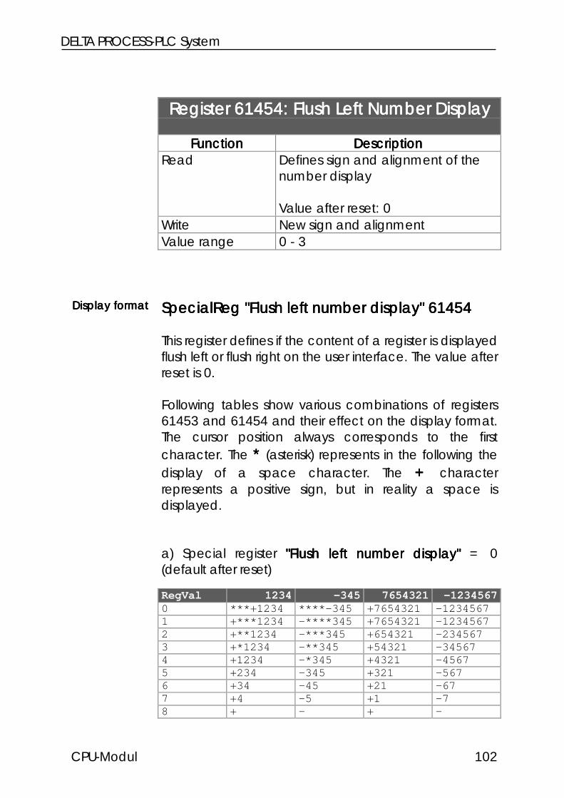
DELTA PROCESS-PLC System
CPU-Modul 102
Register 61454: Flush Left Number DisplayRegister 61454: Flush Left Number DisplayRegister 61454: Flush Left Number DisplayRegister 61454: Flush Left Number Display
FunctionFunctionFunctionFunction DescriptionDescriptionDescriptionDescriptionRead Defines sign and alignment of the
number display
Value after reset: 0Write New sign and alignmentValue range 0 - 3
SpecialReg "Flush left number display" 61454SpecialReg "Flush left number display" 61454SpecialReg "Flush left number display" 61454SpecialReg "Flush left number display" 61454
This register defines if the content of a register is displayedflush left or flush right on the user interface. The value afterreset is 0.
Following tables show various combinations of registers61453 and 61454 and their effect on the display format.The cursor position always corresponds to the firstcharacter. The **** (asterisk) represents in the following thedisplay of a space character. The ++++ characterrepresents a positive sign, but in reality a space isdisplayed.
a) Special register "Flush left number display""Flush left number display""Flush left number display""Flush left number display" = 0(default after reset)
RegVal 1234 -345 7654321 -12345670 ***+1234 ****-345 +7654321 -12345671 +***1234 -****345 +7654321 -12345672 +**1234 -***345 +654321 -2345673 +*1234 -**345 +54321 -345674 +1234 -*345 +4321 -45675 +234 -345 +321 -5676 +34 -45 +21 -677 +4 -5 +1 -78 + - + -
Display formatDisplay formatDisplay formatDisplay format

CPU Module
CPU Module103
b) Special register "Flush left number display""Flush left number display""Flush left number display""Flush left number display" = 1
RegVal 1234 -345 7654321 -12345670 +1234 -345 +7654321 -12345671 + - + -2 +1 -3 +7 -13 +12 -34 +76 -124 +123 -345 +765 -1235 +1234 -345* +7654 -12346 +1234* -345** +76543 -123457 +1234** -345*** +765432 -1234568 +1234*** -345**** +7654321 -1234567
c) Special register "Flush left number display""Flush left number display""Flush left number display""Flush left number display" = 2corresponds to point a) but no sign is displayed.
d) Special register "Flush left number display""Flush left number display""Flush left number display""Flush left number display" = 3corresponds to point b) and considers additionallyflag 2055.
Special flag 2055: leading blanks / zerosSpecial flag 2055: leading blanks / zerosSpecial flag 2055: leading blanks / zerosSpecial flag 2055: leading blanks / zeros
Flag 2055 MeaningFlag 2055=0(default leading blanks if flush right
and Reg 61453≠0Flag 2055=1 leading zeros if flush right
and Reg 61453≠0

DELTA PROCESS-PLC System
CPU-Modul 104
Register 61455: Field Width forRegister 61455: Field Width forRegister 61455: Field Width forRegister 61455: Field Width forUSER_INPUT
FunctionFunctionFunctionFunction DescriptionDescriptionDescriptionDescriptionRead Current field width for the
USER_INPUT instruction
Value after reset: 0Write New field widthValue range 1 - 8
Defines the number of places for value input via theuser interface. As a maximum 8 places can bereserved for an user input. If only 2 or 3 digit values areto be entered register 61455 allows to reserve only theactually needed places. This is necessary if a lot of textsand numbers have to be displayed on the userinterface.
ReservedReservedReservedReservednumber ofnumber ofnumber ofnumber ofplaces forplaces forplaces forplaces for
value inputvalue inputvalue inputvalue input
Note:Note:Note:Note:
The sign always occupies 1 place on the display.The sign always occupies 1 place on the display.The sign always occupies 1 place on the display.The sign always occupies 1 place on the display.Register 61453 has to contain 7 if a 6 digit value withRegister 61453 has to contain 7 if a 6 digit value withRegister 61453 has to contain 7 if a 6 digit value withRegister 61453 has to contain 7 if a 6 digit value withsign is to be displayed.sign is to be displayed.sign is to be displayed.sign is to be displayed.

CPU Module
CPU Module105
Register 61648: Indirect Cursor Position forRegister 61648: Indirect Cursor Position forRegister 61648: Indirect Cursor Position forRegister 61648: Indirect Cursor Position forDISPLAY_TEXT, , , , DISPLAY_REG
FunctionFunctionFunctionFunction DescriptionDescriptionDescriptionDescriptionRead Current value for the indirect cursor
position
Value after reset: 0Write New indirect cursor positionValue range 0 - 127
If the cursor position parameter of the DISPLAY_TEXT,DISPLAY_REG instructions is 0 the cursor positiondefined in register 61648 is used. If the content of thisregister is also 0, the display text/value is annexed to thelast output.
Register 61649: Indirect Cursor Position forRegister 61649: Indirect Cursor Position forRegister 61649: Indirect Cursor Position forRegister 61649: Indirect Cursor Position forUSER_INPUT
FunctionFunctionFunctionFunction DescriptionDescriptionDescriptionDescriptionRead Current indirect cursor position
Value after reset: 0Write New indirect cursor positionValue range 0 - 127
If the cursor position parameter of the USER_INPUTinstructions is 0 the cursor position defined in register61649 is used. If the content of this register is also 0, thedisplay value is annexed to the last output.

DELTA PROCESS-PLC System
CPU-Modul 106
Register 61472: Restrictions for MonitorRegister 61472: Restrictions for MonitorRegister 61472: Restrictions for MonitorRegister 61472: Restrictions for MonitorFunctionsFunctionsFunctionsFunctions
FunctionFunctionFunctionFunction DescriptionDescriptionDescriptionDescriptionRead Current restrictions
Value after reset: 255Write New restrictions, bitcodedValue range 0 - 255
This register defines the keyboard functions that areavailable for the macine operator.The register can be used to release keyboard functionsthat are locked for the service personal.
Register bitRegister bitRegister bitRegister bit61472614726147261472
FunctionFunctionFunctionFunction
Bit 0 = 1Bit 0 = 0
Display of regisers by ´R´ key´R´ key has no function
Bit 1 = 1Bit 1 = 0
Display of flags (2 times ´R´)No display of flags
Bit 2 = 1Bit 2 = 0
Display of outputs by ´I/O´No display of outputs
Bit 3 = 1Bit 3 = 0
Display of inputs (2 times I/O´)No display of inputs
Bit 4 = 1Bit 4 = 0
Value assignment to registers by ´=´No assignment to registers
Bit 5 = 1Bit 5 = 0
Flag state change by ´=´No change of flags
Bit 6 = 1Bit 6 = 0
Output state change by ´=´No output state change
Bit 7 = 1Bit 7 = 0
Input display by ´=´No input display
Locking ofLocking ofLocking ofLocking ofkeyboardkeyboardkeyboardkeyboard
ranges for theranges for theranges for theranges for themachinemachinemachinemachineoperatoroperatoroperatoroperator

CPU Module
CPU Module107
Register 61653: Display Time forRegister 61653: Display Time forRegister 61653: Display Time forRegister 61653: Display Time forMonitor FunctionsMonitor FunctionsMonitor FunctionsMonitor Functions
FunctionFunctionFunctionFunction DescriptionDescriptionDescriptionDescriptionRead Current switch over time from
monitor - standard display in s
Value after reset: 3 (s)Write New switch over timeValue range 0 - 65535
Using the monitor mode the user can access to inputs,outputs, flags and registers via the user interface.Register 61653 defines the time for switching from themonitor screen to the standard screen. The switch overtakes place after the monitor input is confirmed by(ENTER). A value of 3 in register 61653 delays theswitch over for 3 seconds.
Switch overSwitch overSwitch overSwitch overtime monitor -time monitor -time monitor -time monitor -
standardstandardstandardstandarddisplaydisplaydisplaydisplay

DELTA PROCESS-PLC System
CPU-Modul 108
Register 61448: Display LanguageRegister 61448: Display LanguageRegister 61448: Display LanguageRegister 61448: Display Language
FunctionFunctionFunctionFunction DescriptionDescriptionDescriptionDescriptionRead Current user interface dialogue
language:0000: German1111: English
Value after reset: 0Write New user interface dialogue
language:0000: German1111: English
Value range 0 - 1
The register defines the dialogue language of the userinterface. This dialogue language refers to the operatingsystem functions of the user interface not to the displaytexts of the user program, for example the monitorfunction as register, input, output and flag access.
Note:Note:Note:Note:
The register takes over the dialog language of SYMPASThe register takes over the dialog language of SYMPASThe register takes over the dialog language of SYMPASThe register takes over the dialog language of SYMPASduring program transfer.during program transfer.during program transfer.during program transfer.

CPU Module
CPU Module109
7.1.5 User Interface Flags7.1.5 User Interface Flags7.1.5 User Interface Flags7.1.5 User Interface Flags
Flag 2112: User Interface Operation afterFlag 2112: User Interface Operation afterFlag 2112: User Interface Operation afterFlag 2112: User Interface Operation aftereach User Taskeach User Taskeach User Taskeach User Task
FunctionFunctionFunctionFunction DescriptionDescriptionDescriptionDescriptionRead Current user interface priority:
0000: the user interface is served afterexecution of all user task
1111: the user interface is served aftereach user task
Value after reset: 0Write Set for high, clear for low priority of
the user interface
Definition of the user interface priority. The user interfaceis served in a background task. In most cases the userinterface priority is lower than the priority of the userprogram. Therefore the user interface is served afterexecution of all user tasks. Normally this is sufficient sincethe delay times are about 1/100s and the user does notconsider this as delay.The priority of the user interface can be increased bysetting of flag 2112 if a large amout of values aredisplayed especially on the 4 line user interfaces. Nowthe user interface is served after each user task (task1,UI, task2, UI, task3, UI, etc.).
User interfaceUser interfaceUser interfaceUser interfaceprioritypriorityprioritypriority

DELTA PROCESS-PLC System
CPU-Modul 110
Note:Note:Note:Note:
Normally the user interface is operated with low priority.Normally the user interface is operated with low priority.Normally the user interface is operated with low priority.Normally the user interface is operated with low priority.If considerable delays are recognised during user input,If considerable delays are recognised during user input,If considerable delays are recognised during user input,If considerable delays are recognised during user input,setting of flag 2112 increases the priority. In most casessetting of flag 2112 increases the priority. In most casessetting of flag 2112 increases the priority. In most casessetting of flag 2112 increases the priority. In most casescomplex display and input functions are needed duringcomplex display and input functions are needed duringcomplex display and input functions are needed duringcomplex display and input functions are needed duringadjustment and manual operation of the machine.adjustment and manual operation of the machine.adjustment and manual operation of the machine.adjustment and manual operation of the machine.Thus there is the possibility to set the flag (high priority)Thus there is the possibility to set the flag (high priority)Thus there is the possibility to set the flag (high priority)Thus there is the possibility to set the flag (high priority)during manual operation and clear the flag (low priority)during manual operation and clear the flag (low priority)during manual operation and clear the flag (low priority)during manual operation and clear the flag (low priority)for the automatic mode.for the automatic mode.for the automatic mode.for the automatic mode.

CPU Module
CPU Module111
User Interface ControlUser Interface ControlUser Interface ControlUser Interface ControlKeys and LEDKeys and LEDKeys and LEDKeys and LED
User Interface LED ControlUser Interface LED ControlUser Interface LED ControlUser Interface LED Control
LED, KeyLED, KeyLED, KeyLED, Key SpecialSpecialSpecialSpecialFlagFlagFlagFlag
LED, KeyLED, KeyLED, KeyLED, Key SpecialSpecialSpecialSpecialFlagFlagFlagFlag
LED F1 2224 LED F7 2230LED F2 2225 LED F8 2231LED F3 2226 LED F9 2232LED F4 2227 LED F10 2233LED F5 2228 LED F11 2234LED F6 2229 LED F12 2235
Query of User Interface KeysQuery of User Interface KeysQuery of User Interface KeysQuery of User Interface Keys
KeyKeyKeyKey SpecialSpecialSpecialSpecialFlagFlagFlagFlag
SHIFT +SHIFT +SHIFT +SHIFT +KeyKeyKeyKey
SpecialSpecialSpecialSpecialFlagFlagFlagFlag
Function KeysFunction KeysFunction KeysFunction Keys
F1 2201 SHIFT-F1 2181F2 2202 SHIFT-F2 2182F3 2203 SHIFT-F3 2183F4 2204 SHIFT-F4 2184F5 2205 SHIFT-F5 2185F6 2206 SHIFT-F6 2186F7 2207 SHIFT-F7 2187F8 2208 SHIFT-F8 2188F9 2209 SHIFT-F9 2189F10 2210 SHIFT-F10 2190F11 2211 SHIFT-F11 2191F12 2212 SHIFT-F12 2192

DELTA PROCESS-PLC System
CPU-Modul 112
Special Function KeysSpecial Function KeysSpecial Function KeysSpecial Function Keys
<- 2214 SHIFT <- 2193-> 2213 SHIFT -> 2194C 2218 SHIFT C 2198ENTER 2219 SHIFT ENTER 2199SHIFT 2200= 2217 SHIFT = 2197. 2222 SHIFT . 2223- 2220 SHIFT - 2221R 2215 SHIFT R 2195I/O 2216 SHIFT I/O 2196
Numerical KeysNumerical KeysNumerical KeysNumerical Keys
0 2160 SHIFT 0 21701 2161 SHIFT 1 21712 2162 SHIFT 2 21723 2163 SHIFT 3 21734 2164 SHIFT 4 21745 2165 SHIFT 5 21756 2166 SHIFT 6 21767 2167 SHIFT 7 21778 2168 SHIFT 8 21789 2169 SHIFT 9 2179
User Interface ControlUser Interface ControlUser Interface ControlUser Interface Control
2051 the USER_INPUT instruction isactive
2053 USER_INPUT terminated bytimeout
2112 User interface operated aftereach user task (high priority)
User Interface RestrictionsUser Interface RestrictionsUser Interface RestrictionsUser Interface Restrictions

CPU Module
CPU Module113
2052 Input by user interface locked2054 ENTER key does not switches
to monitor mode2096 No register display 0 = locked2097 No flag display 0 = locked2098 No output display 0 = locked2099 No input display 0 = locked2100 No change of registers 0 = locked2101 No change of flags 0 = locked2102 No change of outputs 0 = locked2103 No continuous display of
inputs

DELTA PROCESS-PLC System
CPU-Modul 114
7.2 Network Operation
7.2.1 JETWay-H: JETTER Data Highway7.2.1 JETWay-H: JETTER Data Highway7.2.1 JETWay-H: JETTER Data Highway7.2.1 JETWay-H: JETTER Data Highway
Several controllers of the PROCESS-PLC family can beaccessed from one host via data highway JETWay-H.This means:
• Process monitoring• Programming• Data transfer• Operation data aquisition• Maintenance, of each controller directly
Remote maintenance is possible if a modem is used.
The maximum number of network participants is 126.
Access to upAccess to upAccess to upAccess to upto 126 networkto 126 networkto 126 networkto 126 networkparticipants byparticipants byparticipants byparticipants by
one host viaone host viaone host viaone host viaJETWay-HJETWay-HJETWay-HJETWay-H
Note:Note:Note:Note:
For terminal description and parametering of theFor terminal description and parametering of theFor terminal description and parametering of theFor terminal description and parametering of theJETWay-H see ChapterJETWay-H see ChapterJETWay-H see ChapterJETWay-H see Chapter 6.3.2.2 PC Programming6.3.2.2 PC Programming6.3.2.2 PC Programming6.3.2.2 PC ProgrammingInterface (JETWay-H)Interface (JETWay-H)Interface (JETWay-H)Interface (JETWay-H)

CPU Module
CPU Module115
Figure 16: JETWay-H for the central controller

DELTA PROCESS-PLC System
CPU-Modul 116
7.2.2 JETWay-R: The Process Level7.2.2 JETWay-R: The Process Level7.2.2 JETWay-R: The Process Level7.2.2 JETWay-R: The Process Level
The JETWay-R network provides two functions:
1. The hierarchic connection of PROCESS-PLC in networks2. Connection of decentralized peripheral devices like
remote I/O and valve blocks
The maximum number of participants of each level is126. JETWay is a mono master network, that meansthere are 1 master and 125 slaves.

CPU Module
CPU Module117
Figure 8: JETWay-R for the process level

DELTA PROCESS-PLC System
CPU-Modul 118
7.2.3 Terminals7.2.3 Terminals7.2.3 Terminals7.2.3 Terminals
The JETWay-R is used to connect PROCESS-PLC and/orPROCESS-PLC and remote I/O, valve blocks, etc.
JETWay-R CableJETWay-R CableJETWay-R CableJETWay-R Cable
ConnectionConnectionConnectionConnectionon DELTAon DELTAon DELTAon DELTA
sidesidesideside
ShieldingShieldingShieldingShielding SpecificationSpecificationSpecificationSpecificationmax. Lengthmax. Lengthmax. Lengthmax. Length
9 pin Sub-D-male NET1NET1NET1NET1
or
9 pin Sub-D-male NET2NET2NET2NET2
Attach shield at bothAttach shield at bothAttach shield at bothAttach shield at bothsides !sides !sides !sides !
Use metallisedUse metallisedUse metallisedUse metallisedhousings !housings !housings !housings !
RS485
max.cable length:
400m
PinPinPinPin SignalSignalSignalSignal RemarkRemarkRemarkRemark
7777 Gnd8888 Data +9999 Data -

CPU Module
CPU Module119
Note:Note:Note:Note:
If you make the cable yourself, the following minimumIf you make the cable yourself, the following minimumIf you make the cable yourself, the following minimumIf you make the cable yourself, the following minimumrequirements must be considered:requirements must be considered:requirements must be considered:requirements must be considered:
Number of wires:Number of wires:Number of wires:Number of wires: 3333Diameter:Diameter:Diameter:Diameter: 0,25mm0,25mm0,25mm0,25mm2222
Connection:Connection:Connection:Connection: Sub-D, metallisedSub-D, metallisedSub-D, metallisedSub-D, metallisedShielding:Shielding:Shielding:Shielding: total, not pairedtotal, not pairedtotal, not pairedtotal, not paired
The shield must on both sides have extensive contactThe shield must on both sides have extensive contactThe shield must on both sides have extensive contactThe shield must on both sides have extensive contactto the connector shells.to the connector shells.to the connector shells.to the connector shells.
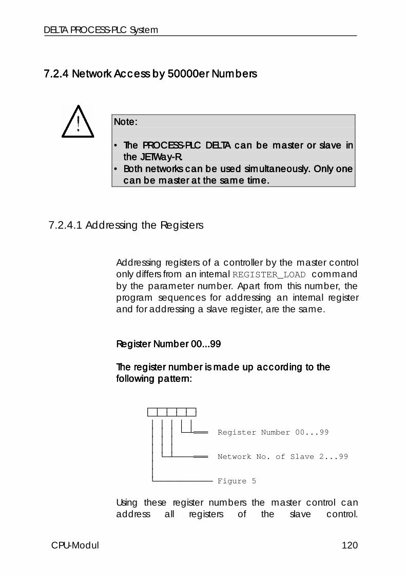
DELTA PROCESS-PLC System
CPU-Modul 120
7.2.4 Network Access by 50000er Numbers7.2.4 Network Access by 50000er Numbers7.2.4 Network Access by 50000er Numbers7.2.4 Network Access by 50000er Numbers
7.2.4.1 Addressing the Registers
Addressing registers of a controller by the master controlonly differs from an internal REGISTER_LOAD commandby the parameter number. Apart from this number, theprogram sequences for addressing an internal registerand for addressing a slave register, are the same.
Register Number 00...99Register Number 00...99Register Number 00...99Register Number 00...99
The register number is made up according to theThe register number is made up according to theThe register number is made up according to theThe register number is made up according to thefollowing pattern:following pattern:following pattern:following pattern:
Register Number 00...99 Network No. of Slave 2...99 Figure 5
Using these register numbers the master control canaddress all registers of the slave control.
Note:Note:Note:Note:
• The PROCESS-PLC DELTA can be master or slave inThe PROCESS-PLC DELTA can be master or slave inThe PROCESS-PLC DELTA can be master or slave inThe PROCESS-PLC DELTA can be master or slave inthe JETWay-R.the JETWay-R.the JETWay-R.the JETWay-R.
• Both networks can be used simultaneously. Only oneBoth networks can be used simultaneously. Only oneBoth networks can be used simultaneously. Only oneBoth networks can be used simultaneously. Only onecan be master at the same time.can be master at the same time.can be master at the same time.can be master at the same time.

CPU Module
CPU Module121
Example:Example:Example:Example:
Register 62 of the slave control with network number 32 isaddressed from a PROCESS-PLC by the instruction
REGISTER_LOAD [ 100 with R(53262) ]
If a register which number is greater than 99 is to beaddressed, a numeric offset value is to be written intoregister 61831 of the slave control. This value will beadded to the register number in the program of themaster control, when registers of the slave control areaddressed by the master control.
Register 61831:Register 61831:Register 61831:Register 61831:
Number offset for register; the register is on the slavecontrol.
This value is added to the register number in the mastercontrol program. The value of the total results is theregister number in the slave control, which is accessedby the master control.
The command
REGISTER_LOAD [ 100 with R(53262) ]
in the master controller program, plus value 100 writteninto register 61831 of the slave controller of networknumber 32 serves for actually addressing register 162 ofthe slave controller.
The input offsetThe input offsetThe input offsetThe input offsetregister is inregister is inregister is inregister is in
the slavethe slavethe slavethe slavecontrolcontrolcontrolcontrol
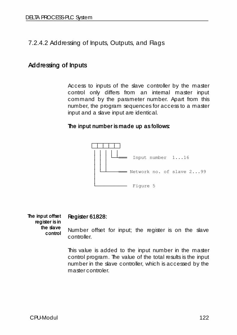
DELTA PROCESS-PLC System
CPU-Modul 122
7.2.4.2 Addressing of Inputs, Outputs, and Flags
Addressing of InputsAddressing of InputsAddressing of InputsAddressing of Inputs
Access to inputs of the slave controller by the mastercontrol only differs from an internal master inputcommand by the parameter number. Apart from thisnumber, the program sequences for access to a masterinput and a slave input are identical.
The input number is made up as follows:The input number is made up as follows:The input number is made up as follows:The input number is made up as follows:
Input number 1...16 Network no. of slave 2...99 Figure 5
Register 61828:Register 61828:Register 61828:Register 61828:
Number offset for input; the register is on the slavecontroller.
This value is added to the input number in the mastercontrol program. The value of the total results is the inputnumber in the slave controller, which is accessed by themaster controler.
The input offsetThe input offsetThe input offsetThe input offsetregister is inregister is inregister is inregister is in
the slavethe slavethe slavethe slavecontrolcontrolcontrolcontrol

CPU Module
CPU Module123
Value after Reset: 100
Example:Example:Example:Example:
Input 112 in the slave control with network number 4 isaddressed by the master control by
INPUT 50412
Note:Note:Note:Note:
The numbering of the inputs in the different slots has toThe numbering of the inputs in the different slots has toThe numbering of the inputs in the different slots has toThe numbering of the inputs in the different slots has tobe considered for definition of the register numberbe considered for definition of the register numberbe considered for definition of the register numberbe considered for definition of the register numberoffset content.offset content.offset content.offset content.
Reg 61828 = slot number x 100Reg 61828 = slot number x 100Reg 61828 = slot number x 100Reg 61828 = slot number x 100

DELTA PROCESS-PLC System
CPU-Modul 124
Addressing the OutputsAddressing the OutputsAddressing the OutputsAddressing the Outputs
Access to outputs of the slave control by the mastercontrol only differs from an internal master outputcommand by the parameter number. Apart from thisnumber, the program sequences for access to a masteroutput and a slave output are identical.
The output number is made up as follows:The output number is made up as follows:The output number is made up as follows:The output number is made up as follows:
Output number 1...16 Network no. of slave 2...99 Figure 5
Register 61829:Register 61829:Register 61829:Register 61829:
Number offset for output; the register is on the slavecontrol.
This value is added to the output number in the mastercontroller program. The value of the total results is theoutput number in the slave controller, which is accessedby the master controller.
The outputThe outputThe outputThe outputoffset registeroffset registeroffset registeroffset registeris in the slaveis in the slaveis in the slaveis in the slave
controlcontrolcontrolcontrol

CPU Module
CPU Module125
Value after Reset: 100
Example:Example:Example:Example:
Output 113 in the slave control with network number 4 isaddressed by the master control by
OUTPUT 50413.
Note:Note:Note:Note:
The numbering of the outputs in the different slots hasThe numbering of the outputs in the different slots hasThe numbering of the outputs in the different slots hasThe numbering of the outputs in the different slots hasto be considered for definition of the register numberto be considered for definition of the register numberto be considered for definition of the register numberto be considered for definition of the register numberoffset content.offset content.offset content.offset content.
Reg 61829 = slot number x 100Reg 61829 = slot number x 100Reg 61829 = slot number x 100Reg 61829 = slot number x 100

DELTA PROCESS-PLC System
CPU-Modul 126
Addressing the FlagsAddressing the FlagsAddressing the FlagsAddressing the Flags
Access to flags of the slave control by the master controlonly differs from an internal master flag command by theparameter number. Apart from this number, the programsequences for access to a master flag and a slave flagare identical.
The flag number is made up as follows:The flag number is made up as follows:The flag number is made up as follows:The flag number is made up as follows:
Flag number 0...99 Network no. of slave 2...99 Figure 5
Register 61830:Register 61830:Register 61830:Register 61830:
Number offset for the flag; the register is on the slavecontroller.
This value is added to the flag number in the mastercontroller program. The value of the total results in theflag number in the slave controller, which is accessed bythe master controller.
The flag offsetThe flag offsetThe flag offsetThe flag offsetregister is inregister is inregister is inregister is in
the slavethe slavethe slavethe slavecontrolcontrolcontrolcontrol

CPU Module
CPU Module127
Value after Reset: 0
Example:Example:Example:Example:
Flag 154 in the slave control with network number 12 isaddressed by the master control by
FLAG 51254.
Before that, value 100 must be written into the numberoffset register flags (on the slave control).

DELTA PROCESS-PLC System
CPU-Modul 128
7.2.57.2.57.2.57.2.5 Network Access by Network Access by Network Access by Network Access by N-SEND REGISTER and and and andN-GET REGISTER
Note:Note:Note:Note:
These register numbers are not influenced by theThese register numbers are not influenced by theThese register numbers are not influenced by theThese register numbers are not influenced by thenumber offset in register 61831.number offset in register 61831.number offset in register 61831.number offset in register 61831.
Note:Note:Note:Note:
The PROCESS-PLC DELTA can be operated as masterThe PROCESS-PLC DELTA can be operated as masterThe PROCESS-PLC DELTA can be operated as masterThe PROCESS-PLC DELTA can be operated as masteror slave in JETWay-R .or slave in JETWay-R .or slave in JETWay-R .or slave in JETWay-R .

CPU Module
CPU Module129
The N-SEND-REGISTER InstructionThe N-SEND-REGISTER InstructionThe N-SEND-REGISTER InstructionThe N-SEND-REGISTER Instruction
By the following instruction, registers can be written intoslave controllers by the master controller:
N-SEND REGISTER [to <PASE no.>from reg<source reg>into reg<destination reg>]
PASE no.PASE no.PASE no.PASE no.
PASE no. stands for the network number of the slavecontroller which is to be addressed via the network.
Source regSource regSource regSource reg
Here, the number of the register is assigned. This is theregister the value of which is to be transmitted to a slaveby the network.
Destination regDestination regDestination regDestination reg
Here, the number of the register is assigned which thecontents from the master controller is transferred into. Thisregister is on the slave controller of the slave numberPASE- no.

DELTA PROCESS-PLC System
CPU-Modul 130
Example:Example:Example:Example:
N-SEND REGISTER [To 2 from reg100 into reg200]
Result: The value of master controller register 100 will,after this instruction, be written in slave controller register200 of network number 2222
The N-GET Register InstructionThe N-GET Register InstructionThe N-GET Register InstructionThe N-GET Register Instruction
By the following instruction slave controller registers canbe read by the master controller:
N-GET REGISTER [From <PASE no.> reg<source reg>,into reg here <reg>]
PASE NO.PASE NO.PASE NO.PASE NO.
PASE NO. is the network number of the slave controllerwhich is to be addressed via network.
Source RegSource RegSource RegSource Reg
The source reg is the number of the register in the slavecontroller, which is to be written into the master controller.
Destination RegDestination RegDestination RegDestination Reg
The destination register is the number of the mastercontrol register into which the value of the slave register isto be written.

CPU Module
CPU Module131
Example:Example:Example:Example:
N-GET REGISTER [from 2 Reg200, Reg. here=100]
Result: Value of slave controller register 200 (networknumber 2) is copied into master controller register 100 bythis command.

DELTA PROCESS-PLC System
CPU-Modul 132
7.2.6 Network Registers7.2.6 Network Registers7.2.6 Network Registers7.2.6 Network Registers
Overview Network RegistersOverview Network RegistersOverview Network RegistersOverview Network Registers
Network 1 ControlNetwork 1 ControlNetwork 1 ControlNetwork 1 Control
61585 Network reaction time in ms 1) 0 .. 2552) 03)
61586 Network instrcution executiontime in ms
1) 0 .. 2552) 03)
61588 Timeout time network 1 1) 0 .. 2552)3)
61589 Indirect network addressing 1) 0 .. 2552) 03)
61828 50000er offset for inputs 1) 0 .. 655352) 1003)
61829 50000er offset for outputs 1) 0 .. 655352) 2003)
61830 50000er offset for flags 1) 0 .. 655352) 03)
61831 50000er offset for registers 1) 0 .. 655352) 03)
61955 Number checksum errorsnetwork receiving
1) -8388608 .. +83886072) 03)
62995 Network 1 number 1) -8388608 .. +83886072) Register 632413)
62996 Baudrate Network 10 1501 3002 6003 12004 24005 48006 96007 192008 38400
1) 0 .. 2552) Register 632423)

CPU Module
CPU Module133
9 5760010 7680011..14 115200 11=default
63242 Baud rate Network EEPROM63241 Network number network 1 at
switch-on (EEPROM)1) 0 .. 2552) last number3)
Network 2 Control / Free Prog. InterfaceNetwork 2 Control / Free Prog. InterfaceNetwork 2 Control / Free Prog. InterfaceNetwork 2 Control / Free Prog. Interface
61499 Receiving buffer level 1) 0 .. 1282) 03)
61502 Tansmission buffer level 1) 0 .. 1282) 03)
61508 Interface stateBit0=1 one or more
charecters lost duringreceiving
Bit1=1 stop bit errorBit2=1 parity errorBit3=1 bit0 to 2 is or was not 0Bit4=1 receiving buffer
overflowBit5=1 transmission buffer
overflow61511 Timeout time network 2 1) 0 .. 255
2)3)
62989 ConfigurationBit0 0=PRIM, 1=net2Bit1 reservedBit2 0=1, 1=2 stop bitBit3 0=7, 1=8 bit/charBit4,5 00=no parity
01=not allowed10=odd11=even
Bit7,6 00=RS23201=RS485 (4 wire)10=RS42211=RS485 (2 wire)
Default: PRIM, RS232,8N1,9600
1) 0 .. 2552)3)
62990 Baud rate0 1501 3002 6003 12004 24005 48006 9600 default7 192008 38400
1) 0 .. 2552) 63)

DELTA PROCESS-PLC System
CPU-Modul 134
9 5760010 7680011..14 115200
62991 Network number network 2 1) 0 .. 2552) 23)
62992 Transmission buffer 1) 0 .. 2552) 03)
62993 Receiving buffer withcharacter removing
1) 0 .. 2552) 03)
62994 Receiving buffer withoutcharacter removing
1) 0 .. 2552) 03)
Each PROCESS-PLC system provides at least 1 interfacefor the JETWay network from JETTER. The registersmenitioned here specifiy the network number and thetransfer parameters.
Register 61585: Network Reaction TimeRegister 61585: Network Reaction TimeRegister 61585: Network Reaction TimeRegister 61585: Network Reaction Time
FunctionFunctionFunctionFunction DescriptionDescriptionDescriptionDescriptionRead Reaction time in ms
Value after reset: last timeWrite prohibitedValue range 0 .. 255
The time starts with the start of the network instructionand stops after response of the slave controller.
Register 61586: Network InstructionRegister 61586: Network InstructionRegister 61586: Network InstructionRegister 61586: Network Instruction

CPU Module
CPU Module135
Execution TimeExecution TimeExecution TimeExecution Time
FunctionFunctionFunctionFunction DescriptionDescriptionDescriptionDescriptionRead execution time in ms
Value after reset: last timeWrite prohibitedValue range 0 .. 255
Contains the execution time of the last executednetwork instruction. This execution time consists of thenetwork reaction time plus the time that is necessary toexecute the response of the slave controller.
Register61588: Timeout Time Network 1Register61588: Timeout Time Network 1Register61588: Timeout Time Network 1Register61588: Timeout Time Network 1
FunctionFunctionFunctionFunction DescriptionDescriptionDescriptionDescriptionRead Timeout time in ms
Value after reset: 250Write Set new TimeoutValue range 0 .. 255
Register 61589: Indirect Network AddressingRegister 61589: Indirect Network AddressingRegister 61589: Indirect Network AddressingRegister 61589: Indirect Network Addressing
FunctionFunctionFunctionFunction DescriptionDescriptionDescriptionDescriptionRead Current indirect network number
Value after reset: 0Write New indirect network numberValue range 0 .. 255

DELTA PROCESS-PLC System
CPU-Modul 136
Register 61828: Input OffsetRegister 61828: Input OffsetRegister 61828: Input OffsetRegister 61828: Input Offset
FunctionFunctionFunctionFunction DescriptionDescriptionDescriptionDescriptionRead Current input offset
Value after reset 100Write New inpu offsetValue range 0 - 65535
This value is added to the input number of a networkaccess by 50000er numbers. See Chapter 7.2.4.2 .
Register 61829: Output OffsetRegister 61829: Output OffsetRegister 61829: Output OffsetRegister 61829: Output Offset
FunctionFunctionFunctionFunction DescriptionDescriptionDescriptionDescriptionRead Current output offset
Value after eset: 200Write New output offsetValue range 0 - 65535
This value is added to the output number of a networkaccess by 50000er numbers. See Chapter 7.2.4.2 .
Register 61830: Flag OffsetRegister 61830: Flag OffsetRegister 61830: Flag OffsetRegister 61830: Flag Offset
FunctionFunctionFunctionFunction DescriptionDescriptionDescriptionDescriptionRead Current flag offset
Value after reset 0Write New flag offset
Input offsetInput offsetInput offsetInput offset
Output offsetOutput offsetOutput offsetOutput offset
Flag offsetFlag offsetFlag offsetFlag offset

CPU Module
CPU Module137
Value range 0 - 65535
This value is added to the flag number of a networkaccess by 50000er numbers. See Chapter 7.2.4.2 .
Register 61831: Register OffsetRegister 61831: Register OffsetRegister 61831: Register OffsetRegister 61831: Register Offset
FunctionFunctionFunctionFunction DescriptionDescriptionDescriptionDescriptionRead Current register offset
Value after reset: 0Write New register offsetValue range 0 .. 65535
This value is added to the input number of a networkaccess by 50000er numbers. See Chapter 7.2.4.1 .
Register 62995: Network NumberRegister 62995: Network NumberRegister 62995: Network NumberRegister 62995: Network NumberNetwork 1Network 1Network 1Network 1
FunctionFunctionFunctionFunction DescriptionDescriptionDescriptionDescriptionRead Current number of the JETWay
paticipantValue after reset: see Reg 63241
Write New JETWay network number:0000: not active1111: master2 - 1272 - 1272 - 1272 - 127: possible slave numbers
Value range 0 .. 127
Register offsetRegister offsetRegister offsetRegister offset

DELTA PROCESS-PLC System
CPU-Modul 138
Register 62996: Baud RateRegister 62996: Baud RateRegister 62996: Baud RateRegister 62996: Baud RateNetwork 1Network 1Network 1Network 1
FunctionFunctionFunctionFunction DescriptionDescriptionDescriptionDescriptionRead Current value for the JETWay-R baud
rateValue after reset: Reg 63242
Write New JETWay-R baud rate0000 = 150, 2222 = 300, 3333 = 600, 4444 =1200, 5555 = 2400, 6666 = 4800, 7777 =19200, 8888 = 38400, 9999 = 57600, 10101010 =76800, 11111111 = 115200
Value range 1.. 255
Register 63241: Network NumberRegister 63241: Network NumberRegister 63241: Network NumberRegister 63241: Network NumberNetwork 1 at Power-On (EEPROM)Network 1 at Power-On (EEPROM)Network 1 at Power-On (EEPROM)Network 1 at Power-On (EEPROM)
FunctionFunctionFunctionFunction DescriptionDescriptionDescriptionDescriptionRead Network number at power-on
Value after reset: last numberWrite New network number at power-onValue range 0 .. 255
See register 62995 network number network 1. Register62995 is initialized with the content of register 63141during power-up if register 62995 contains a number inthe range of 2 .. 126 (only slave number are valid). Ifregister 63241 contains an invalid network numberregister 62995 is initialized with 2 (slave 2).

CPU Module
CPU Module139
Register 63242: Baud RateRegister 63242: Baud RateRegister 63242: Baud RateRegister 63242: Baud RateNetwork 1 at Power-On (EEPROM)Network 1 at Power-On (EEPROM)Network 1 at Power-On (EEPROM)Network 1 at Power-On (EEPROM)
FunctionFunctionFunctionFunction DescriptionDescriptionDescriptionDescriptionRead Baud rate at power-on
Value after reset: last numberWrite New baud rate at power-onValue range 0 .. 255
See register 62996 baud rate network 1.
Register61511: Timeout Time Network 2Register61511: Timeout Time Network 2Register61511: Timeout Time Network 2Register61511: Timeout Time Network 2
FunctionFunctionFunctionFunction DescriptionDescriptionDescriptionDescriptionRead Timeout time in ms
Value after reset: 250Write Set timeout timeValue range 0 .. 255
Register 62990: Baud RateRegister 62990: Baud RateRegister 62990: Baud RateRegister 62990: Baud RateNetwork 2Network 2Network 2Network 2
FunctionFunctionFunctionFunction DescriptionDescriptionDescriptionDescriptionRead Current baud rate JETWay-R
Value after reset: 6 (9600)Write new baud rate JETWay-R
0000 = 150, 2222 = 300, 3333 = 600, 4444 =1200, 5555 = 2400, 6666 = 4800, 7777 =

DELTA PROCESS-PLC System
CPU-Modul 140
19200, 8888 = 38400, 9999 = 57600, 10101010 =76800, 11111111 = 115200
Value range 1 .. 255
Register 62991: Network NumberRegister 62991: Network NumberRegister 62991: Network NumberRegister 62991: Network NumberNetwork 2Network 2Network 2Network 2
FunctionFunctionFunctionFunction DescriptionDescriptionDescriptionDescriptionRead Current number of JETWay
participantValue after reset: 2
Write New network number:0000: not active1111: master2 - 1272 - 1272 - 1272 - 127: possible slave numbers
Value range 0 .. 255
Register 62989: ConfigurationRegister 62989: ConfigurationRegister 62989: ConfigurationRegister 62989: ConfigurationNET2 - Free Programmable InterfaceNET2 - Free Programmable InterfaceNET2 - Free Programmable InterfaceNET2 - Free Programmable Interface
FunctionFunctionFunctionFunction DescriptionDescriptionDescriptionDescriptionRead Current configuration
Value after reset: 8Write New configuration:
Bit0Bit0Bit0Bit0 0=free prog, 1=Net 2Bit1Bit1Bit1Bit1 reservedBit2Bit2Bit2Bit2 0=1, 1=2 stop bitBit3Bit3Bit3Bit3 0=7, 1=8 bit / charBit4,5Bit4,5Bit4,5Bit4,5 00=no parity
01=prohibited10=odd

CPU Module
CPU Module141
11=evenBit7,6Bit7,6Bit7,6Bit7,6 00=RS232
01=RS485 (4 wire)10=RS42211=RS485 (2 wire)
Default:Default:Default:Default: PRIM, RS232, 8N1,9600PRIM, RS232, 8N1,9600PRIM, RS232, 8N1,9600PRIM, RS232, 8N1,9600Value range 0 .. 255
Note:Note:Note:Note:
If bit 0 = 1 (NET2 selected) all configurations are ignoredIf bit 0 = 1 (NET2 selected) all configurations are ignoredIf bit 0 = 1 (NET2 selected) all configurations are ignoredIf bit 0 = 1 (NET2 selected) all configurations are ignoredand not applied to the JETWay.and not applied to the JETWay.and not applied to the JETWay.and not applied to the JETWay.
DELTA PROCESS-PLC System
CPU-Modul 142
7.3 Free Programmable Interfaces
7.3.1 17.3.1 17.3.1 17.3.1 1stststst Free Programmable Interface via NET2 Connector Free Programmable Interface via NET2 Connector Free Programmable Interface via NET2 Connector Free Programmable Interface via NET2 Connector
7.3.1.1 Terminals, Configuration
Note:Note:Note:Note:
Either the JETWay via the NET2 connector or the FreeEither the JETWay via the NET2 connector or the FreeEither the JETWay via the NET2 connector or the FreeEither the JETWay via the NET2 connector or the FreeProgrammable Interface can be used. SimutaneouslyProgrammable Interface can be used. SimutaneouslyProgrammable Interface can be used. SimutaneouslyProgrammable Interface can be used. Simutaneouslyuse of both interfaces is not possible.use of both interfaces is not possible.use of both interfaces is not possible.use of both interfaces is not possible.

CPU Module
CPU Module143
RS232 CableRS232 CableRS232 CableRS232 CableFree Programmable Interface via NET2Free Programmable Interface via NET2Free Programmable Interface via NET2Free Programmable Interface via NET2
ConnectorConnectorConnectorConnector
PROCESS-PLCPROCESS-PLCPROCESS-PLCPROCESS-PLC SpecificationSpecificationSpecificationSpecificationmax. Lengthmax. Lengthmax. Lengthmax. Length
9 pin Sub-D-male
Attach shield at bothAttach shield at bothAttach shield at bothAttach shield at bothsides !sides !sides !sides !
Use metallisedUse metallisedUse metallisedUse metallisedhousings !housings !housings !housings !
RS232
max. cablelength: 15m
PinPinPinPin SignalSignalSignalSignal PinPinPinPin
2 TxD RxD3 RxD TxD7 Gnd
Via NET2Via NET2Via NET2Via NET2connectorconnectorconnectorconnector

DELTA PROCESS-PLC System
CPU-Modul 144
RS485 Cable (2 wire)RS485 Cable (2 wire)RS485 Cable (2 wire)RS485 Cable (2 wire)Free Programmable Interface at the NET2Free Programmable Interface at the NET2Free Programmable Interface at the NET2Free Programmable Interface at the NET2
ConnectorConnectorConnectorConnector
PROCESS-PLCPROCESS-PLCPROCESS-PLCPROCESS-PLC ShieldingShieldingShieldingShielding SpecificationSpecificationSpecificationSpecificationmax. Lengthmax. Lengthmax. Lengthmax. Length
9 pin Sub-D-male
Attach shield at bothAttach shield at bothAttach shield at bothAttach shield at bothsides !sides !sides !sides !
Use metallisedUse metallisedUse metallisedUse metallisedhousings !housings !housings !housings !
RS485
max.cable length:
400m
PinPinPinPin SignalSignalSignalSignal RemarkRemarkRemarkRemark
7 Gnd8 Data +9 Data -
Via NET2Via NET2Via NET2Via NET2connectorconnectorconnectorconnector
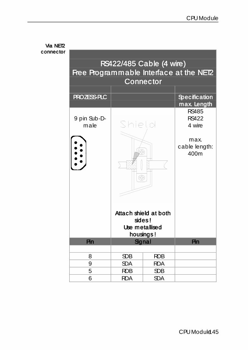
CPU Module
CPU Module145
RS422/485 Cable (4 wire)RS422/485 Cable (4 wire)RS422/485 Cable (4 wire)RS422/485 Cable (4 wire)Free Programmable Interface at the NET2Free Programmable Interface at the NET2Free Programmable Interface at the NET2Free Programmable Interface at the NET2
ConnectorConnectorConnectorConnector
PROZESS-PLCPROZESS-PLCPROZESS-PLCPROZESS-PLC SpecificationSpecificationSpecificationSpecificationmax. Lengthmax. Lengthmax. Lengthmax. Length
9 pin Sub-D-male
Attach shield at bothAttach shield at bothAttach shield at bothAttach shield at bothsides !sides !sides !sides !
Use metallisedUse metallisedUse metallisedUse metallisedhousings !housings !housings !housings !
RS485RS4224 wire
max.cable length:
400m
PinPinPinPin SignalSignalSignalSignal PinPinPinPin
8 SDB RDB9 SDA RDA5 RDB SDB6 RDA SDA
Via NET2Via NET2Via NET2Via NET2connectorconnectorconnectorconnector

DELTA PROCESS-PLC System
CPU-Modul 146
Register 62989: ConfigurationRegister 62989: ConfigurationRegister 62989: ConfigurationRegister 62989: ConfigurationNET2: Free Programmable InterfaceNET2: Free Programmable InterfaceNET2: Free Programmable InterfaceNET2: Free Programmable Interface
FunctionFunctionFunctionFunction DescriptionDescriptionDescriptionDescriptionRead Current configuration
Value after reset: 8Write New configuration:
Bit0 0=free prog, 1=Net 2Bit1 reservedBit2 0=1, 1=2 stop bitBit3 0=7, 1=8 bit / charBit4,5 00=no parity
01=prohibited10=odd11=even
Bit7,6 00=RS23201=RS485 (4 wire)10=RS42211=RS485 (2 wire)
Default:Default:Default:Default: PRIM, RS232, 8N1,9600PRIM, RS232, 8N1,9600PRIM, RS232, 8N1,9600PRIM, RS232, 8N1,9600Value range 0 .. 255
Remark:Remark:Remark:Remark:
Default setting: PRIM, RS232, 8N1, 9600Default setting: PRIM, RS232, 8N1, 9600Default setting: PRIM, RS232, 8N1, 9600Default setting: PRIM, RS232, 8N1, 9600
Remark:Remark:Remark:Remark:
PRIM = free programmable interface
Set parametersSet parametersSet parametersSet parameters

CPU Module
CPU Module147
7.3.1.2 Programming
Following programming example shows the handling ofthe free programmable interface.
Program listingProgram listingProgram listingProgram listing
0: ; ***************************************1: ; * The program receives the ASCII *2: ; * characters 'A' to 'Z' converts *3: ; * them into small characters and *4: ; * sends them back *5: ; * *6: ; ***************************************7: DEF_FUNCTION [ReceiPRIM, RP]
Par: rLimitTop, rLimitBottomVar: rHelp
8: ; ++++++++++++++++++++++++++++++++++++++9: ; + Function reads a character from +10: ; + the reception buffer +11: ; ++++++++++++++++++++++++++++++++++++++12: REGISTER_LOAD [rHelp with R(rPRIMRecei)] ;reads char from
;buffer13: ; Check character for valid range14: IF15: LIMITS [Reg=rHelp, low=R(rLimitBottom),
up=R(rLimitTop)]16: THEN17: REGISTER_LOAD [rChar with R(rHelp)] ;Char valid.18: ELSE19: REGZERO rChar ;Char not valid.20: THEN21: RETURN22: END_DEF23: DEF_FUNCTION [SendPRIM, SP]
Par: rSendChar24: ; ++++++++++++++++++++++++++++++++++++++25: ; + The function write a character +26: ; + into the transmission buffer +27: ; ++++++++++++++++++++++++++++++++++++++28: IF29: REG rSendFill ;At least 1 char30: < ;in buffer free ?31: 12832: THEN33: REG rPRIMSend ;send modified34: = ;received char35: REG rSendChar36: +37: 3238: THEN39: RETURN40: END_DEF41: TASK tPRIMHandling ----------------------------------42: REG rPRIMConfig ;Configuration43: = ;RS422,
even Parity44: b000000000000000010111000 ;8 bit, 1 stop bit.45: REGISTER_LOAD [rPRIMBaud with 7] ;19200 baud.46: LABEL sPRIMLoop47: IF48: NOT ;1 or more chars49: REGZERO rReceiFill ;recepted ?

DELTA PROCESS-PLC System
CPU-Modul 148
50: THEN51: ReceiPRIM [rLimitTop=90, rLimitBottom=65]52: IF53: REGZERO rChar ;valid char54: THEN ;available ?55: GOTO sPRIMLoop ;NO.56: ELSE57: SendPRIM [rSendChar=R(rChar)]58: REGZERO rZeichen ;Confirmation.59: sPRIMLoopEnd of program
Symbol listingSymbol listingSymbol listingSymbol listing
********** Task **********tPRIMhandling 0
********** Labels *********
MPRIMLoop !
********** Register **************
rPRIMConfig 62989rPRIMBaud 62990rPRIMSend 62992 ;Transmission registerrPRIMEmpf 62993 ;Reception registerrReceiFill 61499 ;Reception buffer filling levelrSendFill 61502 ;Transmission buffer filling levelrChar 100
In the example above the actual transmissionrespectively reception is realized by functions.
A character is transmittedA character is transmittedA character is transmittedA character is transmitted if the value is written into theregister.
A character is receivedA character is receivedA character is receivedA character is received if the value is read from thereception register. (Read access to register 62993removes the character)
The reception buffer filling levelThe reception buffer filling levelThe reception buffer filling levelThe reception buffer filling level is queried in register61499.
The transmission buffer level The transmission buffer level The transmission buffer level The transmission buffer level is queried in register61502.
TransmitTransmitTransmitTransmitcharactercharactercharactercharacter
ReceiveReceiveReceiveReceivecharactercharactercharactercharacter

CPU Module
CPU Module149
7.3.1.3 Free Programmable Interface Registers (NET2)
Register 61499: Reception Buffer FillingRegister 61499: Reception Buffer FillingRegister 61499: Reception Buffer FillingRegister 61499: Reception Buffer FillingLevelLevelLevelLevel
FunctionFunctionFunctionFunction DescriptionDescriptionDescriptionDescriptionRead Current filling level of the reception
bufferValue after reset: 0
Write prohibitedValue range 0 .. 128
Register 61502: Transmission Buffer FillingRegister 61502: Transmission Buffer FillingRegister 61502: Transmission Buffer FillingRegister 61502: Transmission Buffer FillingLevelLevelLevelLevel
FunctionFunctionFunctionFunction DescriptionDescriptionDescriptionDescriptionRead Current filling level of the
transmission bufferValue after reset: 0
Write prohibitedValue range 0 .. 128

DELTA PROCESS-PLC System
CPU-Modul 150
Register 61508: Interface StateRegister 61508: Interface StateRegister 61508: Interface StateRegister 61508: Interface State
FunctionFunctionFunctionFunction DescriptionDescriptionDescriptionDescriptionRead Current state
Value after reset: state
Interface stateBit0=1 one or more characters
lost during receptionBit1=1 stop bit errorBit2=1 parity errorBit3=1 bit 0 to 2 is or was not 0Bit4=1 reception buffer
overflowBit5=1 transmission buffer
overflowWrite prohibitedValue arnge 0 .. 128
Register 62989: ConfigurationRegister 62989: ConfigurationRegister 62989: ConfigurationRegister 62989: ConfigurationNET2: Free Programmable InterfaceNET2: Free Programmable InterfaceNET2: Free Programmable InterfaceNET2: Free Programmable Interface
FunctionFunctionFunctionFunction DescriptionDescriptionDescriptionDescriptionRead Current configuration
Value after reset: 8Write New configuration:
Bit0=1 0=free prog, 1=Net 2Bit1=1 reservedBit2=1 0=1, 1=2 stop bitBit3=1 0=7, 1=8 bit / charBit4,5 00=no parity
01=prohibited10=odd

CPU Module
CPU Module151
11=evenBit7,6 00=RS232
01=RS485 (4 wire)10=RS42211=RS485 (2 wire)
Default:Default:Default:Default: PRIM, RS232, 8N1,9600PRIM, RS232, 8N1,9600PRIM, RS232, 8N1,9600PRIM, RS232, 8N1,9600Value range 0 .. 255
Note:Note:Note:Note:
If bit 0 = 1 (Reg 62989) all other bits are vain.If bit 0 = 1 (Reg 62989) all other bits are vain.If bit 0 = 1 (Reg 62989) all other bits are vain.If bit 0 = 1 (Reg 62989) all other bits are vain.

DELTA PROCESS-PLC System
CPU-Modul 152
Register 62990: Baud RateRegister 62990: Baud RateRegister 62990: Baud RateRegister 62990: Baud Rate
FunctionFunctionFunctionFunction DescriptionDescriptionDescriptionDescriptionRead Current baud rate
Value after reset: 6Write New baud rate
0 1501 3002 6003 12004 24005 48006 9600 default7 192008 384009 5760010 7680011..14 115200
Value range 0 .. 255

CPU Module
CPU Module153
Register 62992: Transmission BufferRegister 62992: Transmission BufferRegister 62992: Transmission BufferRegister 62992: Transmission Buffer
FunctionFunctionFunctionFunction DescriptionDescriptionDescriptionDescriptionRead Last transmitted character
Value after reset: 0Write Transmit characterValuie range 0 .. 255
Note:Note:Note:Note:
Transmission buffer size 128 characters.Transmission buffer size 128 characters.Transmission buffer size 128 characters.Transmission buffer size 128 characters.
Register 62993: Reception BufferRegister 62993: Reception BufferRegister 62993: Reception BufferRegister 62993: Reception BufferAccess Removes CharacterAccess Removes CharacterAccess Removes CharacterAccess Removes Character
FunctionFunctionFunctionFunction DescriptionDescriptionDescriptionDescriptionRead Received character
Value after reset: 0Write ProhibitedValue range 0 .. 255
Note:Note:Note:Note:
Reception buffer size 128 characters.Reception buffer size 128 characters.Reception buffer size 128 characters.Reception buffer size 128 characters.

DELTA PROCESS-PLC System
CPU-Modul 154
Register 62994: Reception BufferRegister 62994: Reception BufferRegister 62994: Reception BufferRegister 62994: Reception BufferAccess Access Access Access does notdoes notdoes notdoes not Remove the Character Remove the Character Remove the Character Remove the Character
FunctionFunctionFunctionFunction DescriptionDescriptionDescriptionDescriptionRead Received character
Value after reset: 0Write ProhibitedValue range 0 .. 255

CPU Module
CPU Module155
7.3.2 27.3.2 27.3.2 27.3.2 2ndndndnd Free Programmable Interface via LCD Connector Free Programmable Interface via LCD Connector Free Programmable Interface via LCD Connector Free Programmable Interface via LCD Connector
7.3.2.1 Terminals, Configuration
Note:Note:Note:Note:
Either the User Interface via the LCD connector or theEither the User Interface via the LCD connector or theEither the User Interface via the LCD connector or theEither the User Interface via the LCD connector or theFree Programmable Interface can be used.Free Programmable Interface can be used.Free Programmable Interface can be used.Free Programmable Interface can be used.Simutaneously use of both interfaces is not possible.Simutaneously use of both interfaces is not possible.Simutaneously use of both interfaces is not possible.Simutaneously use of both interfaces is not possible.

DELTA PROCESS-PLC System
CPU-Modul 156
RS232 CableRS232 CableRS232 CableRS232 CableFree Programmable Interface via LCDFree Programmable Interface via LCDFree Programmable Interface via LCDFree Programmable Interface via LCD
ConnectorConnectorConnectorConnector
PROCESS-PLCPROCESS-PLCPROCESS-PLCPROCESS-PLC SpecificationSpecificationSpecificationSpecificationmax. Lengthmax. Lengthmax. Lengthmax. Length
15 pin Sub-D-male
Attach shield at bothAttach shield at bothAttach shield at bothAttach shield at bothsides !sides !sides !sides !
Use metallisedUse metallisedUse metallisedUse metallisedhousings !housings !housings !housings !
RS232
max. cablelength: 15m
PinPinPinPin SignalSignalSignalSignal PinPinPinPin
2 TxD RxD3 RxD TxD7 Gnd
Via LCDVia LCDVia LCDVia LCDconnectorconnectorconnectorconnector

CPU Module
CPU Module157
RS422 Cable (2 wire)RS422 Cable (2 wire)RS422 Cable (2 wire)RS422 Cable (2 wire)Free Programmable Interface via LCDFree Programmable Interface via LCDFree Programmable Interface via LCDFree Programmable Interface via LCD
ConnectorConnectorConnectorConnector
PROZESS-PLCPROZESS-PLCPROZESS-PLCPROZESS-PLC
15 pin Sub-D-male
Attach shield at bothAttach shield at bothAttach shield at bothAttach shield at bothsides !sides !sides !sides !
Use metallisedUse metallisedUse metallisedUse metallisedhousings !housings !housings !housings !
RS485RS4224 wire
max.cable length:
400m
PinPinPinPin SignalSignalSignalSignal PinPinPinPin
7 Gnd Gnd10 SDB RDB11 SDA RDA12 RDB SDB13 RDA SDA
Via LCDVia LCDVia LCDVia LCDconnectorconnectorconnectorconnector
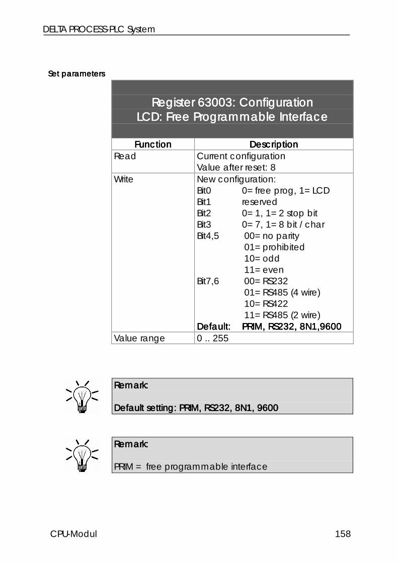
DELTA PROCESS-PLC System
CPU-Modul 158
Register 63003: ConfigurationRegister 63003: ConfigurationRegister 63003: ConfigurationRegister 63003: ConfigurationLCD: Free Programmable InterfaceLCD: Free Programmable InterfaceLCD: Free Programmable InterfaceLCD: Free Programmable Interface
FunctionFunctionFunctionFunction DescriptionDescriptionDescriptionDescriptionRead Current configuration
Value after reset: 8Write New configuration:
Bit0 0=free prog, 1=LCDBit1 reservedBit2 0=1, 1=2 stop bitBit3 0=7, 1=8 bit / charBit4,5 00=no parity
01=prohibited10=odd11=even
Bit7,6 00=RS23201=RS485 (4 wire)10=RS42211=RS485 (2 wire)
Default:Default:Default:Default: PRIM, RS232, 8N1,9600PRIM, RS232, 8N1,9600PRIM, RS232, 8N1,9600PRIM, RS232, 8N1,9600Value range 0 .. 255
Remark:Remark:Remark:Remark:
Default setting: PRIM, RS232, 8N1, 9600Default setting: PRIM, RS232, 8N1, 9600Default setting: PRIM, RS232, 8N1, 9600Default setting: PRIM, RS232, 8N1, 9600
Remark:Remark:Remark:Remark:
PRIM = free programmable interface
Set parametersSet parametersSet parametersSet parameters

CPU Module
CPU Module159
7.3.2.2 Free Programmable Interface Registers (LCD)
Register 63002: Interface StateRegister 63002: Interface StateRegister 63002: Interface StateRegister 63002: Interface State
FunctionFunctionFunctionFunction DescriptionDescriptionDescriptionDescriptionRead Current state
Value after reset: state
Interface stateBit3=1 character lost during
reception, parity error,stop bit error
Bit4=1 reception bufferoverflow
Write Resets error stateValue arnge 0 .. 24
Register 63003: ConfigurationRegister 63003: ConfigurationRegister 63003: ConfigurationRegister 63003: ConfigurationLCD: Free Programmable InterfaceLCD: Free Programmable InterfaceLCD: Free Programmable InterfaceLCD: Free Programmable Interface
FunctionFunctionFunctionFunction DescriptionDescriptionDescriptionDescriptionRead Current configuration
Value after reset: 8Write New configuration:
Bit0=1 0=free prog, 1=Net 2Bit1=1 reservedBit2=1 0=1, 1=2 stop bitBit3=1 0=7, 1=8 bit / charBit4,5 00=no parity
01=prohibited10=odd11=even

DELTA PROCESS-PLC System
CPU-Modul 160
Bit7,6 00=RS23201=RS485 (4 wire)10=RS42211=RS485 (2 wire)
Default:Default:Default:Default: PRIM, RS232, 8N1,9600PRIM, RS232, 8N1,9600PRIM, RS232, 8N1,9600PRIM, RS232, 8N1,9600Value range 0 .. 255
Register 62984: Baud RateRegister 62984: Baud RateRegister 62984: Baud RateRegister 62984: Baud Rate
FunctionFunctionFunctionFunction DescriptionDescriptionDescriptionDescriptionRead Current baud rate
Value after reset: 6Write New baud rate
0 1501 3002 6003 12004 24005 48006 9600 default7 192008 38400
Value range 0 .. 255
Note:Note:Note:Note:
If bit 0 = 1 (Reg 62989) all other bits are vain.If bit 0 = 1 (Reg 62989) all other bits are vain.If bit 0 = 1 (Reg 62989) all other bits are vain.If bit 0 = 1 (Reg 62989) all other bits are vain.

CPU Module
CPU Module161
Register 63004: Transmission BufferRegister 63004: Transmission BufferRegister 63004: Transmission BufferRegister 63004: Transmission Buffer
FunctionFunctionFunctionFunction DescriptionDescriptionDescriptionDescriptionRead Last transmitted character
Value after reset: 0Write Transmit characterValuie range 0 .. 255
Note:Note:Note:Note:
Transmission buffer size 255 characters.Transmission buffer size 255 characters.Transmission buffer size 255 characters.Transmission buffer size 255 characters.
Register 63005: Reception BufferRegister 63005: Reception BufferRegister 63005: Reception BufferRegister 63005: Reception BufferAccess Removes CharacterAccess Removes CharacterAccess Removes CharacterAccess Removes Character
FunctionFunctionFunctionFunction DescriptionDescriptionDescriptionDescriptionRead Received character
Value after reset: 0Write ProhibitedValue range 0 .. 255
Note:Note:Note:Note:
Reception buffer size 255 characters.Reception buffer size 255 characters.Reception buffer size 255 characters.Reception buffer size 255 characters.

DELTA PROCESS-PLC System
CPU-Modul 162
Register 63006: Reception BufferRegister 63006: Reception BufferRegister 63006: Reception BufferRegister 63006: Reception BufferAccess Access Access Access does notdoes notdoes notdoes not Remove the Character Remove the Character Remove the Character Remove the Character
FunctionFunctionFunctionFunction DescriptionDescriptionDescriptionDescriptionRead Received character
Value after reset: 0Write ProhibitedValue range 0 .. 255
Register 62155: Reception Buffer FillingRegister 62155: Reception Buffer FillingRegister 62155: Reception Buffer FillingRegister 62155: Reception Buffer FillingLevelLevelLevelLevel
FunctionFunctionFunctionFunction DescriptionDescriptionDescriptionDescriptionRead Current filling level of the reception
bufferValue after reset: 0
Write prohibitedValue range 0 .. 128
Register 62156: Transmission Buffer FillingRegister 62156: Transmission Buffer FillingRegister 62156: Transmission Buffer FillingRegister 62156: Transmission Buffer FillingLevelLevelLevelLevel
FunctionFunctionFunctionFunction DescriptionDescriptionDescriptionDescriptionRead Current filling level of the
transmission bufferValue after reset: 0
Write prohibitedValue range 0 .. 128

CPU Module
CPU Module163
7.4 Realtime Clock
7.4.1 Overview, Function7.4.1 Overview, Function7.4.1 Overview, Function7.4.1 Overview, Function
A realtime clock is integrated into the PROCESS-PLCDELTA. This real time clock is nonvolatile and notdependent of the RAM buffer battery.
There are 2 register sets with 8 registers each. Register set1 (62920 bis 62927) allows read and write access. Writeaccess to this registers set the time directly. Readaccesses read the time.
Besides, there is register set 2 (62912 bis 62919). This sethas the following meaning: If a program waits for acertain time, no change of the operands (time...) of thecomparison must be guaranteed. Therefore read accessto set 1 copies all data to set 2. There they remainunchanged until a new read access to register 1 occurs(see example).
To set the clock the values are written into set 2 andcompletely transfered to the real time clock by 1 writeaccess to set 1.

DELTA PROCESS-PLC System
CPU-Modul 164
7.4.2 Register Description7.4.2 Register Description7.4.2 Register Description7.4.2 Register Description
Register Set1 Register Set2 Data Rangeread/write read/writedirect buffer
62920 62912 Seconds 0-5962921 62913 Minutes 0-5962922 62914 Hours 0-2362923 62915 12/24h Format 0,12862924 62916 Day of week 1-762925 62917 Day (date) 1-3162926 62918 Month 1-1262927 62919 Year 0-99
Register 62924 62924 62924 62924 has got the following function: the registercontent is Day of WeekDay of WeekDay of WeekDay of Week. 1=Sunday, 2=Monday,3=Thuesday etc.
Register 62923629236292362923 selects between am am am am and pmpmpmpm. Before 12hour mode has to be selected by bit 1 of register 63240.
To display the time in the used format 2222 has to be writteninto special register 61454614546145461454. If this register contains thevalue 2 the sign place of a DISPLAY_REG instruction issuppressed (see example).
Register 63240: Realtime ClockRegister 63240: Realtime ClockRegister 63240: Realtime ClockRegister 63240: Realtime ClockConfigurationConfigurationConfigurationConfiguration
FunctionFunctionFunctionFunction DescriptionDescriptionDescriptionDescriptionRead Current RTC configuration
Value after reset: 0Write Bitcoded register:
Bit 0=1 summer/winter timeBit 1=0 am/pm format
Reg 62924Reg 62924Reg 62924Reg 62924Day of weekDay of weekDay of weekDay of week
Reg 62923Reg 62923Reg 62923Reg 62923selectsselectsselectsselects
am <-> pmam <-> pmam <-> pmam <-> pm

CPU Module
CPU Module165
Bit 1=1 24 hour formatValue range 0 .. 255
7.4.3 Realtime Clock Example Program7.4.3 Realtime Clock Example Program7.4.3 Realtime Clock Example Program7.4.3 Realtime Clock Example Program
The following example program displays the real timeclock data on the user interface.
0: TASK 0 ------------------------------------------1: ;2: REGISTER_LOAD [61454 with 2] ;no sign
3: FLAG 2055;leading zeros4: REGISTER_LOAD [61453 with 6] ;2 places number5: DISPLAY_TEXT [#0, cp=1, "_Current time:"]6: ;7: LABEL 1008: CALL 9009: DELAY 5
10: GOTO 10011: ;12: LABEL 900 ;->DISPLAY13: DISPLAY_REG [#0, cp=25, reg=62925] ;store time14: DISPLAY_TEXT [#0, cp=27, ". .19 , : : "]15: DISPLAY_REG [#0, cp=28, reg=62918] ;month16: DISPLAY_REG [#0, cp=33, reg=62919] ;year17: ;18: ; ------- Display time -------19: ;20: DISPLAY_REG [#0, cp=36, reg=62914] ;hour21: DISPLAY_REG [#0, cp=39, reg=62913] ;minute22: DISPLAY_REG [#0, cp=42, reg=62912] ;seconds23: RETURNEnd of program

DELTA PROCESS-PLC System
CPU-Modul 166
7.5 Operating System Update (Download)
Operating system updates can be realized via theTransferTransferTransferTransfer menu of the SYMPAS programmingenvironment.For this JETTER makes available operating system file ontheir mailbox (extension: *.OSextension: *.OSextension: *.OSextension: *.OS).
Figure 17: Operating system updatescan be realized by the SYMPASprogramming environment
Note:Note:Note:Note:
The timeout time has to be set to 4000 in theSpecial/settingsSpecial/settingsSpecial/settingsSpecial/settings menu for operating system updates.
CPU Module
CPU Module167
IndexIndexIndexIndex
5
50000er numbersAddressing of inputs · 121Addressing the flags · 125Addressing the outputs · 123Addressing the registers · 119Input offset · 135Output offset · 135Register offset · 136
50000er-numbersFlag offset · 135
A
AddressierungIndirect, double indirect · 54
Addressing · 43Digital Inputs · 45Digital outputs · 45Flags · 46Overview · 43Registers · 53
C
Configuration · 3Housings and modules · 4Modules and submodules · 5Slot numbering · 15Submodules of the contr module · 6Submodules of the CPU module · 6
D
Digital inputs · 36Addressing · 45Internal circuit · 37Wiring · 37
Digital outputs · 38Addressing · 45Internal circuit · 39Wiring · 39
E
Earthing · 10EMI · 8
Earthing · 10
F
Flags · 46Overlay of registers and flags · 46Programming with flags · 47Special flags · 48User flags · 46
H
Housing · 4Housings
Mechanical dimensions · 10Housings and modules · 4
I
Inputs digital · 36Instructions
REG · 57; 58REGDEC · 57; 59REGINC · 57; 59REGZERO · 57; 59
InterfaceJETWay-H programming interface · 25
InterfacesJETWay-R · 29Overview · 22Process monitoring interface JETWay-
H · 34Process monitoring interface RS232 ·
33Programming interface · 23User interface · 31
J
JETWay-H · 25; 34Definition PC-card AUTOEXEC.BAT ·
26DIL switch JETWay-H PC-card · 27JETWay-H PC-card · 26Process monitoring interface · 34SYMPAS settings · 28
JETWay-H PC-card · 26AUTOEXEC.BAT · 26DIL switch · 27
JETWay-R · 29
L
LED · 18; 40Digital inputs · 40

DELTA PROCESS-PLC System
CPU-Modul 168
Digital outputs · 41Operating system · 41
M
Maximum expansion · 3Mechanical dimensions · 10Module · 4Modules · 5Modules and submodules · 5
N
Network inteface (JETWay-R) · 29Network operation · 113
Access by 50000er numbers · 119Baud rate · 137Network number · 136; 139N-GET REGISTER · 129N-SEND REGISTER · 128Registers · 131Terminal description · 117
NumberingDigital inputs · 36Digital Outputs · 38Slots · 15
O
Operating system download · 166Outputs digital · 38
P
Power Supply · 18; 21Process monitoring interface · 33Programming interface · 23
Baud rate · 24
R
Real time clockExample program · 165
RegisterIndirect addressing · 54Programming with registers · 54
Registers · 53Calculating with registers · 57Nonvolatile · 53Overlay of registers and flags · 46Special registers · 61
S
Safety instructions · 1Shielding
Earthing · 10Slots
Numbering · 15Special flags · 48Special registers · 61Specifications · 7Submodule of the CPU module · 20Submodules · 5; 20Submodules of the controller module · 6Submodules of the CPU module · 6Switch · 18; 42
T
Technical specifications · 7CPU module · 16Digital inputs · 36Digital outputs · 38EMI · 8
Terminals · 18CPU module · 18
U
User guidance · 79User interface connections · 31User interfaces · 79
Cursor position · 85Display of register contents · 89Flags · 108Overview · 79Programming · 84Query of register values · 91Registers · 95Terminals · 82Text display · 84User input · 91
User Registers · 53

CPU Module
CPU Module169

DELTA PROCESS-PLC System
170