Embed Size (px)
Citation preview

AD-A155 576 NATIONAL PROGRAM FOR INSPECTION OF NON-FEDERAL DAMS /BIRD POND DAN (NA 06.. IUI CORPS OF ENGINEERS WALTNAM
UKLWA* FJ.6 MA NEW ENGLAND DIV APR 80
II

W 132
1111 ',.o ,20
II11 1.25 IA14
MICROCOPY RESOLUTION TEST CIHART
NATIKAAL BUREAU OF STANDARD$-lq63 A
t/
-4I

NEPONSET RIVER BASIN
WALPOLE, MASSACHUSETTS
ID BIRD POND DAM
It MA. 00804
I <
PHASE I INSPECTION REPORTI NATIONAL DAM INSPECTION PROGRAMi
C- py available to D-tC does not
DTIc
__ DEPARTMENT OF THE ARMYNEW ENGLAND DIVISION, CORPS OF ENGINEERS
: WALTHAM, MASS. 02154
DIMTINO0i O sTAT!!L&
p)ISibutio Unlimited
83 31 053

I I IN I A-,- I w n
SECURITY CLAi.'F.-CATION OF THIS PAGE (hmn D te. ,h.,.d)
READ INSTRUCTIONSREPORT DOCUMENTATION PAGE BEFORE COMPLETING FORMI. REPORT NUMBER 2, GOVT ACCESSION NO. 3. RECIPIENT'S CATALOG NUMBER
MA 00804 I5 '7 _ _ _
4. TITLE (andSubtsele) S. TYPE OP REPORT & PERIOD COVERED
Bird Pond Dam INSPECTION REPORT
NATIONAL PROGRAM FOR INSPECTION OF NON-FEDERAL 6. PERFORMING ORG. REPORT NUMBERDAMS ..
7. AUTHOR(&) S. CONTRACT OR GRANT NUMBER(*)
U.S. ARMY CORPS OF ENGINEERSNEW ENGLAND DIVISION
9. PERFORMING ORGANIZATION NAME AND ADDRESS 10. PROGRAM ELEMENT, PROJECT. TASKAREA & WORK UNIT NUMBERS
II. CONTROLLING OFFICE NAME AND ADDRESS 12. REPORT DATE
DEPT. OF THE ARMY, CORPS OF ENGINEERS April 1980NEW ENGLAND DIVISION, NEDED 13. NUMBEROF PAGES
424 TRAPELO ROAD, WALTHAM, MA. 02254 6514. MONITORING AGENCY NAME A ADDRESSIllU dHifeel jeen CWil"hAd Dillce) IS. SECURITY CLASS. (of tis -lporlt)
UNCLASSIFIEDISa. DECL ASSI PIC ATION/DOWNGRADING
SCHEDULE
1I. DISTRIBUTION STATEMENT (el tie Repo)
APPROVAL FOR PUBLIC RELEASE: DISTRIBUTION UNLIMITED
17. DISTRIUUTION STATEMENT (of IA. obetool etered In Weah ". II an..r.. bem Rilect)
IS. SUPPLEMENTARY NOTES
Cover program reads: Phase I Inspection Report, National Dam Inspection Program;however, the official title of the program is: National Program for Inspection ofNon-Federal Dams; use cover date for date of report.
IS. KEY WORDS (Ctteunue O Pevewe side i eeo0ey 0 J0mll64F md t Y 6V Mek Omufbe)
DAMS, INSPECTION, DAM SAFETY,Neponset River Basin
Walpole, Massachusetts
Neponset River
20. ABSTRACT (Contiae on everad aide If n.eeeve meend 6dlip, by bleek someb)
The dam is an 18.5 ft. high, 291 ft. long composite rubble masonry, concrete
and earth embankmeftt. It is small in size with a high hazard potential.The dam is judged to be in generally fair condition because of the seepage
through the left spillway training wall and because the low level outlet has
not been operated in many years and is presumed to be inoperative.
DD , 1473 OITION OiO IS NOVIS ,OSOLETE
1*

Reff46Mi)(rt1 AT 'nV~ f- aREPRODUCED AT GOVERNMI4T EXPENSE
DISCLAIMER NOTICE
THIS DOCUMENT IS BEST QUALITYPRACTICABLE. THE COPY FURNISHEDTO DTIC CONTAINED A SIGNIFICANTNUMBER OF PAGES WHICH DO NOTREPRODUCE LEGIBLY.
40..
lit'; mmm n mmmmmm mmm• m m • m m1

DEPARTMENT OF THE ARMYNEW ENGLAND DIVISION. CORPS OF ENGINEERS
424 TRAPELO ROADWALTHAM. MASSACHUSETTS 02254
REPLY TO i 00StrnlwATTENTION OF:NEDED-E NTIS GR.U
I DTIC TABSU'ianoaod [
SJustitoeati- AR 0 6 1981
Honorable Edward J. KingGovernor of the Commonwealth oi - .t-__ __Massachusetts t ib.... j -
! Availability CodesState House .Boston, Massachusetts ' Avail and/or
t4k-t Special
Dear Governor King:
Inclosed is a copy of the Bird Pind OeA, 4) Pbase I InspectionReport, which was prepared under the National Program for Inspectionof Non-Federal Dams. The report is based upon a visual inspection, areview of past performance, and a preliminary hydrological analysis.A brief assessment is included at the beginning of the report.
The preliminary hydrologic analysis has indicated that the spillwaycapacity for the Bird Pond Dam would likely be exceeded by floodsgreater than 8 percent of the Probable Maximum Flood (FMF), the testflood for spillway adequacy. Our screening criteria specifies that adam of this class which does not have sufficient spillway capacity todischarge fifty percent of the PKF, should be adjudged as having aseriously inadequate spillway and the dam assessed as unsafe,non-emergency, until more detailed studies prove otherwise orcorrective measures are completed.
The term "unsafe" applied to a dam because of an inadequate spillwaydoes not indicate the same degree of emergency as that term would ifapplied because of structural deficiency. It does indicate, however,that a severe storm may cause overtopping and possible failure of thedam, with significant damage and potential loss of life downstream.
It is recommended that within twelve months from the date of thisreport the owner of the dam engage the services of a professional orconsulting engineer to determine by more sophisticated methods andprocedures the magnitude of the spillway deficiency. Based on thisdetermination, appropriate remedial mitigating measures should bedesigned and completed within 24 months of this date of notification.In the interim a detailed emergency operation plan and warning systemshould be promptly developed. During periods of unusually heavyprecipitation, round-the-clock surveillance should be provided.
A
II
F . t. ... .. . . .- --

NEDED-EHonorable Edward J. Kin~g
I have approved the report and support the findings and recommenda-tions described in Section 7, with qualifications as noted above.Irequest that you keep me informed of the actions taken to implementthese recommendations since this follow-up is an important part of thenon-Federal Dam Inspection Program.
A copy of this report has been forwarded to the Department of Environ-mental Quality Engineering, the cooperating agency for the Common-wealth of Massachusetts. This report has also been furnished to theowner of the project, Bird and Sons, Inc., Walpole, Massachusetts.
Copies of this report will be made available to the public, uponrequest to this office, under the Freedom of Information Act, thirtydays from the date of this letter.
I wish to take this opportunity to thank you and the Department ofEnvironmental Quality Engineering for the cooperation extended incarrying out this program.
Sincerekv
CE. E AR, IIIColonel, Corps of EngineersDivision Engineer
j2

BIRD POND DAM
MA-00804
Ii
NEPONSET RIVER BASINWALPOLE, MASSACHUSETTS
PHASE I INSPECTION REPORTNATIONAL DAM INSPECTION PROGRAM
II~II i li lI

NATIONAL DAM INSPECTION PROGRAM
PHASE I INSPECTION REPORT
Identification No.: MA 000804Name of Dam: Bird Pond DamTown: WalpoleCounty and State: Norfolk, MassachusettsStream: Neponset RiverDate of Inspection: 14 April 1980
BRIEF ASSESSMENT
Bird Pond Dam is an 18.5 ft. high, 291 ft. long composite rubble masonry, concrete andearth embankment consisting of a 39 ft. long central spillway, a 132 ft. long earthembankment to the right of the spillway and a 120 ft. long earth embankment to the leftof the spillway. The upstream slopes of both embankments are heavy random rock riprapwith concrete grout. The crest and downstream slopes are grass covered. It is a run-of-the-river dam which is used for storing process water for the Bird & Sons, Inc.Manufacturing Company located on the right abutment and downstream toe of the dam.Three intakes to the mill complex are located in the right abutment area. The spillway
for the dam has a 3 ft. by 2 ft. low level outlet and has provisions for four 5 ft.6 in. high by 5 ft. 3 in. wide stoplog bays and two 5 ft. by 4 ft. spillway suice gates.The crest of the spillway is 8.3 ft. below the top of dam.
The reservoir is about 4,000 ft. long and the surface area of the pond at spillway crestis about 22 acres. The drainage area above the dam is about 25.1 sq. mi., the maximumstorage to top of dam is about 185 acre ft., and the height of the dam is about 18.5 ft.Based on size and storage, the size classification is small. A breach of the dam coulddamage three industrial complexes, with the possibility of loss of more than a fewlives. Therefore, the dam has been classified as having a high hazard potential.Based upon the guidelines the recommended test flood ranges from a PMF to a full PMF.Because of the downstream industrial developments a test flood equal to a full PMF(15,000 cfs) was selected. Since storage is insignificant and inflow is approximatelyequal to outflow, a test flood routing was not performed.
The test flood outflow (15,000 cfs.) would overtop the dam by about 5.7 ft. with stop-logs in place and 5.3 ft. with stoplogs removed. With the stoplogs in place the spill-way can pass about 500 cfs of about 3 percent of the test flood outflow without over-topping the dam. With the stoplogs removed and the spillway sluice gates open thespillway can pass about 2,070 cfs or about 14 percent of the test flood outflow withoutovertopping the dam.
The dam is judged to be in generally fair condition because of the seepage through theleft spillway training wall and because the low level outlet has not been operated inmany years and is presumed to be inoperative. There is brush and tree growth on theleft embankment. Mortar is missing from the joints of the rubble masonry training wallsof the spillway. The concrete spillway service bridge is deteriorated. Minor erosionhas taken place on the downstream slope of the left embankment. There may also be someseepage from the right spillway training wall which at the time of the inspection couldnot be determined because of the high flow conditions.N

Within one year after receipt of this Phase I Inspection Report, the owner, Bird& Son, Inc., should retain the services of a registered professional engineerand implement the results of his evaluation of the following: (1) a detailedhydrologic-hydraulic investigation to assess further the potential for over-topping and the adequacy of the spillway; (2) possible elimination of use ofstoplogs, or modifications to facilitate their quick removal; (3) investigatethe seepage through the left spillway wall; (4) determine if there is anyseepage emanating from the right spillway training wall; (5) inspect the spill-way and stoplog structure during no flow conditions; and, (6) determine the needto relocate two pressure fire hydrants located on the crest of the dam.
The owner should also implement the following operating and maintenance measures;(1) remove trees, root structures and brush growth from the left embankment andbackfill with suitable material; (2) reshape the eroded downstream slope of theleft embankment and provide topsoil and seed; (3) repoint with mortar all voidsin the upstream ends of the rubble masonry spillway training walls; (4) repairspalled and honeycombed concrete in the spillway service bridge deck; (5) deter-mine whether the low level outlet is operative and perform any necessary repairwork; (6) develop a formal surveillance and downstream emergency warning planincluding round-the-clock monitoring during periods of heavy precipitation;(7) institute procedures for an annual technical inspection of the dam and itsappurtenant structures; and, (8) implement a regular periodic maintenanceprogram.
It O/' PETER .
3 DYSON E.0 NO. 8452Q 0
II
'VV

This Phase I Inspection Report on Bird Pond Dam (MA-00804)has been reviewed by the undersigned Review Board sember*. Im ouropinion, the reported findings, conclusions, and recmmendetions areconsistent with the Recomended Guidelilnes for Safety Insection ofDams, and with good engineering judgment and practice, and t herebysubmitted for approval.
./
IVCARNEY M. TERZIAN, MEMBERDesign BranchEngineering Division
RICHARD DIBLIFO 0 E4EWater Control BranchEngineering Division
ARAMAST HAHTESIAN, CHAIRMANGeotechnical Enqineering BranchEngineering Division
APPROVAL RECOIMMNDED:
Chief, %ng4nerLv& Division
!'

PREFACE
This report is prepared under guidance contained in the Recommended Guidelinesfor Safety Inspection of Dams, for Phase I Investigations. Copies of theseguidelines may be obtained from the Office of Chief of Engineers, Washington,D.C. 20314. The purpose of a Phase I Investigation is to identify expeditiously
those dams which may pose hazards to human life or property. The assessment ofthe general condition of the dam is based upon available data and visual inspec-tions. Detailed investigation, and analyses involving topographic mapping, sub-surface investigations, testing, and detailed computational evaluations are be-yond the scope of a Phase I investigation; however, the investigation is intended
to identify any need for such studies.
In reviewing this report, it should be realized that the reported condition ofthe dam is based on observations of field conditions at the time of inspectionalong with data available to the inspection team. In cases where the reservoir
was lowered or drained prior to inspection, such action, while improving thestability and safety of the dam, removes the normal load on the structure andmay obscure certain conditions which might otherwise be detectable if inspectedunder the normal operating environment of the structure.
It is important to note that the condition of a dam depends on numerous and con-stantly changing internal and external conditions, and is evolutionary in nature.
It would be incorrect to assume that the present condition of the dam will con-tinue to represent the condition of the dam at some point in the future. Onlythrough continued care and inspection can there be any chance that unsafe con-ditions be detected.
Phase I inspections are not intended to provide detailed hydrologic and hydraulicanalyses. In accordance with the established Guidelines, the Spillwa', Test Floodis based on the estimated "Probable Maximum Flood" for the region (greatestreasonably possible storm runoff), or fractions thereof. Because of the magni-I tude and rarity of such a storm event, a finding that a spillway will not passthe test flood should not be interpreted as necessarily posing a highly inade-
quate condition. The test flood provides a measure of relative spillway capa-city and serves as an aide in determining the need for more detailed hydrologic
and hydraulic studies, considering the size of the dam, its general conditionand the downstream damage potential.
The Phase I Investigation does not include an assessment of the need for fences,
gates, no-trespassing signs, repairs to existing fences and railings and otheritems which may be needed to minimize trespass and provide greater security forI the facility and safety to the public. An evaluation of the project for com-
pliance with OSHA rules and regulations is also excluded.
It

TABLE OF CONTENTS
Section Pg
Letter of Transmittal
Brief Assessment
Review Board Page
Preface
Table of Contents i
Overview Photo v
Location Map Vi
REPORT
1. PROJECT INFORMATION
1.1 General
a. Authority I
b. Purpose of Inspection
1.2 Description of Project1
a. Location1b. Description of Dam and Appurtenances 1
c. Size Classification 2d. Hazard Classification 2
DaOprao 2
g.Purpose o a
h. Design and Construction History 3i. Normal Operational Procedure 3
1.3 Pertinent Data 3
2. ENGINEERING DATA 7
2.1 Design Data 7
2.2 Construction Data 7
2.3 Operation Data7
2.4 Evaluation of Data 7
ii

Section Page
3. VISUAL INSPECTION
3.1 Findings 8
a. General 8
b. Dam8c. Appurtenant Structures9d. Reservoir Area9e. Downstream Channel9
3.2 Evaluation 10
4. OPERATIONAL AND MAINTENANCE PROCEDURES
4.1 operational Procedures 11
a. General 11
b. Description of any Warning System in Effect 11
4.2 Maintenance Procedures 11
a. General 11
b. Operating Facilities 11
4.3 Evaluation 11
5. EVALUATION OF HYDRAULIC/HYDROLOGIC FEATURES
5.1 General 12
5.2 Design Data 12
5.3 Experience Data 12
5.4 Test Flood Analysis 12
5.5 Dam Failure Analysis 13
6.. EVALUATION OF STRUCTURAL STABILITY
6.1 Visual Observation 15
6.2 Design and Construction Data 15
6.3 Post-Construction Changes 15
6.4 Seismic Stability 15
iii

Section Pg
7. ASSESSMENT, RECOMMENDATIONS AND REMEDIAL MEASURES
7.1 Dam Assessment 16
a. Condition 16
b. Adequacy of Information 16c. Urgency
1
7.2 Recommendations 16
7.3 Remedial Measures 17
a. operation and Maintenance Procedures 17
7.4 Alternatives 17
APPENDIXES
APPENDIX A - INSPECTION CHECKLIST
APPENDIX B - ENGINEERING DATA
APPENDIX C - PHOTOGRAPHS
APPENDIX D - HYDROLOGIC AND HYDRAULIC COMPUTATIONS
APPENDIX E - INFORMATION AS CONTAINED IN THE NATIONALI INVENTORY OF DAMS
I iv

FTI BIRD POND DAM
IIII
OVERVIEW OF DAM FROM RIGHT ABUTMENT
IIII
'IV

102
BIRD PONNDA
DAA
Irv
*~ . C,'- -

PHASE I INSPECTION REPORT
BIRD POND DAM MA 00804
SECTION 1 - PROJECT INFORMATION
1.1 General
A. Authority. Public law 92-367, August 8, 1972, authorized the Secretaryof the Army, through the Corps of Engineers, to initiate a national program ofdam inspection throughout the United States. The New England Division of theCorps of Engineers has been assigned the responsibility of supervising the in-spection of dams within the New England Region. Louis Berger & Associates, Inc.has been retained by the New England Division to inspect and report on selecteddams in the state of Massachusetts. Authorization and notice to proceed wasissued to Louis Berger & Associates, Inc. under a letter of 28 March 1980 fromWilliam E. Hodgson, Jr. Colonel, Corp of Engineers. Contract No. DAC33-80-C-0043has been assigned by the Corps of Engineers for this work.
b. Purpose of Inspection
(1) Perform technical inspection and evaluation of non-federal dams toidentify conditions which threaten the public safety and thus permit correctionin a timely manner by non-federal interests.
(2) Encourage and assist the States to initiate quickly effective dam safetyprograms for non-federal dams.
(3) Update, verify and complete the National Inventory of Dams.
1.2 Description of Project
a. Location. Bird Pond Dam is located in Norfolk County in the Town of
Walpole in eastern Massachusetts. The Pond is an impoundment of the Neponset Riverand is located about 15.5 miles upstream from the mouth of the Neponset River at itsconfluence with the Atlantic Ocean. The Pond is located just upstream of theWashington Street Bridge over the Neponset River. The dam is shown on U.S.G.S.Quandrangle, Norwood, Massachusetts with coordinates approximately at N 420 09' 46"1,
W 710 13' 05".
b. Description of Dam and Appurtenances. Bird Pond Dam is a run-of-the-riverdarn believed to have been originally constructed in the late 1700's. The presentdam is a 1906 reconstruction of the original dam and provides process water for Bird& Son, Inc. a manufacturing company with buildings located at the toe of the darn andon the right abutment. The dam is about 291 ft. long, about 18.5 ft. high, andessentially consists of a 39 ft. long composite masonry and concrete gravity over-flow section with earth embankments on each side of it. The crest of the overflowsection is 8.3 ft. below the top of the dam.
The embankment to the right of the spillway is about 132 ft. long and 15 ft. wideat its narrowest point. The embankment to the left of the spillway is about 120 ft.
long and the crest width varies from about 18 ft. at the spillway to about 20 ft.at the left abutment. The downstream slopes of both embankments are about 1horizontal to 1 vertical and are sod covered. The upstream slopes are of random rockriprap covered with concrete grout. A paved roadway is located along the toe of theleft embankment and downstream slope of the right embankment.

A rubble masonry wall about 365 ft. long extends from the right abutment upstreamalong the south reservoir rim. The outlet facilities for the dam are located alongthis wall.
The 39 ft. long spillway consists of rubble masonry training walls and a concretesillblock along the crest of a sloping downstream apron. There are provisions forfour 63 in. wide and two 60 in. wide stoplog bays along the crest of the spillwayas well as two 60 in. by 48 in. spillway sluice gates. A 3 ft. by 2 ft. low leveloutlet is located about 17.3 ft. below the top of the dam. At the downstream toeof the spillway a concrete culvert carries flow under the paved roadway and themill buildings to the Neponset River (See Appendix C photographs).
Along the south reservoir rim there are three outlet facilities used only to supplyprocess water to the mill buildings. The approximate location of these outletpipes, all reported to be in operating condition, is shown on Drawing B-i, AppendixB. A 48 in. dia. pipe leads from the reservoir to a holding tank in the mill build-ing on the shoreline. Several outlets from the holding tank provide water forvarious purposes. There are also 18 in. dia. and 20 in. dia. pipes with gatevalves. The location of the gate valves is shown on drawing B-1. These outletpipes provide condenser cooling water and process water. Since all three of theseoutlets connect into closed systems they could not be used as a means to empty thereservoir.
c. Size Classification. Bird Pond Dam has a hydraulic height of about 18.5ft. above downstream river level, and impounds a normal storage of about 113 acre-ft. to spillway crest level and a maximum of about 185 acre-ft. to top of dam. Inaccordance with the size and capacity criteria given in Recommended Guidelines forSafety Inspection of Dams, the project falls into the small category on the basisof height and storage and is therefore classified accordingly.
d. Hazard Classification. The Neponset River immediately below the dam flowsthrough a closed culvert that passes under a service road and two mill buildings.About 600 ft. below the dam a twin masonry arch structure carries the river underWashington Street. It is estimated that this restriction would reduce the breachflood surge downstream of Washington Street by as much as 58 percent and therebycause severe flooding of the mill complex located just downstream of the dam. Inthe reach beyond Washington Street the river passes over another dam located in amill complex about 1500 ft. below Bird Pond Dam. It is estimated that the stageon this second dam would rise by about 6 ft. as the flood surge passed through thissecond mill complex and the dam would be overtopped. About 4,400 ft. below BirdPond Dam the river passes through a third mill complex. It is estimated that atthis point the water surface would rise about 4 ft., causing damage to the millcomplex. It is estimated that the additional depth of flooding due to the breachdischarge could be as much as 12 ft. at the first mill site, about 4 ft. at thesecond mill site, and about 2 ft. at the third mill site downstream. Under thespillway full conditions it is estimated that only the first mill site would beflooded and the depth of flooding under those conditions would be about 2 to 3 ft.Beyond this third mill the river passes through an urban area for a distance ofabout 7,000 ft. however, in this area the river is wider and flooding should notbe as severe. Beyond this urban development the flood plain widens out signifi-cantly and the flood surge should subside in this reach without causing furtherdamage.
A sudden failure of the dam could therefore cause the loss of more than a few livesand result in appreciable industrial economic losses. Consequently, Bird Pond Damhas been classified as having a high hazard potential, in accordance with the
Recommended Guidelines for Safety Inspection of Dams.
e. Ownership. Bird Pond Dam is owned by Bird and Sons, Inc. of Walpole,Massachusetts.
2-L

f. Operator. Mr. Ross Fallon, Plant Manager, Bird and Sons, Inc., WalpoleMassachusetts. Telephone: 668-2500.
g. Purpose of Dam. The dam impounds water used for processing in the indus-trial buildings located just downstream of the dam and along the right rim of thereservoir.
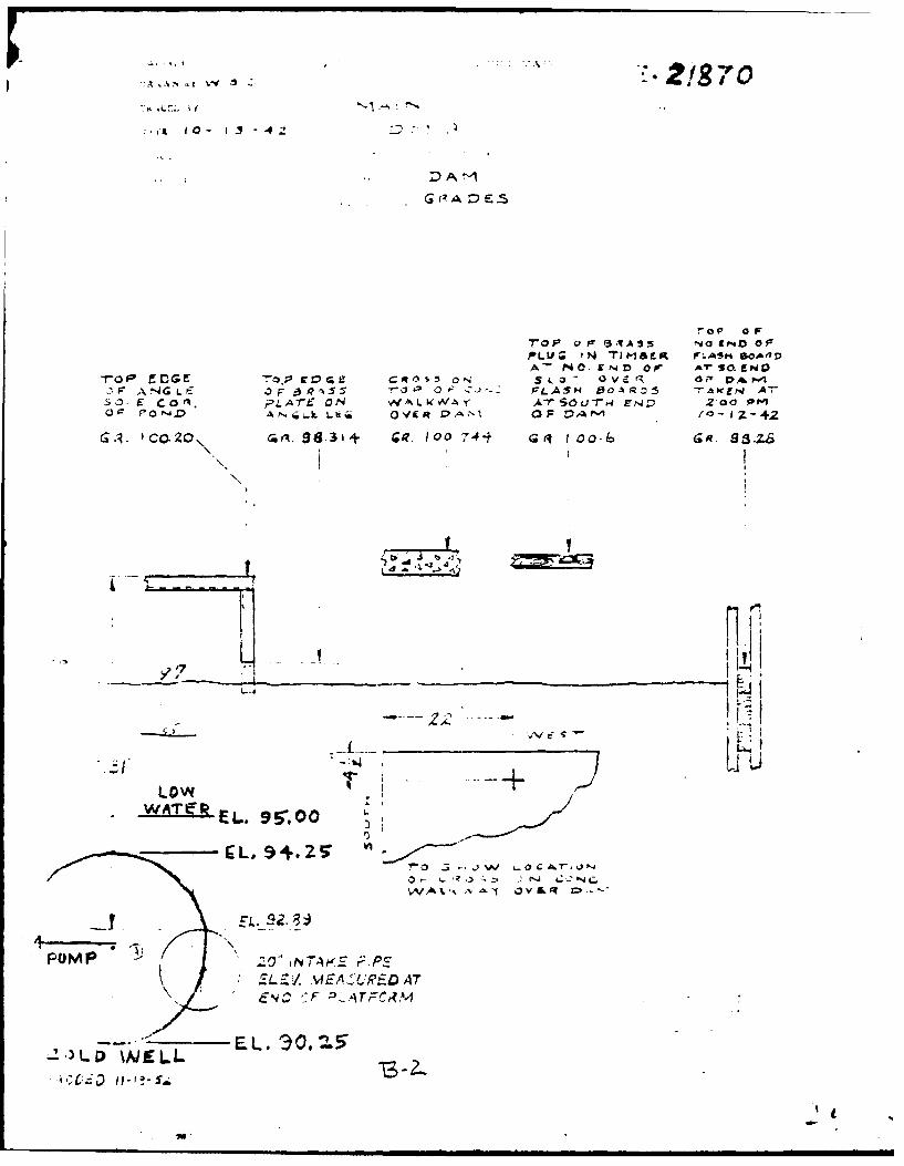
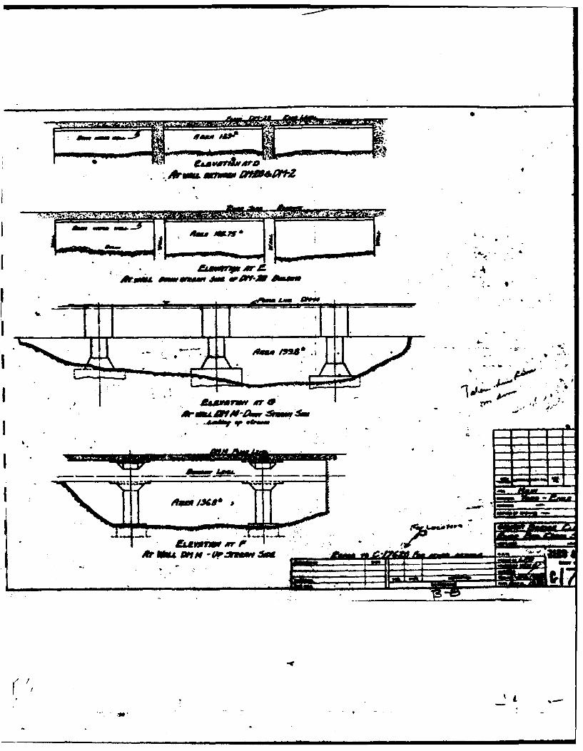
h. Design and Construction History. No information is available regardingdesign and construction of the original 17th century dam. Several drawings of the1906 reconstruction were recovered and indicate that at the spillway section aconcrete wall was built against the face of the upstream masonry wall; the presentservice bridge was constructed about 15 in. above the top of the old bridge; a newstoplog structure and planks were added; the fixed spillway sill was lowered about9 in.; and, the downstream rubble block apron was grouted with concrete. Thedesigns for the spillway were prepared by Edward A. Buss, Engineer, Boston, Mass.
i. Normal Operating Procedure. According to the owner's representatives thewater level in the pond is maintained at or above elevation 98.2 so as to provideprocess water for the mill's operation. The facility is also operated in conjunc-tion with several other manufacturers located along the Neponset River. Each ofthese other manufacturers also require specific water levels for their operations.Therefore, all of the dam operators along the Neponset River work together tomaintain various water levels for each of the other manufacturers.
1.3 Pertinent Data
a. Drainage Area. The drainage area above Bird Pond Dam consists of about25.1 sq. mi., described in general as a flat and coastal area. The basin consistsof two major subdrainage areas: one extending northerly and drained by Mine Brook;the other extending southerly and drained by the upper reaches of the Neponset River.The northerly drainage area is predominately forested and has a scattered population.The southerly drainage area consists of woodlands, open fields, swamps, and highlydeveloped urban areas. The Neponset Reservoir is located in the upper reaches ofthe southerly drainage area. It has a drainage area of about 1.5 sq. mi. and wouldhave only a slight effect on the inflow to Bird Pond.
b. Discharge at Damsite
(1) Outlet Works Conduit. The low level outlet works for Bird Pond Dam is a2 ft. high by 3 ft. wide sluice gate located in the center of the overflow sectionof the dam at about elevation 86.7 ft. The gate is presumed to be inoperative. Itis estimated that if operative, the low level facility would be capable of dischargingabout 120 cfs with the water surface level in the pond at the top of dam elevation 103.9.
(2) Maximum Known Flood at Damsite. The maximum discharge at the damaite isunknown. It is reported tht during the floods of August 1955 the water surfaceof the pond reached the crest of the dam's earth embankments and that sand bagswere placed along the crest to prevent overtopping of the dam.
(3) Ungated Spillway Capacity at Top of Dam. With the stoplogs in place andthe spillway sluice gates closed the spillway capacity at top of dam, elevation 103.9,is 505 cfs. With all stoplogs pulled and the two spillway sluice gates open thespillway capacity at top of dam is 2,070 cfs.
(4) Ungated Spillway Capacity at Test Flood Elevation. With the stoplogs inplace and the spillway sluice gates closed the spillway capacity is 2,550 cfs attest flood elevation 109.6. With all stoplogs pulled and the two spillway sluicegates open the spillway capacity is about 4,000 cf a at a test flood elevation of
109.2.
3

( G
(5) Gated Spillway Capacity at Normal Pool Elevation. Not applicable.
(6) Gated Spillway eapacity at Test Flood Elevation. Not applicable.
(7) Total Spillway Capacity at Test Flood Elevation. With the stoplogs in
place and the spillway sluice gates closed the total spillway capacity is 2,550 cfsat a test flood elevation of 109.6. With all stoplogs pulled and the two spillway
sluice gates open the total spillway capacity is 4,000 cfs at a test flood elevationof 109.2.
(8) Total Project Discharge at Top of Dam. Whereas the low level outlet ispresumed to be inoperative the total project discharge with stoplogs in place and thespillway sluice gates closed is 505 cfs at elevation 103.9. With the stoplogs pulledand spillway sluice gates open the total project discharge is 2,070 cfs at elevation103.9.
(9) Total Project Discharge at Test Flood Elevation. The total project dischargeis 15,COO cfs at test flood elevation 109.6 with the stoplogs installed and spillwaysluice gates closed. The total project discharge is 15,000 cfs at test flood elevation109.2. with the stoplogs pulled and the spillway sluice gates open.
c. Elevation (ft. N.G.V.D.)
(1) Streambed at toe of dam - 85.4
(2) Bottom of cutoff - unknown
(3) Maximum tailwater - unknown
(4) Recreation pool - not applicable
(5) Full flood control pool - not applicable
(6) Spillway crest - 95.67 without stoplogs - 101 with stoplogs
(7) Design surcharge (Original Design ) - unknown
(8) Top of Dam - 103.9
(9) Test flood surcharge - 109.6
d. Reservoir (length in feet)
(1) Normal pool - 4,000 ft.
(2) Flood control pool - not applicable
(3) Spillway crest pool - 4,000 ft.
(4) Top of dam - 4,000 ft.
(5) Test flood pool - 4,ooo ft.
e. Storage (acre-feet) I
(1) Normal pool - 113 I(2) Flood control pool - not applicable
4

(3) Spillway crest pool - 113
(4) Top of damn - 185.5
(5) Test flood pool - 370
f. Reservoir Surface (acres)
(1) Normal pool - 22
(2) Flood-control pooi - not applicable
(3) Spillway crest - 22
(4) Test flood pool - 38.1
(5) Top of darn - 27.5
g. Dam
(1) Type - Concrete overflow section with non-overflow earth embankments.
(2) Length - 291 ft.
(3) Height - 18.5 ft.
(4) Top Width - Right embankment -, !1Sf tLeft embankment - 18 ft. to 20 ft.
(5) Side Slopes - Downstream - 1.5 horizontal to 1 vertical. Upstream unknown.
(6) Zoning - Unknown
(7) Impervious Core - Unknown
(8) Cutoff - Unknown
(9) Grout Curtain - Unknown
h. Diversion and Regulating Tunnel - Not applicable
i. Spillway
(1) Type - 6 Bay, concrete overflow section.
(2) Length of weir -6 bays having an effective hydraulic width of 31 ft.
(3) Crest elevation -With stoplogs - 101.0
Without stoplogs - 95.67
(4) Gates - 2 - 5' wide x 4' high sluice gates elevation 95.67
(5) U/s Channel - Natural river channel
(6) D/S Channel - Closed conduit with natural bottom which passes under millbuildings.
5I

j. Regulating Outlets
(1) Invert - 86.7
(2) Size - 3 ft. wide x 2 ft. high
(3) Description - Rectangular sluice gate
(4) Control Mechanism - Hand operated
(5) Other -Presently the gate is inoperative

SECTION 2 -ENGINEERING DATA
2.1 Design Data
No data on the design of the dam or appurtenances has been recovered. During thecourse of the inspection several plans showing the 1906 reconstruction of thespillway were obtained and copies are included in Appendix B.
2.2 Construction Data
No records or correspondence regarding construction of the damn have been found.There are however contractors logs of the grouting of the spillway training wallsin 1979.
2.3 Operation Data
According to the owner's representative the water level in the pond is maintained ator above a specific elevation so as to provide process water for the mills operations.The facility is however operated in conjunction with several other manufacturerslocated along the Neponset River who also require specific water levels for theiroperations.
2.4 Evaluation of Data
a. Availability. Since no engineering data ia available, it is not possible tomake an assessment of the safety of the dam. The basis of the information presentedin this report is principally the visual observations of the inspection team.
b. Adequacy. The lack of in-depth engineering data did not allow for a definitivereview. Therefore, the adequacy of this dam could not be assessed from the standpointof reviewing design and construction data, but is based primarily on visual inspection,past performance history and sound engineering judgement.
c. Validity. Not applicable
7

SECTION 3 - VISUAL INSPECTION
3.1 Findings
a. General. The visual inspection of Bird Pond Dam took place 6n 14 April1980. On that date the water was about 0.9 ft. above the top of the soplogs or6.4 ft. above the spillway crest. The discharge was estimated to be ab ut 87 cfs.There was no evidence of major problems, but a few items require attenti n (seesection 7.3). The dam was judged to be in only fair condition because of\theseepage through the left spillway training wall and because the low level \outlet issaid not to have been operated in 20 years and is presumed to be inoperativ.
b. Dam. The dam is a run-of-the-river dam with an overall length of ahout291 ft. It currently provides process water for a manufacturing company locat~edin part on the south reservoir rim and the remainder immediately downstream of\thedam. The present dam is a 1906 reconstruction of the original dam which was bu 'ltin the 1700's.
The dam basically consists of a 39 ft. long gravity concrete and masonry spillway, \a 132 ft. long earth embankment to the right of the spillway and a 120 ft. long \earth embankment to the left of the spillway. The dam has a hydraulic height ofabout 18.5 ft.
The right embankment is of fairly uniform section and is about 15 ft. wide at itsnarrowest point. A paved roadway is located along the toe of the left embankmentand across the downstream slope of the right embankment. Heavy random rock riprapcovered with concrete grout protects the upstream slope of the embankment. A con-crete retaining wall which is in good condition supports the paved roadway acrossthe lower downstream slope while the upper downstream slope is aboutl vertical toI horizontal and is grass covered. There was no evidence of any seepage along thedownstream toe of the right embankment. The right embankment appears to be in goodcondition. (See Appendix C, photo nos. I and 2.)
The left embankment is about 120 ft. long and the crest width varies from 18 ft. atthe spillway to about 20 ft. at the left abutment. The upstream slope is coveredwith heavy random rock riprap grouted with concrete. The crest of the embankmentis sodded. The 1 vertical to 1 horizontal downstream slope is also sodded exceptfor a section to the left of a fence near the left abutment. In this area thedownstream slope is quite irregular and light brush growth and at least 6 treesapproximately 1 ft. in dia. are well established. There are also four trees locatedto the right of the fence along the downstream slope. The sodded downstream slopeto the right of the fence has some areas that have minor erosion. In general theleft embankment appeared to be in fairly good condition (See Appendix C, photonos. 3 & 4).
An MDC sewer line built in the 1930's cuts diagonally across the left abutment fromthe road to the left of the left abutment and heads into the factory area immediatelydownstream of the dam. There is a manhole at the toe of the embankment approximately20 feet to the left of the fence line where the fence line intersects the downstreamtoe and there is a sewer manhole on the crest of the embankment. At the time of theinspection there was no evidence of any problems with the sewer line.
Two fire hydrants connected to the municipal water supply system are situated on topof the dam. The pressure line connecting the two hydrants is in the reservoir alongthe upstream slope of the dam. Check valves for the supply line are located at theroadvay along the left abutment of the dam.
8
.n i ,,m..,..,nn. mmimli i.2L I

c. Appurtenant Structures. The overflow section or spillway of the dam isa concrete siliblock with a sloping downstream apron. Both the left and rightspillway training walls are constructed of approximately 2 ft. thick rubble masonrywith mortared joints. There is also a central concrete pier dividing the spillwayinto two separate bays (see Appendix C, photo nos. 5 & 6). Both the rubble masonrytraining walls and central concrete pier are in deteriorated condition with lossof mortar from joints and considerable spalling. Seepage was emanating from severaljoints of the left training wall. Because of the numerous seeps and the high flowover the spillway at the time of inspection it was not possible to estimate thequantity of seepage. It also appeared that there might be some seepage from theright training wall; however, the high flow over the spillway at the time of in-spection made it difficult to clearly establish whether seepage exists (seeAppendix C, photo No. 12).
Surmounted on the concrete siliblock of the spillway is a 5 ft. 6 in. high stoplogstructure. Each of the spillway bays has provisions for 2 stoplogs bays and 1spillway sluice gate 5 ft. wide by 4 ft. high. Because of the high flow at thetime of inspection the condition of the stoplog structure could not be determined.However, discussions with the owner's representatives indicate that it is wellmaintained and that the stoplogs are removed frequently in anticipation of heavyrunoffs.
A 2 ft. by 3 ft. low level outlet is located in the center of the spillway structureabout 17.3 ft. below the top of the dam. It is said not to have been used in thepast 20 years and it is doubtful whether it is operative according to the owner'srepresentative.
There is a concrete slab service bridge across the spillway bays. From this servicebridge the stoplogs are removed and the 5 ft. by 4 ft. sluice gates are operated.Because of the extensive honeycombing and spalling of the concrete, the servicebridge is judged to be in poor condition. (See Appendix C, photo Nos. 13 & 14.)
Along the south reservoir rim there are three outlet facilities used only to
supply process water to the mill buildings. The approximate location of these
outlet pipes is shown on Drawing B-1, Appendix B. At the junction of the em-
bankment with the right abutment there is a 20 in. dia. outlet pipe with gate
valve. This outlet pipe was reported to be in operating condition. About 105
ft. upstream of this outlet pipe there is another intake structure. Here an
18 in. dia. and a 48 in. dia. pipe provide process water for the manufacturing
company. These outlet facilities were also reported to be in operating condi-
tion (see Appendix C, photo No. 7). Since all three of these outlets connect
into closed systems they could not be used as a means to empty the reservoir.
d. Reservoir Area. The reservoir behind the dam is a ponding of the
Neponset River. The shoreline around the reservoir appears to be stable with no
evi dence of slides, movement or distress. Along the south reservoir rim from
the right abutment and extending upstream about 365 ft. is a rubble masonry wall
(see Appendix C, photo No. 11).
e. Downstream Channel. At the downstream toe of the spillway apron a con-crete culvert which is in fair condition carries flows under two roadways and two
buildings (see Appendix C, photo No. 8). The culvert emerges about 300 ft. down-stream of the dam into the Neponset River. About 300 ft. beyond this point theriver passes under a twin masonry arch bridge carrying Washington Street over the
Neponset River (see Appendix C, photo Nos. 9 & 10). About 1,500 ft. below Bird

Pond Dam the Neponset River flows over a second dam and a mill complex. Athird mill complex is located about 4,400 ft. downstream of Bird Pond Dam.Beyond this third mill complex the Neponset River widens and passes through anurban area for a distance of about 7,000 ft. before entering a large swampy area.
3.2 Evaluation
In general, the visual inspection adequately revealed key characteristics of thedam as they may relate to its stability and integrity, permitting an assessmentto be made of those features affecting the safety of the structure. Minor erosionof the downstream slope of the left embankment was evident. Brush growth andseveral mature trees are well established on the left embankment. Mortar was miss-ing from the spillway training walls and the central concrete pier is deteriorated,as is the spillway service bridge. Seepage was noted from the left spillway train-ing wall and possibly from the right training wall as well. The low level outlethas not been used in 20 years and is presumed inoperative. High flow over thespillway at the time of inspection made it difficult to clearly establish whetherseepage exists through the right spillway training wall. There is no regularperiodic maintenance program. For these reasons the Dam was judged to be infair condition.
10
t

SECTION 4 - OPERATIONAL MAINTENANCE PROCEDURES
4.1 Operation Procedures
a. General. The dam is owned and operated by Bird & Son, Inc. According
to the owner's representatives the water level in the pond is maintained at orabove elevation 98.2 so as to provide process water for the mill's operations.
The low water elevation for providing process water is 5.7 ft. below the top ofdam. The facility however is operated in conjunction with several other manu-
facturers located along the Neponset River who also require specific water levels
for their operations.
b. Descriotion of any arning System in Effect. NIc warning system is ineffect at Bird Pond Dam.
4.2 Maintenance Procedures
a. General. No regular periodic maintenance pzogram is in effect at BirdPond Dam. There are however several items which require periodic maintenance suchas: the upkeep of sod on the crest and downstream slope of the dam; the removal ofgrowth from the left end of the embankment; the removal of debris from the spillwayopening and from the downstream culvert opening; the upkeep of the spillway servicebridge; the repair of the spillway training walls; the maintenance of the stoplogstructure; the surveillance of the embankment regarding seeps; and, the maintenanceof the outlet gates.
b. Operating Facilities. The low level outlet below the spillway has notbeen used for many years. It is questionable whether it is still operative.There are three outlet pipes, 18 in., 20 in., and 48 in. dia. and gate valvesused to supply process water to the mill buildings. These are all reported to bein operating condition. The stoplogs are normally removed in anticipation of
high runoffs.
4.3 Evaluation
Overall maintenance of the dam is generally good. Specific maintenance items areevaluated as follows: The sod on the crest of the dam is in good condition whilethe downstream slope is only fair condition; brush and trees are well establishedon the left end of the embankment and need to be removed; the spillway and down-stream culvert opening are relatively free of debris; the spillway service bridgeis in poor condition; there is seepage through the spillway training walls andthey are in a deteriorated condition; the stoplog structure is in fair condition;no embankment seeps were evident; and, the outlet gates except for the low leveloutlet are in operating condition. The owner should establish a formal warningsystem for the dam in the event of an emergency.
I
I
11

SECTION 5 - EVALUATION OF HYDRAULIC/HYDROLOGIC FEATURES
5.1 General
Bird Pond Dam is a run-of-the-river type project, which furnishes process waterto a mill located on the right bank and below Bird Pond. It is basically a lowstorage - high spillage facility. It consists of a concrete overflow section withstoplogs and two sluice gates and earth embankmens on either side of the overflowsection. The dam impounds a normal storage of about 113 acre-ft. with provisions foran additional 72 acre-ft. of capacity in its surcharge space to top of dam. Withstoplogs installed the spillway is capable of discharging about 500 cfs with thesurcharge to the top of the dam. The general characteristics of the 25.1 sq. mi.drainage basin is best described as flat and coastal. The northern part of thedrainage area is predominately forested while the southern part consists of woodlands,open fields, swamps, and highly developed urban areas. The Neponset Reservoir islocated in the extreme upper reaches of the southern part of the drainage area.
5.2 Design Data
No hydrologic or hydraulic design data was retrieved for Bird Pond Dam.
5.3 Experience Data
During the field inspection it was reported by the owner's representative that duringthe August, 1955 flood the stage of the pond reached the crest of the dam's earthembankments and that sand bags were placed on the crest to prevent overtopping ofthe dam. U.S.G.S. Gaging Station 01105000 is located about 8,000 ft. downstreamof the dam on the Neponset River. The gaging station has a period of record datingback to October 1939 and Water Supply Papers for the gage show that the maximumrecorded discharge at the gage site was 1,490 cfs on August 19, 1955 when the gageheight was 14.65 ft. The drainage area above the gage is 35.2 sq. mi. compared witha drainage area of 25.1 sq. mi. above Bird Pond Dam.
5.4 Test Flood Analysis
Bird Pond Dam is about 18.5 ft. high and impounds about 185 acre-ft to the top ofdam and is therefore classified as small in size. Because of downstream conditions,the hazard potential is classified as high. In accordance with Recommended Guide-lines for Safety Inspection of Dams, the recommended test flood range is one halfthe probable maximum flood to a full probable maximum flood (PMF). Because of theurban development downstream, the magnitude of the test flood selected as mostclosely relating to the involved risk was a full PMF.
The NED March 1978 Preliminary Guidelines Memorandum for Estimating Probable Dis-charges was used for estimating the probable maximum flood peak flow rate. From theFlat and Coastal Regions Curve the test flood discharge was determined to be about 600CSM or about 15,000 cfs.
Two discharge curves for the dam were computed (see sheets D-5 thru D-8). Onecurve was computed assuming the stoplogs to be in place and this spillway sluice-gates closed as found on the day of inspection, the other curve was computed assum-ing the stoplogs to be removed and the two spillway sluice gates open. Reservoirarea and storage capacity curves and tables are shown on sheets D-3 and D-4,Appendix D. For determining surface areas and surcharge capacities, planimeteredareas were taken from contours delineated on U.S.G.S. 2000 ft. per inch quadranglesheets. However, because of the discharge and low storage capability of thefacility, a test flood routing was not performed.
12

Relative pond water surface, elevations are shown below for the two spillways conditions.
Height of WaterSpillway Flood Water Surface over top of dam Discharge
Condition Magnitude Elevation in ft. in cfs
Stoplogs PMF 109.6 5.7 15,000in place (Test Flood)
Stoplogs PMF 107.4 3.5 7,500in place
Stoplogs PMF 109.2 5.3 15,000Removed (Test Flood)GatesOpen
Stoplogs PMF 106.8 2.9 7,500RemovedGatesOpen
From the above table it can be seen that the project will not pass the test
flood without overtopping the dam for either spillway condition. With the stop-logs in place the project can handle only about 3 percent of the test flood with-out overtopping the embankments. With the stoplogs removed and the two spill-ways sluice gates open the project can pass about 14 percent of tile test floodwithout overtopping the embankments. It should be noted that the water surfaceelevation at the time of the test flood could be higher because of the down-stream channel capacity.
5.5 Dam Failure Analysis. A breach owing to structural failure of the dam orby piping or sloughing is a possibility. For this analysis a breach was assumedwith the water level at the top of dam. The "rule of thumb" method suggestedin the Corps of Engineers' March 1978 Guidance Report was used for the breachanalysis. With a breach width equal to about 100 ft., an outflow of about13,900 cfs, including 500 cfs from the spillway would be realized. (See SheetsD-10 thru D-14, appendix D).
Immediately below the dam the Neponset River flows in a closed system for about300 ft. as it passes under a service road and two mill buildings. At a point600 ft. downstream of the aam a twin masonry arch structure carries the riverunder Washington Street. It is estimated the Washington Street roadway re-striction would reduce the downstream breach flood surge by as much as 58 per-cent and would cause severe flooding of the mill complex located just below thedam. About 1,500 ft. below the Bird Pond Dam is a second mill complex with a damfacility. It is estimated that the rise in head on this second dam would be about6 ft. because of the breach and portions of the mill facility would suffer damages.About 4,400 ft. below the dam is a third mill complex where it is estimated thatthe breach would cause a rise in water surface of about 4 ft. It is estimated thatthe additional depth of flooding due to the breach discharge could be as much as12 ft. at the first mill site, about 4 ft. at the second mill site, and about 2ft. at the third mill site downstream. Under the spillway full conditions it isestimated that only the first mill site would be flooded and the depth of floodingunder those conditions would be about 2 to 3 ft. In the next reach of the riverfor a distance c.f 7,000 ft. the river continues to pass through relatively heavy
13
wn

urban developments. However, the river is wider in this reach and flooding shouldnot be as severe. Beyond this urban development the flood plain widens out sig-nificantly and the flood surge should subside in this reach without further damagingeffects.
in summary, a breach of the dam could cause flood damage to three industrial com-plexes, with the possibility of the loss of more than a few lives. (Appendix D,Sheet D-15, shows the area of potential flooding.)
1.4

SECTION 6 - EVALUATION OF STRUCTURAL STABILITY
6.1 Visual Observations
There are no design calculations, as-built drawings or other data which would permitthe preparation of structural stability computations. The dam is now stableand is in fair condition. Deficiencies described below and in section 7 should becorrected.
The field investigation revealed the following:
(1) Seepage through the left masonry spillway training wall and possiblythrough the right training wall.
(2) Need for repointing mortar in the joints of the upstream ends of themasonry spillway training walls.
(3) Need for repair of the spalled and honeycombed spillway service bridgedeck.
(4) Brush and tree growth on the left embankment.
(5) Minor erosion of the downstream slope of the left embankment.
6.2 Design and Construction Data
No plan or calculations of value to a stability assessment are available.
6.3 Post-Construction Changes
The only records of any post-construction changes made to the embankments or thespillway are of the 1906 reconstruction of the spillway. There are also limitedrecords of cement grouting of the spillway training walls where they intersect theembankments. This grouting was done in 1979 and was an attempt to eliminate seepagethrough both the left and right spillway training walls.
6.4 Seismic Stability
The dam is located in Seismic Zone NO. 2 and in accordance with recommended Phase IIguidelines does not warrant seismic analysis.

SECTION 7
ASSESSMENT, RECOMMENDATIONS AND REMEDIAL. MEASURES
7.1. Dam Assessment
a. Condition. On the basis of the Phase I visual examination, Bird Pond Damappears to be in generally fair condition because of the seepage through the leftspillway training wall and because the low level outlet has not been operated inmany years and is presumed inoperative. The deficiencies revealed indicate thata further investigation should be carried out and that some remedial work is needed.The major concerns of the overall integrity of the dam are as follows:
(1) The spillway can only pass 3 percent of the test flood outflow.
(2) The dewatering facility is inoperative.
(3) There is seepage through the left spillway training wall and possibly throughthe right training wall.
b. Adequacy of Information. The lack of in-depth engineering data did not allowfor a definitive review. Therefore, the adequacy of this dam could not be assessedfrom the standpoint of reviewing design and construction data, but is based primarilyon visual inspection, past performance history and sound engineering judgement.
c. Urgency. The recommendations and remedial measures enumerated below shouldbe implemented by the owner within one year after receipt of this Phase I InspectionReport.
7.2 Recommendations
It is recommended that the owner should retain the services of a registered profes-sional engineer experienced in the design of earth dams to make investigations andstudies of the following, and if proved necessary, to design appropriate remedialworks.
(1) Make a detailed hydrologic-hydraulic investigation to assess furtherthe potential for overtopping and the adequacy of the spillway.
(2) Review the use of stoplogs on the spillway crest and determine the feasibilityof either eliminating their use altogether, or modifying them to facilitate their quickremoval in anticipation of a storm.
(3) Investigate the cause of the seepage through the left spillway training wall.
(4) Determine whether there is seepage through the right training wall.
(5) Inspect spillway and stoplog structure during a period of no flow con-
ditions.
(6) Determine the need to relocate two pressure fire hydrants located on thej crest of the dam.
(7) Remove trees, root structures and brush growth from the left embankmentand backfill with suitable material.

7.3 Remedial Measures
a. Operating and Maintenance Procedures.
(1) Fill all holes in the embankment with suitable material.
(2) Reshape the eroded downstream slope of the left embankment and providetopsoil and seed.
(3) Repoint with mortar all voids in the upstream ends of the rubble masonryspillway training walls.
(4) Repair spalled and honeycombed concrete in the spillway service bridge deck.
(5) Determine whether the low level outlet is operative and perform anynecessary repair work.
(6) Develop a formal surveillance and downstream emergency warning plan,including round-the-clock monitoring during periods of heavy precipitation.
(7) Institute procedures for an annual periodic technical inspection ofthe dam and its appurtenant structures.
(8) Implement a regular periodic maintenance program.
7.4 Alternatives
There appear to be no feasible alternatives to the above recoummendations.
171

APPENDIX A
INSPECTION CHECKLIST
moo

VISUAL INSPECTION CHECKLIST
PARTY ORGANIZATION
PROJECT Bird Pond Dam DATE April 14, 1980
TIME 1:00 PM
Owner: Bird & Son, Inc. WEATHERCloudy
W.S. ELEV. 101.9 U.S. NA DN.S.
PARTY: A/E Representatives Owner's Representatives
I. Peter B. Dyson 6. Ross Fallon - Plant Manager
2. Pasquale E. Corsetti 7. James Moylan - Project Engineer
3. Roger F. Berry 8. John Hayes - Dam Operator
4. Carl J. Hoffman 9.
5. William S. Zoino 10.
PROJECT FEATURE INSPECTED BY REMARKS
1. Hydrologic Roger F. Berry LBA
2. Hydraulics/Structures Carl J. Hoffman LBA
3. Soils & Geology William S. Zoino GZA
4. General Features Peter B. Dyson LBA
5. General Features Pasquale E. Corsetti LBA
6.
7.
8.
9.
10.
LBA - Louis Berger & Associates, Inc.
GZA - Goldberg & Zoino & Associates, Inc.
, , i i L

PERIODIC INSPECTION CHECKLIST
PROJECT Bird Pond Dam DATE April 14, 1980
PROJECT FEATURE Embankment Dam NAME William S. Zoino
DISCIPLINE Geotechnical NAE__
AREA EVALUATED CONDITIONS
DIKE EMBANKMENT
Crest Elevation 103.4
Current Pool Elevation 101.9
Maximum Impoundment to Date Unknown
Surface Cracks None
Pavement Condition N/A
Movement or Settlement of Crest None
Lateral Movement None Noted
Vertical Alignment Good
Horizontal Alignment Good
Condition at Abutment and at Generally good. However, spillway trainingConcrete Structures walls are in poor condition on upstream end
Indications of Movement of Evidence of grouting of voids behind spill-Structural Items on Slopes way training walls at intersection with
embankmentsTrespassing on Slopes None
Sloughing or Erosion of Slopes Noneor Abutments
Rock Slope Protection - Riprap Riprap is in good condition but is veryFailures irregular.
Unusual Movement or cracking at Noneor near Toes
Unusual Embankment or Downstream None Noted
Seepage
Piping or Boils None Noted
Foundation Drainage Features None evident
Toe Drains None
Instrumentation None

PEIODIC INSPECTION CHECKLIST
PROJECT Bird Pond Dam DATE April 14_ jqRO
PROJECT FEATURE Spillway NAME Roger F. Berry
DISCIPLINE Hydraulics/Structures NAME Carl J. Hoffman
AREA EVALUATED CONDITIONS
OUTLET WORKS - SPILLWAY WEIR. APPROACHAND DISCHARGE CHANNELS
a. Approach Channel
General Condition Good
Loose Rock Overhanging Channel none
Trees Overhanging Channel none
Floor of Approach Channel unknown
b. Weir and Training Walls
General Condition of Concrete fair
Rust or Staining yes
Spalling yes
Any Visible Reinforcing yes
Any Seepage or Efflorescence yes - both walls
Drain Holes unknown
c. Discharge Channel
General Condition fair
Loose Rock Overhanging Channel none
Trees Overhanging Channel none
Floor of Channel unknown
Other Obstructions none

P-ERIODIC INSPECTION CHECKLIST
PROJECT Bird Pond Dam DATE April 14, 1980
PROJECT FEATURE Spillway Bridge NAME________________
DISCIPLINE Structures NAME Carl J. Hoffman
AREA EVALUATED CONDITIONS
OUTLET WORKS - SERVICE BRIDGE
a. Superstructure All concrete
Bearings N/A
Anchor Bolts N/A
Bridge Seat N/A
Longitudinal Members poor
Underside of Deck poor
Secondary Bracing N/A
Deck deteriorated
Drainage System N/A
Railings fair
Expansion Joints N/A
Paint N/A
b. Abutment & Piers
General Condition of Concrete poor to fair
Alignment of Abutment good
Approach to Bridge good
Condition of Seat and Backwall fair

PERIODIC INSPECTION CHECKLIST
PROJECT: Bird Pond Dam DATE: 14 April 1980
AREA EVALUATED CONDITIONS
Outlet Works - Control Tower N.A.
Outlet Works - Intake Channel N.A.and Intake Structure
Outlet Works - Transition and Conduit N.A.
Outlet Works - Outlet Structure and N.A.Outlet Channel
'1

APPENDIX B
ENGINEERING DATA
II

ed,, 0 , --- IT, r teVhe
dj- e± -&j a92 Cb om /b v - G £ ,/ve (apj~o, LC at,
Se''rLfetcratofdo', atC. -S~ a/ -t "b
RAprap wlh, conc 9v* '25',reboavat AS / A'~ ol/' /8'0 itah.e
top ~ ~ '~O 7
PLA N
,op A 9 '-o/e' pfo J-o,.'/ desr fronSe0re.
5 4-14,
$4'b/owe -
-) klWatr way llo'de,-~Ah//f bva"n~
I ' C r s E l / 0 q a r o . L9 g
El S567
EFABAAKA'T CROSS SEC 7/ON 3SP/LLWAY- PROPI11f
APPENDIX 4
BIRD PONO RESERVOIP DAMfPG
Vy2/7
roP o FrO P 0 F 5 T A 3 No 110OF
PLUi t 9N Ti MDEL FLAISH 00aafl.A-MO. END~, OF SO. END
'I F A -4G L1 ?- F 3.4q%5S -r,00 '0 '- - FLASH 00o3R:)5 -r K --so. E con p.Are ON YsLWWAY A-rsouirk END 2:00 %PPA0~ 'O"AJD At-. L~Qe ~N OF DAt- /0- 1 Z-42
G.I. 'COa2O Gn,98.31+ CI100 74+ GR~ I004, G 5
LOW 777WATe IEL. 95.00
-~~ L..5
23L IELL

g l;!A-7~ /--
U,
.24 '7V Aj~,6r-~-'A' ~-~
3 -1 0 7 H ~ ,A~rA ~P~~(~s./-e. 'R~--
~ f-fl/3 2 ~ /0 z)6f~ ~ ,'74 ''~
/ //-/~~ ~ 1.5 ~24 6.5/-?- ~ 7p/ )> -~
r V/A~ I~. A, .; Ir 0
/..d 'fr' /0 .2Y 9 o'~/?Z - ~-s> i /~~
(l-'q 05lrt~q0>' Z
221//i 1140'~&~j Qr~ Z
A01 0_1_Ai~~~j -
~~~~~~a~~~- L:4 7- S'~~?,,- 5/d3

II'60'
I *IO
44Aw
I.4Aw A &~~'
'. & 1.
ir

IIN
" .. .. - ; 7. ..- . .
_::-:.,. ... . * -S . - .o .' . - -" * .
• . - .- ." " - " " " " : :
" " ' ' " '- " , .5 . '%4 * t" ,' " " s € . ,, , * . N ,, ; . . . _
a ' ,,4 * 1'' " '" -5 <• . , " [ ... .- , .-
j4p
.. -:I .. ,, . . . . . . .'
* ; ... I, .,,. . -.... ,
,, " , :. .- - . --.. . .- -. . , ..., . _ :
C.: i . I. .. . " . .: _ • .- __
* .i : : ' l .; _ ' " " 5 . I"• • " • .- ' ; - : . . ,: .J '.- -. ° " , :d - ." .- - ' " .. .. .
;A's.
,o, ,L-............
OAfu 7iO-
-t DM , D A M
Z.,4

05ALi-- or Reroe'74fric on r,
Abe ,w' -wp
t.-
IK
p"f
TVPP'fP"f~

fOP ReCePoMe'~Ct&,. 1 at AiV7,71. ,ve~ywwww'"E~w.
Fr

Xlef-r 1001" -.FBQ i
Af.
is
Mo~d ppWMI MMSMVV P ea A~arr~l -o P-
*ja ~ di "o~p IV 1 "Ife *
'pier
$~-Z4' 00AdW. t

W -biNrd 9r eop&..
ZC%?APAWA Ast v-gpjwm
W.S9W WA. CP laa poae
A~o mor.*,a d..
~-. vpe.m~to i, c

Ora%& - Aw -A - -A-
-
144
IONAAIA&WrA- A- Da
*WOW a .W.
Amm- a- s A.
IAreAwItvJw -W. w
- *- M.A -A-- L- -h -
-AdI d4 O & O a
PM-
ifr&ww or-~~u
or IO AV vp 4"Mord" .

*, v b. . .4
,.
.
,*
k
Ipp L I. PH,-. Fs
...
d0.4f .
.,..
* -.
" •.
- 71
._ _ . , -, -- * . 1,
+ ,
--
t'
" ; '
- - r
,- /
, ' ° - 1-
p
F .. LJ .... . 7ij <
- "-.. . . .".
' I.- .
.. . . ... I
, . - 1'
I .. .. ,-.
- ...*.':
---- 4u- L. 4.
......
. .
-L -"
__I."
---*. nllmnn
al i a -ilnn -

*IWO ~d .6-r
4,-a
* .W%./$A.d.
A' S - .
jT}) 7AW
4 w.4~t.&~, -- 144
\. ~ -- ~ / idisc *~.dwIS
"L. Alt
I- P--Y-
*ZrII i r ON
-5*sVeff.*4&v - A0
-d DA B- 02

P it -,q 4 r a
77 fw f
0 * ~A..
a R.AA~z .4 - .*J~.jr J'A -(M

-A --.-- --.---
ik ~ V'7.~ .
AL r* i
~ ~-A
C AYI 1 4 b 9;hq -L.d&,
2--.. it1A~4 4
*~~d*O.' ' *. -Yy-$-
Cv.' .. 9- y -6
~ ~~, Z LA rZ 4
-1 A -,4
C*1fV l -,V
1'' kv I-
-f 4,pwAW.04 fZ i. VJG"I.MA !-p.1
U77_____ _____ __49
-aP AO b- 4 9A
0*B 26922*A P -4 *1 ,.1L'.

APPENDIX C
PHOTOGRAPHS

?W-fV. Amp al I" IS Mal~
.- ~ NATIONAL PRIOGRIAM OF INS C TION of N
BIRD POND DAM
SKE'CH Pt.AN SHOWING LOCi
ORI ENTATION OF PHOTO
.._.,
WQO~~~~~ PONl E~V/ PA
I | rl, I ,,I, .PA

BIRD POND DAM
1. View of crest and upstream slope of dam from right abutment
2. View of downstream slope of dam from right abutment
C-2

BIRD POND DAM
3. Minor erosion on downstream slope of dam and mature tree near left spillway wall.
4. Minor pothole on downstream slope of left embankment
C-3

B-IRD POND DAM
5. View of right spillway bay from toe Of
dam
6. view of left Spill"YbYfomteo a
C-4

BIRD POND DAM
"big-
7. Bird Pond outlets along rubble masonry wall on south reservoir rim
8. Downstream end of spillway apron and entrance to culvert under mill buildings
c-5
w NI - -I N Iin-
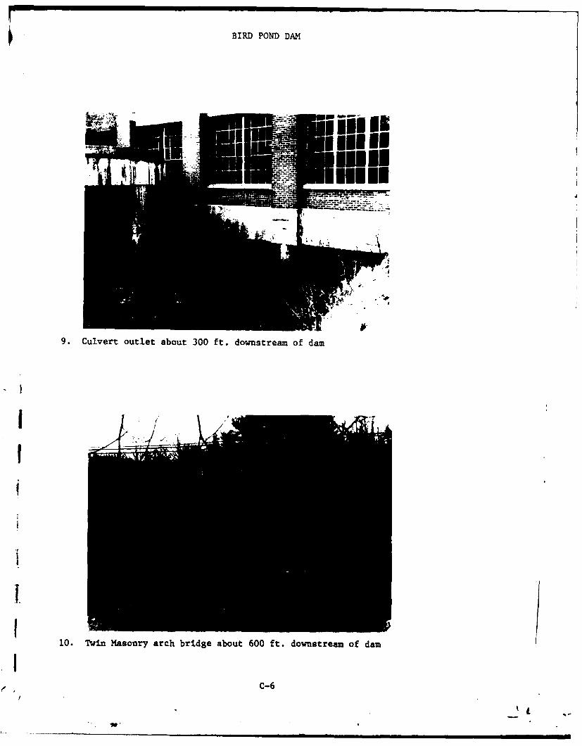
BIRD POND DAM
9. Culvert outlet about 300 ft. downstream of dam
IIZ
I /
10. Twin Masonry arch bridge about 600 ft. downstream of dam
IC-6
• '1

BIRD POND DAM
11. Rubble masonry wall along south reservoir rim
12. Seepage through left training wail of spillway
C-7I

BIRD POND DAM
13 ptemfc fdtroae oceesa vrsila
13. Dowsteam face of deteriorated concrete slab over spilway
1II1
1~II
APIENDIX D
HYDROLOGIC AND HYDRAULIC CONPUTATIOUS
I
'I'it
I-.
V

SY~DA~~:~ LOUIS BERGER & ASSOCIATES INC. SHEET NO.---I-----OF
CHM BY.___ DAT ---- - ------- PROJECT
46-e80 -71 * 5 ___
37,67 3.
-2 534%.&Zi~
MI I # 3404
less kc at

sy~L-AE3'~ LOUIS BERGER & ASSOCIATES INC. SHEET ,-Z---O
C9.S----AE-----Z M ----- PROJET2L±a5---
Actw y LvV %r4 \kcO
* 1: D-2

my ~~ DATE ~ o LOUIS BERGER & ASSOCIATES INC. SHEET NO.--------O.-'
mHO Y --- DATE ----- IN' _Q± PROJET--\- - - --- -- -- -- -- --- -- -- -- --
___ __ - _ __ CT SWr5oQ.At -i:
102. 2,q 2Z -:. '3120 2S1 24ALF 24-9 4
IA 27.7 24,6 s-h 9 -:5
B (c 314- -1 !Z cl 24-7141c07 -35 ,53 z _k.32,4 2-79
ics 35, 342 3A.2 1-
3se 2-74
* 0-3

In
- 4I .-F I. 1-t- -4- t
4 - - - - - - .

a n14c
x-0II!!Ii~5z 3.~~~~~~~~ -AC2 *. 4~ __ ~
L~~~ TO L U
A- 0 2 ' , %C e fe 0 K
0 la 4) 31 0 aCOwl..29~o 0 ic
b~4-b .5 z. 15. Ca3 70 .4 (a IR S
6 H0 5.r, ea W1 374 4 1sla 1.1 4111 1I Z2r. 6 12.9 *8 21 14 454 45 1177 W2 721 ), 425
0 25 4 S,5 33$6 IS 4,1 4561 Sl -1 z7.z 1 -37 6,1 s5<4 140 4.1 3 4. .0
4 I -

a n'x
MC 45fmar P4WuCLa B*wsSua 0- --- - - -
4; 4,0 4q97441 ~o
4, 749
0.( 0S, Tn l4zAW0 11
_-S I 1,5 l ~ 6%a 8- 2Z
9-61 200 046 34.4 9.83 ipia- W0.7 4t0 I' 27?
1021 14,35 3631 0, 469 -% 03 7a A0

I I l
D..__ ,.._- :.) LOUIS BERGER & ASSOCIATES INC. SHEET N2- OF.-__
C HK.. UY..._ DATR \ ,- A- AS -- -V- - - --------- PROJECT__.._K --------
qm 7 96I
)e
R670 Sbc~
t10 W,"5)2 ,7o
i ~~9 \7,707 : 5
I
50!5 207c
lQ6 6 50$47c
200 444c
II
I -
.... 4

T. T
x Tii
o of
98
wT.

D ~ g AT~E O LOUIS BERGER & ASSOCIATES INC. SHEET NO.- ------ OF
CHC BY- - AE---Airp __~ A ---- PROJEC_ J - ----
-- w ~ i w -------- - ------
A -& 06 Gcz A.ws i r . \ v c % 4
WoL ~5I~T'~MAYAQ~PM F;LoA1L
Z5\ -7
(, j~D-9

.YJ1~..OATA#.~~LOUIS BERGER & ASSOCIATES INC. SHEET NO
CNKD. mY-.......ATC ---- -- v ------ PROJECT W 1su m J KT - . FiA!M l ---4 ------------------
A-S5um ZAA V~Lk WUFI4 %AIF7.~ L.'4 : AiV--_fQ
4mit% A PA vAx' 0 Qt
vo w~. 5'I =r&
s6 A04% 7 vL 2 .12o=i
-Aa51
.ri- A z
S- l c'bocm'.P
~+O~ Q~4cps
"TwP4A%,.s aA as~~w

Wl .S....AT:2:OLOUIS BERGER & ASSOCIATES INC. SHEET .- ; --OFCMKO. MY...-----DATE ------- ±t---- PROJECT --W:!g
--
ITat ac I. %kqoqr4c47UI AOn-8\ r
,qL~ 3 CaZ5 it23 6
IVA Ps(zr-a) S7qc.
I SI
I AI
D-1

Y. D E__ _,,.,. -e: LOUIS BERGER & ASSOCIATES INC. SHEET NO._3 ....- OF_ _C: KO.. SY ------ -DATE .... ---- -- -- A - P. . t PROJECT__V_.n __ : -------
i
cA.
suac. __ _ _ _ __ A4iA .*~
.
;:i L IL 6/Zi
~B 45.Oa a a. ao
2
Ca-2-.-4-S----c--mw-----
/r4lac.

,Y.._..__ _ oDAT..A2 .. - LOUIS BERGER & ASSOCIATES INC. SHEET NO,,,o._ -- .... &.2
CHKO. ,,....DATE ----- ------ PROJECT K -------
2 \ Q .' \., .
Ca 5 . 543 3.26 M01 126-4 78E9 3'47 52
A rrA -4\
-_ 4 4
-7 if
I A
I # 0 1
. -- - - - - - - - - - - - - - - - - -
4423-
2 - •$ ,,- , -1
zil

*Y,....EL.oAT_..A-.. "'LOUIS BERGER & ASSOCIATES INC. SHEET ,0__L ---- OF__CHKD. BY. ..... DATE ------. --- - -------- PROJECT---'"-gcr ----- --
SUSJ(-T MA z
~~iiA&~\4 A~4 41,
su 9__a .. 3._._.._, .. : V.._ _____ A ,-_ .__
n. j 44 - z:
2.
\014
C ~ - ~

_ _ _ __ _ _ AINAG
f~~ 7 2
N5
olK
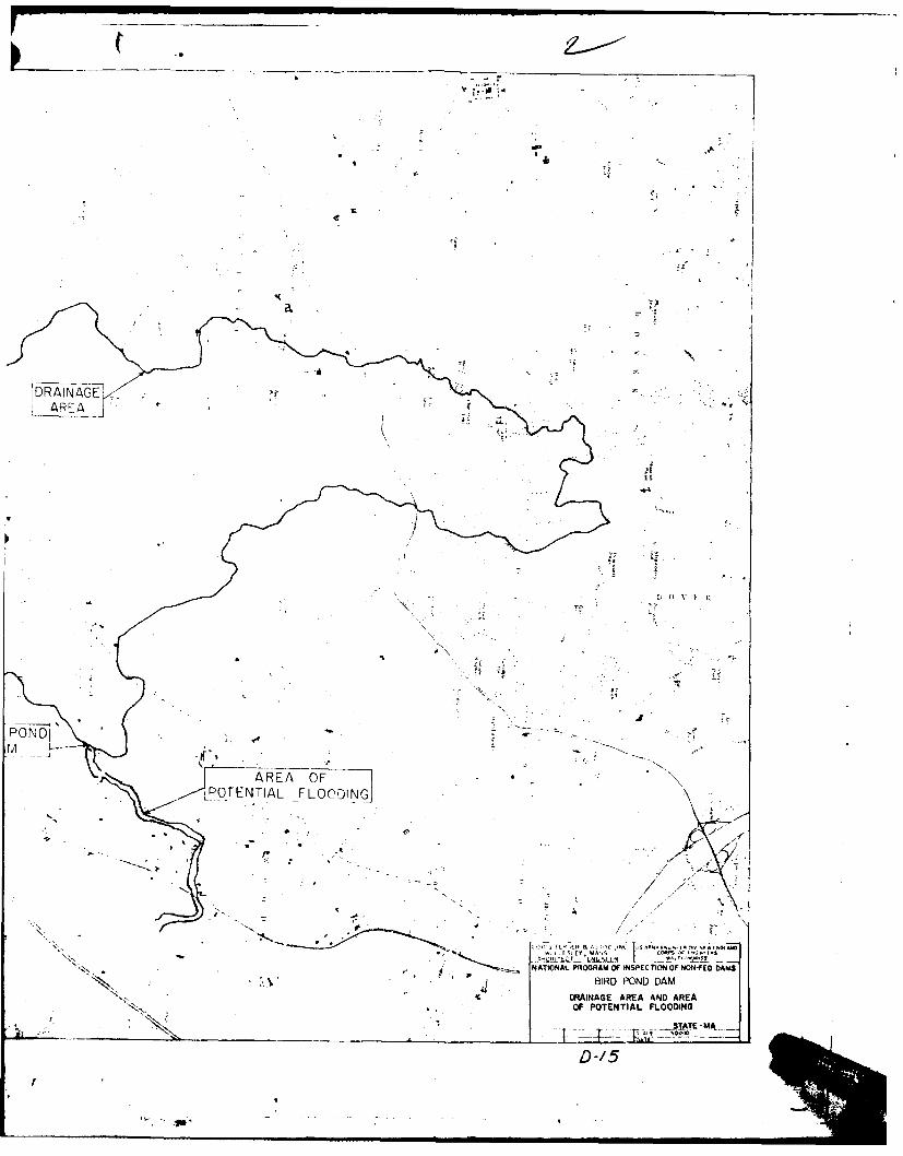
bDRAiNAGE>AREA
POND'
AREA OF
OF POTENTIALFLOODING
T llz .- ,
ND 1

94.
/0
DRANAG AEA NDAREA O9M POOF POTENTIAL FLOODING
44'C~N J SCL0:00

APPENDIX E
INFORMATION AS CONTAINEDIN THE
NATIONAL INVENTORY OF DAMS

7AE ATITUDE L04GITUDE REPORT CATE~.0,.,~O STATI FOAT Cen tm COUT NAMET I WSIDA
I I . 0!0 H WS) GY v 4
. 021 qo oID F'ON , DAM Io 0o . _ _7_1J
PONLAR NAM[ NAM[ C0 IMPOUNDMENT
1 ' RNEAREST DOWNSTREAM O s
lS R'ROR SREAMCITY-TOWN-VILLAGI p MU, Vi A
L1 1 07 01 -S, T 4 1 V F 4 AAL___________
TYEAR T DRAU- ;,POUNCIN CAACT(ES 1
TYPE OFODAM ICOMPLETED PURPOSES rt T "A ' .- J _-4--t .- j- *JO $ T 0sN -E N ,S A V /C
lnCI I r- 113: NED N
RE'JARKS
r 71 . -A; _____ -- NVGAIN OK
s. ILWAY ., VOLUME POWER CAPACITY NAVIGATION LOCKS'L ASA AS~~"GE OF OAM j"~%r
I c I RI: ; I300 I
OWNER ENGINEERING BY I CONSTRUCTION BY
REGULATORY AGENCY
DESIGN CONSTRUCTION I OPERATION MAINTENANCE
oISPccTION OATEA INSPCTION BY IDAY.Mo, Y . AUTOITY FOR INSPELTIC*J
LOJI bElER ,4 ASSCC P-C -7~u: j L9;P. Wh
L. REMARKS
IL

A


![الكلمات المكنونة العربية...˘ ˘ˇ ˜MMMOV^bS F MMMˇ‘$ MMM#$ ˛MMM˛ˇaU]] ^S RS TR MMMZ_WMMMXSS R^UVW M MMX ˜YMMMZ W MMM[" VMMMˇ\$]SS SSRRRRRR]U R ^ U ]MMM#N](https://img.dokumen.tips/doc/110x75/5e5bbc4ad53cd05c95188155/f-f-oemmmovbs-f-mmma.jpg)