Embed Size (px)
Citation preview
Warning: (1) Periodic inspection and maintenance of Liquid Controls Group products is essential. (2) Inspection, maintenance and
installation of Liquid Controls Group products must be made only by experienced, trained and qualified personnel. (3) Maintenance,
use and installation of Liquid Controls Group products must comply with Liquid Controls Group instructions, applicable laws and safety
standards (such as NFPA Pamphlet 58 for LP-Gas and ANSI K61.1-1972 for Anhydrous Ammonia). (4) Transfer of toxic, dangerous,
flammable or explosive substances using Liquid Controls Group products is at user’s risk and equipment should be operated only by
qualified personnel according to applicable laws and safety standards.
Installation, Operation& Maintenance Manual
ZV200 Bypass Valve
Model ZV200 Bypass Valve
IH106B

WarningInstall, use and maintain this equipment according to Corken’s instructions and all applicable federal, state, local laws
and codes. Periodic inspection and maintenance is essential.
Corken One Year Limited WarrantyCorken, Inc. warrants that its products will be free from defects in material and workmanship for a period of 12 months
following date of purchase from Corken. Corken products which fail within the warranty period due to defects in material
or workmanship will be repaired or replaced at Corken’s option, when returned, freight prepaid to Corken, Inc., 3805
N.W. 36th Street, Oklahoma City, Oklahoma 73112.
Parts subject to wear or abuse, such as mechanical seals, vanes, piston rings, packing and other parts showing signs
of abuse are not covered by this limited warranty. Also, equipment, parts and accessories not manufactured by Corken
but furnished with Corken products are not covered by this limited warranty and purchaser must look to the original
manufacturer’s warranty, if any. This limited warranty is void if the Corken product has been altered or repaired without
the consent of Corken.
All implied warranties, including any implied warranty of merchantability or fitness for a particular purpose, are expressly
negated to the extent permitted by law and shall in no event extend beyond the expressed warranty period.
Corken disclaims any liability for consequential damages due to breach of any written or implied warranty on Corken
products. Transfer of toxic, dangerous, flammable or explosive substances using Corken products is at the user’s risk.
Such substances should be handled by experienced, trained personnel in compliance with governmental and industrial
safety standards.
Contacting The FactoryBefore you contact the factory, note the model number and serial number of your pump. The serial number directs us to
a file containing all information on material specifications and test data applying to your specific pump. When ordering
parts, the Corken service manual or Installation, Operation and Maintenance (IOM) manual should be consulted for the
proper part numbers. ALWAYS INCLUDE THE MODEL NUMBER AND SERIAL NUMBER WHEN ORDERING PARTS.
The model and serial numbers are shown on the nameplate of the unit. Record this information for future reference.
Model No.
Serial No.
Date Purchased
Date Installed
Purchased From
Installed By
2
Table of ContentsApplicable Notice for ATEX Conformity .......................................................................................................................... 4
Installation and Operation of Your Bypass Valve ............................................................................................................ 5
Appendix A
Model Number and Identification Code ...................................................................................................................... 7
Appendix B
Technical Specifications and Performance ................................................................................................................. 8
Appendix C
Outline Dimensions ...................................................................................................................................................... 9
Appendix D
Parts Details ............................................................................................................................................................... 10
Appendix E
Troubleshooting Guide ................................................................................................................................................11
Appendix F
Storage of the ZV200 Bypass Valve ...........................................................................................................................11
3
Applicable Notices for
ATEX 94/9/EC ConformityProduct Type:
Corken Liquid Transfer Bypass Valves
Model covered: ZV200
Intended Application:
The bypass valve models covered by this manual
conform to the European Union ATEX 94/9/EC Directive
for explosive gas atmospheres and transfer of liquefied
gases such as Liquefied Petroleum Gas, anhydrous
ammonia, freons, etc.
Possible Misuse Warning:
The designated bypass valve models must only be
installed in systems designed for its intended use, similar
to the examples presented in this manual.
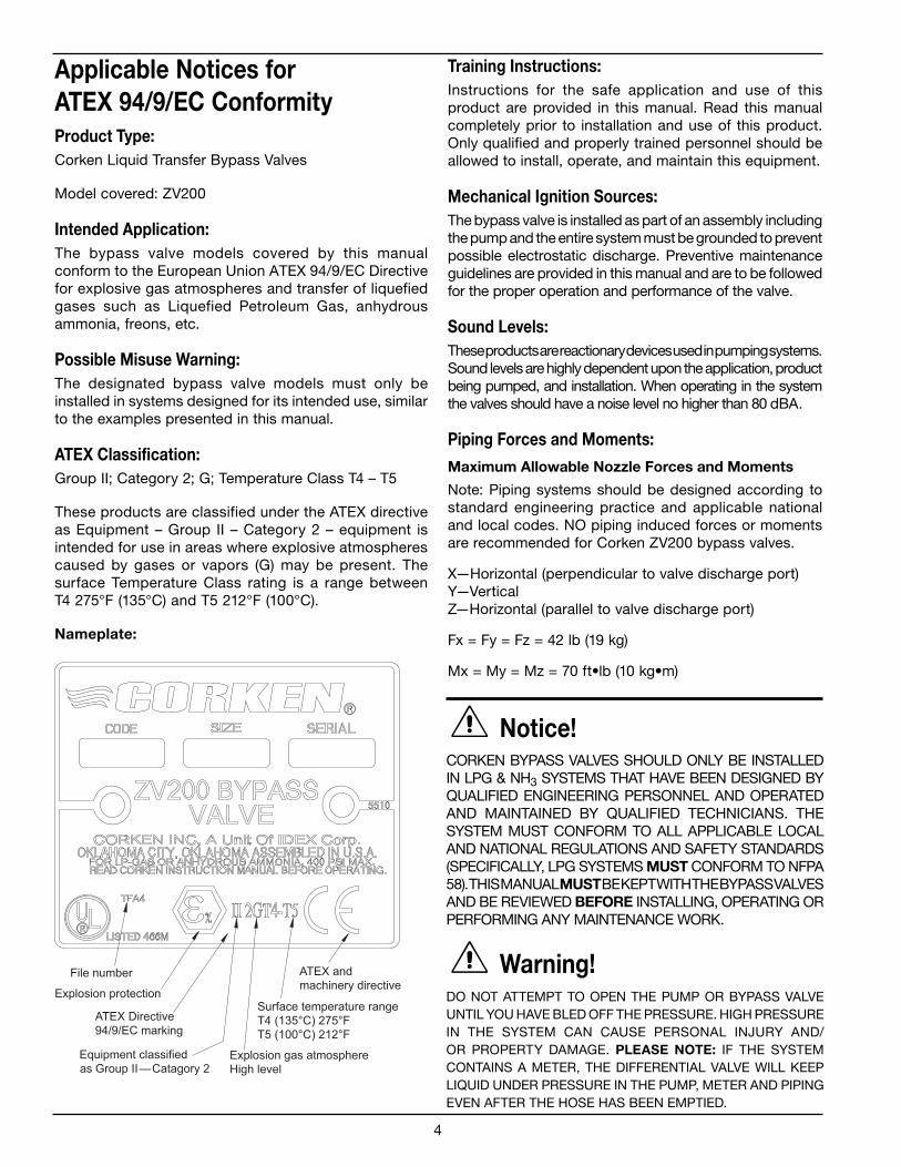
ATEX Classification:
Group II; Category 2; G; Temperature Class T4 – T5
These products are classified under the ATEX directive
as Equipment – Group II – Category 2 – equipment is
intended for use in areas where explosive atmospheres
caused by gases or vapors (G) may be present. The
surface Temperature Class rating is a range between
T4 275°F (135°C) and T5 212°F (100°C).
Nameplate:
Training Instructions:
Instructions for the safe application and use of this
product are provided in this manual. Read this manual
completely prior to installation and use of this product.
Only qualified and properly trained personnel should be
allowed to install, operate, and maintain this equipment.
Mechanical Ignition Sources:
The bypass valve is installed as part of an assembly including
the pump and the entire system must be grounded to prevent
possible electrostatic discharge. Preventive maintenance
guidelines are provided in this manual and are to be followed
for the proper operation and performance of the valve.
Sound Levels:
These products are reactionary devices used in pumping systems.
Sound levels are highly dependent upon the application, product
being pumped, and installation. When operating in the system
the valves should have a noise level no higher than 80 dBA.
Piping Forces and Moments:
Maximum Allowable Nozzle Forces and Moments
Note: Piping systems should be designed according to
standard engineering practice and applicable national
and local codes. NO piping induced forces or moments
are recommended for Corken ZV200 bypass valves.
X—Horizontal (perpendicular to valve discharge port)
Y—Vertical
Z—Horizontal (parallel to valve discharge port)
Fx = Fy = Fz = 42 lb (19 kg)
Mx = My = Mz = 70 ft•lb (10 kg•m)
Notice!CORKEN BYPASS VALVES SHOULD ONLY BE INSTALLED
IN LPG & NH3 SYSTEMS THAT HAVE BEEN DESIGNED BY
QUALIFIED ENGINEERING PERSONNEL AND OPERATED
AND MAINTAINED BY QUALIFIED TECHNICIANS. THE
SYSTEM MUST CONFORM TO ALL APPLICABLE LOCAL
AND NATIONAL REGULATIONS AND SAFETY STANDARDS
(SPECIFICALLY, LPG SYSTEMS MUST CONFORM TO NFPA
58). THIS MANUAL MUST BE KEPT WITH THE BYPASS VALVES
AND BE REVIEWED BEFORE INSTALLING, OPERATING OR
PERFORMING ANY MAINTENANCE WORK.
Warning!DO NOT ATTEMPT TO OPEN THE PUMP OR BYPASS VALVE
UNTIL YOU HAVE BLED OFF THE PRESSURE. HIGH PRESSURE
IN THE SYSTEM CAN CAUSE PERSONAL INJURY AND/
OR PROPERTY DAMAGE. PLEASE NOTE: IF THE SYSTEM
CONTAINS A METER, THE DIFFERENTIAL VALVE WILL KEEP
LIQUID UNDER PRESSURE IN THE PUMP, METER AND PIPING
EVEN AFTER THE HOSE HAS BEEN EMPTIED.
4

InstallationA bypass valve is essential in an LPG application to
maximize performance and extend life of the pump. The
valve should be installed to prevent excessive pressure
resulting from accidental pump over-speed, discharge
shut-off, or highly restrictive receiving systems. The
bypass valve must be installed downstream of the
pump and piped back to the supply tank. NOTE: Never
pipe a bypass valve back to the pump inlet. This
applies to below ground tank pumping system design
as well.
The correct position for installation of the bypass valve
is on the discharge side of the pump with the valve inlet
and discharge indicated by the flow direction arrow on
the side of the valve. The ZV200 valve can be installed
in a vertical or horizontal position in the piping.
The bypass valve and its piping should be sized to
accommodate the full flow from the pump when the
pump’s discharge line is closed and the pump is running
at its operated speed. Piping line sizes should be at least
as large as the valve openings. If this is not performed
properly it is possible that the actual operating conditions
of the installation can be higher than the bypass valve
setting and cause the valve to open thereby reducing
system delivery and efficiency.
The outlet piping from the valve should return to the
storage tank, either into the liquid or vapor section.
OperationThe standard ZV200 bypass valves are not preset at
the factory. The maximum pressure setting of the valve
is 125 psi (8.62 bar) for LP-Gas and NH3 service, per
Underwriters Laboratories. For optional spring ranges
and settings, refer to the bypass valve assembly drawing
in this manual for a complete list of parts and construction
configurations.
Cold Temperature Operation - Note: Impact strength
is reduced at temperatures below -20°F (-28.9°C). Use
extreme caution to prevent tools and other objects
from impacting the pressurized components of the
pumping system.
NOTE: The bypass valve pressure setting must be
verified when installed in a system.
Adjustment of the valve is as follows:
The differential pressure setting of the ZV200 valve is
adjustable in various ranges depending on the size of
the spring. A tag is attached to the valve cap to identify
the spring furnished and that information is repeated in
the table below. All of the springs for each valve size
are interchangeable.
ZV200,
Flange Sizes
Spring
Number
Differential
Pressure (psig)
1-1/4", 1-1/2", 2", 2-1/2"
5513
5515
5511 (std.)
5512
41–70
71–90
91–125
126–150
Mobile/Truck Mount Applications.
1. Install liquid-filled pressure gauges equipped with a
needle valve or snubber in the following locations: At
the pump discharge gauge port; on the tank; on the
inlet side of the ZV200.
2. Connect the delivery hose to a receiving tank or to a
delivery tank port for recirculation.
3. All shut-off valves in the pump’s discharge line and the
bypass return line should be open.
4. Start pumping at normal delivery rate. The delivery
tank outlet valve should be wide open. Record the
pump discharge gauge pressure. The difference
between this reading and the tank pressure (before
pumping) is the normal system operating pressure, or
differential pressure.
5. To check the pressure setting of the pump’s internal
relief valve (when applicable), slowly close the shut-off
valve in the bypass return line.
Next, slowly close the shut-off valve in the pump’s
discharge line while observing the pump discharge
gauge pressure. Record the highest differential
(difference between discharge and tank pressure) when
the internal relief valve begins to open. The highest or
“peak” pressure must be recorded. Once the valve
opens, the pressure may drop during recirculation.
On Corken “Z” model truck pumps this valve is non-
adjustable in the field. The pressure at which the valve
opens, or “cracks”, for specific applicable model
pumps is listed below.
Z2000: 135 – 145 psig
Z3200: 140 – 150 psig
Warning: If pressure continues to increase
above 155 psig without dropping, discontinue
and refer to pump operations manual or contact
the factory.
Open the pump discharge and ZV200 shut-off valves and
return to normal pumping.
6. To check the ZV200 bypass valve setting, gradually
close the shut-off valve in the pump’s discharge
line and record the gauge pressure. The difference
between this reading and the tank pressure (before
5
pumping) is the external bypass valve setting (record
this number).
7. Reopen the shut-off valve in the pump’s discharge line
and resume normal pumping operation.
8. Adjust the ZV200 setting if necessary.
On installations where the pump has an internal relief
valve, the ZV200 valve should be set at least 20 to 25 psi
(1.38 to 1.72 bar) below the setting of the pump’s internal
relief valve setting. This will eliminate the possibility of
erratic “hunting” between the two valves in the system
and potential noise and accelerated wear on pump
components. This pressure setting will ensure that all
the liquid does not recirculate through the relief valve and
cause excessive wear and noise.
The ZV200 external bypass valve setting should also
be at least 15 psi (1.03 bar) higher than the normal
system operating pressure. (Operating pressure nearing
the bypass valve setting may mean liquid is being
recirculated unnecessarily.)
Adjustment to the ZV200 external bypass valve can
be made by removing the valve cap and loosening
the locknut.
WARNING: Do not remove the valve cap on the
bypass valve until you have bled off the pressure.
To increase the pressure setting, turn the adjusting
stud and nut assembly (or adjusting screw) inward,
or clockwise.
To reduce the pressure setting, turn the adjusting stud
and nut assembly (or adjusting screw) outward, or
counter clockwise.
Stationary Pumping Installations equipped with an electric
motor drive:
1. Install liquid-filled pressure gauges equipped with a
needle valve or snubber in the following locations: At
the pump discharge gauge port; on the tank; on the
inlet side of the ZV200.
2. Attach an ammeter to a motor lead of the electric motor.
3. Remove the valve cap on the ZV200 and adjust the valve
to its lowest pressure setting by turning the adjusting
screw counter clockwise until spring tension is no longer
present. Note: Do not remove the adjusting screw.
WARNING: Do not remove the valve cap on the
bypass valve until the pressure has been bled
off the valve.
4 Check all valves. The pump discharge line and bypass
line shut-off valves should be in full open position.
5. Start the pump and circulate back to tank through the
discharge line system.
6. Slowly close the pump discharge line shut-off valve and
allow all capacity to flow through the bypass valve.
7. Slowly increase the ZV200 bypass valve setting by
turning the adjustment screw clockwise until the
ammeter indicates the full load current indicated on
the motor nameplate or required differential pressure
is reached. Record the pressure on the gauge mounted
on the valve.
WARNING: Do not adjust the valve beyond the
range of the spring being used.
Note: On Anhydrous Ammonia and LP Gas
installations, a maximum differential pressure of 125
psi is allowed by Underwriter’s Laboratories, Inc. UL Standard for Safety for Power-Operated Pumps for Anhydrous Ammonia and LP-Gas, UL 51 and NFPA
Pamphlet # 58 Liquefied Petroleum Gas Code. Corken
model 1521 pumps should never be operated over
100 psi differential.
6
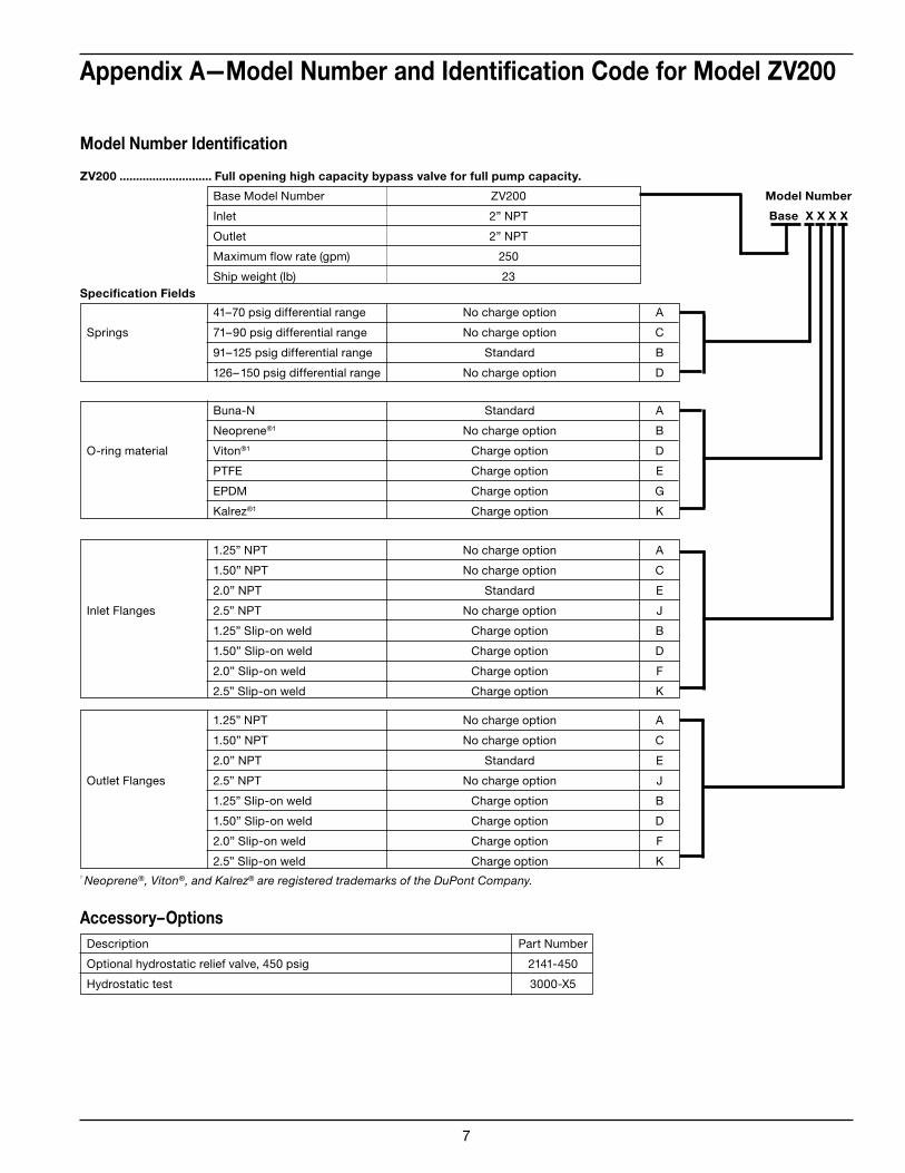
Base Model Number ZV200
Inlet 2” NPT
Outlet 2” NPT
Maximum flow rate (gpm) 250
Ship weight (lb) 23
41–70 psig differential range No charge option A
Springs 71–90 psig differential range No charge option C
91–125 psig differential range Standard B
126–150 psig differential range No charge option D
1.25” NPT No charge option A
1.50” NPT No charge option C
2.0” NPT Standard E
Inlet Flanges 2.5” NPT No charge option J
1.25” Slip-on weld Charge option B
1.50” Slip-on weld Charge option D
2.0” Slip-on weld Charge option F
2.5” Slip-on weld Charge option K
Buna-N Standard A
Neoprene®1 No charge option B
O-ring material Viton®1 Charge option D
PTFE Charge option E
EPDM Charge option G
Kalrez®1 Charge option K
Appendix A—Model Number and Identification Code for Model ZV200
Description Part Number
Optional hydrostatic relief valve, 450 psig 2141-450
Hydrostatic test 3000-X5
Model Number Identification
Model Number
Base X X X X
Accessory–Options
Specification Fields
ZV200 ............................ Full opening high capacity bypass valve for full pump capacity.
1 Neoprene®, Viton®, and Kalrez® are registered trademarks of the DuPont Company.
1.25” NPT No charge option A
1.50” NPT No charge option C
2.0” NPT Standard E
Outlet Flanges 2.5” NPT No charge option J
1.25” Slip-on weld Charge option B
1.50” Slip-on weld Charge option D
2.0” Slip-on weld Charge option F
2.5” Slip-on weld Charge option K
7

Appendix B—Technical Specifications and Performance Curves for the
ZV200 Bypass Valve
Part Material
Adjustment nut cap ASTM A536 65-45-12
Adjusting screw Steel
Bypass valve body Ductile iron: ASTM 536, 60-40-18
Bypass valve cap Ductile iron: ASTM 536, 60-40-18
Gasket 1010 hot rolled steel
FlangesDuctile iron: ASTM 536, 65-45-12 (standard)
Plate steel: ASTM A516 (optional weld)
O-rings Buna-N (standard)
Viton®, Neoprene®, EPDM, PTFE, Kalrez® (optional)2
Spring Music wire/chrome silicon
Spring guide 8620 A322 ASTM steel
Relief valve 17-4 PH stainless steel
Maximum differential pressure: 150 psid (10.34 bar)
Operating temperature range: Up to 225°F (107°C)1
Maximum working pressure: 400 psi (27.6 bar)
Spring ranges: 91–125 psi (6.3–8.6 bar) standard
41–70 psi (2.8–4.8 bar) optional
71–90 psi (4.9–6.2 bar) optional
126–150 psi (9.0–10.3 bar) optional
Performance
2 Viton®, Neoprene®, and Kalrez® are registered trademarks of the DuPont Company.
Material Specifications
Operating Specifications
1 Fitted with Buna-N O-rings.
Differential Pressure
psi (bar)
Maximum Rated Flow for Propane
gpm (L/min)
70 (4.82) 180 (681)
120 (8.27) 250 (946)
8
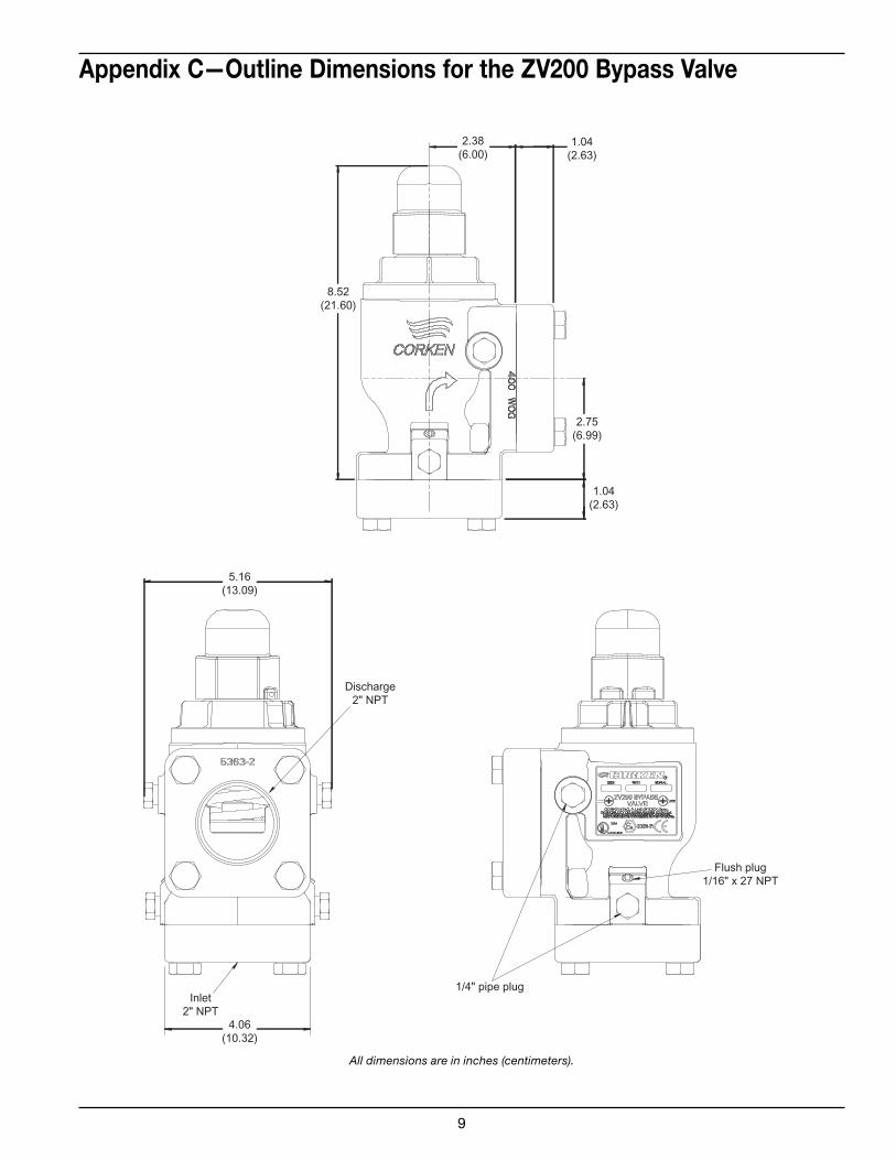
Appendix C—Outline Dimensions for the ZV200 Bypass Valve
8.52(21.60)
2.38(6.00)
2.75(6.99)
1.04(2.63)
1.04(2.63)
5.16(13.09)
4.06(10.32)
Discharge2" NPT
Inlet2" NPT
1/4" pipe plug
Flush plug1/16" x 27 NPT
All dimensions are in inches (centimeters).
9

2
1
3
4
5
7
8
9
10
11
12
13
14
15
16
17183
2
1
6
Appendix D—Parts Details For the ZV200 Bypass Valve
No. Part No. Description Qty
1 7001-050NC175A Hex head bolt 8
5363-1.25 Flange (1.25” NPT) 2
5363-1.5 Flange (1.5” NPT) 2
5363-2 Flange (2” NPT) 2
2 5363-2.5 Flange (2.5” NPT) 2
5363-1.25S Flange (1.25” slip weld) 1
5363-1.5S Flange (1.5” slip weld) 1
5363-2S Flange (2” slip weld) 2
5363-2.5S Flange (2.5” slip weld) 2
3 2-234__ O-ring1 2
4 5506 Bypass valve body 1
5 5509 Relief valve (2”) 1
5511 Valve spring (91–125 psi) 1
6 5512 Valve spring (126–150 psi) 1
5513 Valve spring (41–70 psi) 1
5515 Valve spring (71–90 psi) 1
7 5457 Adjustment nut cap 1
8 7101-037NC01A Hex nut 1
9 2732 Gasket 1
10 2911 Adjusting screw 1
11 5507 Bypass valve cap (2”) 1
12 2-235__ O-ring1 1
13 2-223__ O-ring1 1
14 5516 Spring guide (2”) 1
15 1629 Flush plug 1/16” x 27 NPT 2
16 5510 Nameplate 1
17 7012-006SF019E Pan hd. Phillip 6-32 x 3/16” 2
18 3442 Pipe plug 1/4” NPT 4
1 __ denotes O-ring code. See chart below.
O-ring Code
A Buna-N
B Neoprene®2
D Viton®2
E PTFE
G Ethylene Propylene
K Kalrez®2
2 Registered trademarks of the DuPont company.
10
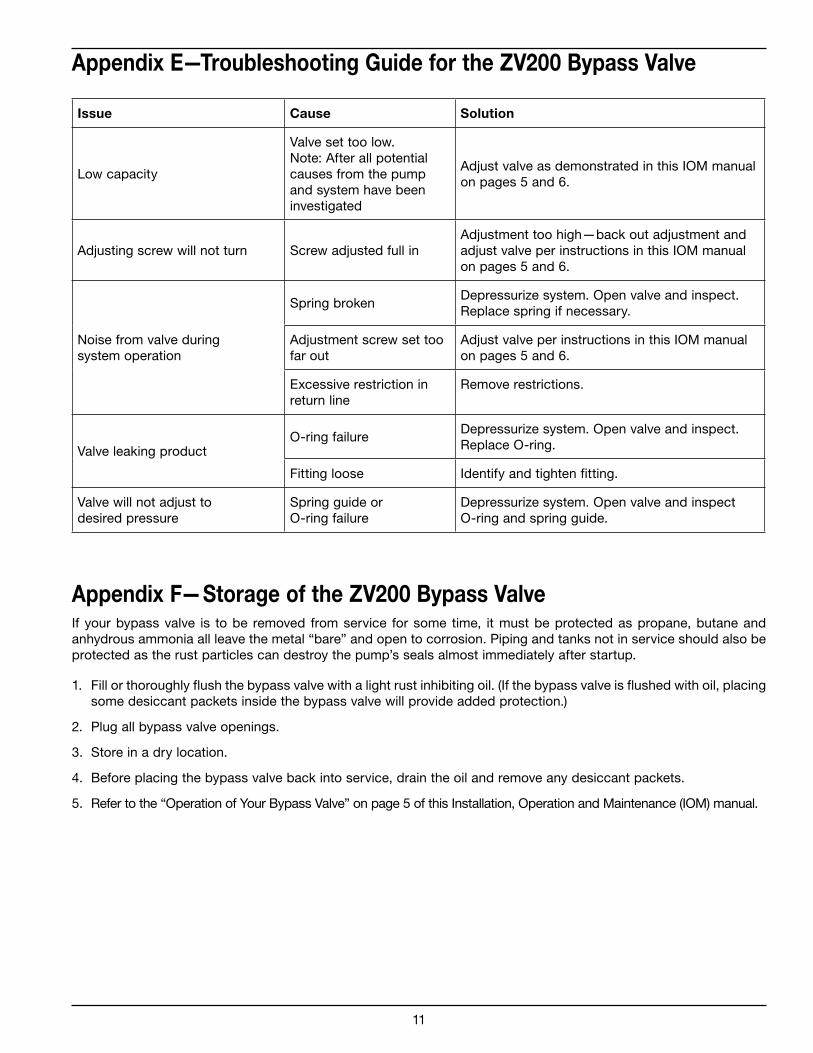
Appendix E—Troubleshooting Guide for the ZV200 Bypass Valve
Issue Cause Solution
Low capacity
Valve set too low.
Note: After all potential
causes from the pump
and system have been
investigated
Adjust valve as demonstrated in this IOM manual
on pages 5 and 6.
Adjusting screw will not turn Screw adjusted full in
Adjustment too high—back out adjustment and
adjust valve per instructions in this IOM manual
on pages 5 and 6.
Noise from valve during
system operation
Spring brokenDepressurize system. Open valve and inspect.
Replace spring if necessary.
Adjustment screw set too
far out
Adjust valve per instructions in this IOM manual
on pages 5 and 6.
Excessive restriction in
return line
Remove restrictions.
Valve leaking productO-ring failure
Depressurize system. Open valve and inspect.
Replace O-ring.
Fitting loose Identify and tighten fitting.
Valve will not adjust to
desired pressure
Spring guide or
O-ring failure
Depressurize system. Open valve and inspect
O-ring and spring guide.
Appendix F—Storage of the ZV200 Bypass ValveIf your bypass valve is to be removed from service for some time, it must be protected as propane, butane and
anhydrous ammonia all leave the metal “bare” and open to corrosion. Piping and tanks not in service should also be
protected as the rust particles can destroy the pump’s seals almost immediately after startup.
1. Fill or thoroughly flush the bypass valve with a light rust inhibiting oil. (If the bypass valve is flushed with oil, placing
some desiccant packets inside the bypass valve will provide added protection.)
2. Plug all bypass valve openings.
3. Store in a dry location.
4. Before placing the bypass valve back into service, drain the oil and remove any desiccant packets.
5. Refer to the “Operation of Your Bypass Valve” on page 5 of this Installation, Operation and Maintenance (IOM) manual.
11
Corken, Inc. • A Unit of IDEX Corporation
3805 N.W. 36th St., Oklahoma City, OK 73112
Phone (405) 946-5576 • Fax (405) 948-7343
Visit our website at http://www.corken.com
or e-mail us at [email protected]
Printed in the U.S.A.
September 2010