Embed Size (px)
Citation preview
1
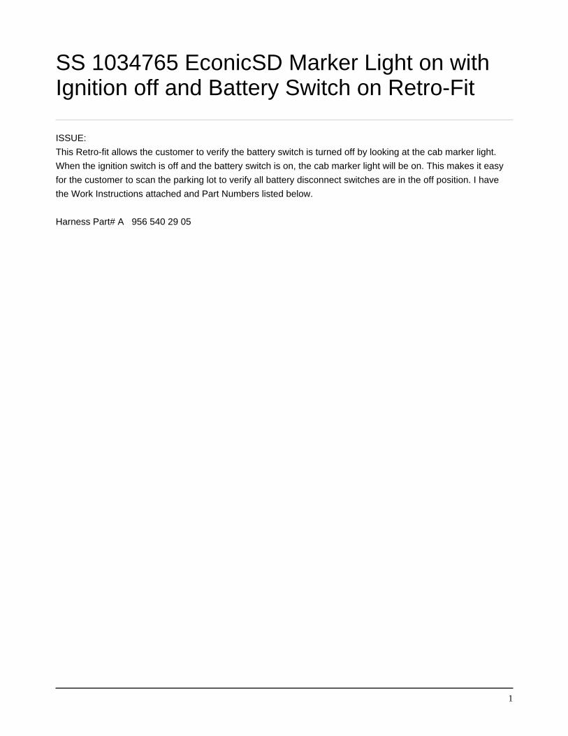
SS 1034765 EconicSD Marker Light on withIgnition off and Battery Switch on Retro-Fit
ISSUE:
This Retro-fit allows the customer to verify the battery switch is turned off by looking at the cab marker light.
When the ignition switch is off and the battery switch is on, the cab marker light will be on. This makes it easy
for the customer to scan the parking lot to verify all battery disconnect switches are in the off position. I have
the Work Instructions attached and Part Numbers listed below.
Harness Part# A 956 540 29 05

Auftr.-Nr./order no.
Manuell00
00
0 0
DIN 7167
A2+1Keine Aenderung ohne Zustimmung der federfuehrenden Konstruktion. / Any alterations are subject to the approval of the design department.
Benennung/title
Oberflaeche/surface (m )
Oberfl.ang./surf.texture
Dekor/decoration
Farbe/color
Oberfl.sch./surf.prot. DBL
Freig./rel.
Norm/stand.
Pruef./check
Bearb./auth.
ZGS
Datum/date Name/name
Blatt/sh.
Norm/stand.Datum/date
Pruef./checkDatum/date
Bearb./auth.Datum/date
Auftrags-Nr.order no.
ZGSAenderungsindex / Aenderungsbeschreibung
state of revision / revision text
Werkstoff(Endzustand)/material(fi.co.)
Format/sz.
Allg.Toleranzen/gen.tolerances gesetzl.Merkmal/st.ftr.
federf.Abt./resp.dep.
Referenz-Nr./reference no.
Massstab/scale
Masse/mass (kg)
System/system
Sach-Nr./basic number
Mercedes-Benz
2
Tolerierung/tolerancing
masterdata
DZ
Stammdaten/
number of features
Anzahl Merkmale/
VeDoc-Relevanz/relevance MBN 10385D-Pflicht/required MBN 10317 ESD-Kennzeichen/code
Art/
type
DS
Anzahl/number of
VPD-Ident-Nr./no.
c Daimler AGSchutzvermerk DIN ISO 16016 beachten! /
Refer to protection notice DIN ISO 16016! IdL A 956 540 29 05
26.11.2019
1 mm : 1 mm
A
B
C
D
E
F
G
H
1 2 3 4 5 6 7 8 9 10 11 12 13 14 15 16
Offenes Leitungsende:
BEL 332 a
BEL 0332 a
Kontakt A 0000 545 37 26 mit anliefern aber
nicht anbringen!
Installation instructions:
Take line BEL 22 a on X1. K2A33 Pin 2 and connect it to the line BEL 332 a
using contact A 0000 545 37 26. Both lines back in the X1. K2A33 Pin 2.
Take line BEL 07 a on X1. K2A33 Pin 4 and connect it to the line BEL 0332 a
using contact A 0000 545 37 26. Both lines back in the X1. K2A33 Pin 4.
40 mm
180 mm
Ltg. BEL 334 a mit offenem
Leitungsende.
Kontakt A0035454326 mit anliefern
aber nicht anbringen!
Offenes Leitungsende:
BEL 333 a
BEL 333 b
Kontakt A 035 545 23 28 mit anliefern
aber nicht anbringen!
Installation instructions:
Remove the line BEL 26 a from connector
X111 PIN 7 and disconnect BEL 26 b. connect
the line BEL 26 a to cable BEL 333 a.
Connect cable BEL 333 b together with BEL 26
b at the contact A 035 545 23 28 and plug in
pin 7 to the X111 connector.
Installation instructions:
Remove the line BEL 242 a on X1. FA3 and
connect together with the line BEL 334 a with
the contact A 003 545 43 26 and pug back in the
X1. FA3 Pin 6.
300 mm
1000 mm

ECONIC SD MARKER LIGHT RETRO-FIT
Step1. Set park brake, chock wheels, and turn off battery disconnect switch.
Step 2. Remove cover for relay and connector panel behind driver seat.
Step 3. Install relay connector in relay panel location X1.K6A33. (Figure 1)
Step 4. Install circuit BEL 22 a and BEL 332 a using terminal A 0000 545 37 26
In connector X1.K2A33 pin 2 in relay panel.
Step 5. Install circuit BEL 07 a and circuit BEL 0332 a using terminal A0000 545 37 26
in connector X1.K2A33 pin 4 relay panel.
Step 6. Install circuit BEL 242 a and BEL 334 a using terminal A 003 545 43 26 in
connector X1.FA3 pin 6 in fuse panel.(Figure 2)
Step 7. Remove circuit BEL 26 a from connector X111 pin 7 and connect circuit 333 a
Using terminal A 035 545 23 28. (Figure 3)
Step 8. Connect circuit BEL 333 b and BEL 26 b with terminal A 035 545 23 28 and install
in connector X111 pin 7.
Step 9. Reverse Steps 3-1.
Figure 1

Figure 2
Figure 3