Embed Size (px)
Citation preview

7/24/2019 IFR6000 Brochure
http://slidepdf.com/reader/full/ifr6000-brochure 1/12
For the very latest specifications visit www.aeroflex.com
The IFR 6000 is a compact, light weight and weatherproof unit designed for testing transponder
modes A/C/S, TCAS I and II as well as DME.
Avionics
IFR 6000 Ramp Test Set
• One main user screen for each test mode
• Detachable antenna
• Large display
• Simple user interface
• Lightweight and compact <8 lbs. (3.6 kg)
• Battery 6 hours plus duration
• Fully FAR part 43 appendix F compliant
• European Elementary and Enhanced
Surveillance
The IFR6000 features an extremely easy to use
interface where every parameter the user com-
monly needs to view is displayed on screen.
Controls
Dedicated Mode keys for XPDR, DME and TCAS
allow quick selection of the operational mode.
The application dependant softkeys and data
select/slew keys provide an intuitive man machine
interface.
DME mode is provided with dedicated keys for
frequency/channel selection and RF level control.
For frequently varied parameters in DME and
TCAS modes, such as Range and Rate, dedicated
keys are provided.
Operational ModesEach operational mode has one main user screen. The operational
modes are:
XPDR (Sub-Modes: ADS-B MON, ADS-B GEN & GICB)
DME
TCAS 1, 2 (Sub-Modes: TIS)
Most tests can be completed without leaving the main user screens.
This simplifies the line technician's testing task.
7/24/2019 IFR6000 Brochure
http://slidepdf.com/reader/full/ifr6000-brochure 2/12
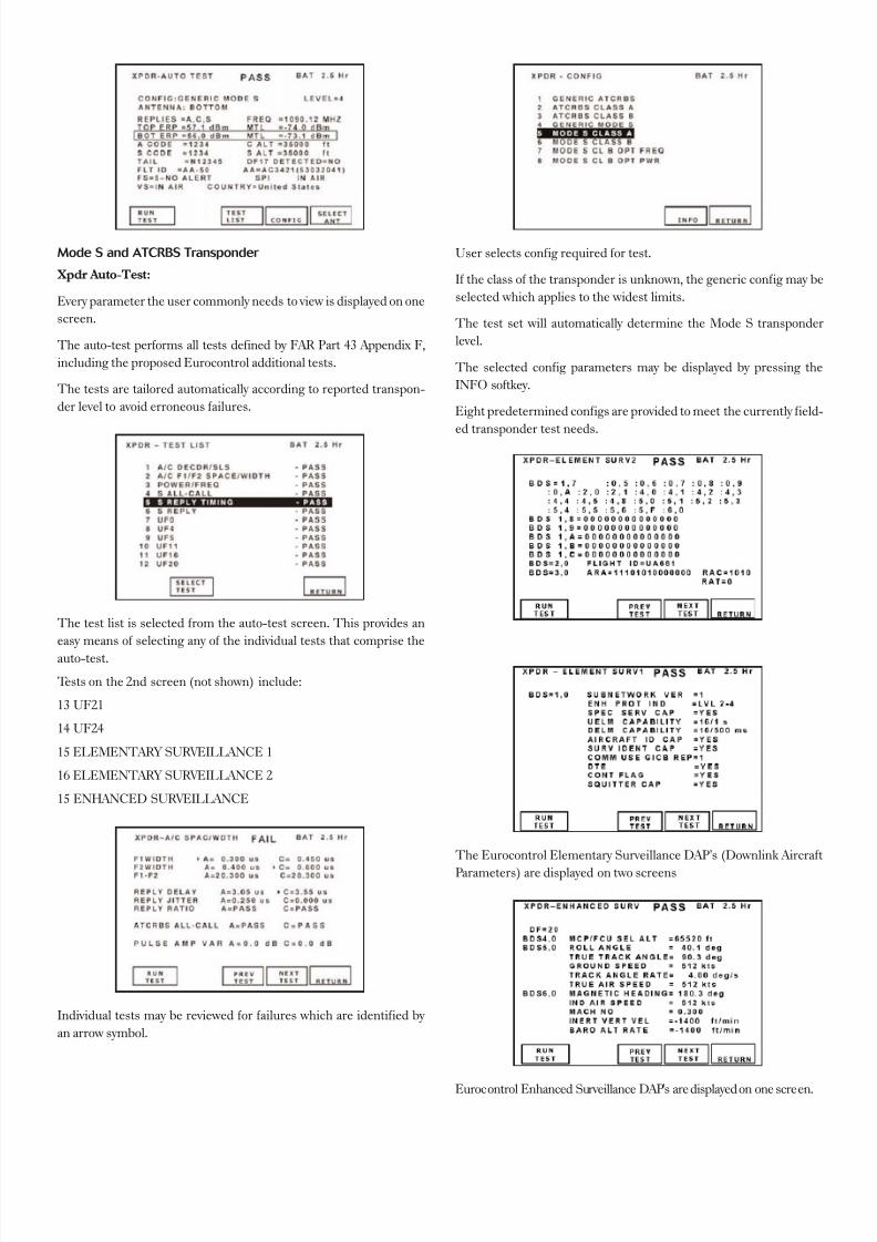
Mode S and ATCRBS Transponder
Xpdr Auto-Test:
Every parameter the user commonly needs to view is displayed on one
screen.
The auto-test performs all tests defined by FAR Part 43 Appendix F,
including the proposed Eurocontrol additional tests.
The tests are tailored automatically according to reported transpon-
der level to avoid erroneous failures.
The test list is selected from the auto-test screen. This provides an
easy means of selecting any of the individual tests that comprise the
auto-test.
Tests on the 2nd screen (not shown) include:
13 UF21
14 UF24
15 ELEMENTARY SURVEILLANCE 1
16 ELEMENTARY SURVEILLANCE 2
15 ENHANCED SURVEILLANCE
Individual tests may be reviewed for failures which are identified by
an arrow symbol.
User selects config required for test.
If the class of the transponder is unknown, the generic config may be
selected which applies to the widest limits.
The test set will automatically determine the Mode S transponder
level.
The selected config parameters may be displayed by pressing the
INFO softkey.
Eight predetermined configs are provided to meet the currently field-
ed transponder test needs.
The Eurocontrol Elementary Surveillance DAP's (Downlink Aircraft
Parameters) are displayed on two screens
Eurocontrol Enhanced Surveillance DAP's are displayed on one screen.
7/24/2019 IFR6000 Brochure
http://slidepdf.com/reader/full/ifr6000-brochure 3/12
For the very latest specifications visit www.aeroflex.com
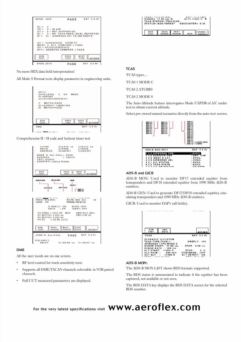
No more HEX data field interpretation!
All Mode S Format tests display parameter in engineering units.
Comprehensive II / SI code and lockout timer test
DME
All the user needs are on one screen.
• RF level control for track sensitivity tests
• Supports all DME/TACAN channels selectable in VOR pairedchannels
• Full UUT measured parameters are displayed.
TCAS
TCAS types…
TCAS 1 MODE C
TCAS 2 ATCRBS
TCAS 2 MODE S
The Auto-Altitude feature interrogates Mode S XPDR of A/C undertest to obtain current altitude.
Select pre-stored named scenarios directly from the auto-test screen.
ADS-B and GICB
ADS-B MON: Used to monitor DF17 extended squitter fromtransponders and DF18 extended squitter from 1090 MHz ADS-Bemitters.
ADS-B GEN: Used to generate DF17/DF18 extended squitter, sim-ulating transponders and 1090 MHz ADS-B emitters.
GICB: Used to monitor DAP's (all fields).
ADS-B MON:
The ADS-B MON LIST shows BDS formats supported.
The BDS status is annunciated to indicate if the squitter has beencaptured, not available or not seen.
The BDS DATA key displays the BDS DATA screen for the selectedBDS number.
7/24/2019 IFR6000 Brochure
http://slidepdf.com/reader/full/ifr6000-brochure 4/12
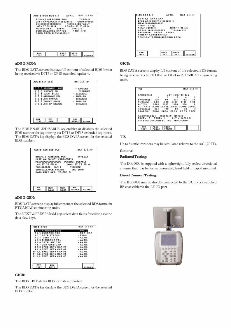
ADS-B MON:
The BDS DATA screen displays full content of selected BDS formatbeing received via DF17 or DF18 extended squitters.
The BDS ENABLE/DISABLE key enables or disables the selectedBDS number for squittering via DF17 or DF18 extended squitters.The BDS DATA key displays the BDS DATA screen for the selectedBDS number.
ADS-B GEN:
BDS DATA screens display full content of the selected BDS format inRTCA/ICAO engineering units.
The NEXT & PREV PARAM keys select data fields for editing via thedata slew keys.
GICB:
The BDS LIST shows BDS formats supported.
The BDS DATA key displays the BDS DATA screen for the selectedBDS number.
GICB:
BDS DATA screens display full content of the selected BDS format
being received via GICB DF20 or DF21 in RTCA/ICAO engineering
units.
TIS
Up to 5 static intruders may be simulated relative to the A/C (UUT).
General
Radiated Testing:
The IFR 6000 is supplied with a lightweight fully sealed directional
antenna that may be test set mounted, hand held or tripod mounted.
Direct Connect Testing:
The IFR 6000 may be directly connected to the UUT via a supplied
RF coax cable via the RF I/O port.

7/24/2019 IFR6000 Brochure
http://slidepdf.com/reader/full/ifr6000-brochure 5/12
For the very latest specifications visit www.aeroflex.com
Transit Case:
The IFR-6000 is supplied in a rugged plastic transit case which pro-
vides stowage for the test set, directional antenna, RF coax cable,
antenna shield, breakout box, and power supply/charger.
SPECIFIC ATION
DME MODE S PEC IF ICAT IONS
SIGNAL GENER AT OR
A 5-minute warm-up period is required for all specifications.
OUT PU T F RE QU ENCY
REPLY FREQUENCY
Range
962 to 1213 MHz
Accuracy
± 10 kHzOUT PU T LEVEL
ANTENNA PORT
Range
-67 to -2 dBm at Antenna port
Resolution
1 dB
Accuracy
± 2 dB
Distance to UUT antenna
6 to 300 ft with supplied antenna
RF I/O PORT
Range
-115 to -47 dBm
Resolution
1 dB
Accuracy
-95 dBm to –47 dBm ± 1 dB
Accuracy
-115 dBm to <-95 dBm ± 2 dB
REP LY P UL SE SPAC ING
P1 to P2
12 µ s ± 100 ns (X Channel) @ 50% peak
P1 to P2
30 µ s ± 100 ns (Y Channel) @ 50% peak
REP LY P UL S E W IDT H
P1/P2
3.5 µ s ± 0.5 µ s
EC HO REPLY
Control
On/Off
Position
30 nmi ± 1 nmi
Amplitude
-11 dB ± 1 dB relative to reply level
REP LY P UL SE RISE AND FALL T IMES
ALL PULSES
Rise Time
2.5 µ s ± 0.25 µ s (10% to 90%)Fall Time
2.5 µ s ± 0.25 µ s (90% to 10%)
REP LY DEL AY
X CHANNEL
Fixed Reply Delay
50 µ s ± 100 ns
Y CHANNEL
Fixed Reply Delay
56 µ s ± 100 ns
R ANGE DE L AY
X AND Y CHANNEL
Range
0 to 450.00 nmi
Resolution
0.01 nmi
Accuracy
± 0.01 nmi
R ANGE R AT E
X AND Y CHANNEL
Range
10 to 6500 kts
Resolution
1 kts Accuracy
± 0.01% typical, tested to ± 0.5%
SQUI T T ER
PRF
2700 Hz
Accuracy
± 2%
Distribution
Per ARINC 568
7/24/2019 IFR6000 Brochure
http://slidepdf.com/reader/full/ifr6000-brochure 6/12
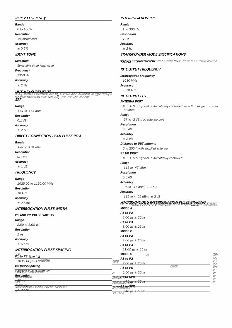
REPLY EFF IC IENCY
Range
0 to 100%
Resolution
1% increments
Accuracy
± 0.5%
IDENT T ONE
Selection
Selectable three letter code
Frequency
1350 Hz
Accuracy
± 2 Hz
UU T ME ASUREME NT S
ERP
Range
+47 to +64 dBm
Resolution
0.1 dB
Accuracy
± 2 dB
DIRECT CONNECT ION PE AK PULSE P OW ER
Range
+47 to +64 dBm
Resolution
0.1 dB
Accuracy
± 1 dB
FREQUENCY
Range
1025.00 to 1150.00 MHz
Resolution
10 kHz
Accuracy
± 20 kHz
INTERROGATION PULSE WIDTH
P1 AND P2 PULSE WIDTHS
Range
2.00 to 5.00 µ s
Resolution1 ns
Accuracy
± 50 ns
INTERROG AT ION PULSE SPACING
P1 to P2 Spacing
10 to 14 µ s (X Channel)
P1 to P2 Spacing
34 to 38 µ s (Y Channel)
Resolution
10 ns
Accuracy
± 20 ns
INTERROG AT ION PRF
Range
1 to 300 Hz
Resolution
1 Hz
Accuracy
± 2 Hz
T R ANS PONDER MODE SPECI F IC AT I ONS
S IGN AL GENE R ATOR
RF OUTP UT F REQUE NCY
Interrogation Frequency
1030 MHz
Accuracy
± 10 kHz
RF OUT P UT LEV EL
ANTENNA PORT
MTL + 6 dB typical, automatically controlled for a MTL range of -83 to
-68 dBm
Range-67 to -2 dBm at antenna port
Resolution
0.5 dB
Accuracy
± 2 dB
Distance to UUT antenna
6 to 200 ft with supplied antenna
RF I/O PORT
MTL + 6 dB typical, automatically controlled
Range
-115 to -47 dBm
Resolution
0.5 dB
Accuracy
-95 to –47 dBm, ± 1 dB
Accuracy
-115 to <-95 dBm, ± 2 dB
AT CRBS /MODE S INT E RROG ATION PULSE S PAC ING
MODE A
P1 to P2
2.00 µ s ± 25 ns
P1 to P3
8.00 µ s ± 25 ns
MODE C
P1 to P2
2.00 µ s ± 25 ns
P1 to P3
21.00 µ s ± 25 ns
MODE S
P1 to P2
2.00 µ s ± 25 ns
P1 to P6
3.50 µ s ± 25 ns
P1 to SPR
4.75 µ s ± 25 ns
P5 to SPR0.40 µ s ± 50 ns
7/24/2019 IFR6000 Brochure
http://slidepdf.com/reader/full/ifr6000-brochure 7/12
For the very latest specifications visit www.aeroflex.com
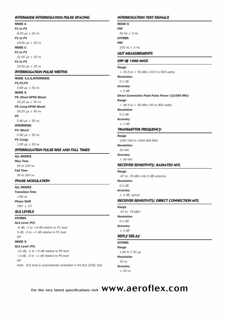
IN T ERMODE I NT ERROGATION PULSE SPACING
MODE A
P1 to P3
8.00 µ s ± 25 ns
P1 to P4
10.00 µ s ± 25 ns
MODE C
P1 to P3
21.00 µ s ± 25 ns
P1 to P4
23.00 µ s ± 25 ns
IN TERROG ATION P ULS E WIDT HS
MODE A,C,S,INTERMODE
P1,P2,P3
0.80 µ s ± 50 ns
MODE S
P6 (Short DPSK Block)
16.25 µ s ± 50 ns
P6 (Long DPSK Block)
30.25 µ s ± 50 nsP5
0.80 µ s ± 50 ns
INTERMODE
P4 (Short)
0.80 µ s ± 50 ns
P4 (Long)
1.60 µ s ± 50 ns
IN T ERROG AT I ON P ULS E RISE AND FALL T IMES
ALL MODES
Rise Time
50 to 100 ns
Fall Time
50 to 200 ns
PHASE MODULAT ION
ALL MODES
Transition Time
≤ 80 ns
Phase Shift
180° ± 10°
SLS LEVELS
ATCRBS
SLS Level (P2)
-9 dB, -1 to +0 dB relative to P1 level
0 dB, -0 to +1 dB relative to P1 level
Off
MODE S
SLS Level (P5)
-12 dB, -1 to +0 dB relative to P6 level
+3 dB, -0 to +1 dB relative to P6 level
Off
Note: SLS level is automatically controlled in the SLS LEVEL test.
IN T ERROG AT I ON T EST SIGN AL S
MODE S
PRF
50 Hz ± 5 Hz
ATCRBS
PRF
235 Hz ± 5 Hz
UUT ME AS UREMEN TS
ERP (@ 1090 MH Z )
Range
+ 45.5 to + 59 dBm (35.5 to 800 watts)
Resolution
0.1 dB
Accuracy
± 2 dB
Direct Connection Peak Pulse Power (@1090 MHz)
Range
+ 46.5 to + 59 dBm (45 to 800 watts)
Resolution
0.1 dB
Accuracy
± 1 dB
TRANSMIT TER FREQUENCY
Range
1087.000 to 1093.000 MHz
Resolution
10 kHz
Accuracy
± 50 kHz
RECEIVER SE NSIT IVI T Y, RADI AT ED MT L
Range
-67 to -79 dBm into 0 dBi antenna
Resolution
0.1 dB
Accuracy
± 2 dB, typical
RECEIVER SE NSITIVI T Y, DIR ECT CONNECTION MTL
Range
-67 to -79 dBm
Resolution
0.1 dB
Accuracy
± 2 dB
REP LY DEL AY
ATCRBS
Range
1.80 to 7.00 µ s
Resolution
10 ns
Accuracy
± 50 ns
7/24/2019 IFR6000 Brochure
http://slidepdf.com/reader/full/ifr6000-brochure 8/12
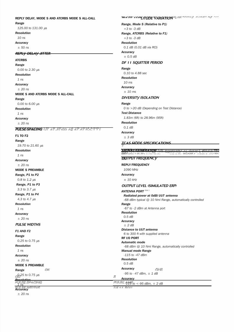
REPLY DELAY, MODE S AND ATCRBS MODE S ALL-CALL
Range
125.00 to 131.00 µ s
Resolution
10 ns
Accuracy
± 50 ns
REPLY DEL AY JIT T ER
ATCRBS
Range
0.00 to 2.30 µ s
Resolution
1 ns
Accuracy
± 20 ns
MODE S AND ATCRBS MODE S ALL-CALL
Range
0.00 to 6.00 µ s
Resolution
1 ns
Accuracy
± 20 ns
PULSE SPACING
F1 TO F2
Range
19.70 to 21.60 µ s
Resolution
1 ns
Accuracy
± 20 ns
MODE S PREAMBLE
Range, P1 to P2
0.8 to 1.2 µ s
Range, P1 to P3
3.3 to 3.7 µ s
Range, P1 to P4
4.3 to 4.7 µ s
Resolution
1 ns
Accuracy
± 20 ns
PULSE WIDTHS
F1 AND F2
Range
0.25 to 0.75 µ s
Resolution
1 ns
Accuracy
± 20 ns
MODE S PREAMBLE
Range
0.25 to 0.75 µ s
Resolution
1 ns
Accuracy ± 20 ns
PULSE AMP LIT UDE VARI ATION
Range, Mode S (Relative to P1)
+3 to -3 dB
Range, ATCRBS (Relative to F1)
+3 to -3 dB
Resolution
0.1 dB (0.01 dB via RCI)
Accuracy
± 0.5 dBDF 11 SQU ITT ER PERI OD
Range
0.10 to 4.88 sec
Resolution
10 ms
Accuracy
± 10 ms
DIV ERSITY ISOL AT ION
Range
0 to >20 dB (Depending on Test Distance)
Test Distance
1.83m (6ft) to 28.96m (95ft)
Resolution
0.1 dB
Accuracy
± 3 dB
T C AS MODE SPECIF IC AT I ONS
S IGN AL GENE RAT OR
OU TPUT FR EQUENCY
REPLY FREQUENCY
1090 MHz
Accuracy
± 10 kHz
OU T PUT LEVE L (SIMUL AT ED ERP)
ANTENNA PORTNote 1
Radiated power at 0dBi UUT antenna
-68 dBm typical @ 10 Nmi Range, automatically controlled
Range
-67 to -2 dBm at Antenna port
Resolution
0.5 dB
Accuracy
± 2 dB
Distance to UUT antenna
6 to 300 ft with supplied antenna
RF I/O PORT
Automatic mode
-68 dBm @ 10 Nmi Range, automatically controlled
Manual mode Range
-115 to -47 dBm
Resolution
0.5 dB
Accuracy
-95 to –47 dBm, ± 1 dB
Accuracy
-115 to <-95 dBm, ± 2 dB
7/24/2019 IFR6000 Brochure
http://slidepdf.com/reader/full/ifr6000-brochure 9/12
For the very latest specifications visit www.aeroflex.com
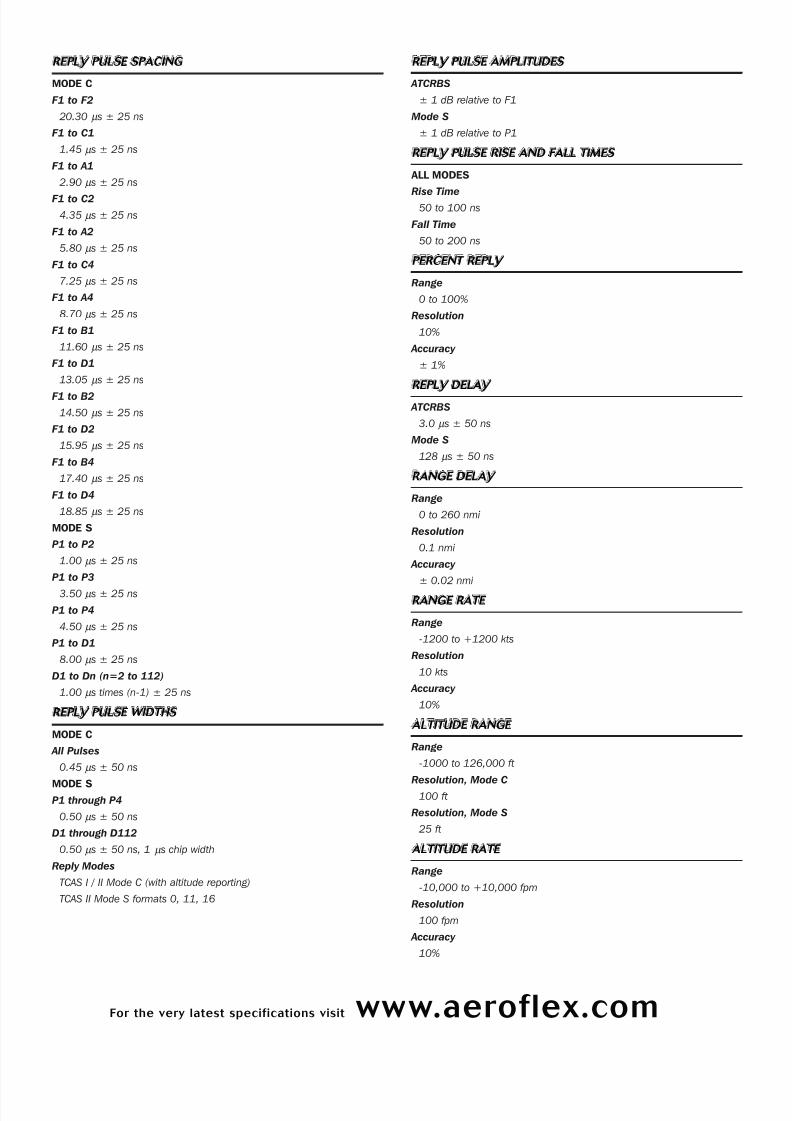
REP LY P ULS E SPAC ING
MODE C
F1 to F2
20.30 µ s ± 25 ns
F1 to C1
1.45 µ s ± 25 ns
F1 to A1
2.90 µ s ± 25 ns
F1 to C2
4.35 µ s ± 25 ns
F1 to A2
5.80 µ s ± 25 ns
F1 to C4
7.25 µ s ± 25 ns
F1 to A4
8.70 µ s ± 25 ns
F1 to B1
11.60 µ s ± 25 ns
F1 to D1
13.05 µ s ± 25 ns
F1 to B2
14.50 µ s ± 25 ns
F1 to D2
15.95 µ s ± 25 ns
F1 to B4
17.40 µ s ± 25 ns
F1 to D4
18.85 µ s ± 25 ns
MODE S
P1 to P2
1.00 µ s ± 25 ns
P1 to P3
3.50 µ s ± 25 ns
P1 to P4
4.50 µ s ± 25 ns
P1 to D1
8.00 µ s ± 25 ns
D1 to Dn (n=2 to 112)
1.00 µ s times (n-1) ± 25 ns
REP LY P ULS E WIDT HS
MODE C
All Pulses
0.45 µ s ± 50 ns
MODE SP1 through P4
0.50 µ s ± 50 ns
D1 through D112
0.50 µ s ± 50 ns, 1 µ s chip width
Reply Modes
TCAS I / II Mode C (with altitude reporting)
TCAS II Mode S formats 0, 11, 16
REP LY P UL SE AMP L ITUDES
ATCRBS
± 1 dB relative to F1
Mode S
± 1 dB relative to P1
REP LY P UL SE RISE AND FALL T IMES
ALL MODES
Rise Time50 to 100 ns
Fall Time
50 to 200 ns
P ERCENT REP LY
Range
0 to 100%
Resolution
10%
Accuracy
± 1%
REP LY DEL AY
ATCRBS
3.0 µ s ± 50 ns
Mode S
128 µ s ± 50 ns
R ANGE DE L AY
Range
0 to 260 nmi
Resolution
0.1 nmi
Accuracy
± 0.02 nmi
R ANGE R ATE
Range
-1200 to +1200 kts
Resolution
10 kts
Accuracy
10%
ALT IT UDE R ANG E
Range
-1000 to 126,000 ft
Resolution, Mode C
100 ft
Resolution, Mode S
25 ft
ALT IT UDE R AT E
Range
-10,000 to +10,000 fpm
Resolution
100 fpm
Accuracy
10%

7/24/2019 IFR6000 Brochure
http://slidepdf.com/reader/full/ifr6000-brochure 10/12
SQUIT TER
Control
On/Off
Rate
0.8 to 1.2 seconds, randomly distributed
REC EIVER
PULSE SPACING
ATCRBS (Mode C All Call) S1 to P1 2.0 us
Accepts ≤ ±200 ns
Rejects ≥ ±1.0 us
P1 to P3 21.0 us
Accepts ≤ ±200 ns
Rejects (<10% Replies) ≥ ±1.0 us
P1 to P4 23.0 us
Accepts ≤ ±200 ns
Rejects (<10% Replies) ≥ ±1.0 us
Mode S
P1 to P2 2.0 us
Accepts ≤ ±200 nsRejects (<10% Replies) ≥ ±1.0 us
P1 to SPR 4.75 us
Accepts ≤ ±200 ns
Rejects (<10% Replies) ≥ ±1.5 us
SUP P RES ION
ATCRBS (P2 or S1)
>0.5dB above level of P1 <10% Replies
UU T ME ASUREME NT S
ERP (@1030MHZ)
ATCRBS
Range
+43 to +58 dBm (20 to 631 watts)
Resolution
0.1 dB
Accuracy
± 2 dB
MODE S
Range
+43 to +58 dBm (20 to 631 watts)
Resolution
0.1 dB
Accuracy
± 2 dB
DIRECT CONNECTION PE AK PULS E P OW ER (@1030MHZ )
ATCRBS
Range
+43 to +58 dBm (20 to 631 watts)
Resolution
0.1 dB
Accuracy
± 1 dB
MODE S
Range
+43 to +58 dBm (20 to 631 watts)
Resolution
0.1 dB
Accuracy
± 1 dB
F REQ UENCY
Range
1029.900 to 1030.100 MHz
Resolution
1 kHz
Accuracy
± 10 kHz
TCAS BROADCAST INTERVAL
Range
1.0 to 12.0 sec
Resolution
0.1 sec
Accuracy ± 0.2 sec
MISCELL ANEOUS INPUT/OUT P UT S
RF I/O
Type
Input/Output
Impedance
50 Ω typical
Maximum Input Level
4 kW peak
10 W average
VSWR
< 1.3:1
ANTENNA
Type
Input/Output
Impedance
50 Ω typical
Maximum Input Level
10 W peak
1/2 W average
VIDEO
Type
Output
Impedance
50 Ω typical
Generate Video Level
1.1 ± 0.4V peak to peak into 50 Ω
Receive Video Level
Proportional to IF level
Baseline
± 0.5V referenced to ground
7/24/2019 IFR6000 Brochure
http://slidepdf.com/reader/full/ifr6000-brochure 11/12
For the very latest specifications visit www.aeroflex.com
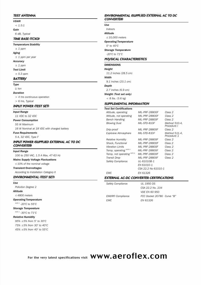
T EST ANT ENN A
VSWR
< 1.5:1
Gain
6 dB, Typical
TIME BASE ( TCXO)
Temperature Stability
± 1 ppm Aging
± 1 ppm per year
Accuracy
± 1 ppm
Test Limit
± 0.3 ppm
BAT TERY
Type
Li Ion
Duration
> 4 hrs continuous operation
> 6 hrs, Typical
INP UT P OW ER ( T EST S E T)
Input Range
11 VDC to 32 VDC
Power Consumption
55 W Maximum
16 W Nominal at 18 VDC with charged battery
Fuse Requirements
5 A, 32 VDC, Type F
INP UT P OWER (SUP P L IED E X T ERNAL AC TO DC
CONVERT E R )
Input Range
100 to 250 VAC, 1.5 A Max, 47-63 Hz
Mains Supply Voltage Fluctuations
≤ 10% of the nominal voltage
Transient Overvoltages
According to Installation Category II
ENVIRONMENTAL ( T EST S ET)
Use
Pollution Degree 2
Altitude
≤ 4800 meters
Operating TemperatureNOTE 3
-20°C to 55°C
Storage Temperature
NOTE 4-30°C to 71°C
Relative Humidity
95% ±5% from 5° to 30°C
75% ±5% from 30° to 40°C
45% ±5% from 40° to 55°C
ENVIRONMENTAL (SUP P LIED E X T ERNAL AC T O DC
CONV ERT E R )
Use
Indoors
Altitude
≤ 10,000 meters
Operating Temperature
0° to 40°C
Storage Temperature
-20°C to 71°C
P HY SIC AL C H AR ACT ERIST ICS
DIMENSIONS
Height
11.2 inches (28.5 cm)
Width
9.1 inches (23.1 cm)
Depth
2.7 inches (6.9 cm)
Weight (Test set only)
< 8 lbs. (3.6 kg)
SUP PLEMENTAL I NF ORMAT ION
Test Set Certifications
Altitude, operating MIL-PRF-28800F Class 2
Altitude, not operating MIL-PRF-28800F Class 2
Bench Handling MIL-PRF-28800F Class 2
Blowing Dust MIL-STD-810F Method 510.4,Procedure I
Drip-proof MIL-PRF-28800F Class 2
Explosive Atmosphere MIL-STD-810F Method 511.4,Procedure 1
Relative Humidity MIL-PRF-28800F Class 2
Shock, Functional MIL-PRF-28800F Class 2
Vibration Limits MIL-PRF-28800F Class 2
Temp, operating NOTE 5 MIL-PRF-28800F Class 2
Temp, not operatingNOTE 6
MIL-PRF-28800F Class 2
Transit Drop MIL-PRF-28800F Class 2
Safety Compliance UL-61010B-1
EN 61010-1
CSA 22.2 No 61010-1
EMC EN 61326
E X TERN AL AC-DC CONVERTE R CE RTIFICAT IONS
Safety Compliance UL 1950 DS
CSA 22.2 No. 234
VDE EN 60 950
EMI/RFI Compliance FCC Docket 20780 Curve “B”
EMC EN 61326
7/24/2019 IFR6000 Brochure
http://slidepdf.com/reader/full/ifr6000-brochure 12/12
Part No. 46891/184, Issue 7, 03/06
CHINA Beijing
Tel: [+86] (10) 6539 1166
Fax: [+86] (10) 6539 1778
CHINA Shanghai
Tel: [+86] (21) 5109 5128
Fax: [+86] (21) 5150 6112
FINLAND
Tel: [+358] (9) 2709 5541
Fax: [+358] (9) 804 2441
FRANCE
Tel: [+33] 160 79 96 00
Fax: [+33] 1 60 7769 22
GERMANY
Tel: [+49] 81312926-0
Fax: [+49] 81312926-130
HONG KONG
Tel: [+852] 2832 7988
Fax: [+852] 2834 5364
INDIA
Tel: [+91] 80 5115 4501
Fax: [+91] 80 5115 4502
KOREA
Tel: [+82] (2) 3424 2719
Fax: [+82] (2) 3424 8620
SCANDINAVIA
Tel: [+45] 9614 0045
Fax: [+45] 9614 0047
SPAIN
Tel: [+34] (91) 640 11 34
Fax: [+34] (91) 640 06 40
UK Burnham
Tel: [+44] (0) 1628 604455
Fax: [+44] (0) 1628 662017
UK Cambridge
Tel: [+44] (0) 1763 262277
Fax: [+44] (0) 1763 285353
UK Stevenage
Tel: [+44] (0) 1438 742200
Fax: [+44] (0) 1438 727601
Freephone: 0800 282388
USA
Tel: [+1] (316) 5224981
Fax: [+1] (316) 522 1360
Toll Free: 800 835 2352
w w w . a e r o f l e x . c o m
i n f o - t e s t @ a e r o f l e x . c o m
As we are always seeking to improve our products,
the information in this document gives only a general
indication of the product capacity, performance and
suitability, none of which shall form part of any con-
tract. We reserve the right to make design changes
without notice. All trademarks are acknowledged.
Parent company Aeroflex, Inc. ©Aeroflex 2006.
Our passion for performance is defined by three
attributes represented by these three icons:
solution-minded, performance-driven and customer-focused.
T R ANSI T CAS E CE RT IF IC AT IONS
Drop Test FED-STD-101C Method 5007.1
Paragraph 6.3,
Procedure A,
Level A
Falling Dart Impact ATA 300 Category I
Vibration, Loose Cargo FED-STD-101C Method 5019
Vibration, Sweep ATA 300 Category I
Simulated Rainfall MIL-STD-810F Method 506.4
Procedure II of 4.1.2
FED-STD-101C Method 5009.1
Sec 6.7.1
Immersion MIL-STD-810F Method 512.4
NotesNOTE 1
Simulates a 50.5 dBm XPDR ERP at 10 nMi range.NOTE 2
Level automatically controlled based on actual distance to UUT antenna.NOTE 3
Battery charging temperature range: 5°C to 40°C (controlled by internalcharger).
NOTE 4Li Ion Battery must be removed below -20°C and above 60°C.
NOTE 5 Temperature range extended to -20°C to 55°C.
NOTE 6 Temperature range reduced to -30°C to 71°C.
VERSIONS AND ACCESSORIES
When ordering please quote the full ordering number information.
Ordering
Numbers Versions
6000-110 IFR 6000 Mode A/C/S Transponder and DMERamp Test Set, with US Mains Leads
6000-220 IFR 6000 Mode A/C/S Transponder and DMERamp Test Set, with European Mains Leads
6000OPT2 TCAS (TIS)
6000OPT3 ADS-B
Extended Standard Warranties with Calibration for 6000
W6000/203C Extended standard warranty 36 months withscheduled calibration
W6000/205C Extended standard warranty 60 months withscheduled calibration
Accessories for 6000
AC0820 Desk Top Stand
AC0826 Tripod
AC0825CD IFR 6000 Operation Manual - CD
AC24006 Tripod, Dolly, Stand


![Ac Brochure 2009 Brochure]](https://img.dokumen.tips/doc/110x75/577d2f551a28ab4e1eb16a35/ac-brochure-2009-brochure.jpg)

