Embed Size (px)
Citation preview
Ener^v ^’i^es ?-na
Resources Canaaa
CANMETCanada Centretor Mineraland EnergyTechnology
Energio. Mines eTRessources Canaaa
Centre canadiende ta technofogiedes mineraux
et de lenergie �
EMANATION OF RADON FROM SOLID SAMPLES
J. BIGU, E.D. HALLMAN AND L. KENDRICK
ELLIOT LAKE LABORATORY
NOVEMBER 1991
Sudbury Neutrino Observatory Project Report SNO-STR-91-068
MINING RESEARCH LABORATORYDIVISION REPORT 91- (TR)
EMANATION OF RADON FROM SOLID SAMPLES
J. Bigu*, E.D. Hallman** and L. Kendrick***
ABSTRACT
This report presents a brief review as well as some
theoretical background on radon (^Rn) emanation methods from solid samples.
This is followed by a description of an experimental apparatus built at the
Elliot Lake Laboratory. (Mining Research Laboratory. CANMET, E.M.R.) to measure
the ^Rn emanation rate from ^Ra-bearing solid materials by the vacuum
emanation method. Experimental data are presented on three materials, namely,
Viton� ’O’-ring. coaxial cable Belden M9067, and a molecular sieve (zeolite).
The results of this study and other investigations presently in progress are
relevant to the Sudbury Neutrino Observatory (SNO) Project.
Key words: Radon emanation; Pathways; Measurement techniques.
*Research Scientist (Mining Research Laboratory. CANMET, Energy, Mines and
Resources Canada) and Adjunct Professor (Laurentian University); **Professor,
(Laurentian university); ***Research Technologist (Laurentian University).
INTRODUCTION
Uranium-238,’ ^Th. and 235^ are the parents of three
naturally occurring radioactive decay chains which are more or less uniformly
distributed on the crust of the earth. Through a series of radioactive decays
238^ 232^ ^ 235y ^^ respectively, ^Ra, ^Ra, and ^Ra. These
222metal radionuclides decay, respectively, into the radioactive gases Rn
(radon), ^Rn (thoron) . and ^Rn (actinon). which readily diffuse through
rt �} (-
solids and dissolve in liquids. Because "-U only represents a small fraction
me
(-0.7%) of the natural U content, the contribution of ---U to the natural
radioactivity environment is often neglected in most practical applications.
The natural abundance of 23S^ and ^^h varies with
99Ageographical location, depth, and other factors. THe abundance of Ra and
^^Ra depends on meteorological and geological factors, as well as with the
chemistry and physical characteristics of the soil environment. These and
other variables and factors, partly determine (through selective leaching
processes, a-recoil mechanisms and transport phenomena) radionuclide
disequilibrium ratios in the radioactive decay chains.
The ^Ra and ^Ra content in a given material or chemical
compound may be of ’natural’ origin, or the result of a physico-chemical
reaction, or an industrial manufacturing process. It may also be the product
of prolonged contact with soil materials in the ground, or some other natural
radioactive medium or environment such as Ra-containing water. Furthermore,
^Ra and 11£^. may be more or less uniformly and isotropically distributed
within the material, or nay. on the other hand, be selectively distributed
within the material or deposited on its surface, e.g.. surface contamination.
Because ^Ra and ^Ra decay, respectively, into ^Rn and
^Rn, which diffuse through the ^Ra- and ^Ra-containing materials, the
resulting radioactive gases will emerge from the surface of the material.
However, not all the ^Rn and ^Rn formed in the material will emerge from
its surface because some fraction of the gases produced will be crapped
irreversibly in the capillary network or pore space of the material. The
fraction (of the total) that emerges from the material depends on the
radioactive decay constant, \, of the radioactive gas, the physical dimensions
and shape of the material, and the diffusion coefficient and permeability of
the material to ^Rn and ^Rn which, in turn, depend on the physical
characteristics of the material. The fraction that emerges from the material
is usually referred to as the emanation coefficient, E^. Usually E^<100%,
except for surface contamination which for all practical purposes can be set
to 100% for most cases of interest. Once ^Rn and ^Rn emerge from the
surface of the material they will decay into their short-lived decay products,
i.e., progeny. (Progeny formed within the material will not emerge from it
because their diffusivity is virtually nil!)
In summary, whatever the origin may be, materials do
contain measurable amounts of ^Ra and ^Ra. And whether ^Ra and ^Ra,
or ^’Rn and ^Rn. or their respective progeny are the relevant radionuclides
of particular interest, they can seriously interfere with unrelated low-level
radioactivity measurements.
The emanation of ^Rn from ^Ra-containing materials is
of particular interest in the Sudbury Neutrino Observatory (SNO) project at
Creighton Mine because the mine walls, construction materials and components
of the observatory are potential sources of ^Rn and its progeny. One 7-ray
emitting radioisotope of the short-lived ^Rn progeny decay chain is a most
likely candidate to interfere with the detection of neutrinos at the SNO.
222This report presents work regarding the emanation of Rn
999
from materials of interest in the SNO Project. The emanation of Rn from
several materials has been measured by vacuum emanation techniques. The
222report describes the design of the apparatus used for the measurement of Rn
emanation rates, the technique used in the calibration of the apparatus. as
well as emanation data for three materials of interest. This work is part of
a cooperative program between the SNO Project and the Elliot Lake Laboratory.
(Mining Research Laboratory, CANMET, Energy, Mines and Resources Canada).
THEORETICAL BACKGROUND
The rate of change in the number of radioactive gas (- Rn
and ^°Rn) atoms in a bulk volume of a porous (ore-bearing, e.g., Ra and
^^a) medium where radioactive gas production, radioactive decay, and
diffusion and transport of gas .takes place is given by the continuity
condition (1):
SC/St - -(l/r?)V.J^ - AC + 4> (1)
where, C is the radioactive gas (^-Rn, Rn) concentration, number of atoms
per unit volume of interstitial space;
Jm is the total current density (flux density) of radioactive gas
atoms, number of atoms per unit time per unit geometric area
’transported’ by molecular diffusion and interstitial fluid (air)
flow;
\ is the radioactive decay constant of the gas;
i is the radioactive gas production rate. number of atoms produced per
unit time per unit volume of medium;
rj is the porosity of the medium, ratio of void to bulk volume.
In Equation 1, J-r. can be written as a sum of two terms:
JT - JD + Jt <2)
where. JQ and J^ are respectively, the diffusion and transport current
densities. The term J^ is given by Pick’s Lav of diffusion, whereas J^ is
determined by Darcy’s Law:
JQ - -D7C (3)
J^ - Cv <4)
where. ^ - -(k/5)7P (5)
In Equations 3 to 5:
D is the bulk diffusion coefficient of the radioactive gas in the
medium;
v is the fluid volume current density (Equation 5) , volume of
interstitial fluid flowing per unit time per unit geometrical area
for pressure-induced flow;
k is the medium permeability;
6 is the dynamic viscosity of interstitial fluid;
P is pressure.
The source of ^Rn or ^Rn (as ’viewed’ externally from
the volume containing the source), i.e., ^, in Equation 1, can be written as:
^ - E^C^ (6)
where, \- and C. are. respectively, the radioactive decay constant and
r\ r\ /_
concentration (in atoms per unit volume) of the parent product, i.e., Ra
for ^Rn and ^Ra for ^Rn. The symbol E^ is a dimensionless quantity
called the emanation coefficient for ^Rn or "°Rn in the material. This
quantity indicates the fraction of the radioactive gas formed by the decay of
its parent that actually ’escapes’ the pore spaces and crystal structures of
the medium. The rate of emanation of ^Rn or ^Rn from a material is a
function of the structure and uniformity of the mineral crystal lattices, the
distribution of the parents ^Ra or ^Ra, the pore space, microfractures,
cracks, and the degree of branching and the size of capillary networks. The
extent of de-emanation, i.e.. E^, is usually less than 100% as a fraction of
the radioactive gas formed is trapped irreversibly in crystal structures.
The production rate of ^Rn or ^Rn in the medium can be
expressed by:
dC/dt - 4> - CA (7)
The solution to this equation is:
C - W\) (1 - e’^) (8)
Equation 8 indicates that for a sufficiently long time,
i.e., t»Ti/2 for which e’^^l, Equation 8 reduces to: Ct-fi) - 4>/\, i.e., a
constant value, or steady-state condition. (The symbol T^/^ - 0.693/A, stands
for the radioactive half-life of the radioisotope of interest.) For the
^^Ra, ^"Rn system, C reaches a constant value after a few weeks, whereas for
the ^^Ra, Rn system this occurs in a matter of a few minutes. Equation 8
can be used to express the concentration of radioactive gas in a sealed
container of finite dimensions into which the sample has been placed. It also
gives the concentration of radioactive gas in the interstitial space of the
material if the boundary between the material surface and the outer space
(e.g., air volume) is assumed to be impervious to the gas.
For a medium of physical dimensions considerably larger
than the diffusion length Lp (-./D/n^) °f tne radioactive gas in the medium,
the emanation coefficient, Ep, is very small because only the gas formed
within a few diffusion lengths separating the radioactive medium from the
external medium surrounding it. e.g., air, can diffuse out. The rest of the
radioactive gas formed In the bulk material decays away before reaching the
medium/air boundary. For an infinite medium, the emanation coefficient E^
becomes vanishingly small. Because E depends on the physical dimensions of
the medium, and, as will be shown below, also on its geometry, i.e., shape,
this quantity is often referred to as the ’apparent’ or ’effective’ emanation
coefficient. This variable is, therefore, not an intrinsic property of the
medium.
Because of the dependence of the diffusion length, Lp, of
the radioactive gas on the material, sample preparation and geometry
standardization are recommended practices in order to eliminate the dependence
of the emanation coefficient, E^. on the geometry of the sample, and hence,
attain reproducible results. In other words, meaningful comparative studies
of E for different materials are best accomplished by preparing samples of
the same physical dimensions and shape.
In its simplest version, a typical emanation experiment
consists of placing the sample in a sealed container where the radioactive gas
emanated is collected. The sample is kept in the container for a period of
time and the gas build-up in the container is measured as a function of time.
Alternatively, the total gas accumulated after a fixed period is measured. It
is important to bear in mind that in the first case, measurements should be.
carried out until a radioactive steady-state is reached (see Equation 8). If,
as in the second case, the method of measurement consists of a single
radioactive gas measurement conducted after a period of gas in-growth, this
measurement should also be made when steady-state conditions have been
attained.
Emanation studies can be done with the sample at
essentially atmospheric pressure, or under vacuum conditions. Alternatively,
the sample can be immersed in a fluid, usually water. The different
experimental alternatives available will be examined in a separate section
devoted to a description of experimental techniques and procedures.
The emanation coefficient of a given material of simple
regular geometrical shape can be calculated according to:
Ec - Fg(J/^) (9)
where ^ - A^ (see Equation 6), and the symbol J represents the flux of
radioactive gas across the boundary between the external surface of the
material and the medium surrounding it. The symbol F is a geometrical factor
given by F - S/V, where S is the surface area of the material, and V is the6
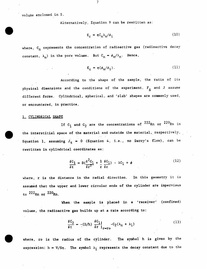
volume enclosed in S.
Alternatively, Equation 9 can be rewritten as:
^ - ^nV^i (10)
where, C represents the concentration of radioactive gas (radioactive decay
constant, \^) in the pore volume. But C^ - ^n/^n- Hence’
^ - ^V^i)- (n)
According to the shape of the sample, the ratio of its
physical dimensions and the conditions of the experiment, F and J assume
different forms. Cylindrical, spherical, and ’slab’ shapes are commonly used,
or encountered, in practice.
i_ CYLINDRICAL SHAPE
977 970If Ci and �9 are the concentrations of -"Rn or Rn in
the interstitial space of the material and outside the material, respectively,
Equation 1. assuming J^ - 0 (Equation 4, i.e., no Darcy’s flow), can be
rewritten in cylindrical coordinates as:
fic! - D(62C1 + 1 i^l) - ACi + ^(12)
6t Tr^~ r fir
where, r is the distance in the radial direction. In this geometry it is
assumed that the upper and lower circular ends of the cylinder are impervious
to ^Rn or ^Rn.
When the sample is placed in a ’receiver’ (confined)
volume, the radioactive gas builds up at a rate according Co:
6Cn 6Ci i H3)��- -(DA) �� -C2(An+ AI)<iJ;
*t � 6r l^o
where, ro is the radius of the cylinder. The symbol h is given by the
expression: h - V/Sry. The symbol Ai represents the decay constant due to the
radioactive gas leaking from the detection system associated with the receiver
volume.
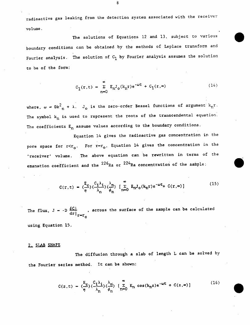
The solutions of Equations 12 and 13, subject to various
boundary conditions can be obtained by the methods of Leplace transform and
Fourier analysis. The solution of C^ by Fourier analysis assumes the solution
to be of the form:
C.(r.t) - ^ Vc/V)6’^ + ^^ (14)
n-0
where, u? - Dk2 + \. J^ is the zero-order Bessel functions of argument k^r.
The symbol k is used to represent the roots of the transcendental equation.
The coefficients E assume values according to the boundary conditions.
Equation 14 gives the radioactive gas concentration in the
pore space for r<r . For r-r^, Equation 14 gives the concentration in the
’receiver’ volume. The above equation can be rewritten in terms of the
emanation coefficient and the ^Ra or ^Ra concentration of the sample:
C(r,t) - (^X0^)^) ( 2 ^Ov)e-^ C(r.«)] <15^n ^ ^ n-o
The flux J - -D ^- across the surface of the sample can be calculated
^Ir-r,using Equation 15.
2_^ SlAB SHAPE
The diffusion through a slab of length L can be solved by
the Fourier series method. It can be shown:
C(z,t) - (!£) (c^.) (/<ri) [ S ^ cosOc^e-^ + C(z,-)] (16)
1 ^n ^n n-0
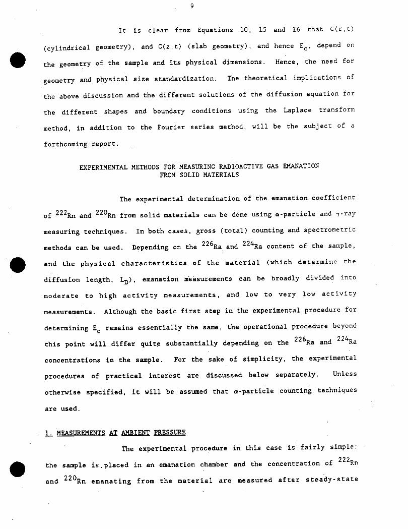
It is clear from Equations 10, 15 and 16 that C(r, c)
(cylindrical geometry), and C(z.t) (slab geometry), and hence E^, depend on
the geometry of the sample and its physical dimensions. Hence, the need for
geometry and physical size standardization. The theoretical implications of
the above discussion and the different solutions of the diffusion equation for
the different shapes and boundary conditions using the Laplace transform
method, in addition Co the Fourier series method, will be the subject of a
forthcoming report.
EXPERIMENTAL METHODS FOR MEASURING RADIOACTIVE GAS EMANATIONFROM SOLID MATERIALS
The experimental determination of the emanation coefficient
of ^Rn and ^Rn from solid materials can be done using a-particle and j-ray
measuring techniques. In both cases, gross (total) counting and spectrometric
methods can be used. Depending on the ^Ra and ^Ra content of the sample,
and the physical characteristics of the material (which determine the
diffusion length. LrO, emanation measurements can be broadly divided into
moderate to high activity measurements, and low to very low activity
measurements. Although the basic first step in the experimental procedure for
determining E remains essentially the same, the operational procedure beyond
this point will differ quite substantially depending on the Ra and Ra
concentrations in the sample. For the sake of simplicity, the experimental
procedures of practical interest are discussed below separately. Unless
otherwise specified, it will be assumed that oc-particle counting techniques
are used.
]_ MEASUREMENTS ^T AMBIENT PRESSURE
The experimental procedure in this case is fairly simple:
222the sample is, placed in an emanation chamber and the concentration of Rn
and ^^n emanating from the material are measured after steady-state
10
r) 0 7
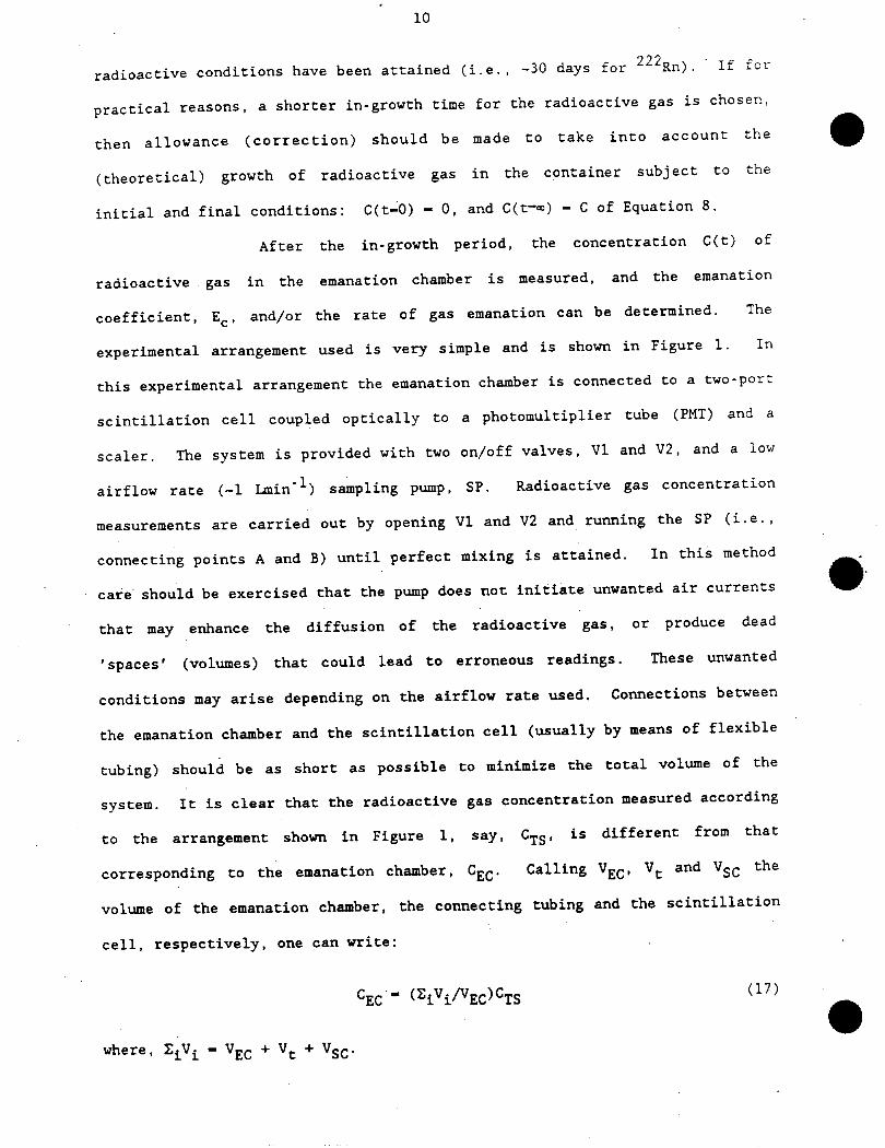
radioactive conditions have been attained (i.e., -30 days for Rn) . If for
practical reasons, a shorter in-growth time for the radioactive gas is chosen,
then allowance (correction) should be made to take into account the
(theoretical) growth of radioactive gas in the container subject to the
initial and final conditions: C(t-O) - 0, and C(t-«) - C of Equation 8.
After the in-growth period, the concentration C(t) of
radioactive . gas in the emanation chamber is measured, and the emanation
coefficient, E^, and/or the rate of gas emanation can be determined. The
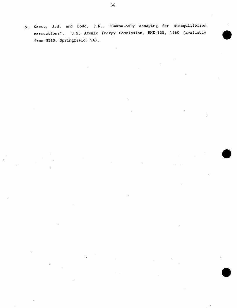
experimental arrangement used is very simple and is shown in Figure 1. In
this experimental arrangement the emanation chamber is connected to a two-port
scintillation cell coupled optically to a photomultiplier tube (PMT) and a
sealer. The system is provided with two on/off valves, VI and V2, and a low
airflow rate (-1 Lmin’1) sampling pump, SP. Radioactive gas concentration
measurements are carried out by opening VI and V2 and running the SP (i.e.,
connecting points A and B) until perfect mixing is attained. In this method
care should be exercised that the pump does not initiate unwanted air currents
that may enhance the diffusion of the radioactive gas, or produce dead
’spaces’ (volumes) that could lead to erroneous readings. These unwanted
conditions may arise depending on the airflow rate used. Connections between
the emanation chamber and the scintillation cell (usually by means of flexible
tubing) should be as short as possible to minimize the total volume of the
system. It is clear that the radioactive gas concentration measured according
to the arrangement shown in Figure 1, say. C^g. is different from that
corresponding to the emanation chamber, C^’ Calling Vg^, V^ and Vg^ the
volume of the emanation chamber, the connecting tubing and the scintillation
cell, respectively, one can write:
GEC-- (^i^EC^TS (17)
where. 2^ - V^ + YC + ^C-
From CF^(t). V^, t, and Equation 8, the emanation rate for
the radioactive gas from the sample can readily be calculated; and if the
concentrations of ^Ra and 22^ in the material are known (i.e. ,
radiochemical analysis or 7-spectrometry). the emanation coefficient. E^. can
be calculated.
In the experimental procedure outlined a sampling pump was
used to:
a) introduce a sample of radioactive gas into a scintillation cell at the
same pressure as the rest of the experimental apparatus, i.e., ambient
pressure;
b) circulate, stir, and hence, mix the radon-laden air in the emanation
chamber with the air in the" rest of the system to produce a homogeneous
radioactive gas concentration throughout the experimental apparatus;
An alternative Co the above procedure is to have VI- and V2
closed, points A and B disconnected, i.e., pump not running and take a sample
of gas from the emanation chamber at a convenient time (by opening VI or V2)
by means of an evacuated scintillation cell. If this procedure is followed,
the following should be considered:
a) Vgc is small compared with Vg^. If this conditions is not satisfied the
pressure differential created during the taking of the sample can enhance
emanation of radioactive gas from the interstitial space of the sample by
transport (convective) mechanisms;
b) the counting efficiency of a scintillation cell is dependent on the
pressure in the cell when the physical dimensions of the latter are larger
than the range of the a-particles in the cell volume. Hence, if the final
pressure of the cell after the sample of radioactive gas has been
completed is less than ambient, i.e.. the case of reduced pressure,
corrections to the counting efficiency will be necessary. This elementary
fact is quite frequently overlooked and can lead to significant errors in
12
the calculation of E^ and emanation rates.
The experimental procedure discussed above is only applicable
to cases in which the concentrations of ^Ra and ^Ra in the material are
moderate or high. In these cases, only elementary care and precautions in
carrying out the measurements are necessary. However, when the concentrations
of ^Ra and ^Ra are low or very low, then special precautions have to be
taken to ensure meaningful and reliable measurements. In this case special
attention should be paid to the materials used in- the design of the
experimental apparatus used, i.e., these materials should have the lowest
possible emanation rates (lowest ^Ra and ^Ra content possible). In
addition, improved techniques for the collection of the radioactive gas should
be developed to increase the signal Co noise ratio, i.e.. true emanation rate
from the material as compared with the emanation rate, or background, from the
materials used in the construction of the experimental system. Adsorption
losses of the radioactive gas onto the surfaces of the materials used in the
experimental system is also a serious consideration. A method developed for
measuring very low emanation rates of ^Rn and ^Rn from materials is
described and discussed below.
2__ MEASUREMENTS UNDER VACUUM CONDITIONS
Measurements of radioactive gas emanation from samples
"5 9 ft
under vacuum conditions are suitable for materials of low and very low Ra
and ^Ra content (2.3). However, it should be stressed that measurements
under vacuum conditions do not truly represent normal or natural conditions.
This is so because an artificial pressure differential between the sample’s
interstitial space and the volume external to the sample is imposed. Under
these conditions, the usual expressions describing pure diffusion processes no
longer apply because the emanation of radioactive gas from the sample is
governed by forced convective transport processes, in addition to pure
diffusion mechanisms. Under these conditions, the simplification J^ - 0 (no
Darcy’ s flow) is no longer possible, and Equations 12 to 16 are no longer
valid in the present case. Hence, Equation 1 must be solved taking into
account Equations 2, 4 and 5, where 7P can be described by a step function.
However, the solutions to Equation 1 for VP /O is beyond the scope of this
report.
Another important consideration when measuring radioactive
79 fi 77Zigas emanation rates from materials of low or very low Ra and Ra concent
is the adsorption of ^Rn and ^Rn on large surfaces. Three cases are of
interest in the context of this discussion, namely, adsorption of radioactive
gas:
1. On the surface of the emanating material (sample);
2. Upon contact of the sample with ’laboratory air’ before placing the sample
in the emanation chamber (see below);
3. On the surfaces of components of the experimental apparatus.
999 770In all of the above cases, the "�"’-Rn and ""Rn are, in
222 220part, irreversibly adsorbed. Data on adsorption of Rn and- Rn on
material surfaces is virtually non-existent, and a subject of interest
worthwhile investigating in some detail. Items 1 and 3 will result in
underestimating the emanation rate of radioactive gases from the samples.
However, item 2 will result in the opposite, i.e., overestimation of the
emanation rate. Items 1 to 3 are not the only complicating factors to content
with. Another difficulty arises when the porosity of the material and the
’mechanical layout or configuration’ of the sample are taken into account. In
the first case, ^Rn can diffuse into the sample (reverse or back-diffusion)
upon contact with ’laboratory air’, prior to inserting the sample into the
emanation chamber. Part of the ^Rn may remain trapped in the pore space
until it decays away. In the second case, ^Rn entering samples, arranged in
layers of different materials, may be trapped between layers and diffuse
through the layers slowly, and so on. (For ^Rn the above effects can be
14
safely disregarded because of its short half-life, -56 s.)
A further consideration when measuring low emanation rates
is the ^^Ra and ^^Ra content of the materials used in the experimental
apparatus, e.g.. emanation chamber. Cubing, cold traps, valves, scintillation
cells and vacuum gauges, to name a few components. Hence, materials should
be chosen for the components of the system with the minimum possible amount of
^Ra and ^Ra. If the content of these radionuclides in the system is
significant, in other words easily measurable, then estimation of emanation
rates will not be an easy task.
The discussion above suggests that measurements of
emanation rates and emanation coefficients of materials under vacuum
conditions are rather complex, delicate, and time consuming. In general, the
experimental procedure used in this method can be summarized in the few steps
below. However, because this is the method and procedure followed in
obtaining the emanation rates data presented in this report, the experimental
procedure used, as well as the different components of the experimental
apparatus (hereafter referred to as the emanation system, or the system, for
short) will be described in detail elsewhere in this report. The main steps
followed in the emanation method under vacuum conditions are:
1. Outgasing of the emanation system without the sample in place (i.e.,
emanation chamber);
2. Sample is placed in emanation chamber and the emanation system is
maintained under vacuum for a pre-set length of time. This operation is
done to remove ^^Rn: a) adsorbed on the surface of the material; b)
trapped in surficial pore spaces; c) trapped between layers of different
materials making up the sample, etc. Items a) to c) occur when the sample
is in contact with ^Rn-laden atmospheres, e.g., ’laboratory air’, for a
prolonged-period of time;
3. The emanation chamber is disconnected from the rest of the emanation
1->
system, and the radioactive gas in the sample is left to diffuse out of it
into the emanation chamber. The latter is designed to maintain the vacuum
conditions prevailing in the emanation system previous to disconnecting
the emanation chamber from the rest of the system, with minimum leakage.
This operation is commonly referred to as the in-growth period;
4. After a given in-growth period the emanation chamber is ’reconnected’ to
the rest of the emanation system and the radioactive gas in the emanation
-chamber is collected in a liquid nitrogen (LN^) cold trap; and
5. The radioactive gas collected in the LN^ cold trap is released (by warming
the Cu-coil that makes up the cold trap) and transferred to the
scintillation cell. where the radioactive gas concentration is measured.
Because of the low radioactive gas concentrations to be
measured, the background of the emanation system, i.e., contribution without
the sample, plays an important role and should be known as accurately as
possible. For this reason, the procedure outlined in items 1 to 5 should be
carefully repeated without the sample. This contribution, i.e.. background,
should be subtracted from the results obtained when measurements are conducted
with the sample.
It is also important to carry out measurements with the
same sample for different in-growth times to verify that the growth of
radioactive gas concentration in the emanation chamber with time follows<
Equation 8. Non-conformance with Equation 8 is clearly indicative of a faulty
experiment or measurement, as veil as, or, effects, contributions, or
n iy o
mechanisms other than pure diffusion of, say, Rn from the sample.
Although the method described here has been classified
before as rather artificial, this method would be in perfect accordance with
situations in which materials were subjected to vacuum conditions as part of
f\ f\ r\
Cheir natural environment, and the emanation of, say. Rn, was of
importance. Such cases may not be difficult to envisage.
16
3_ MEASUREMENTS £1 THE LIQUID IMMERSION METHOD
Emanation of radioactive gases from solid materials
submerged in liquids, particularly water, is another case of importance, both
from the theoretical and the experimental standpoints (3). THe emanation
method used in this case is very similar to the method used under vacuum
conditions, except for some notable differences, e.g.:
1. The emanation system is kept at ambient pressure; hence.. no vacuum pump
is necessary (a slight variation of the method in which collection of
radioactive gas is done under vacuum conditions will be described below);
2. The emanation chamber if filled with ultra-high purity water. The sample
is immersed in the water and kept in the emanation chamber for a given.
period, i.e., the in-growth period. During this time, the radioactive
gas emanating from the sample will dissolve in the water, from which it
must be extracted;
3. The radioactive gas dissolved in the water is extracted by bubbling an
inert carrier gas such as He through the water for a length of time.
The rest of the experimental procedure is similar to the
previous case investigated (emanation under vacuum conditions) and uses,
except for the emanation chamber, the same emanation system and follows the
same analytical procedure.
In this method, special care must be exercised with regards
to the purity of the water and the gas carrier (He) used. In order to reduce
the background of the system, the water used should contain <1 ppm of
suspended solids, and have a resistivity of -18 Wl. This can be accomplished
by passing distilled water through a combination of ion-exchange and de-
ionizer columns, in conjunction with special ’final’ filters. This procedure
will eliminate the majority of the ^Ra and ^Ra content in the water.
Radon-222 dissolved in the water must also be removed before immersing the
sample in it. This can be done by bubbling He through the water. However,
17
because He is not Rn-free, the carrier gas is passed through a LN^ cold
999trap to remove any trace of Rn, before entering the emanation chamber.
Once the sample is placed in the emanation chamber and
after a given in-grovth period, the radioactive gas dissolved in the water can
999 9 90be extracted as indicated above, namely, by passing Rn- and Rn-free He.
However, the He/radioactive gas mixture exiting the emanation chamber will
contain Substantial amounts of water vapour which, for a variety of reasons,
must be removed from. the gaseous mixture before the radioactive gas is
collected in the LN^ cold trap. This can be done by placing a CO^ cold trap
at the exit of the emanation chamber, upstream of the LN^ cold trap.
If the emanation chamber is not large, it is possible to
’de-emanate’ the radioactive gas by applying a vacuum to the emanation chamber
(through the rest of the emanation system) so that the radioactive gas
dissolved in the water will bubble through.
Because of the special conditions under which measurements
are conducted in this particular type of experiments, the properties of water
as a solvent and leaching agent should be considered. The solubility and
teachability of the sample due to the prolonged action of the water acting
upon the sample are largely unknown, and some degree of interference with the
diffusion process should be expected. In addition, water can diffuse into the
interstitial pore space of the sample dissolving the radioactive gas diffusing
through the material. It is possible that this effect may retard the
diffusion process. Also some transport of radioactive gas mediated by water
is likely to occur. All these factors should be considered carefully. Hence,
the growth characteristics for the radioactive gas depicted by Equation 8 is
not likely to apply to the present case.
A final word of caution is in order. In this report,
frequent reference to radioactive gas is made as opposed to specific mention
of ^Rn or ^Rn. This is done because the methodologies described here
18
apply, in most cases, to radioactive gases with half-lives sufficiently long
for these experimental procedures to be effective. This is certainly the case
for ^Rn, but not for ^Rn, where its short half-life (-56 s) renders the
f\ r\ i o f\ r\
above procedures useless. However, � Ra and -- Rn must always be taken into
consideration because once ^Rn is formed, its progeny (��Bi and Po) can
seriously interfere with ^Rn measurements unless a-particle spectrometry is
used to discriminate ^Rn progeny from 222R�n and its progeny. Unfortunately.
the detectors suitable for a-particle spectrometry (e.g., silicon barrier,
SiB, and diffused-junction. DJ, detectors) have much lower a-particle counting
efficiencies than scintillation cells.’ (A well designed scintillation cell
can easily have an a-particle counting efficiency at least three times as high
as a conventional SiB or DJ detector, which have counting efficiencies of
approximately 20%.) Hence, what is gained in spectral information is lost in
r\ rtrt
a-particle counting efficiency. Fortunately. ��Rn progeny formed in the
emanation system plate-out most efficiently on the wall surfaces of the system
because of the low aerosol concentration, particularly under vacuum
conditions.
Radon-220 emanation measurements from solid materials are
difficult to carry out by the liquid immersion method. They are considerably
easier to conduct at ambient pressure, or under vacuum conditions, but the
emanation system used for ^^Rn emanation measurements must be modified
substantially. The easiest way to conduct ^^n emanation measurements is by
placing an a-particle detector in the emanation chamber and conducting
continuous, ’real-time’ measurements, either at ambient pressure or under
vacuum conditions. This technique, as well as some measurements conducted on
some materials, will be described in a forthcoming report.
Emanation measurements by the liquid immersion method are
of great practical interest, particularly with regards to the Sudbury Neutrino
Observatory (SNO). Measurements by this method will be the subject of another
19
forthcoming report.
U__ MEASUREMENTS BI GAMMA-RAY COUNTING
Finally, and for the sake of completeness a method for
determining the emanation of Rn from materials by. -y-ray counting will be
outlined briefly (^,5). This method has been used preferentially to determine
f\ f\ r\
the emanation coefficient of Rn from U-ore samples. This method is
commonly known as the Gamma-Only Assay Method, and it uses a NaI(Tl) -y-ray
detector and its associated electronic circuitry. (Other detectors, such as
High Purity Germanium, HPGe. detectors could of course also be used.)
The method consists of placing the sample in a suitable
small ’can’, and sealing the latter immediately after. The gamma-ray activity
is followed from t-0, i.e.. insertion of sample in can and sealing of the can,
until t-a>, i.e., steady-state conditions (several weeks) (5). In a modified
version, named the prediction method (4), two gamma-activity measurements are
made at suitable times after the sample is sealed in the can. From these
measurements, extrapolations are made to find the �y-ray activity at sealing
time (t-0). NQ, and at equilibrium (t�o), N^. Calling N^ and N^ the two
measurements at times ti and to, respectively, it can be shown that:
N3 - NI (18)N, - NI +1 - exp[-A(t^ - t^)]
No - N. - [N. - N^] exp [\(t^ - t^)] (19)
From Equations 18 and 19 the emanation coefficient. E^, can
be calculated:
EC - I1 - (NO/N.)] x 102 (20)
The emanation rate can be calculated from N^ (Equation 18).
The ultimate sensitivity of the gamma-only method depends a great deal on the
environmental gamma-ray background in the laboratory where measurements are
20
conducted. The sensitivity of the technique can be improved by adequate
shielding and by the use of high energy resolution 7-detectors such as HPGe
detectors. Although this method has not been used at our laboratory for very
low ^^Ra or ^^U content samples, it works reasonably well for conventional
U-samples. It is. however, doubtful that it would be sensitive enough,
because of high environmental 7-ray backgrounds, for our particular
application with regards to the SNO Project.
This report presents data obtained with the emanation
method under vacuum conditions. The following section is devoted to a
detailed description of the emanation system used, and the experimental
procedure followed for both, the calibration of the emanation system, and the
determination of emanation rates from materials. Data for three materials are
reported.
DESCRIPTION OF THE APPARATUS (EMANATION SYSTEM)
�
’
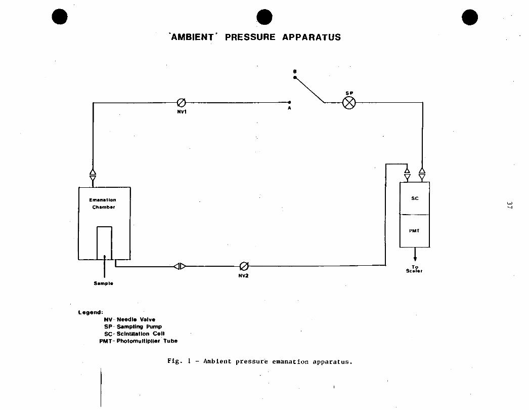
The vacuum emanation system used in this series of
measurements is shown in Figure 2. The system consists of the following
components:
1. An acrylic emanation chamber. There are several cylindrical chambers
available of different dimensions to accommodate different types of
samples and amounts of the material samples of interest. The dimensions
of the chambers range from 12.5 to 29 cm in diameter and 19 to 175 cm in
height, thereby covering a volume ranging from 3.6 L to -60 L. The
chambers are provided with 2 to 3 connecting or sampling ports fitted with
TM’quick-connectors’ of the Swagelok� type;
2. The gas emanated from the sample and released into the emanation chamber
during the ’in-growth’ period was directed to two cold traps (CT). One
cold trap contains ’dry-ice’ (CO^) in order to remove water vapour.
whereas the second CT, placed downstream of the CT(CO^), contains liquid
21
997 ? 70N9 (LNo^ co condense Rn and/or Rn;
3. All the steps of the experimental procedure are carefully pressure -
monitored by means of three vacuum sensors, and their associated vacuum
gauges, and two Hg-manometers. Each pressure (P) sensitive device is
strategically located in the emanation system ’train’ to accurately
monitor P during the different operations carried out in the experimental
procedure. The different steps conducted during the procedure are
effected by means of several needle valves, each designed to perform a
given function;
4. Radon-222 and/or ^^n are released from the CT(LN^) and transferred to
77 7the counting system. This operation is normally done using a Rn-free
carrier gas. e.g., He in our case. (The He is first passed through a LN^rt rt r\
fold trap to remove all traces of Rn.) The counting system consists of
a scintillation cell of the flow through type, operating in conjunction
with a photomultiplier tube (PMT) and an automated, fully programmable,
’sealer’. In cases where spectral information, and/or radioisotope
. discrimination are important, the gross a-particle counting system
indicated above (i.e., scintillation cell and associated PMT/scaler
system) has been substituted by a special electrostatic chamber, equipped
with a silicon barrier detector in conjunction with their electronic
circuitries and computer-based system;
5. The different components of the emanation system were connected together
by means of thin-walled metal tubing (3/8" O.D.). including elbows.
’tees’, unions, quick connectors, and so on. Three emanation systems have
been built which differ only in the tubing material used. The data
reported here were obtained using Cu-tubing. The other two systems were
TMconstructed using, respectively, stainless steel and Pyrex , A fourth,
recently built emanation system only differs in the size of the tubing,
unions, etc. This system was built with 1/8" O.D. Cu-tubing and is
22
significantly shorter and smaller than the others. This ’microsystem’ has
an internal surface area considerably smaller than that of the other
systems, and was designed to further reduce the a-particle background of
the emanation system. The idea behind using different materials was to
determine which had the lowest background to be used for very low
emanation studies;
TM
6. Other components of the emanation system include (flexible) Tygon tubing
which was found to be the most suitable for connecting the emanation
chamber and the scintillation cell to the rest of the system. Connections
between the different components of the emanation system were effected by
means of brass or stainless steel ’quick connectors’. This ’modular’
option provided the system with a great degree of flexibility as it was
very easy to reassemble, transpose and interchange components within the
same system, or from one system to another;
7. The cold traps placed in the emanation system (see item 2) differed in
size. shape and material. Usually, the cold traps used were of the coil-
type with about six complete turns and approximately 7 cm diameter. Cold
TMtraps were made of Cu, stainless steel, and Pyrex ; and
8. A vacuum pump at one end of the emanation system train provided the
desired vacuum for proper operation of the system. The pump was rated at
IxlO"4 Torr (1.33322 x 10’5 kPa)..
The experimental procedure followed to measure the
emanation of ^Rn (or ^Rn) by the vacuum method will be described in detail
elsewhere.
CALIBRATION OF THE EMANATION SYSTEM
The calibration of the emanation system can be divided into
three parts, namely:
1. Calibration of the detection system, e.g.. scintillation cell (SC), in
23
conjunction with the PMT and associated sealer (s) , or SC/PMT/S, for
short;
2. Measurement of the background of the system; and
222 2203. Determination of the efficiency of radioactive gas ( Rn. Rn)
transfer.
1. CALIBRATION OF THE RADIOACTIVITY DETECTION SYSTEM
The o-particle efficiency of the SC/PMT/S system depends on
the PMT/S settings (e.g., threshold, high voltage, and the like) and the
scintillation cell itself. Assuming .the PMT/S to be an invariant of the
system, the efficiency of the counting system mainly depends on scintillation
cell parameters such as shape, physical dimensions, and ZnS(Ag) coating
thickness. Calibration of scintillation cells is a standard, well known
procedure. However, for special applications, such as low-activity emanation
studies under vacuum conditions, special care must be exercised to take into
account a number of important factors as follows, usually, scintillation
cells are calibrated at ambient pressure conditions and at relatively high
^^n concentrations. However, in the present case measurements were
conducted either under vacuum, or reduced pressure conditions, or at ambient
or reduced pressure conditions in the presence of a carrier gas, such as He.
The counting efficiency of a scintillation cell depends on the pressure inside
the cell and the type of gas carrying the 222Ra. One way of eliminating this
dependence is by making the dimensions of the cell equal or smaller than the
range of the o-partlcle at atmospheric (ambient) pressure. However, this has
a drawback, namely, it reduces the total a-particle count because the total
amount of ^Rn Inside the cell is proportional to its volume. But it also
has an advantage: the background of the cells, which is proportional to its
internal total surface area. decreases with decreasing surface area.
In the present case, new scintillation cells of volume -280
cm3, filled with the ^Rn/carrier gas (He) mixture at atmospheric pressure
24
have been used. Under these conditions, the counting efficiency of the cells
799is greater than when the cells are filled with the -"Rn/air mixture at the
same pressure. This is so because the range of o-particles of a given energy
is larger for gases with low atomic number, such as He. than for gases such as
0^ and Nn, the main components of air. It should be noted than in addition to
the relatively large scintillation cells (-280 cm3) indicated above, much
smaller cells (-100 cm , and <50 cm ) have also been used under the same
conditions.
The a-counting efficiency, K, of scintillation cells vary.
as indicated above. with the cell volume and shape. For the scintillation
cells used here K was -1.45 cpm/pCiL (39.2 cpm/mBqm ).
1_ BACKGROUND OF THE EMANATION SYSTEM
The main contribution to the background, B, of the
emanation system arises from the ^Ra content (Bq/g) of the components of the
system (including the emanation chamber and the Scintillation cell), as well
as the total emitting (internal) surface -area of the system. Another
undefined potential contribution to the background may arise from adsorption
of ^Rn on the vails of the system, particularly from the calibration
procedure which usually necessitates the injection of significant amounts of
^^Rn, which may later desorb during emanation studies.
The background of the emanation system varies with time
depending on its use and the activity concentration measured. In general. B
91 n 91 nincreases with time due to the steady build-up of ^"Pb/’-’-Po from the decay
of the short-lived decay products of ^Rn. This contamination is very
undesirable because of its long half-life (-22 y). Hence, once the
contamination becomes appreciable, the scintillation cell must either be
discarded, or alternatively, the ZnS(Ag) coating needs to be removed and the
cell recoated again. The background may also change because of microleaks in
the system. Because the emanation system is under vacuum, air from outside
may find its way into the system, which even in small amounts may
significantly contribute to B. This type of contamination or contribution is
affected by environmental factors.
Background (B) measurements should be carried out
frequently and extensively, i.e., for extended (continuous) periods. Accurate
measurements of B are critically important for the precise assessment of
emanation rates from materials. These measurements should be conducted under
the same conditions, i.e., in-growth period, and experimental procedure, as
the ’real’ emanation study except that no sample should be inserted in the
emanation chamber. Thus far. B measurements have been conducted quite
frequently over the last seven months for periods ranging from 1 day to
several weeks. The range of values found for B depended on the emanation
chamber and scintillation cell (type and volume) used. An average value for
the background of the total emanation system ^16 counts per day (cpd) has
been measured.
3.. TRANSFER EFFICIENCY FOR THE RADIOACTIVE GAS
Not all the radioactive gas emanated from the sample into
the emanation chamber reaches the a-particle detector, e.g.. scintillation
cell. There are several reasons for this:
a) Part of the radioactive gas is irreversibly adsorbed on the walls of the
emanation chamber and other components of the emanation system, including
the cold traps. Although direct measurement under our experimental
conditions of adsorption phenomena Is not straightforward, this effect
could conceivably be significant for ’low-emanating’ materials where the
signal-to-noise count ratio is rather low;
b) Not all the radioactive gas ’trapped’ in the cold trap can be transferred
to the scintillation cell. This is mainly due to two reasons, depending
on whether the transfer is effected under vacuum (or reduced pressure)
conditions, or. alternatively, using a carrier gas. such as He, to effect
26
the transfer. In the first case, insufficient pressure (vacuum)
differential between the cold trap and the scintillation cell is
responsible for inefficient transfer, whereas in the second case the mosc
probable cause is an insufficient amount of carrier gas to ’push’ all the
radioactive gas from the cold trap to the scintillation cell, hence part
of the radioactive gas remains in the ’in-between’ space (tubing, and so
on) .
The transfer efficiency of the emanation system can be
determined by injecting a known amount of ^Rn into the (empty) emanation
chamber and following the usual experimental procedure for the measurement of
^^Rn emanated from samples, by the vacuum method. Special precautions should
be taken in the transfer procedure to minimize sources of error, namely, a
given amount of ^Rn from a standard source is transferred into a well
calibrated scintillation cell. i.e.. cell A. and the o-particle count of cell
A is recorded carefully by an independent counting system. Sl, before
injecting the sample into the empty emanation chamber. After the transfer has
been completed, cell A is counted again in the counting system Sl. This
997operation is important in order to verify that all the Rn in cell A has
been transferred to the emanation chamber. If this is not the case. the
fraction of the total amount of 2�22^.n in cell A transferred to the emanation
chamber should be known accurately. It should be noted that because of the
plate-out of ^^Rn progeny on large surfaces. such as the walls of
scintillation cells, the second measurement of cell A should be done about 4 h
after the ^^Rn transfer to the emanation chamber has been effected. The
999residual activity is due to the cell background and any Rn still remaining
in the cell.
Numerous measurements following the procedure described
above indicate that the average transfer efficiency for the system used here
is, e(tr) -0.85 (i.e., -85%). (Subsequent modification in the system gives
27
correspondingly higher values for e(cr).)
FURTHER COMMENTS ON THE CALIBRATION OF THE SYSTEM
Subsections 1 (Calibration of the Radioactivity Detection
System), 2 (Background of the Emanation System), and 3 (Transfer Efficiency
for the Radioactive Gas) of this section are the main considerations regarding
the calibration of the emanation system. Hence, the a-particle count, N^,
obtained with the a-particle counting system of the emanation apparatus must
be corrected for:
1. Background, B;
2. a-partide counting efficiency of the scintillation cell/photomultiplier
tube/sealer (SC/PMT/S) system. K; and
3. Transfer efficiency e(tr).
Neglecting effects other than the ones discussed above, one
may write for the true a-particle count from the sample, i.e., Ng:
Ng - (N^ - B)/K e(tr) (21)
If N and B are given as count rates (e.g. , counts per
-a _ iminute, cpm) and K in terms of cpm/Bqm , Ng will be in Bqm" . Calling Vg^
the volume of the scintillation cell. the product Ng Vg^ (Bq) represents the
total emanated radioactivity resulting from the sample. i.e., A^. This
quantity must now be related to some ’extensive’ quantity of the sample, such
as volume, surface area or mass in order to properly quantify the emanating
characteristics of the sample. At this point it is important to be reminded
again of the effect of shape and physical dimensions on the emanating
characteristics of samples. For comparison purposes, this dependence can be
eliminated by preparing standardized, i.e., identical samples, from the
’geometry’ standpoint. However, it is clear that this is not always possible
because of practical considerations and constraints. Results from samples of
28
different geometries should be interpreted accordingly.
Expression- 21 presupposes that radioactivity measurements-
have been taken at, or after, steady-state conditions in the emanation chamber
have been reached, i.e. , t-tgg, where ss stands for steady-state. This
conditions is reached when e^^l- If t " ^G ^ss* where IG i^103^3 Ln-
growth period. Equation 21 should be modified accordingly by dividing by
’^IG. Again, the assumption is implicitly made that the radioactivity
measured arises from the decay of. say. ^Ra in the sample. But this does
r)r)r)
not necessarily need to be the case because the presence of Rn could be
ft t\ f
partly due to causes other than decay of Ra in the sample, namely:
1. ^^Rn adsorbed in the surface or pore space close to the surface of the
sample during contact with air;
2. ^^n trapped between layers of material if the sample is of the
multilayered type.
999Items 1 and 2 could not account for any Rn if the sample
"509 9 9 f\
was kept out of contact with any contaminating (’-�Rn. Ra) material, i.e..
if the sample is kept in the emanation chamber under vacuum, and radioactivity
measurements are carried out at times t»0.693/A. The latter quantity
represents the half-life of ^Rn. T^ C222^) -3-82 d. Hence, in order to
minimize the contribution of ^Rn from causes other than Ra in the sample,
measurements should be conducted at times OPT^y^2221^"1 month- However.
99fi 222this is approximately the minimum time necessary for the Ra - Rn mixture
to attain radioactive equilibrium (steady-state conditions). I.e.. tgg. It is
clear from the above, that at least one measurement of the sample should be
conducted at t >t (-8 w) to eliminate the potential contribution from
222’surface’ contamination by adsorption or back diffusion of Rn.
EXPERIMENTAL RESULTS AND DISCUSSION
Extensive measurements on three materials, Vlton ’O’-ring;
29
coaxial cable by Belden, M9067; and a molecular sieve (zeolite) have been
completed, and tests on other materials (norite, and several concrete
mixtures) are in progress. Measurements on each material were carried out for
different in-growth periods ranging from 4 to 58 days, for coaxial cable, to 1
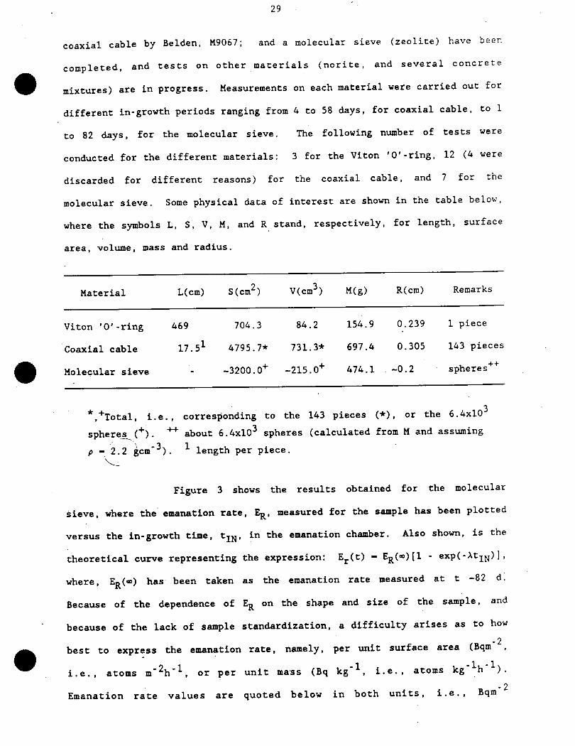
to 82 days, for the molecular sieve. The following number of tests were
conducted for the different materials: 3 for the Viton ’O’-ring, 12 (4 were
discarded for different reasons) for the coaxial cable, and 7 for the
molecular sieve. Some physical data of interest are shown in the Cable below,
where the symbols L, S. V, M. and R stand, respectively, for length, surface
area, volume, mass and radius.
Material L(cm) S(cm2) V(cm3) M(g) R(cm) Remarks
Viton ’O’-ring469704.384.2154.90.2391 piece
Coaxial cable17.514795.7*731.3*697.40.305143 pieces
Molecular sieve--3200.0’*’-215.0’1’474.1-0.2spheres’1’"1’
^Total, i.e. , corresponding to the 143 pieces (*) . or the 6.4x10
spheres (+). ++ about 6.4xl03 spheres (calculated from M and assuming
p - 2.2 gem’3). 1 length per piece.
Figure 3 shows the results obtained for the molecular
sieve, where the emanation rate, E^, measured for the sample has been plotted
versus the in-growth time. t^, in the emanation chamber. Also shown, is the
theoretical curve representing the expression: E^.(t) - E^(«)[l - exp(-At^)],
where. Ep(«) has been taken as the emanation rate measured at t -82 d.
Because of the dependence of E^ on the shape and size of the sample, and
because of the lack of sample standardization, a difficulty arises as to how
.^best to express the emanation rate. namely, per unit surface area (Bqm ,
i.e.. atoms m^h’1. or per unit ma-ss (Bq kg’1, i.e., atoms kg’ h ).
- 2Emanation rate values are quoted below in both units, i.e., Bqm
30
(atoms m^h’1) and Bq kg’1 (atoms kg^h’1). Furthermore, some uncertainty in
the specific gravity of the molecular sieve (Zeolite) (a value of 2.2 has been
taken), and the somewhat irregular shape of the molecular sieve particles
(spheres) , which leads to some uncertainty in the measurement of their
diameter, suggest that in the present case. the emanation rate per unit mass
provides a more accurate description of the emanating properties of the
material.
Comparison of experimental and theoretical data is best
accomplished by data normalization, a procedure which also eliminates the need
to express emanation rate data in terms of mass or surface area. The
emanation rate data at t-«, e.g.. t -82 d, permit the calculation of the
(approximate) ^Ra content of the sample. This calculation would give an
accurate value for the ^^a content if the emanation coefficient. E^, were
precisely known. However, because of the relatively small size of the zeolite
spheres (-0.2 cm), some assumptions can be made. Recalling that the diffusion
length, LQ. is given by (D/f?A)1/2. a review of the values for D in the
literature suggests, D > 10’6 cn^s’1. Hence. Lp »0.2 cm, and E^ -1. Taking
the above into consideration, the ^Ra content in the sample can simply be
calculated from the ^^n emanation rate at t-fi (i.e. . steady-state
conditions) from the equality: iK^Ra) \ (^Ra) - NC^Rn) \ (^Rn), where
the right hand side of this expression has been experimentally determined as
628 – 36 atoms kg^h’1 (see table below).
Theoretical principles and the data of Figure 3 show that
to estimate the true value of En, Rn measurements should be made at in-
growth times >20 d. If a shorter in-growth period is chosen, the value
obtained for E,, should be corrected (i.e.. divided) by the cotrection factor
l-exp(-Atj^), where tj^ is the in-growth time. However, the simplified
procedures indicated above are not recommended because the value estimated for
ER would depend on a single measurement only. The recommended procedure is to
31
measure En for at least three in-growth times, one possibly for tj^ 5 20 d,
and verify that the curve drawn through the data points is in agreement with
theoretical expectations.r\ t^ /_
Finally, it should’^be noted that the value for the Ra
content in the sample, i.e.. [ Ra], calculated as indicated above is
approximate, suitable only for illustration purposes. In actual practice,
[^^Ra] is usually assayed by wet chemical separation procedures followed by
-y- and/or a-spectrometric measurements. In some cases, however, direct
spectromecric measurement of the bulk material, i.e., entire sample, is made,
This method is, in most cases, not reliable enough.
Measurements on the coaxial cable showed certain
inconsistencies of, as yet, not clearly defined origin. It would appear that
after some evacuation periods, which usually lasted between 24 to >48 h (see
below), the emanation rate measured, after a given in-growth time, would drop
markedly as compared with the values obtained in the previous experiment.
This behaviour is consistent (at least partly) with the notion that:
a) An undefined fraction of the " Rn measured is not due to the radioactive
decay of the ^^Rn trapped between the different layers of material making
up the cable;
b) Part of the ^Rn measured arises from adsorption of the radioactive gas
on the material (coaxial cable) surfaces;
n n n 276c) All, or part of the Rn measured originates from the decay of the Ra
in the material, but its diffusion out of the sample is complicated by
(and depends on) the different diffusion coefficients making-up the
materials of the coaxial cable, and the air space thickness between the
layers. All these complicating factors will result In rather complex
^Rn release characteristics which could conceivably depend on the
measurement cycle. I.e.. evacuation period, in-growth period, and hence.
time elapsed between measurements.
32
Items a) and b) depend on the exposure (to air) history of
222the sample, but the effects should become negligible after about 6T^y^ Rn^
"23 d, unless the sample is again exposed to air between measurements.. The
effect of sample exposure to air is simply measured by placing the exposed
sample in the emanation chamber, as if it had gone through the evacuation and
in-growth periods procedure, and then proceeding in the usual manner, as
described elsewhere in this report. This was done shortly after the sample
had been received and had been exposed to air by an undetermined period. The
value measured for this contamination in terms of emanation rate was: 0.89 –0.31 atoms m^h’1. However, it should be noted that an undefined amount of
^Rn (trapped between the layers or in the layers) must also have come from
the decay of ^Ra in the material. Additional measurements conducted shortly
after the ’contamination’ experiment suggest that a large fraction of the
radioactivity measured must have come from air contamination. In summary, one
may surmise from the above discussion that item c) plays a key role.
The term evacuation period has been introduced above. This
is an important operation in which the sample is placed in the emanation
chamber, and the latter is evacuated for a given period. This operation is
conducted to remove any residual ^Rn trapped in the sample, e.g., in the
pore space and on the surface of the material, before the actual in-growth
period begins. However, because of the different porosities, permeabilities,
^00-
and hence, diffusion coefficients, and diffusion lengths of z" Rn in different
materials, the period required in each case for each material or array of
materials is different. This poses a serious problem that should be
investigated in detail. Hence, evacuation period standardization, i.e., same
evacuation period for all samples, may not be the best solution as it could
result in unnecessary time constraints and other practical difficulties. The
question of how long an evacuation period is necessary in each case can be
resolved in two ways:
33
1. By monitoring the pressure of the system, where the sample is under
vacuum, until no further decrease in pressure by outgasing is observed^
This presupposes that the system is capable of detecting extremely small
variations in pressure;
2. By monitoring the Rn concentration in the system until ’background’
"597levels are attained. This method requires the ""Rn counting system to be
of the flow through continuous monitoring type, as the ones used at our
laboratories.
The second method has lately been adopted here. However,
many early measurements were conducted for arbitrary evacuation periods
ranging from 24 to >48 h. based solely on pressure variation (outgasing)
considerations.
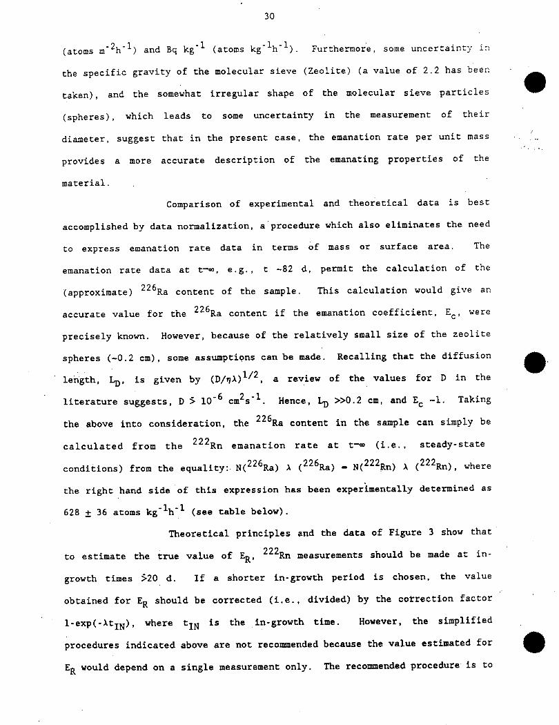
Figure 4 shows the emanation rate measured for the coaxial
cable for different in-growth periods. Also shown is the theoretical curve
for the same in-growth period. Extrapolation of the experimental data fort
t-«x», gives an emanation rate, En, for the coaxial cable of -0.31–0.13 atoms
m-V1.The last material to be reported here (but the first one of
the series to be investigated) is a length of Viton ’O’-rlng. This material
was mainly used to test several experimental procedures, and to run a variety
of tests in three different emanation systems made up of different materials
and components. However, no extensive series of measurements was conducted of
the emanation rate versus the in-growth time. The measurement reported here
was obtained for an in-grovth period of 3 days. The corresponding value for
t-fi was calculated as described by theory. Hence, the value given is
subjected to an undefined uncertainty. The emanation rate so obtained was
-1.02 – 1.12 atoms m^h’1.
The table below summarizes Rn emanation data for the
three materials investigated. In all cases, the emanation rate is given in
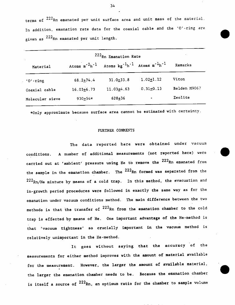
34
terms of ^^Rn emanated per unit surface area and unit mass of the material.
In addition, emanation rate data for the coaxial cable and the ’O’-ring are
given as ^^Rn emanated per unit length.
’799Rn Emanation Rate
Material Atoms m^h’1 Atoms kg’V1 Atoms m^h’1 Remarks
’O’-ring 68.2–74.4 31.0–33.8 1.02–1.12 Viton
Coaxial cable 16.03–6.73 11.03–4.63 0.31–0.13 Belden M9067
Molecular sieve 930–54* 628–36 - Zeolite
*0nly approximate because surface area cannot be estimated with certainty
FURTHER COMMENTS
The data reported here were obtained under vacuum
conditions. A number of additional measurements (not reported here) were
’?’99
carried out at ’ambient’ pressure using He to remove the Rn emanated from
the sample in the emanation chamber. The ^Rn formed was separated from the
^Rn/He mixture by means of a cold trap. In this method, the evacuation and
in-growth period procedures were followed in exactly the same way as for the
emanation under vacuum conditions method. The main difference between the two
methods is that the transfer of ^Rn from the emanation chamber to the cold
trap is effected by means of He. One important advantage of the He-method is
that ’vacuum tightness’ so crucially important in the vacuum method is
relatively unimportant in the He-method.
It goes without saying that the accuracy of the
measurements for either method improves with the amount of material available
for the measurement. However, the larger the amount of available material,
the larger the emanation chamber needs to be. Because the emanation chamber
is itself a source of ^Rn. an optimum ratio for the chamber to sample volume
35
is attained which maximizes the signal (S) to noise (N) ratio, i.e., S/N.
With this in mind, the use of the smallest emanation chamber that can hold the
sample is strongly recommended. If experimentally achievable, a S/N 5-10 is
desirable.
A number of materials other than the ones reported here are
presently being studied using the vacuum and the He-method. These materials
include norite, and several concrete aggregates which are important for the
977SNO Project. Also concurrently investigated, are the Rn permeability
characteristics of epoxy resins and other polymers. The ultimate goal of
222these studies is to determine the characteristics of these polymers as Rn
barriers when one or more coatings of these materials are applied to mine
walls (norite) and building materials (e.g., concrete aggregates) used in the
construction of structures for underground laboratory and other experimental
facilities. In this type of study, the emanation characteristics of norite
and concrete aggregates are investigated before and after coating the samples
777with epoxy resin, or other suitable Rn barrier material. The study of the
^^Rn emanation characteristics of the material in bulk, and after having been
crushed and ground is also of great practical interest.
REFERENCES
1. Welty, J.R., Wicks, C.E. and Wilson, R.E., Fundamentals of Momentum, Heat
and Mass Transfer. John Wiley and Sons; New York, 1976.
2. Liu, Q.M.. M.Sc. Thesis, Queen’s University. 1991.
3. Lee, H., Sur, B., McDonald, A.B., Private communication, 1991.
4. Austin. S.R. and Droullard, R.F., "Radon emanation from domestic uranium
ores determined by modifications of the closed-can, gamma-only assay
method"; U.S. Bureau of Mines Report of Investigation, RI 8264, U.S.
Dept. of the Interior. 1978.
36
5. Scott, J-H. and Dodd, P.N., "Gamma-only assaying for disequilibrium
corrections"; U.S. Atomic Energy Commission. RME-135, 1960 (available
from NTIS. Springfield, VA).
AMBIENT’ PRESSURE APPARATUS
SP
i
Em
C»
1
�nallc
^�mbfl
>n
r
’ ^l^01
NV1A
A LY \
SC
PMT
ISc«f«r
NV2
Sample
Legend:NV Needle ValveSP- Sampling Pump
SC Scintillation Cell
PMT- Photomultlplier Tube
Pig. 1 - Ambient pressure emanation apparatus
VACUUM EMANATION APPARATUS
M*dlum KM«diufH rrfl* KLarg*
Emanation Chambers
Legend:VG-CT-NV-
Hg-B-SC-
PMT-
Vacuum GaugeCold Trap
Needle Valve
Mercury Manometer
SclntiUation Cell
Photomultlplter Tube
Fig. 2 - Vacuum emanation apparatus
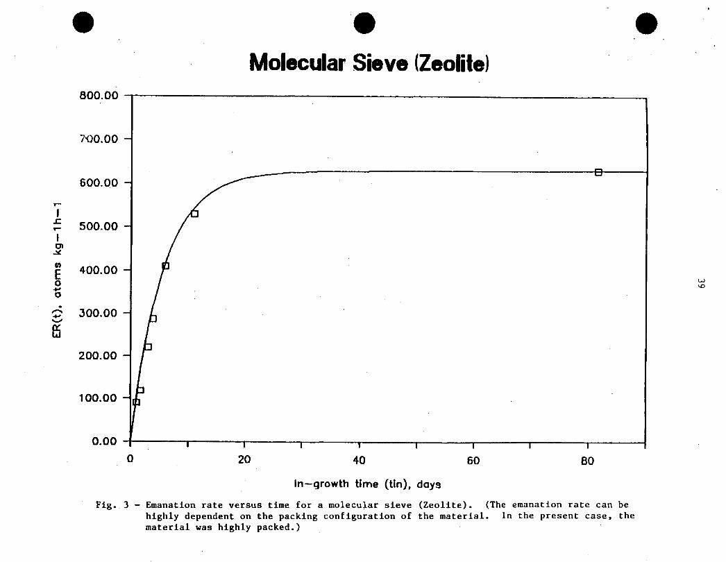
Molecular Sieve (Zeolite)
-&
0 20 40 60 80
In�growth time (tin), days
Fig. 3 - Emanation rate versus time for a molecular sieve (Zeolite). (The emanation rate can be
highly dependent on the packing configuration of the material. In the present case, thematerial was highly packed.)
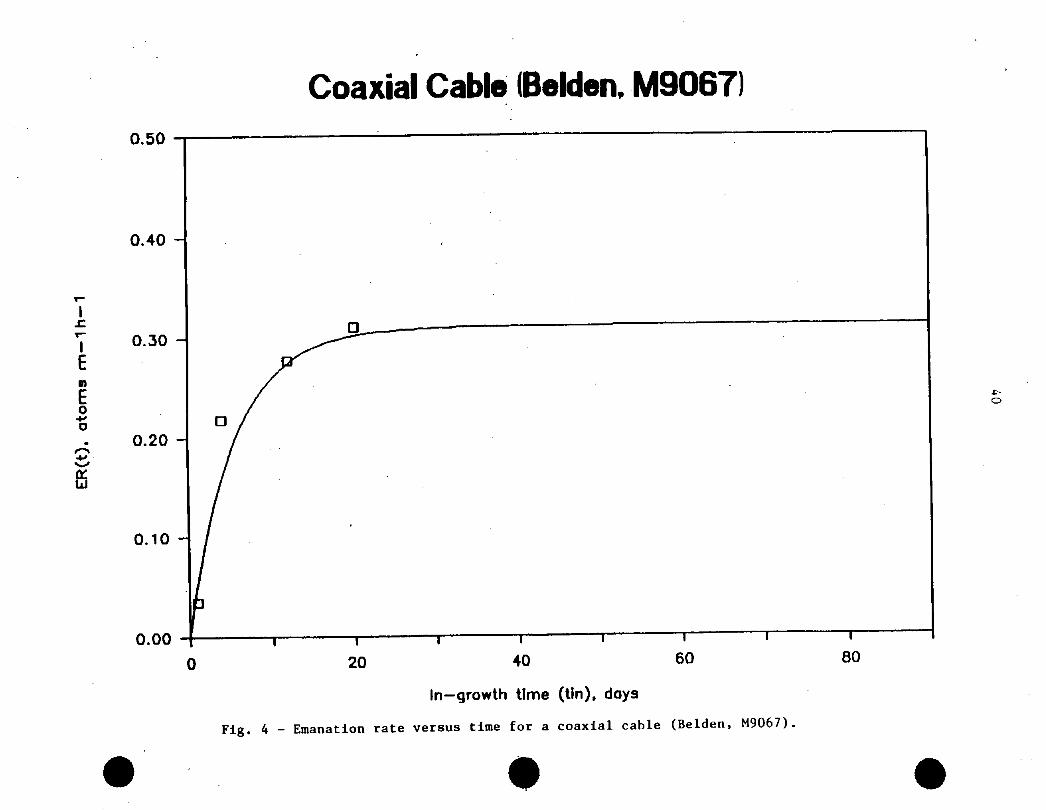
Coaxial Cable (Belden, M9067)
0.50 -T�����������-����������-��������������������~~
0.00 H������|������I������I������I������I*’ ’0 20 40 60 80
In�growth time (tin), days
Fig. 4 - Emanation rate versus time for a coaxial cable (Belden, M9067).