Embed Size (px)
Citation preview

IES-5106M Integrated Ethernet Switch
Support Notes June 2011 Edition 1.0

Content General Application Notes .............................................................................................. 3
The comparison of IES serious models ........................................................................... 4
Cable wiring .................................................................................................................... 6
Key Application Scenario ............................................................................................... 10
Access Application Notes .............................................................................................. 11
Application Scenario 1 - Multi-Services on VLC line card ............................................. 13
IP Multicast Introduction .............................................................................................. 19
Application Scenario 2 – Configure IPTV on ELC ........................................................... 20
Troubleshooting Guide of IPTV application for IES chassis DSLAM .............................. 28
Configure IPv6 multicast packets pass through IES-5106M .......................................... 40
Application Scenario 3 - EFM SHDSL Solution ............................................................... 45
Application Scenario 4 - VDSL fallback to ADSL ............................................................ 59
Application Scenario 5 - DSL Bonding ........................................................................... 63

General Application Notes The IES is an IP-based DSLAM (Digital Subscriber Line Access Multiplexer) that connects subscribers to the Internet. As a high-performance yet compact platform, it conveniently gives telephone companies and Internet Service Providers (ISPs) the ability to deliver broadband Internet access and voice services to subscribers. The IES platform allows for convenient management and support of various technologies. As the IES serious models, IES-5106M provides different DSL port speeds to different subscribers. In order to satisfy the different demand on connection requirement for the subscribers, an ISP might need to set different line speed for each DSL port. The IES-5106M can provide a proper solution to handle it by creating some profiles and setting different parameters for different users’ connections.

The comparison of IES serious models
Number of line cards
For different regions, number of subscribers, and the management on business budge and profit, the telephone companies and ISPs need a most economical and efficient DSLAM to cover their regional service. ZyXEL’s IES serious products provide various options of DSL solutions for ISPs and telephone companies to choose the best model which is suit for their business.
The IES-5106M can hold a maximum of five line cards, so up to 240 subscribers (360 when using the ALC1272 72-port line card) can simultaneously utilize a wide range of powerful broadband services.
Table 1. The comparison table with other IES models.
The ISP can deploy the IES-5106 for a moderate amount of subscribers regionally to gain the most benefit from using IES-5106.
The compatibility for MSC cards. As the various options for downstream line cards, the ISPs also have different requirements on the upstream links, such as Gigabit Ethernet port, Gigabit Ethernet SFP slot, Gigabit Ethernet XFP slot, or even 10 Gigabit Ethernet SFP+ slot. IES-5106 supports MSC1024GB and MSC1224GB serious management cards. Each management card has its own features for different uplink requirements and also has different features to other serious management cards, such as MSC1024G and MSC1224G.
IES-5106 IES-5012 IES-6000
number of total slot 6 12 17
number of management slot 1 2 2
max VDSL subscribers 240 480 768 max ADSL subscribers
(ALC-1272) 360 720 1152

MSC1024G MSC1024GB MSC1224G MSC1224GB
IES-5106M support No Yes No Yes
Ethernet port 2 2
SFP slot 4 2
Ethernet port/SFP slot
2 4 2 4
SFP+ slot 2
XFP slot 2
Table 2. The comparison table of management cards. The ISPs and telephone companies is able to choose a proper management card to perfect suit for their uplink network and has the best match to obtain the convenience and high quality connection in their deployment.

Cable wiring Cable wiring for IES-5016M
For the IES-51 06M, If you are using 48-port line cards, please use one IES-5005ST
splitter chassis and one IES-5002ST splitter chassis. If you are using 72-port line cards,
please use two IES-5005ST splitter chassis.
IES-5106M Front Panel Telco-50 Connections (with 5 Line Cards)

IES-5106M Front Panel Telco-50 Connections (with 72-port Line Cards)

Cable Wiring for ADSL line cards
Cable Wiring: Using SEC1024 for VOP1248G-61(IES-5000ST)

Cable Wiring: Using SEC1024 for VOP1248G-61

Key Application Scenario Multi-Service application Scenario
IES-5106M is compatible with ALC, VLC, ELC, SLC, IMA and VOP line cards, for different services. Therefore, IES-5106M is able to provide multiple services simultaneously, such as ATM, PTM, Ethernet and even VoIP service. The customer is able to use a single DSLAM, IES-5106M, to provide Multi-Service and gain the best benefit by choosing IES-5106M.

Access Application Notes
The following procedure describes the most typical operation of the IES-5106M using a browser. The IES-5106M features an embedded Web server that allows you to use Web browser to configure it.
- Set the static IP address on PC Before you connect the PC to manage IES-5106M, you need to set the PC with a static IP address as 192.168.0.x, and you are able to access IES-5106M from management port.
- Accessing the Web GUI
After plug the cable to management port, please enter the management IP address of the Web GUI in the URL location to retrieve the web screen from the IES-5106M. The default LAN IP of the device is 192.168.0.1. You would see a Security window asking the username and password for login.

- Log into IES-5106M via Web GUI.
Input the username and password to access the Web GUI (default username/password: admin/1234). You can see the initial System Info page on the screen as below, and then you are able to configure IES-5106M now.

Application Scenario 1 - Multi-Services on VLC line card The following example demonstrates a Triple Play service configuration running Data, VoIP, IPTV and TR069 services on respective WAN interfaces. The ISP can refer to this scenario to provide multiple services to its subscribers and also have the convenience and efficiency to maintain its devices and network. The following figure is a simplified overall scenario diagram of Multi-Service topology.
1. In this scenario, we use VLAN 695 for IPTV service, VLAN 696 for TR069 remote management, VLAN 697 for VoIP service and VLAN 698 for internet service.
2. Configure proper VLANs on IES-5106M: Go to VLAN. In the VLAN Setup page, enable the VLAN, set the name as “695”, set the VID as “695”, select “Fixed” for the uplink Ethernet port and select “Tag” for the uplink port as well. Click “Apply” to save the configuration.

3. Repeat step 2 to create VLAN 696, 697 and 698 with the same configuration except the name and VID. Please input the correct name and VID for each VLAN.
4. After creating these VLANs properly, you can find the created VLANs are displayed in the VLAN list. Please double confirm that these VLANs are set correctly with Tag.
5. Enable DSL port and set VLAN on DSL port: Go to Port -> VDSL, select the slot number of the VLC line card and the connect port to the CPE, and then click “Load” to load the current configuration on this port. In this case, the VLC line card in on slot #1 and the DSL port is #2.

6. Select “Enable” and click “Apply” to enable this port for DSL service. If the downstream CPE has connected to the VLC line card, the DSL LED should start to blink with orange light, which means that the physical DSL connection is working but the traffic is not through yet. The reason is that the VLAN setting is not finished.
7. Click VLAN “Setup” to set VLAN for this DSL port.

8. In page VALN Setup 1 – 2, input “695” for VID, select “join” for Registration and select “Tag”. And click “Apply” to add VLAN 695 for this DSL port.
9. Repeat step 8 for adding VLAN 696,697 and 698 with the same setting except the VID. Please input the correct VID for each VLAN.
10. After adding these VLANs properly, you can find the added VLANs are displayed in the VLAN list. Please double confirm that these VLANs are set correctly with correct VID and Tag.

11. In order to double confirm the VLANs are set correctly on this DSL port, please go to VLAN -> Port Setting, and click the slot number of the VLC line card.
12. You can see the VLAN setting is correct on the DSL port.

13. Now, the IES-5106M is able to pass through the traffic for both upstream and downstream with VLAN tags.
14. Please ensure that the VLAN setting on the switch and CPE are both correct, and then the traffic of different services would be directed to correct network and this scenario is able to provide multiple service on different WAN interfaces.

IP Multicast Introduction What is the IP Multicast? Traditionally, the IP packets are transmitted in two ways: unicast or broadcast. Multicast is a third way to deliver the IP packets to a group of hosts. Host groups are identified by the class D IP addresses, i.e., those with "1110" as their higher-order bits. In dotted decimal notation, host group addresses range from 224.0.0.0 to 239.255.255.255. Among them, 224.0.0.1 is assigned to the permanent IP hosts group, and 224.0.0.2 is assigned to the multicast routers group.
The IGMP (Internet Group Management Protocol) is the protocol used to support multicast groups. The latest version is version 2 (See RFC2236). The IP hosts use the IGMP to report their multicast group membership to any immediate-neighbor multicast routers, so the multicast routers can decide if a multicast packet needs to be forwarded. At the start-up, the Prestige queries all directly connect networks to gather group membership.
After that, the CPE updates the information by periodic queries. The device implementation of IGMP is also compatible with version 1. The multicast setting can be turned on or off on the Ethernet and remote nodes.
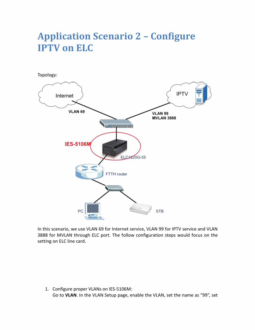
Application Scenario 2 – Configure IPTV on ELC Topology:
In this scenario, we use VLAN 69 for Internet service, VLAN 99 for IPTV service and VLAN 3888 for MVLAN through ELC port. The follow configuration steps would focus on the setting on ELC line card.
1. Configure proper VLANs on IES-5106M: Go to VLAN. In the VLAN Setup page, enable the VLAN, set the name as “99”, set

the VID as “99”, select “Fixed” for the uplink Ethernet port and select “Tag” for the uplink port as well. Click “Apply” to save the configuration.
2. Repeat step 1 to create VLAN 69 with the same configuration except the name and VID. Please input the correct name and VID for each VLAN.
3. After creating these VLANs properly, you can find the created VLANs are displayed in the VLAN list. Please double confirm that these VLANs are set correctly with Tag.
4. Go to Port -> Enet

5. Select Slot 3 and Port 1 (in this case, the ELC line card is in slot 3 and we use port 1 for downstream connection), then click ‘Load’ button.
6. Click VLAN “Setup” button to VLAN Setup: 3-1 page. Input PVID as 99 then click “Apply”. VLAN 99 would be displayed in the VLAN list below.

7. Go back to Port -> Enet, and select Slot 3 and Port 1 then click “load”. You can see that PVID has been set to 99. Select “Enable” then click “Apply” to enable this port.
8. Add a multicast VLAN 3888. When user send an IGMP join via VLAN 99, the DSLAM will change it to multicast VLAN 3888.
9. Go to Multicast -> MVLAN
10. Select “Enable”, set the Name as VLAN3888, VID as 3888, and then click “Apply” to add the MVLAN. VLAN 3888 would be displayed in the VLAN list below.

11. Click hyperlink “3” for the slot number of ELC line card, a new Web page will pop up.
12. Select “Fix” for port 1 which is the port on ELC for downstream connection, and then click “Apply”.

13. Click hyperlink “3888”, in the MLAN Setup page.
14. Add multicast address range which depends on the IPTV service. Here we use 224.0.0.0~239.255.255.255.

15. Go to Multicast -> IGMP.
16. In tag IGMP Setup, Select “Enable IGMP Snooping” for IGMP mode, and then click “Apply”.

17. Now, the setting of IGMP multicast service on IES-5106M is finished. If the VLAN setting on the uplink switch and downstream CPE are set correctly, the IPTV service with multicast group should work properly in this scenario.

Troubleshooting Guide of IPTV application for IES chassis DSLAM Introduction This troubleshooting guide introduces troubleshooting steps for field problems. If you do not find your problem in this document, please write down your problem with a clear description and send to [email protected] Tools & Equipment Before going into field to debug, here’s a list of tools and equipment to prepare before each trip: 1. Notebook with terminal emulation program, hyper terminal (open it in Windows OS
by Programs/Accessories/Hyper-terminal). 2. Console cable (DB-9 /9-pins, mal-to-female RS232 cable). Or use the USB-to-COM
port converter is also needed if your notebook does not provide any serial port connection.
Or 3. RJ-45 Ethernet cable, both straight & crossover 4. Software image (MSC& LT FWs), for both upgrade and regression download 5. ZyXEL DSLAM FW-Upgrade SOP 6. Packet trace recorder (such as, Wire-shark Tool, Sniffer NT) 7. L2 switch with both fiber and RJ-45 ports 8. IPTV probe 9. Functional MSC cards, line cards, Set-top Box and DSL CPE Before troubleshooting

When going to the field, collect the information below first before doing any debugging. 1. Current & History alarm 2. Abnormal LED status 3. MSC & Line-card versions, use command ‘lcman show’ 4. Complete network topology 5. DSLAM configuration file 6. DSLAM IGMP info 7. DSLAM CPU loading (polling at least ten times in ten minutes when problem
happens) 8. Team-viewer software or remote desktop access IP 9. CPE configuration In case remote access is needed, please add the following public IP when negotiating with end customer 1. 218.104.52.178 In order to resolve field problem at the earliest, provide the above-mentioned information while submitting technical support request to ZyXEL. To list the current alarm, go to [Alarm info SOP]. [Alarm info SOP]:
1. Use ‘cmd.exe’ in <Run> to open command windows in Win98/NT OS. 2. Telnet to <IP-address> of the DSLAM 3. Use command ‘alarm show’ to display the current alarm log 4. Use command ‘alarm history show detail’ to display the history alarm log 5. Capture the log & save it to TXT-file
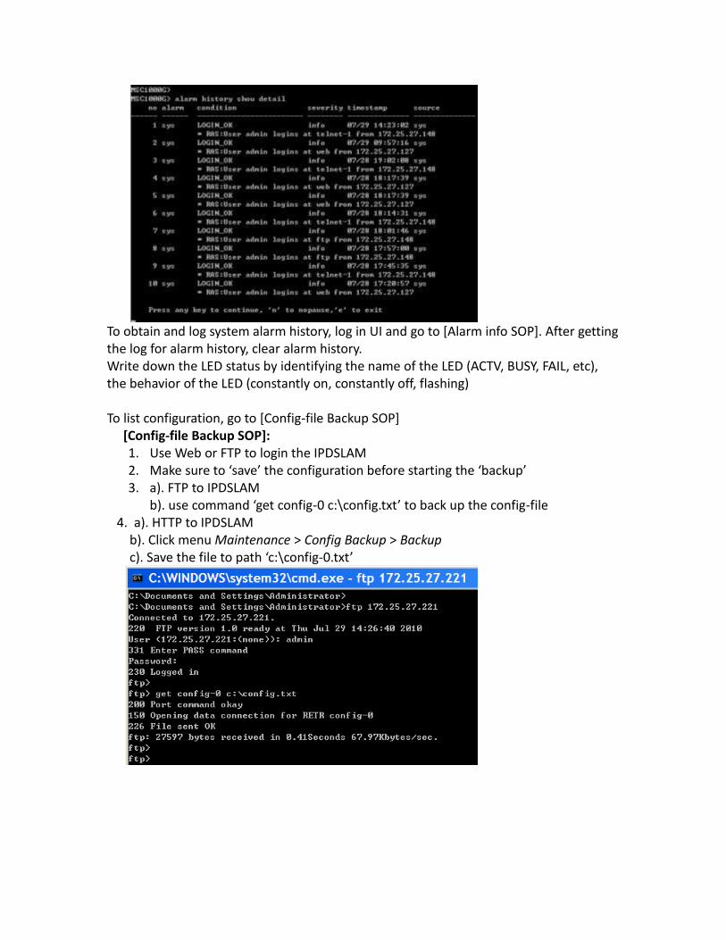
To obtain and log system alarm history, log in UI and go to [Alarm info SOP]. After getting the log for alarm history, clear alarm history. Write down the LED status by identifying the name of the LED (ACTV, BUSY, FAIL, etc), the behavior of the LED (constantly on, constantly off, flashing) To list configuration, go to [Config-file Backup SOP] [Config-file Backup SOP]:
1. Use Web or FTP to login the IPDSLAM 2. Make sure to ‘save’ the configuration before starting the ‘backup’ 3. a). FTP to IPDSLAM
b). use command ‘get config-0 c:\config.txt’ to back up the config-file 4. a). HTTP to IPDSLAM b). Click menu Maintenance > Config Backup > Backup c). Save the file to path ‘c:\config-0.txt’

MSC engineering mode Log in MSC’s command line interface, by either Console window or Telnet window, in there press ‘CTRL’ and ‘S’ keys at the same time on your computer, to enter engineering mode, if we issue the ‘?’ for help, there is no command prompt anymore. To exit engineering mode, press ‘CTRL’ and ‘S’ keys at the same time again on your computer.

Line card CLI mode To access CLI mode of line card, give command “lcman debug <slot #>” in MSC engineering mode. For example, to enter CLI mode with line card that is installed in slot 4, give command “lcman debug 4”. To return to MSC engineering mode, type “exit” command.
Freeze Descriptions:

Freeze means the TV holds and stops flowing. Freeze happens when IGMP packet is dropped or IGMP protocol is having problem. Freeze is not Mosaic. For Mosaic issue, please refer to Mosaic. Generic network topology
Diagnosis: Start by finding out the exact problem: Did the subscriber have freeze before? Did the freeze happen in certain channels? Or the freeze happened to random
channels? How long does the freeze last? How does the freeze stop? The freeze disappeared
by itself or subscriber must switch to another channel? Did the subscriber change the CPE or STB recently? What is the IGMP setting of CPE? Proxy or snooping? What is the IGMP setting of STB? IGMPv2 or IGMPv3? How long is the CPE IGMP query interval? How many STB are connecting to the CPE? One STB to one CPE or two STB to one
CPE? How many IPTV subscribers are there in the chassis DSLAM? How many IPTV channels are there in total? Is there any other traffic other than IPTV packet?
IPTV server
L3 switch
DSLAM
CPE
Set-top box

Possible Causes with Solution
Possible cause Solution
Source channel has delay
Please inform IPTV service provider
CPE setting is not compatible
Follow the setting of other CPEs
STB setting is not compatible
Follow the setting of other CPEs
DSLAM setting is not optimized
Please add static query VLAN for IGMP router
Two STBs connecting to one CPE
Please try line card FCS FW: 396UHA1C0 for ALC1272G-51
Freeze disappears by itself
Please try decrease the CPE query interval to be smaller than DSLAM’s. (150s ????)
If everything is ok, proceed with the following procedure. Symptom: Freeze is observed before DSLAM In this situation, we observed the Freeze on the STB connected to the L3 Switch directly.
Possible cause Outcome Solution
IPTV server
L3 switch
DSLAM
CPE
Set-top box Set-top box Set-top box

IGMP packet drop happens in the network
TV channel freeze
Inform IPTV service provider to check where the IGMP packet drop happens in the aggregation or in the core network
Symptom: Freeze is observed before CPE In this situation, the STB on L3 Switch is without Freeze; but the STB has Freeze which is connected to another uplink interface on DSLAM.
Possible cause Outcome Solution
MSC fails to handles all IGMP query
Freeze until next query arrives
Disable MSC CPU protection by giving command “eng ether bw switch 0”
MSC CPU utilization high
Freeze until CPU resource free-up
Give debug command “sys cpu disp” in MSC engineering mode, check the following picture
Line card CPU utilization high
Freeze until CPU resource free-up
Give debug command “sys cpu disp” in Line-card CLI mode, check the following picture
IPTV server
L3 switch
DSLAM
CPE
Set-top box Set-top box Set-top box

Symptom: Freeze is observed after DSLAM In this situation, both STBs on DSLAM and L3-Switch are without problem; but the STB behind the CPE has Freeze.

Possible cause Outcome Solution
CPE IGMP proxy/snooping compatibility
Freeze Change CPE IGMP setting; if it is proxy, please change to snooping. If the current setting is snooping, please change to proxy.
CPE IGMP version compatibility
Freeze Change CPE IGMP setting; if it is v2, please change to v3. If the current setting is v3, please change to v2.
CPE IGMP query interval not long enough
Freeze Increase CPE IGMP query interval
CPE is broken Freeze Replace old CPE with a new, functional one
Symptom-1: (Two or more TV channels) Freeze happens when other TV is switching to another channel; freeze disappears only after another channel switching e.g. Two TVs are watching the same channels, one TV switches the channel to another, another TV gets Freeze, unless it switches the channel too.
Possible cause Outcome Solution
STB did not Freeze Get trace between CPE & STB when freeze
IPTV server
L3 switch
DSLAM
CPE
Set-top box Set-top box Set-top box

handle the IGMP query correctly
happens. Freeze must be more than three times during trace recording.
DSLAM did not handle the IGMP query correctly
Freeze Try FCS FW version.
STB is broken Freeze Replace old STB with a new, functional one
Symptom-2: none of the above
Possible cause Outcome Solution
Unknown Freeze Get trace between CPE & STB when freeze happens. Freeze must be more than three times during trace recording.
Mosaic Descriptions: Mosaic means the part of the TV screen is showing Mosaic. Mosaic happens when packet is dropped within the network. Mosaic is not Freeze. Diagnosis: Start by finding out the exact problem: Is the IPTV subscriber also subscribing internet service? Is there any internet service/application running when Mosaic happens? What is the required bandwidth of the IPTV service? Is there any QoS to differentiate IPTV and internet traffic? How is the traffic performance when Mosaic happens? What is the performance of the CPE? Is there any CRC error? Does the Mosaic always happen in the same channel? Or Mosaic happens in all
channels? Possible Causes with solution
Possible cause Solution
CPE is broken Replace the old CPE with a new, functional one
Wire/connection is loose
Replace the cable or wire until there is no CRC error
Bandwidth limitation Please consult with IPTV or internet service provider if the actual bandwidth is lower than required bandwidth for IPTV service
No QoS between IPTV Give higher QoS for IPTV traffic, please refer to ATM

traffic and other traffic QoS feature for ALC/SLC-card solution, or refer to IPQoS feature for VLC / ELC-card solution. Please resort to CSO on ITS for the detail configuration if you have any question about the QoS setting.
If everything is ok, proceed with the following procedure.
Symptom: Mosaic happens during heavy traffic hour (peak hour)
Possible cause Outcome Solution
Packet drop due to heavy traffic
Mosaic Capture packet between CPE & STB, and between CPE and DSLAM, and between DSLAM and L2 switch at the same time, to see if there is any packet loss
Symptom: Mosaic happens during light traffic hour (non-peak hour)
Possible cause Outcome Solution
Bandwidth limitation policy
Mosaic Consult IPTV and internet service provider

Configure IPv6 multicast packets pass through IES-5106M
IPv6 uses multicast to replace broadcast in IPv4. That means there are only unicast packets and multicast packets in IPV6 traffic and no broadcast traffic in IPv6.
Static MAC Multicast Screen is designed for non-IPv4 static multicast traffic (such as IPv6 static multicast traffic).
DHCPv6 example:
unicast
unicast
multicast
multicast

Unicast can be studied easily by our DSLAM, there is no problem. However, in the sample, the corresponding IPv6 multicast MAC address is 33:33:00:01:02, this kind of MAC address is IPv6 multicast’s MAC address; it cannot be learned by DSLAM automatically. Therefore, we should add this MAC address into corresponding DSL ports and uplink ports. We suggest to add the following multicast into our DSLAM’s tested DSL ports: 1. 33:33:ff:[Last three bytes of PC MAC address] 2. 33:33:00:00:00:01 3. 33:33:00:01:00:02 (for DHCPv6) The following steps show how to configure IPv6 multicast packets pass through IES-5106M by Telnet connection:
1. Connect to the IES-5106M by Telnet and login as “admin/1234”. 2. Before starting configure IPv6 multicast packets pass through, we can type:
MSC1224BG> multicast groupmacaddr show

to check the Static MAC Multicast status.
As we can see, there is no Static MAC Multicast.
3. Add the IPv6 multicast address: 33:33:00:01:00:02 (for DHCPv6)for VLAN 1 for the uplink ports on MSC1224GB by typing: MSC1224BG> multicast groupmacaddr set 1 all fix

Then check the Static MAC Multicast status again, we can see that the uplink port on MSC1224GB (slot 6) are all fixed for VLAN 1.
4. Add the IPv6 multicast address: 33:33:00:01:00:02 (for DHCPv6)for VLAN 1 for all of the downlink ports on VLC1348G-51 (slot 1) by typing: MSC1224BG> multicast groupmacaddr set 1 33:33:00:01:00:02 1-* fix

Then check the Static MAC Multicast status again, we can also see that all of the downlink port on VLC1348G-51 (slot 1) are all fixed for VLAN 1.
5. We can also check the MAC Multicast status on GUI.
Go to Multicast -> Static MAC Multicast We can verify that the MAC address for IPv6 multicast is in the list of Static MAC Multicast and able to pass through IPv6 multicast packets.
6. Repeat steps 3 to 4 to add Static MAC Multicast for other IPv6 multicast address 33:33:ff:[Last three bytes of PC MAC address] and 33:33:00:00:00:01 to make IES-5106M able to pass through the IPv6 multicast packets.
Application Scenario 3 - EFM SHDSL Solution
Introduction
ZyXEL EFM SHDSL Solution helps Service Providers to have IP End to End Solution. Ethernet in the First Mile (EFM), also known as IEEE 802.3ah, is a collection of protocols specified in IEEE 802.3, defining the Ethernet in the access networks, i.e. first or last mile. With wide, metro and local area networks already standardized, the EFM allows continuous standard Ethernet network across the globe, eliminating non-native transport such as Ethernet over ATM from the access networks. EFM defines how Ethernet can be transmitted over new media types: Voice-grade copper. These new EFM copper (EFMCu) interfaces allow optional multi-pair aggregation Long wavelength single fiber (as well as long wavelength dual-strand fiber) Point-to-multipoint (P2MP) fiber. These new interfaces are known under collective name Ethernet over passive optical networks (EPON).

Network Topology:
Network topology is like above, the line card SLC1348G-22 is plugged in slot 1. Switch A, which connected to IES-5106M’s uplink port, and switch B, which connected to SLC line card, can ping with the VLAN header which is to similar the scenario that the service provider provided to the business customer. The management IP for Switch A is 10.10.10.1 with VLAN 200 The management IP for Switch B is 10.10.10.2 with VLAN 200

ATM Mode Configuration CO side:
1. VLAN settings in IES-5106M Create a new VLAN which VLAN ID is 200; enable Tx Tagging in Ethernet port which connected to the Ethernet switch A.
2. PVC settings:
Go to Port -> PVC, create a PVC VPI/VCI is 0/33 PVID 1 on the SLC (slot 1) port 1.

Click the index 1 link, below screen will appear, you can make the VPI/VCI 0/33 join the VLAN 200 and checked the Tag to make sure the traffic with VLAN 200 will be sent out with VLAN header.

3. Port setting Go to Port -> SHDSL, Slot 1 port 1, set the transmission convergence as “atm”.

ATM Mode configuration CPE side:
1. WAN Internet Access setup: Transfer Mode is ATM, Encapsulation is RFC 1483 and VPI/VCI is 0/33

2. 802.1Q/1P settings: Modify the default group 1 to enable Tx Tagging in LAN 1.

Create a new group name test, VLAN ID is 200, default Gateway is PVC1 and LAN 1 join this VLAN and Tx Tagging enabled. PVC1 also join this VLAN Tx Tagging enabled. PC A can’t recognize packet with VLAN, therefore for LAN 2, the Tx Tagging should not be enabled.

The final group status should like below:
3. Change the PVID for LAN port 2, change to VLAN 200 for PC A.

Test from Switch A:
In Switch A as you can see the IP settings and also test result of PING and the result is OK.

EFM Mode configuration CO
For EFM mode, there are three steps to finish the setting based on the ATM settings. 1. Change the Transmission Convergence mode to EFM in IES-5106M.

2. Change the Transfer mode to PTM in P-793H v2.
3. Modify the PVID for PVC setup page. Since in EFM mode there is no VPI/VCI, we still
need to use this page to define the PVID or default priority for the port. At the PVC setting page, click index link.

Same with the ATM mode setting, make PVC 0/33 join VLAN 200 and Tag must be checked to make sure traffic with VLAN 200 would be sent out with the same VLAN ID in VLAN header.

Test from Switch A:
In Switch A as you can see the IP settings and also test result of PING and the result is OK.

Application Scenario 4 - VDSL fallback to ADSL xDSL fall back provides the ISP increased interoperability with different xDSL CPEs and flexibility so they can now, depending on the distance and bandwidth requirements, offer different services to different customers using the same line card. In the following sample, we will show how to establish an ATM connection through a VDSL line card. Topology:
1. Go to Port -> VDSL, select the slot and port number for VLC line card and the port which connected to the CPE, and then click “load”. In this sample, the slot is 4 and port number is 1.

2. Enable this port and select mode as “adsl2+” in VDSL Profile, and then click “Apply”.
3. Go to Port -> PVC, select Slot 4 and Port 1 then click “Load” to load this port’s setting.
4. Set the PVC for this port as VPI/VCI as “0/33”, and then click “Apply”.

The setting for VDSL fallback to ADSL on IES-5106M is finished.
5. On the CPE, we can simple establish an ATM interface to verify if the fallback feature worked or not.
6. Create an ATM interface on the CPE with the VPI/VCI as “0/33”.
7. Then the CPE is able to establish an ATM connection to the internet through VLC line card by the feature of xDSL fallback.


Application Scenario 5 - DSL Bonding DSL Bonding Introduction
What is the DSL Bonding?
The basic theory behind bonding ADSL/VDSL lines is the idea that combining two separate ADSL/VDSL connections to connect to one computer should double your bandwidth and thus double your connection speeds. The solution currently being utilized is to connect two ADSL/VDSL lines to one router. For this to work, you need a specially designed router, such as the P-873HNUP-51B. ADSL/VDSL Bonding takes two copper based lines per subscriber and aggregates them to almost double the bandwidth speed available to the existing customers and also expands high speed broadband access to areas that are underserved today.
Using ADSL/VDSL Bonding technology, service providers can extend the life of their existing copper infrastructure supporting the delivery of bandwidth intensive services such as Triple play service, data and IPTV. Pair bonding isn't just about speed -- it's about reaching more customers at ever-greater distances.

Topology:
DSL Bonding configuration on IES-5106M 1. Go to Port -> ADSL, select the slot and port number for ALC line card and the
port which connected to the CPE, and then click “load”. In this sample, the slot is 2 and port number is 1 and 2; we would show the setting for port 1 first.

2. Click “Apply” to enable port 1.
3. Repeat steps 1 to 2 to enable port 2 as well.
4. Go to Port -> PVC, select the slot and port number for ALC line card and the port which connected to the CPE, and then click “Load”. In this sample, the slot is 2 and port number is 1 and 2; we would show the setting for port 1 first.

5. Set the PVC for this port as VPI/VCI as “0/33”, and then click “Apply”.
6. Repeat steps 4 and 5 to set PVC 0/33 for port 2 as well.
7. Go to Port -> G.bond
8. In the G.bond setup page, select the slot for ALC line card, in this case is slot 2, give this G.bond group a name as “test”.

9. Click the “none” link, the “Select Member Ports” page would pop up. Select the ports which we would like to bond together, and then click “Apply”. In this case, we bonded port 1 and 2.
10. The port 1 and 2 would be showed on the “Member Port” list. Click “Apply” to add the G.bond group.
11. The setting for G.bond on IES-5106M is finished.

DSL Bonding on CPE 1. Before we set the G.bond feature on IES-5106M, there is only one connection
established, and the bandwidth on the CPE (P-873HNUP-51B) is RX:23994/TX:999(Kbps).
2. After we set the G.bond feature on IES-5106M, the two ADSL connections are bonded together, and the bandwidth on the CPE (P-873HNUP-51B) is doubled to RX:47982/TX:1998(Kbps).