Embed Size (px)
Citation preview

IEEE Std 1609.1™-2006
IEEE Trial-Use Standard forWireless Access in VehicularEnvironments (WAVE)—Resource Manager
I E E E3 Park Avenue New York, NY 10016-5997, USA
13 October 2006
IEEE Vehicular Technology Society (VTS)Sponsored by theIntelligent Transportation Systems (ITS) Committee


The Institute of Electrical and Electronics Engineers, Inc.3 Park Avenue, New York, NY 10016-5997, USA
Copyright © 2006 by the Institute of Electrical and Electronics Engineers, Inc.All rights reserved. Published 13 October 2006. Printed in the United States of America.
IEEE is a registered trademark in the U.S. Patent & Trademark Office, owned by the Institute of Electrical and ElectronicsEngineers, Incorporated.
Print: ISBN 0-7381-5241-2 SH95580PDF: ISBN 0-7381-5242-0 SS95580
No part of this publication may be reproduced in any form, in an electronic retrieval system or otherwise, without the priorwritten permission of the publisher.
IEEE Std 1609.1™-2006
IEEE Trial-Use Standard for Wireless Access in Vehicular Environments (WAVE)—Resource Manager
Sponsor
Intelligent Transportation Systems (ITS) Committeeof theIEEE Vehicular Technology Society (VTS)
Approved 15 September 2006
IEEE-SA Standards Board
Abstract: This standard specifies a wireless access in vehicular environments (WAVE) dedicatedshort-range communications (DSRC) application, known as the WAVE resource manager (RM),designed to allow applications at remote sites to communicate with devices known as onboard units(OBUs), which are mounted in vehicles, through devices known as roadside units (RSUs), whichare mounted on the roadside. The WAVE RM, acting like an application layer, multiplexes thecommunications of multiple remote applications, each communicating with multiple OBUs. Thepurpose of the communication is to conduct information interchange, needed to implement therequirements of the remote WAVE DSRC applications.Keywords: DSRC, WAVE, resource manager

IEEE Standards documents are developed within the IEEE Societies and the Standards CoordinatingCommittees of the IEEE Standards Association (IEEE-SA) Standards Board. The IEEE develops its standardsthrough a consensus development process, approved by the American National Standards Institute, which bringstogether volunteers representing varied viewpoints and interests to achieve the final product. Volunteers are notnecessarily members of the Institute and serve without compensation. While the IEEE administers the process andestablishes rules to promote fairness in the consensus development process, the IEEE does not independentlyevaluate, test, or verify the accuracy of any of the information contained in its standards.
Use of an IEEE Standard is wholly voluntary. The IEEE disclaims liability for any personal injury, property orother damage, of any nature whatsoever, whether special, indirect, consequential, or compensatory, directly orindirectly resulting from the publication, use of, or reliance upon this, or any other IEEE Standard document.
The IEEE does not warrant or represent the accuracy or content of the material contained herein, and expresslydisclaims any express or implied warranty, including any implied warranty of merchantability or fitness for aspecific purpose, or that the use of the material contained herein is free from patent infringement. IEEE Standardsdocuments are supplied “AS IS.”
The existence of an IEEE Standard does not imply that there are no other ways to produce, test, measure,purchase, market, or provide other goods and services related to the scope of the IEEE Standard. Furthermore, theviewpoint expressed at the time a standard is approved and issued is subject to change brought about throughdevelopments in the state of the art and comments received from users of the standard. Every IEEE Standard issubjected to review at least every five years for revision or reaffirmation. When a document is more than fiveyears old and has not been reaffirmed, it is reasonable to conclude that its contents, although still of some value,do not wholly reflect the present state of the art. Users are cautioned to check to determine that they have the latestedition of any IEEE Standard.
In publishing and making this document available, the IEEE is not suggesting or rendering professional or otherservices for, or on behalf of, any person or entity. Nor is the IEEE undertaking to perform any duty owed by anyother person or entity to another. Any person utilizing this, and any other IEEE Standards document, should relyupon the advice of a competent professional in determining the exercise of reasonable care in any givencircumstances.
Interpretations: Occasionally questions may arise regarding the meaning of portions of standards as they relate tospecific applications. When the need for interpretations is brought to the attention of IEEE, the Institute willinitiate action to prepare appropriate responses. Since IEEE Standards represent a consensus of concernedinterests, it is important to ensure that any interpretation has also received the concurrence of a balance ofinterests. For this reason, IEEE and the members of its societies and Standards Coordinating Committees are notable to provide an instant response to interpretation requests except in those cases where the matter has previouslyreceived formal consideration. At lectures, symposia, seminars, or educational courses, an individual presentinginformation on IEEE standards shall make it clear that his or her views should be considered the personal views ofthat individual rather than the formal position, explanation, or interpretation of the IEEE.
Comments for revision of IEEE Standards are welcome from any interested party, regardless of membershipaffiliation with IEEE. Suggestions for changes in documents should be in the form of a proposed change of text,together with appropriate supporting comments. Comments on standards and requests for interpretations shouldbe addressed to:
Secretary, IEEE-SA Standards Board445 Hoes LanePiscataway, NJ 08854USA
Authorization to photocopy portions of any individual standard for internal or personal use is granted by theInstitute of Electrical and Electronics Engineers, Inc., provided that the appropriate fee is paid to CopyrightClearance Center. To arrange for payment of licensing fee, please contact Copyright Clearance Center, CustomerService, 222 Rosewood Drive, Danvers, MA 01923 USA; +1 978 750 8400. Permission to photocopy portions ofany individual standard for educational classroom use can also be obtained through the Copyright ClearanceCenter.

Introduction
This standard is based on IEEE Std 1455™-1999 [B4]a but intended for the 5.9 GHz frequency band. Severalchanges have been incorporated to accommodate the new requirements of the communication stackdescribed in the associated standards (IEEE Std 1609.2™,b IEEE P1609.3™, and IEEE P1609.4™ [B3]) andthe User Datagram Protocol (UDP) described in IETF RFC 768. As well, some inconsistencies and errors inIEEE Std 1455-1999 have been addressed.
This standard specifies a wireless access in vehicular environments (WAVE) application, known as theresource manager (RM), designed to allow applications at remote sites to communicate with devices knownas onboard units (OBUs), which are mounted in vehicles, through devices known as roadside units (RSUs),which are mounted on the roadside. The RM, acting like an application layer, multiplexes thecommunications of multiple remote applications, each communicating with multiple OBUs. The purpose ofthe communication is to conduct information interchange, needed to implement the requirements of theremote WAVE applications.
Notice to users
Errata
Errata, if any, for this and all other standards can be accessed at the following URL: http://standards.ieee.org/reading/ieee/updates/errata/index.html. Users are encouraged to check this URL forerrata periodically.
Interpretations
Current interpretations can be accessed at the following URL: http://standards.ieee.org/reading/ieee/interp/index.html.
Patents
Attention is called to the possibility that implementation of this standard may require use of subject mattercovered by patent rights. By publication of this standard, no position is taken with respect to the existence orvalidity of any patent rights in connection therewith. The IEEE shall not be responsible for identifyingpatents or patent applications for which a license may be required to implement an IEEE standard or forconducting inquiries into the legal validity or scope of those patents that are brought to its attention.
aThe numbers in brackets correspond to the numbers of the bibliography in Annex E.bInformation on references can be found in Clause 2.
This introduction is not part of IEEE Std 1609.1-2006, IEEE Trial-Use Standard for Wireless Access in VehicularEnvironments (WAVE)—Resource Manager.
Publication of this trial-use standard for comment and criticism has been approved by the IEEE. Trial-usestandards are effective for 24 months from the date of publication. Comments for revision will beaccepted for 18 months after publication. Suggestions for revision should be directed to the Secretary,IEEE-SA Standards Board, 445 Hoes Lane, Piscataway, NJ 08854, and should be received no later than13 April 2008. It is expected that following the 24-month period, this trial-use standard, revised andballoted as necessary, shall be submitted to the IEEE-SA Standards Board for approval as a full-usestandard.
Copyright © 2006 IEEE. All rights reserved. iii
Participants
The following is a list of participants in the Dedicated Short-Range Communications (DSRC) WorkingGroup.
Thomas M. Kurihara, Chair
The following members of the individual balloting committee voted on this standard. Balloters may havevoted for approval, disapproval, or abstention.
TiVon AbramsScott AndrewsLee ArmstrongJames ArnoldBroady CashKen CookSusan DickeyWayne FisherGamez GergesGloria GwynneChris HedgesRon HochnadelJason HunzingerDaniel JiangCarl KainPankaj KarnikDoug KavnerDavid Kelley
Brian KindPeter KofodJapjeev KohliRyan LammJerry Landt Jules MadeyAlastair MalarkyMira MarshallTim McGuickinJustin McNewYasser MorganJohn MoringRoss MorrisRichard NoensRoger O’ConnorPeter OomenSam OyamaFrank PerrySusan Proper
Mohan PundariEric RescoraRandy RoebuckRichard RoyTom SchaffnitDick SchnackeJerry ServissJohn SheppardRobert SoranoStephen Spenler Steve TenglerDan TerrierGlenn TurnockBryan WellsFilip WeytjensWilliam WhyteJijun YinJeffery Zhu
Satish K. AggarwalToru AiharaAdewole C. AkposeThomas AlexanderGerald W. AlthauserButch AntonLee R. ArmstrongCharles L. BarestJohn R. BarrSaman BehtashSean S. CaiJames T. CarloJuan C. CarreonBroady B. CashJon S. ChambersDanila ChernetsovElizabeth ChesnuttAik ChindapolKeith ChowJ. Kenneth CookTommy P. CooperCarlo DonatiSourav K. DuttaWayne K. FisherAndre F. FournierAvraham FreedmanH. M. GlickensteinSergiu R. GomaRandall C. Groves
Gloria G. GwynneRonald D. HochnadelWerner HoelzlDennis HorwitzRussell D. HousleyDavid HunterArshad HussainPeeya IwagoshiRaj JainOh JongtaekKevin J. KarczPankaj R. KarnikPiotr KarockiDouglas M. KavnerThomas M. KuriharaJeremy A. LandtSolomon LeeDaniel G. LevesqueJun LiuWilliam LumpkinsG. L. LuriJulius M. MadeyFaramarz MaghsoodlouJustin P. McnewGeorge J. MiaoGary L. MichelWilliam J. MitchellJohn T. MoringRoss A. Morris
Michael S. NewmanPaul NikolichRichard H. NoensSatoshi ObaraPeter OomenSatoshi OyamaSubburajan PonnuswamyVikram PunjPhilip T. RobinsonRobert A. RobinsonRandal D. RoebuckRandall M. SafierOsman SakrStephen C. SchwarmRich SeifertGerald K. ServissJohn W. SheppardRobert T. SorannoStephen J. SpenlerLuca SpotornoThomas J. TimchoGlenn TurnockMark-Rene UchidaScott A. ValcourtStephen C. WebbDoulgas L. WelkFilip WeytjensWilliam WhytePaul R. Work
iv
Copyrig ht © 2006 IEEE. All rights reserved.
When the IEEE-SA Standards Board approved this standard on 15 September 2006, it had the followingmembership:
Steve M. Mills, ChairRichard H. Hulett, Vice Chair
Judith Gorman, Secretary
*Member Emeritus
Also included are the following nonvoting IEEE-SA Standards Board liaisons:
Satish K. Aggarwal, NRC RepresentativeRichard DeBlasio, DOE RepresentativeAlan H. Cookson, NIST Representative
Michelle D. TurnerIEEE Standards Program Manager, Document Development
Matthew CegliaIEEE Standards Program Manager, Technical Program Development
Mark D. BowmanDennis B. BrophyJoseph BruderRichard CoxBob DavisJulian Forster*Joanna N. GueninMark S. HalpinRaymond Hapeman
William B. HopfLowell G. JohnsonHerman KochJoseph L. Koepfinger*David J. LawDaleep C. MohlaPaul Nikolich
T. W. OlsenGlenn ParsonsRonald C. PetersenGary S. RobinsonFrank StoneMalcolm V. ThadenRichard L. TownsendJoe D. WatsonHoward L. Wolfman
Copyright © 2006 IEEE. All rights reserved
. v
Contents
1. Overview.............................................................................................................................................. 1
1.1 Scope............................................................................................................................................ 11.2 Purpose......................................................................................................................................... 2
2. Normative references ........................................................................................................................... 2
3. Definitions, abbreviations, and acronyms............................................................................................ 3
3.1 Definitions ................................................................................................................................... 33.2 Abbreviations and acronyms ....................................................................................................... 3
4. Architecture and communications flow summary ............................................................................... 4
4.1 General......................................................................................................................................... 44.2 Application component references .............................................................................................. 64.3 WAVE RMA data transfer and management services ................................................................ 64.4 Data structure representation ....................................................................................................... 6
4.4.1 Protocol data units (PDUs) .............................................................................................. 74.4.2 Service data units (SDUs)................................................................................................ 7
4.5 Summary of operation ................................................................................................................. 8
5. OBU resources ................................................................................................................................... 10
5.1 General....................................................................................................................................... 105.2 Memory...................................................................................................................................... 10
5.2.1 Storage pages ................................................................................................................. 115.2.2 Memory-mapped pages.................................................................................................. 115.2.3 Transfer pages................................................................................................................ 12
5.3 User interfaces (UIs) .................................................................................................................. 125.3.1 Visual displays ............................................................................................................... 125.3.2 Buzzers (audible alert) ................................................................................................... 125.3.3 Enunciators .................................................................................................................... 125.3.4 Character readout ........................................................................................................... 125.3.5 Keypad ........................................................................................................................... 125.3.6 Future UI resources........................................................................................................ 12
5.4 Data formats for memory resources........................................................................................... 12
6. RM command set ............................................................................................................................... 13
6.1 Overview.................................................................................................................................... 136.2 Command format ....................................................................................................................... 14
6.2.1 Command Identifier field............................................................................................... 156.2.2 No Response Indicator bit.............................................................................................. 166.2.3 Command Transaction Identifier field........................................................................... 166.2.4 Command Parameter Length field ................................................................................. 166.2.5 Command Parameter field ............................................................................................. 17
6.3 Response format ........................................................................................................................ 176.3.1 Command Identifier field............................................................................................... 186.3.2 Command Transaction Identifier field........................................................................... 186.3.3 Response Status field ..................................................................................................... 18
vi Copyright © 2006 IEEE. All rights reserved.

6.3.4 Response Length field ................................................................................................... 196.3.5 Response Data field ....................................................................................................... 20
6.4 Command definitions................................................................................................................. 206.4.1 Read Memory Page command....................................................................................... 206.4.2 Write Memory Page command ...................................................................................... 216.4.3 Insert Message command............................................................................................... 226.4.4 Set User Interface command.......................................................................................... 236.4.5 Sleep Transaction command.......................................................................................... 256.4.6 Reserve Memory Page command .................................................................................. 266.4.7 Release Memory Page command................................................................................... 266.4.8 Reserve Partition command ........................................................................................... 276.4.9 Release Partition command ........................................................................................... 28
7. Services provided by the RM to the RMA ........................................................................................ 29
7.1 General....................................................................................................................................... 297.2 RMA-RM interface service elements ........................................................................................ 29
7.2.1 PDUs—RMA APDU..................................................................................................... 297.2.2 SDUs—RMA ASDU..................................................................................................... 297.2.3 PDU and SDU naming convention ................................................................................ 30
7.3 Protocol services ........................................................................................................................ 307.4 Protocol management services................................................................................................... 31
7.4.1 Activate request service ................................................................................................. 317.4.2 Activate response service............................................................................................... 327.4.3 Notify indication service................................................................................................ 327.4.4 Notify confirmation service ........................................................................................... 337.4.5 Terminate session indication service ............................................................................. 347.4.6 Terminate session confirmation service ........................................................................ 347.4.7 Deactivate request service ............................................................................................. 357.4.8 Deactivate response service ........................................................................................... 35
7.5 Protocol data transfer services ................................................................................................... 367.5.1 Exchange request service............................................................................................... 367.5.2 Exchange response service ............................................................................................ 367.5.3 Exchange confirmation service...................................................................................... 37
8. Interface to services used by RM....................................................................................................... 38
8.1 General....................................................................................................................................... 388.2 OBU information not accessible using standard command set ................................................. 388.3 Registration of RM and RCP ..................................................................................................... 388.4 WME notification to RCP.......................................................................................................... 388.5 OBU information returned in the response to PST by RCP ...................................................... 38
8.5.1 Memory Configuration field .......................................................................................... 398.5.2 OBU Configuration field ............................................................................................... 408.5.3 Maximum Application Data Block field ....................................................................... 41
8.6 Reception of RPST by RM ........................................................................................................ 418.7 Auto-command sequence processing......................................................................................... 418.8 Conducting an application session............................................................................................. 418.9 Termination of application session ............................................................................................ 42
Annex A (normative) ASN.1 encoding ......................................................................................................... 43
Annex B (normative) Registered pages and partitions .................................................................................. 48
Copyright © 2006 IEEE. All rights reserved. vii

Annex C (normative) Protocol Implementation Conformance Statement (PICS) proforma......................... 50
C.1 General............................................................................................................................... 50C.2 Abbreviations and special symbols.................................................................................... 50C.3 Instructions for completing the PICS proforma................................................................. 50C.4 PICS proforma—IEEE Std 1609.1 .................................................................................... 52
Annex D (informative) Definitions................................................................................................................ 58
D.1 Command........................................................................................................................... 58D.2 Onboard equipment (OBE)................................................................................................ 58D.3 Page.................................................................................................................................... 59D.4 Partition.............................................................................................................................. 59D.5 Protocol data unit (PDU) ................................................................................................... 59D.6 Roadside equipment (RSE)................................................................................................ 60D.7 Service data unit (SDU)..................................................................................................... 60D.8 Session ............................................................................................................................... 60D.9 Transaction......................................................................................................................... 61D.10 User .................................................................................................................................... 62
Annex E (informative) Bibliography............................................................................................................. 63
viii Copyright © 2006 IEEE. All rights reserved.

IEEE Trial-Use Standard for Wireless Access in Vehicular Environments (WAVE)—Resource Manager
1. Overview
There are two types of wireless access in vehicular environments (WAVE) devices. The first type, referredto as the roadside unit (RSU), is stationary while in operation and usually permanently mounted along theroadside. The second type, known as the onboard unit (OBU), may operate while mobile and is usuallymounted onboard a vehicle (see Figure 1 in 4.1). Typically, the stationary devices host an application thatprovides a service, and the mobile devices host a peer application that uses this service. There may also beapplications on devices remote from the RSU, whose purpose is to provide services to the OBU. Thisstandard describes a WAVE application that resides on the RSU but is designed to multiplex requests fromremote applications, providing them access to the OBU.
This standard specifies the WAVE application known as the resource manager (RM), which resides on, forexample, the RSU, and its peer known as the resource command processor (RCP), which resides on theOBU. Remote from the RSU, the other applications, known as resource manager applications (RMAs),communicate with the RCP through the RM. This standard describes how the RM multiplexes requests frommultiple RMAs, each of which is communicating with multiple OBUs hosting an RCP. The purpose of thecommunication is to provide the RMAs access to “resources,” such as memory, user interfaces (UIs), andinterfaces to other onboard equipment controlled by the RCP, in a consistent, interoperable, and timelymanner to meet the requirements of RMAs.
The RM uses the concept of all of the communication being initiated from an entity known as a provider,which issues requests to an entity known as a user, which responds only to requests that it receives. Withinthis standard, the RM is the provider of a service (as a representative of the RMAs), and RCP the user of aservice (representing the resources to be managed). Either the RSU or OBU can operate as the provider; inother words, either device type can host the RM. The device, either RSU or OBU, that is hosting the RM willbe referred to as the provider device.
1.1 Scope
The scope of this standard is to specify the services and interfaces of the WAVE RM, including protectivemechanisms for security and privacy, applicable and available to all users of DSRC and WAVE mode
Copyright © 2006 IEEE. All rights reserved. 1

IEEEStd 1609.1-2006 IEEE TRIAL-USE STANDARD FOR WIRELESS ACCESS IN
operations in the 5.9 GHz band authorized by the Federal Communication Commission (FCC) for intelligenttransportation systems (ITS).
NOTE—This version of the standard does not specify explicitly the details of the security interface. Security provisionsare in IEEE Std 1609.2™.1, 2
1.2 Purpose
The purpose of this standard is to enable complete interoperability of applications using WAVE in a mannerthat simplifies the onboard vehicle systems, reducing cost and improving performance. Effective use of thememory pages by applications can also minimize configuration management issues over the life of a system.
This standard is intended to enable a wide range of applications to be supported by an OBU of the lowestpossible cost. The low cost is enabled by removing the need for the OBU to interpret application messages.There is no OBU software representing applications using RM; thus the processing, memory, andconfiguration management requirements are removed from the OBU. Instead of putting such processingrequirements on the OBU, they are placed on the RSU or an application processor remote from the RSU.The only processing requirement is that of interpreting the specific commands and message headers definedherein, which is application independent. The OBU merely serves as a mobile mailbox to carry applicationmessages and data from one RSU to another or as a common interface point to transfer data to other onboardsystems.
By allowing memory to be assigned to an application at any time during the life of the OBU, futureapplications can be developed and deployed without onboard hardware or software modification.
For applications using RM as a mobile mailbox, with no onboard use of the data stored in memory, there aresignificant security advantages. By having the OBU treat each application’s messages as a bit-stream to besaved and later retrieved from memory, such data can be encrypted in a manner that is not known to theOBU. There is no need for the OBU to support the encryption schemes used by these applications, and suchsecurity schemes can be under the total and absolute control of each of these applications.
2. Normative references
The following referenced documents are indispensable for the application of this standard. For datedreferences, only the edition cited applies. For undated references, the latest edition of the referenceddocument (including any amendments or corrigenda) applies.
IEEE P1609.3™, Draft Trial-Use Standard for Wireless Access in Vehicular Environments (WAVE)—Networking Services.3, 4, 5
IEEE Std 1609.2™, IEEE Trial-Use Standard for Wireless Access in Vehicular Environments—SecurityServices for Applications and Management Messages.
IETF RFC 768, User Datagram Protocol.6
1Information on references can be found in Clause 2.2Notes in text, tables, and figures are given for information only and do not contain requirements needed to implement this standard.3IEEE publications are available from the Institute of Electrical and Electronics Engineers, 445 Hoes Lane, Piscataway, NJ 08854,USA (http://standards.ieee.org/).4Numbers preceded by P are IEEE authorized standards projects that were not approved by the IEEE-SA Standards Board at the timethis publication went to press. For information about obtaining drafts, contact the IEEE.5The IEEE standards or products referred to in this clause are trademarks of the Institute of Electrical and Electronics Engineers, Inc.6Internet RFCs are available from the Internet Engineering Task Force (http://www.ietf.org/).
2 Copyright © 2006 IEEE. All rights reserved.

IEEEVEHICULAR ENVIRONMENTS (WAVE)—RESOURCE MANAGER Std 1609.1-2006
3. Definitions, abbreviations, and acronyms
For the purposes of this standard, the following terms and definitions apply. The glossary in Annex D andThe Authoritative Dictionary of IEEE Standards Terms [B1]7 should be referenced for terms not defined inthis clause.
3.1 Definitions
3.1.1 application class identifier (ACID): A code that identifies a class of applications.
NOTE—See IEEE P1609.3.
3.1.2 application context mark (ACM): A code that identifies a specific instance of an application within aclass.
NOTE—See IEEE P1609.3.
3.1.3 application protocol data unit (APDU): Packets of information transmitted over the communicationmedia between the RMA and RM by the application service layer.
NOTE—See protocol data unit (PDU) in Annex D.
3.1.4 onboard unit (OBU): A wireless access in vehicular environments (WAVE) device that can operatewhen in motion and supports information exchange with roadside units (RSUs) and other OBUs.
NOTE—See onboard equipment (OBE) in Annex D.
3.1.5 provider: The part of an application that provides services.
3.1.6 provider service table (PST): The collection of data describing the applications that are registeredwith and available though a wireless access in vehicular environments (WAVE) device, with supportingchannel information.
3.1.7 response to provider service table (RPST): A data structure returned to the wireless access invehicular environments (WAVE) application from an onboard unit (OBU), upon receipt of a providerservice table (PST) identifying a resource hosted by the OBU.
3.1.8 roadside unit (RSU): A wireless access in vehicular environments (WAVE) device that operates onlywhen stationary and supports information exchange with onboard units (OBUs).
NOTE—See roadside equipment (RSE) in Annex D.
3.1.9 wireless access in vehicular environments (WAVE) device: A device that contains a WAVE-conformant medium access control (MAC) and physical layer (PHY) interface to the wireless medium.
NOTE—See IEEE P802.11p™ [B2].
3.2 Abbreviations and acronyms
ACID application class identifier
ACM application context mark
APDU application protocol data unit
ASDU application service data unit
7The numbers in brackets correspond to the numbers of the bibliography in Annex E.
Copyright © 2006 IEEE. All rights reserved. 3

IEEEStd 1609.1-2006 IEEE TRIAL-USE STANDARD FOR WIRELESS ACCESS IN
ASN.1 Abstract Syntax Notation One
CVO commercial vehicle operations
HEX hexadecimal
IP Internet Protocol
ITS intelligent transportation systems
MIB management information base
MSB most significant bit
OBU onboard unit
PDU protocol data unit
PST provider service table
RCP resource command processor
RF radio frequency
RM resource manager
RMA resource manager application
RPST response to provider service table
RSU roadside unit
SAP service access point
SDU service data unit
UDP User Datagram Protocol (IETF RFC 768)
UI user interface
WAVE wireless access in vehicular environments
WBSS WAVE basic service set
WME WAVE management entity (defined in IEEE P1609.3)
4. Architecture and communications flow summary
4.1 General
This standard describes one specific WAVE application consisting of the RM and its partner, the RCP, thatprovide services to a remote entity, an RMA. The RM (or provider) relays commands received from theRMA to the RCP (or user). In turn, the RCP executes the commands it receives and returns responses to theRMA via the RM. Whereas the RCP resides on an OBU, the RM may reside on an RSU or OBU.
Implemented as a WAVE application from the perspective of IEEE P1609.3, the RM provides services thatallow RMA to access the memory and UIs within the OBU as well as interfaces to other onboard equipmentcontrolled by the RCP. As such, the RM acts as if it were an application layer to an RMA.
In general, RMAs communicate with one or more RMs over a secure wired network, whereas an RMcommunicates with an RCP over the wireless link on which the security may be lacking. The RMmultiplexes the communication sessions of multiple RMAs in a manner that allows each RMA tocommunicate end-to-end with RCPs as illustrated in Figure 1. For simplicity, this figure shows the RMhosted by an RSU as part of the roadside environment, but the RM may also be hosted by an OBU, ascenario not shown in this figure.
4 Copyright © 2006 IEEE. All rights reserved.

IEEEVEHICULAR ENVIRONMENTS (WAVE)—RESOURCE MANAGER Std 1609.1-2006
In general, each RMA uses a set of commands (executable by each RCP) to
— Store information in, and retrieve information from, OBUs
— Request the use of UI resources on OBUs (not to be confused with the vehicle’s UIs)
— Access specific networks interfaced to OBUs
— Interrogate optional security devices hosted by OBUs
This standard refers to “managing resources” hosted by OBUs, where these resources consist of, but are notlimited to,
— Read/write memory
— UIs that are included as part of the OBU
— Specialized interfaces to other onboard equipment
— Optional vehicle security devices interfaced to the OBU
This standard specifies
— The services provided by the RM to the RMA
— How the services provided by IEEE P1609.3 are used to advertise the presence of the RM andRMAs to OBUs
— How the RCP recognizes and responds to the presence of the RM and each of its associated RMAsto complete an application process or transaction
— The managed memory-based resources hosted by OBUs and how they are used to store and retrieveinformation and control OBU UIs and other equipment interfaces
— The command set available to RMAs to manage these resources, how these commands and theirresponses are interchanged between RMAs and the RM and RCPs over a secure WAVE radiofrequency (RF) link
— The use of specialized read/write memory resources that allow the transfer of data to otherequipment interfaced to the OBU and controlled by the RCP
Roadside Environment RF Link (IEEE 802.11p)
Vehicle Environment
RM Application
(RMA)
RM Application
(RMA)
Remote computer
RSU
RM RCP +Resources
OBU On-board networks and
devices
On-board device or
application
On-board device or
application
RM Application
(RMA)
On-board device or
application
APDU (RMA to RM) ASDU
Commands, Responses(RM to RCP)
Elements covered by this standard are dark and in bold text, elements not addressed by this standard have light lines and text
Figure 1—Components addressed in this standard
Copyright © 2006 IEEE. All rights reserved. 5
IEEEStd 1609.1-2006 IEEE TRIAL-USE STANDARD FOR WIRELESS ACCESS IN
4.2 Application component references
This standard governs the
— Managed resources hosted on the OBU (Clause 5)
— Commands and responses used by the RMAs to manage these resources (Clause 6)
— Management services and data transfer services provided to the RMAs by the RM (Clause 7)
— Interface to the lower layer services (Clause 8)
4.3 WAVE RMA data transfer and management services
As illustrated in Figure 1, the RM provides services to applications known as RMAs. These services,provided through a standardized interoperable interface, allow the implementation of low-latencyapplications.
An RMA, in its simplest form, retrieves data in blocks of memory that reside on the OBU. These blocks ofmemory are known as pages and are part of the OBU RCP resources.
All remote access to pages is via a secured RF link. Some pages are accessible to all RMAs; others areregistered to a specific RMA and accessible only to that RMA. Such registration is in accordance withAnnex B. Registered pages are allocated to a specific RMA across a set of OBUs and are consideredresources accessible to the RMA to which they are registered. The management is done using the set ofcommands specified in Clause 6. Some of the pages are defined so that storing data on, and retrieving datafrom, them performs the management of UIs that are part of, or connected to, the OBU. These pages are saidto be memory-mapped to the UI. Some pages are defined so that they act as a communication buffer betweenthe OBU and onboard equipment or network interfaced to the OBU. These pages are known as transferpages. Writing data to transfer pages initiates the transfer of these data to the associated equipment ornetwork. As well, the equipment or network associated with the interface may write data onto this or anotherpage allowing these data to be read by the associated RMA to complete the interchange.
This standard, by defining a command set that provides access to pages and by specifying that each resourcebe mapped to a page, allows any RMA, by the use of the command set, to manage in a standardized andinteroperable manner all OBU RCP resources to which it has access.
Figure 1 illustrates that there is a two-stage process involved in the interchange of commands and responses.One stage is from RMA to RM via defined application protocol data unit (APDU); the other is from RM toRCP through a set of commands and responses. Commands, encapsulated and transmitted by the RMA inAPDUs over a network, are received by the RM. Upon receipt, the RM extracts the commands andencapsulates them in User Datagram Protocol (UDP) packets that it transmits, via the RF link, to thespecified OBU’s RCP. Upon receipt, the RCP executes the commands and returns the appropriate responsesto the RM, encapsulated in UDP packets. The RM, in turn, extracts and reencapsulates the responses inAPDUs for transmission to the RMA. The APDUs are described in Clause 7. The commands and responsesare described in Clause 6.
4.4 Data structure representation
Data interchanged between the RM and RCP over the RF link are encapsulated and transmitted between theRMAs and RM in packets of information known as application protocol data units (APDUs). Datainterchanged between layers of the protocol stack within the RSU or within the OBU are transferred asapplication service data units (ASDUs).
6 Copyright © 2006 IEEE. All rights reserved.

IEEEVEHICULAR ENVIRONMENTS (WAVE)—RESOURCE MANAGER Std 1609.1-2006
4.4.1 Protocol data units (PDUs)
PDUs are data transmitted in both directions across the communication media and are said to be visible. Theopen, visible transmission requires that all implementations create PDUs that adhere to a specified structure.Abstract Syntax Notation One (ASN.1) is used to define the structure of each PDU and each componentwithin the PDU. Packed encoding rules, aligned, (PER-Aligned) are used to convert ASN.1-definedstructures to transmission format. The convention used in this standard for ASN.1 structure is as follows:
<ComponentStructureType>::= SEQUENCE{<descriptive-tag1> <SubComponentStructureType1>,<descriptive-tag2> <SubComponentStructureType2>,etc.}
4.4.2 Service data units (SDUs)
SDUs specify parameters to services provided by one protocol layer to another in the same device.Generally SDUs are implemented by a software mechanism such as a function call. SDUs are used to passinformation across a software interface known as a service access point (SAP). As such, SDUs are said to benot visible, and the data fields may be transferred between internal layers in an implementation-specificmanner. To distinguish SDUs from PDUs, this standard will adopt the following (non-ASN.1) format for thespecification of an SDU:
<SDU-NAME<.request>|<.confirmation>|<.indication>|<.response>>( <ASN.1 parameter1-type> <parameter1-name>,<ASN.1 parameter2-type> <parameter2-name>,etc. )
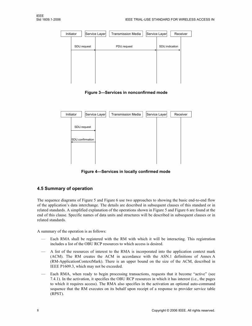
All services have four basic forms: request, indication, response, and confirmation. These services may beused in confirmed mode, nonconfirmed mode, and locally confirmed mode. Figure 2, Figure 3, and Figure 4illustrate the concepts.
InitiatorInitiator Service LayerService Layer Transmission Media ReceiverReceiverService LayerService Layer
SDU.request PDU.request SDU.indication
SDU.responsePDU.responseSDU.confirmation
Figure 2—Services in confirmed mode
Copyright © 2006 IEEE. All rights reserved. 7
IEEEStd 1609.1-2006 IEEE TRIAL-USE STANDARD FOR WIRELESS ACCESS IN
4.5 Summary of operation
The sequence diagrams of Figure 5 and Figure 6 use two approaches to showing the basic end-to-end flowof the application’s data interchange. The details are described in subsequent clauses of this standard or inrelated standards. A simplified explanation of the operations shown in Figure 5 and Figure 6 are found at theend of this clause. Specific names of data units and structures will be described in subsequent clauses or inrelated standards.
A summary of the operation is as follows:
— Each RMA shall be registered with the RM with which it will be interacting. This registrationincludes a list of the OBU RCP resources to which access is desired.
— A list of the resources of interest to the RMA is incorporated into the application context mark(ACM). The RM creates the ACM in accordance with the ASN.1 definitions of Annex A(RM-ApplicationContextMark). There is an upper bound on the size of the ACM, described inIEEE P1609.3, which may not be exceeded.
— Each RMA, when ready to begin processing transactions, requests that it become “active” (see7.4.1). In the activation, it specifies the OBU RCP resources in which it has interest (i.e., the pagesto which it requires access). The RMA also specifies in the activation an optional auto-commandsequence that the RM executes on its behalf upon receipt of a response to provider service table(RPST).
InitiatorInitiator Service LayerService Layer Transmission Media ReceiverReceiverService LayerService Layer
SDU.request PDU.request SDU.indication
Figure 3—Services in nonconfirmed mode
InitiatorInitiator Service LayerService Layer Transmission Media ReceiverReceiverService LayerService Layer
SDU.request
SDU.confirmation
Figure 4—Services in locally confirmed mode
8 Copyright © 2006 IEEE. All rights reserved.

IEEEVEHICULAR ENVIRONMENTS (WAVE)—RESOURCE MANAGER Std 1609.1-2006
— The RM and RCP (being WAVE applications) register with the WAVE management entity (WME)as specified in IEEE P1609.3. The RM registers so that it is incorporated into the application list sentin the provider service table (PST) that includes its ACM created above. The RCP on the OBUregisters with the WME as a user application.
— Upon receipt of a PST by the WME on the OBU, the RCP is notified that it is in the presence of anRM and receives, with the notification, access to the contents of the ACM.
— The RCP scans the ACM for a match on any resource that it hosts. If there is a match, it generates aRPST and, after requesting that the WME join the WAVE basic service set (WBSS, defined inIEEE P802.11p [B2] and IEEE P1609.3), transmits it directly to the provider RM.
— Upon receipt of this RPST, the RM notifies each associated RMA that it is in the presence of anOBU RCP hosting resources to which it has access, after the possible transmission of an auto-command sequence (see 7.4.1.3, 7.4.3.4, and 8.7) registered by the RMA.
— After this interchange is complete, the RMA, using the services of the RM, may request thatcommands be transmitted to the RCP using the exchange request service as specified in 7.5.1.
— As responses to these commands are received, the RM relays them in exchange responses to thecorrect RMA.
— The session is then formally terminated at the application level. The RMA terminates the session bytransmitting a Sleep Transaction command, described in 6.4.5, to the RCP and a terminate sessionindication, described in 7.4.5, to the RM on the RSU.
Figure 5—Data flow and management update operations in RMA/RM/RCP communication
Copyright © 2006 IEEE. All rights reserved. 9

IEEEStd 1609.1-2006 IEEE TRIAL-USE STANDARD FOR WIRELESS ACCESS IN
5. OBU resources
5.1 General
All OBUs will include memory in accordance with 5.2, but may also include additional resources such asUIs, equipment and network interfaces, and security devices. All resources provided shall be capable ofbeing controlled by the RCP using the commands defined in Clause 6.
5.2 Memory
WAVE devices conforming to this standard provide memory, subdivided into addressable blocks known aspages. These pages are used by RMAs to store (write) and retrieve (read) data using the RM command setdefined in Clause 6.
Pages in this standard are of the following types:
— Storage pages (general purpose read/write)
— Memory-mapped pages (e.g., UI)
— Transfer pages (to/from external interfaces)
Figure 6—Steps in establishing a data transfer session between RMA and RCP
10 Copyright © 2006 IEEE. All rights reserved.

IEEEVEHICULAR ENVIRONMENTS (WAVE)—RESOURCE MANAGER Std 1609.1-2006
When a page is reserved using the Reserve Memory command described in 6.4.6, the page type is specifiedby the enumerated value RM-PageType (defined in Annex A). Page types “storage” (type 0), “mapped”(type 1), and “transfer” (type 2) may use either an application-controlled format or the RM-Message formatdata structures. Page types “storageInsert” (type 128), “mappedInsert” (type 129), and “transferInsert”(type 130) shall use the RM-Message format data structure defined in 5.4.
Memory on the OBU that is accessible to RMAs shall have the following properties:
— It shall be capable of being subdivided into partitions (having the unique identifier “RM-partition” inAnnex A) and addressable pages within each partition (having the unique identifier “RM-Page” inAnnex A).
— The size in bytes of each partition shall be specified by a 16-bit integer (see 6.4.8), limiting them to64k bytes.
— The size in bytes of each page shall be specified by a 16-bit integer (see 6.4.6), limiting them to64k bytes. This size is further limited by the fact that several pages may be contained within a singlepartition.
— Page 0 in partition 0 shall be reserved for implementation-specific usage, and attempts to access itscontent shall be considered invalid.
— Partition 0 shall be mandatory, whereas the provision for defining other partitions is optional.
— An RMA may reserve, via an offline registration process, pages within the mandatory partition 0 or,if supported, a partition within which it may allocate pages used for its own specific purposes. Thisassures that each OBU that has been provisioned by any supplier acts as a virtual private device tomultiple RMAs. The current allocation of pages in partition 0, and partitions, is found in Annex B.
— Memory-mapped pages, if provided, shall have the capabilities described in 5.2.2.
— Transfer pages, if provided, shall have the capabilities described in 5.2.3.
All partitions and all pages are identified by a 16-bit identifier. The currently defined identifiers forpartitions and pages are provided in Annex B.
5.2.1 Storage pages
The most general type of page is the application-controlled storage page. A page of this type is used by anRMA to store and retrieve data. Usually, the implementor of an RMA requests that a population of OBUs bemanufactured within which their specific page is reserved. This may be done by the manufacturer, using theReserve Memory Page command, or at a facility operated by the implementor of the RMA. Subsequently,the RMA uses the services of the RM to store and retrieve data using its page. The data are stored in a formatspecific to the RMA and are not modified in any way by the RM or RCP.
5.2.2 Memory-mapped pages
The OBU may provide any combination of the UI devices described in this subclause. The availability ofthese devices accessible to an RMA shall be specified in a data field described in 8.5.2. If present, these UIdevices shall be controlled using the Set User Interface command specified in 6.4.4. UIs are controlled bywriting data to, or reading from, special memory pages referred to as memory-mapped pages. Thesememory-mapped pages act as buffers to the specific UI associated with each such page. The data written toone of these pages shall be used when a Set User Interface command (6.4.4) is given to transfer these data tothe associated UI. In the case of data coming from the UI, such as a keypad, the data written to this page maybe retrieved by a Read Memory Page command (6.4.1) to transfer these data to the RMA associated with thispage. Memory-mapped pages are preassigned the identities in Table B.1.
Copyright © 2006 IEEE. All rights reserved. 11

IEEEStd 1609.1-2006 IEEE TRIAL-USE STANDARD FOR WIRELESS ACCESS IN
5.2.3 Transfer pages
Pages designated as transfer pages may be provided as a means of interfacing with onboard equipment andnetworks. These pages shall be associated with a specific external interface controlled by the RCP if theinterface is present. If an authorized RMA writes data to one of these pages, the data shall be transferred tothe associated interface. The details of the transfer mechanism are implementation specific. The format ofthe data stored is defined when the specific application is designed. A means of storing data received frominterfaced onboard equipment or networks onto these transfer pages may be provided to create a two-waycommunication path to the RMA.
5.3 User interfaces (UIs)
5.3.1 Visual displays
The OBU may provide visual displays such as colored light emitting diodes (LEDs). There may be up tothree, with each being a different color. The acceptable colors are red, green, and yellow or their closestequivalent depending on the display technology.
5.3.2 Buzzers (audible alert)
The OBU may provide a buzzer used to alert the user with an audible signal.
5.3.3 Enunciators
The OBU may provide an enunciator. Enunciators are capable of simulating speech or music whereas abuzzer is limited to on/off fixed tones. The enunciator shall be used to present messages that have beenwritten to the corresponding memory-mapped page (see Note 5 and Note 6 in 6.4.4).
5.3.4 Character readout
The OBU may provide a character readout. The character readout shall be used to display text messages thathave been written to the corresponding memory-mapped page (see Note 5 and Note 6 in 6.4.4).
5.3.5 Keypad
The OBU may provide a keypad. The keystrokes that are entered using this keypad shall be inserted as amessage into the corresponding memory-mapped page. This page may then be read by authorizedapplications allowing them access to the data that were entered.
5.3.6 Future UI resources
Future revisions of this standard may provide for additional UI resources. The extensibility of the OBUConfiguration field (8.5.2) allows for the definition of bits that indicate the presence of new resources.
5.4 Data formats for memory resources
If interoperable applications are to share information with each other via the storage and retrieval of data, theformat and content of the data shall be defined by a standardized message format (the RMA message formatdefined in this subclause). When interoperability with other applications is not required, this standardpermits data to be in any format, including proprietary, and what is standardized is the means of storing andretrieving the data (see Clause 6).
12 Copyright © 2006 IEEE. All rights reserved.

IEEEVEHICULAR ENVIRONMENTS (WAVE)—RESOURCE MANAGER Std 1609.1-2006
Page types that support the Insert Message command defined in 6.4.3 shall make use of the RM-Messageformat. The RM-Message format enables the maintenance of lists of messages on these pages.
RM-Message format consists of a header and message contents following the ASN.1 description inAnnex A. Each message priority shall be in the range of 0 to 3 where messages of priority 0 are of highestpriority, or most urgent. (If the priority is specified as being from 4 to 255, it is treated as being priority 3).The assignment of message priorities is implemented through a registration mechanism outside the scope ofthis standard.
The Message Expiry field provides a means for the OBU RCP to remove messages that are no longer valid,by releasing the memory they occupy to be used to store newer messages. To extend the range of the expiryinterval, the Message Expiry field is interpreted as shown in Table 1. This format provides the option tospecify that messages expire in from 1 second to 192 days from the time of receipt of the message.
If there is not enough memory to store a new message on the requested page, the RCP shall delete the oldestmessage of lowest priority until there is sufficient memory to store the message. If this process fails, theerror response Insufficient Memory will be returned to the RMA, and the messages marked for deletion arerestored. The RCP shall never delete an unexpired message of the same or higher priority as the one that is tobe inserted. The onus is on the RMA to allocate enough memory for this type of page in the ReserveMemory Page command to accommodate all of the messages that it estimates will be required to existconcurrently on the page.
6. RM commands and responses
6.1 Overview
The RCP shall provide the capability to process the mandatory commands specified in this clause. Thesecommands reference memory partitions and pages that may be hosted by the OBU RCP.
All UIs, security devices, and onboard interfaces managed by the RM are mapped to a reserved page inpartition 0. As such, the management of these resources is reduced to the proper use of these commands tostore information on and retrieve information from these pages. Some of the commands described in thisclause are mandatory, and some are optional. For each command, there is a defined response. The responsesinclude values by which the RCP notifies the RMA that an optional command, although received, has notbeen implemented in this device.
Table 1—Message Expiry field
Value modifier Interpretation of values (0 to 64) for each “value modifier”
bit 7 6 5 4 3 2 1 0
0x00 Equal to the time in seconds message is valid 1 to 64 s 0 = 1 s, 63 = 64 s
0x01 Equal to the time in minutes message is valid 1 to 64 min 0 = 1 min, 63 = 64 min
0x02 Equal to the time in hours message is valid 1 h to 64 h 0 = 1 h, 63 = 64 h
0x03 Equal to the time in 3-day units message is valid 3 to 192 days 0 = 3 days, 63 = 192 days
Copyright © 2006 IEEE. All rights reserved. 13
IEEEStd 1609.1-2006 IEEE TRIAL-USE STANDARD FOR WIRELESS ACCESS IN
Throughout this standard, all multi-byte fields with numerical significance are to be encoded mostsignificant byte first and most significant bit (MSB) within each byte.
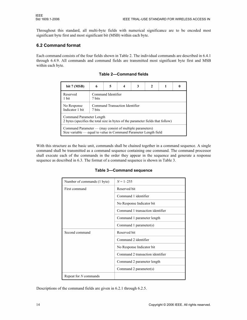
6.2 Command format
Each command consists of the four fields shown in Table 2. The individual commands are described in 6.4.1through 6.4.9. All commands and command fields are transmitted most significant byte first and MSBwithin each byte.
With this structure as the basic unit, commands shall be chained together in a command sequence. A singlecommand shall be transmitted as a command sequence containing one command. The command processorshall execute each of the commands in the order they appear in the sequence and generate a responsesequence as described in 6.3. The format of a command sequence is shown in Table 3.
Descriptions of the command fields are given in 6.2.1 through 6.2.5.
Table 2—Command fields
bit 7 (MSB) 6 5 4 3 2 1 0
Reserved1 bit
Command Identifier7 bits
No Response Indicator 1 bit
Command Transaction Identifier7 bits
Command Parameter Length2 bytes (specifies the total size in bytes of the parameter fields that follow)
Command Parameter — (may consist of multiple parameters)Size variable — equal to value in Command Parameter Length field
Table 3—Command sequence
Number of commands (1 byte) N = 1–255
First command Reserved bit
Command 1 identifier
No Response Indicator bit
Command 1 transaction identifier
Command 1 parameter length
Command 1 parameter(s)
Second command Reserved bit
Command 2 identifier
No Response Indicator bit
Command 2 transaction identifier
Command 2 parameter length
Command 2 parameter(s)
Repeat for N commands
14 Copyright © 2006 IEEE. All rights reserved.

IEEEVEHICULAR ENVIRONMENTS (WAVE)—RESOURCE MANAGER Std 1609.1-2006
6.2.1 Command Identifier field
Field size
The size of the Command Identifier field is 7 bits.
Usage
The Command Identifier field identifies the command to be executed and shall be identified by the codedcommand identifiers shown in Table 4. A full description of each command is found in 6.4.
Table 4—Command identifiers
Command identifier Command name Implementation requirements and usage
hex(00) Reserved Reserved for future assignment.
hex(01.. 0F) Available for new commands
Reserved for future assignment.
hex(10) Read Memory Page
Mandatory
Used to retrieve data previously stored on a page.
hex(11) Write Memory Page
Mandatory only if read/write memory is present
Used to store data on a page.
hex(12) Insert Message Mandatory only if read/write memory is present
Used to insert messages, in priority sequence, into the list on a page that supports message inserts.
hex(13.. 1F) Reserved Reserved for future assignment.
hex(20) Set User Interface Mandatory only if any UI is present
Used to control action of UI.
hex(21.. 2F) Reserved Reserved for future assignment.
hex(30) Sleep Transaction Mandatory
Used to signal a pause or end of transaction to the RCP.
hex(31.. 3F) Reserved
hex(40) Reserve Memory Page
Mandatory only if read/write memory is present
Used to create a new page in a specified partition.
hex(41) Release Memory Page
Mandatory only if Reserve Memory Page command is implemented
Used to remove a page and release its memory.
hex(42) Reserved
hex(43) Reserve Partition Optional
Used to create a new partition on the OBU. Partition 0 is mandatory and preallocated.
Copyright © 2006 IEEE. All rights reserved. 15

IEEEStd 1609.1-2006 IEEE TRIAL-USE STANDARD FOR WIRELESS ACCESS IN
6.2.2 No Response Indicator bit
Field size
The size of the No Response Indicator bit is 1 bit.
Usage
— If set to zero, the No Response Indicator bit shall indicate to the RCP that the appropriate response tothe transaction shall be returned.
— If set to one, the No Response Indicator bit shall indicate to the RCP that a response to this commandshall not be returned.
NOTE—It is normal to request a response to assure that the command was received and the action taken. A means ofsuppressing the response is provided but should be used with care.
6.2.3 Command Transaction Identifier field
Field size
The size of the Command Transaction Identifier field is 7 bits.
Usage
The Command Transaction Identifier field shall be set by the RMA for each command transmitted to anRCP as a means of uniquely identifying this instance of a command. This identifier shall be returnedunaltered in the response to that command. As such, the RMA can use this field in any manner that allows itto associate the response with the original command. For example, an incremental wraparound counter maybe used.
6.2.4 Command Parameter Length field
Field size
The size of the Command Parameter Length field is 2 bytes.
Usage
The Command Parameter Length field shall be used by the RMA to specify the total length (in bytes) of theCommand Parameter field that follows.
hex(44) Release Partition Mandatory only if Reserve Partition command is implemented
Used to remove a partition and release its memory.
hex(45..6F) Reserved
hex(70..7F) Available for manufacturer-specific testing
Optional
Shall not be used in production units deployed in the field.
Table 4—Command identifiers (continued)
Command identifier Command name Implementation requirements and usage
16 Copyright © 2006 IEEE. All rights reserved.

IEEEVEHICULAR ENVIRONMENTS (WAVE)—RESOURCE MANAGER Std 1609.1-2006
NOTE—The Command Parameter Length field allows the RCP to extract the parameters to the current command andthen move to the next command in the sequence.
6.2.5 Command Parameter field
Field size
The length of the Command Parameter field is dependent on the command and shall be equal to the valuespecified in the Command Parameter Length field.
Usage
The Command Parameter field shall be used by the RMA to pass the information required by the RCP toexecute the command.
6.3 Response format
The RCP processes commands within a sequence of commands up to the first command that is found to beinvalid. For each valid command up to the first invalid command, plus this first invalid command, the RCPgenerates a response if the No Response Indicator bit is 0. All commands after the first invalid command areignored.
The response to an individual command is formatted as shown in Table 5. If multiple commands are beingresponded to at the same time (as a sequence), this sequence of responses shall be formatted as in Table 3.
NOTE—Just as commands are received in command sequences, responses to command sequences are returned inresponse sequences. Each of the commands in the sequence is responded to if requested, but the responses need not bereturned in the same order as the commands were received. The RMA uses the Command Identifier and CommandTransaction Identifier pair to associate responses with specific commands.
Table 5—Response fields
bit 7 (MSB) 6 5 4 3 2 1 0
Reserved1 bit
Command Identifier7 bits
Unused1 bit
Command Transaction Identifier7 bits
Response Status1 byte
Response Length2 bytes (specified the total size in bytes of the response data that follow)
Response DataSize variable
Copyright © 2006 IEEE. All rights reserved. 17

IEEEStd 1609.1-2006 IEEE TRIAL-USE STANDARD FOR WIRELESS ACCESS IN
6.3.1 Command Identifier field
Field size
The size of the Command Identifier field is 7 bits.
Usage
The Command Identifier field shall contain the command identifier received in the original commandsequence.
Default value
None
6.3.2 Command Transaction Identifier field
Field size
The length of the Command Transaction Identifier field shall be 7 bits.
Usage
The Command Transaction Identifier field shall contain the command transaction identifier received in theoriginal command (see 6.2.3).
Default value
None
6.3.3 Response Status field
Field size
The length of the Response Status field shall be 1 byte.
Usage
The Response Status field shall contain a value indicating the status of command execution by the RCP (seeTable 6). If a command failure is encountered, the process may stop returning responses only up to thecommand in error.
Default value
None
Response Status definitions
Table 6 lists the valid values for the Response Status field and the interpretation of each. A response to acommand shall contain valid response data only when the Response Status field is set to Command Success.All other values shall indicate a failure condition.
18 Copyright © 2006 IEEE. All rights reserved.

IEEEVEHICULAR ENVIRONMENTS (WAVE)—RESOURCE MANAGER Std 1609.1-2006
6.3.4 Response Length field
Field size
The size of the Response Length field is 2 bytes if the response is to a Read Memory Page command. For allother commands, this field is not present.
Table 6—Response Status values
Response name Value Specification and description
Reserved hex(0) Reserved.
Command Success hex(1) Execution completed successfully.
Command Failed hex(2) The command failed due to some unspecified condition, such as a parameter error.
Command Not Recognized hex(3) The command identifier is invalid.
Command Not Supported hex(4) The command is not supported by the RCP.
Page Not Defined hex(5) The page identifier does not match a page hosted by the RCP.
Partition Not Defined hex(6) The partition identifier does not match a partition hosted by the RCP.
Device Error hex(7) A malfunction has occurred in the RCP hardware or software.
Memory Access Error hex(8) The requested memory could not be accessed due to an undefined internal error.
Page Length Mismatch hex(9) The length of the memory image is greater than the length of the referenced page.
Insufficient Memory hex(A) Available free memory is insufficient to perform the command.
Commands Not Executed hex(B) Due to internal memory limits, none of the command sequence was executed. Either the entire sequence is retransmitted or, due to encountering an invalid command in sequence, the processing was aborted.
Command Sequence Error hex(C) Unable to process command sequence due to sequence formatting error. (Typically the known parameter length is incorrect.)
Page Type Mismatch hex(D) Request to write data to a message page or request to insert a message on a page that does not support messages.
Page Already Exists hex(E) Trying to reserve a page that was previously reserved.
Partition Already Exists hex(F) Trying to reserve a partition that was previously reserved.
Unauthorized hex (10) Access was denied due to lack of proper authorization.
Write Error hex(11) Attempted write to a read-only page.
Nonexistent hex (12) Attempt to release a partition or page that does not exist.
Reserved hex(13.. AF) Reserved.
Vendor Area hex(BF.. FF) Available for vendor-specific failure conditions.
Copyright © 2006 IEEE. All rights reserved. 19

IEEEStd 1609.1-2006 IEEE TRIAL-USE STANDARD FOR WIRELESS ACCESS IN
Usage
The Response Length field shall specify the total length (in bytes) of the data contained in the ResponseData field.
Default value
None
6.3.5 Response Data field
Field size
For the current command set, the Response Data field shall appear only if it is a successful response to aRead Memory Page command. In this case, it is variable in length and defined by the value in the ResponseLength field.
Usage
If:The command is Read Memory Page and the response status is Command Success
The Response Data field contains the requested page image.
Default value
None
6.4 Command definitions
This subclause describes in detail the commands found in Table 4. For each command, the fields describedin Table 2 and specific to that command appear under the Command definition headers. Each command isused by an RMA to perform an action to which the RCP (if requested) returns a response.
All fields that contain a size are encoded as an unsigned integer value with the most significant bytetransmitted first.
6.4.1 Read Memory Page command
The Read Memory Page command is used to request that the memory image of the specified page bereturned in the response. The No Response Indicator bit shall not be set for this command.
Command definition
The Read Memory Page command shall contain the fields shown in Table 7.
20 Copyright © 2006 IEEE. All rights reserved.

IEEEVEHICULAR ENVIRONMENTS (WAVE)—RESOURCE MANAGER Std 1609.1-2006
RCP normal behaviors
If the partition and page are hosted by the RCP, the response shall consist of the following:— Response Status field set to Command Success— Response Length field set to the length of the Response Data field— Response Data field containing the part of the page’s memory image that was requested
RCP abnormal responses
If a response is requested and the RCP is unable to process the command, it shall return in the ResponseStatus field the appropriate value defined in Table 6.
6.4.2 Write Memory Page command
The Write Memory Page command is used to request that the specified page be overwritten with thememory image that appears in the parameter list.
Command definition
The Write Memory Page command shall contain the fields shown in Table 8.
Table 7—Read Memory Page command fields
Command field Length (bytes) Description
Command Identifier 1 hex(10)
Command Transaction Identifier 1 (RMA controlled)
Command Parameter Length 2 Value = 8Total length in bytes of the command parameter fields that follow
Partition Identifier 2 Partition that contains the page
Page Identifier 2 Page within the specified partition
Page Offset 2 Byte at which to start
Number 2 The number of bytes to return
Table 8—Write Memory Page command fields
Command field Length (bytes) Description
Command Identifier 1 hex(11)
Command Transaction Identifier 1 (RMA controlled)
Command Parameter Length 2 Total length of the command parameter fields that follow
Partition Identifier 2 Partition that contains the page
Page Identifier 2 Page within specified partition
Page Offset 2 Byte at which to start
Number 2 The number of bytes to write
Memory Imagea
aNote that the RF interface may not allow large data files, and such situations require fragmentation at the lower layers.
Variable The part of the image of the page to be written
Copyright © 2006 IEEE. All rights reserved. 21

IEEEStd 1609.1-2006 IEEE TRIAL-USE STANDARD FOR WIRELESS ACCESS IN
RCP normal behaviors
If the partition and page are hosted by the RCP, the section specified by the Page Offset field and Numberfield shall be completely overwritten with the memory image provided as parameter.
If this is a transfer page, then the local process for transferring these data to the local network/equipmentassociated with this page shall be notified. This is a locally unique process that is outside the scope of thisstandard.
If requested, the RCP shall return a response with the Response Status field set to Command Success.
RCP abnormal responses
If a response is requested and the RCP is unable to process the command, it shall return in the ResponseStatus field the appropriate value defined in Table 6.
6.4.3 Insert Message command
The Insert Message command is used to insert a message into a list of messages on a single page that hasbeen reserved to support the insert message function. Such a page may thus contain multiple messages ratherthan a single one as in a basic read/write memory page. See Table 9 for Insert Message command fields. TheInsert Message command shall not be used for pages other than RM-PageType “storageInsert” (type 128),“mappedInsert” (type 129), and “transferInsert” (type 130) pages.
Command definition
The Insert Message command shall contain the fields shown in Table 9.
RCP normal behaviors
If the partition and page are hosted by the RCP, the RCP shall insert the message image command parameterinto the list of messages on the page.
The RCP shall use the priority of the message and its expiry date to insert the message into the list ofmessages currently on the page, first ordered with respect to priority (highest priority first) and then, withineach priority, ordered with respect to expiry time (soonest to expire first). (See 7.4 for details.)
If requested, the RCP shall return a response with the Response Status field set to Command Success.
Table 9—Insert Message command fields
Command field Length (bytes) Description
Command Identifier 1 hex(12)
Command Transaction Identifier 1 (RMA controlled)
Command Parameter Length 2 Total length of the command parameter fields that follow
Partition Identifier 2 Partition that contains the page
Page Identifier 2 Page within specified partition
Message Image Variable The message to append to the page
22 Copyright © 2006 IEEE. All rights reserved.
IEEEVEHICULAR ENVIRONMENTS (WAVE)—RESOURCE MANAGER Std 1609.1-2006
RCP abnormal responses
If a response is requested and the RCP is unable to process the command, it shall return in the ResponseStatus field the appropriate value defined in Table 6.
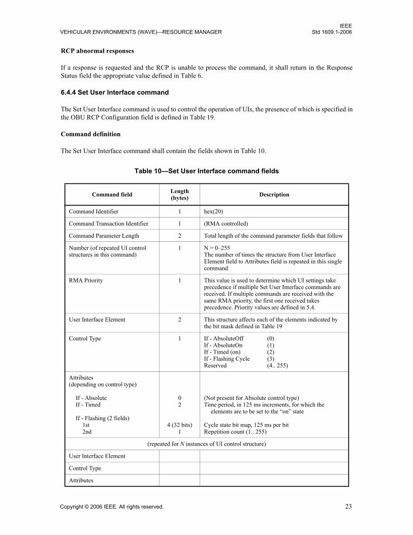
6.4.4 Set User Interface command
The Set User Interface command is used to control the operation of UIs, the presence of which is specified inthe OBU RCP Configuration field is defined in Table 19.
Command definition
The Set User Interface command shall contain the fields shown in Table 10.
Table 10—Set User Interface command fields
Command field Length (bytes) Description
Command Identifier 1 hex(20)
Command Transaction Identifier 1 (RMA controlled)
Command Parameter Length 2 Total length of the command parameter fields that follow
Number (of repeated UI control structures in this command)
1 N = 0–255The number of times the structure from User Interface Element field to Attributes field is repeated in this single command
RMA Priority 1 This value is used to determine which UI settings take precedence if multiple Set User Interface commands are received. If multiple commands are received with the same RMA priority, the first one received takes precedence. Priority values are defined in 5.4.
User Interface Element 2 This structure affects each of the elements indicated by the bit mask defined in Table 19
Control Type 1 If - AbsoluteOff (0)If - AbsoluteOn (1)If - Timed (on) (2)If - Flashing Cycle (3)Reserved (4.. 255)
Attributes(depending on control type)
If - AbsoluteIf - Timed
If - Flashing (2 fields)1st2nd
02
4 (32 bits)1
(Not present for Absolute control type)Time period, in 125 ms increments, for which the
elements are to be set to the “on” state
Cycle state bit map, 125 ms per bit Repetition count (1.. 255)
(repeated for N instances of UI control structure)
User Interface Element
Control Type
Attributes
Copyright © 2006 IEEE. All rights reserved. 23

IEEEStd 1609.1-2006 IEEE TRIAL-USE STANDARD FOR WIRELESS ACCESS IN
RCP normal behaviors
The RCP shall alter the specified UI elements, depending upon the value of the type and attributeparameters. The actions specified by the Control Type field and Attributes field are as follows:
— The AbsoluteOff control type shall turn the addressed UI element “off.” The “off” state shall bemaintained until changed by a subsequent command.
— The AbsoluteOn control type shall turn the addressed UI element “on.” The “on” state shall bemaintained until changed by a subsequent command.
— The Timed control type shall turn the addressed UI element “on” for a specified period of time andthen “off” until changed by a subsequent command. The time period shall be interpreted as thenumber of 125 ms increments.
— The Flashing control type shall cycle the state of the addressed UI element based upon a 4-byte(32 bit) bit map. A one indicates “on,” a zero “off.”— Each bit in the map shall represent an interval of 125 ms (thus the total bit map represents
32 × [1/8] s = 4 s).— The repetition byte shall indicate the number of times (0 to 255) the bit map cycle pattern shall
be performed.
NOTE—Following is an example of flashing parameters:
[11111111000000001111111100000000, 20] is interpreted as follows:1 s on, 1 s off, 1 s on, 1 s off, repeated 20 times. (Total 80 s of flashing at 1 Hz.)
The bits in the 32-bit sequence are processed from the left to right of the representation above.
The bits are received in the following byte order in the command:11111111 left-most bits of 32-bit sequence represented above: left-most bit processed first000000001111111100000000 right-most bits of 32-bit sequence represented above: left-most bit processed first
NOTE 1—An implementation that provides any colored display elements shall provide elements of colors as close tored, green, and yellow as possible for the given technology it uses.
NOTE 2—The RCP shall perform the action specified for each instance of the repeated control structure in the orderthey appear in the list.
NOTE 3—The completion of the specified UI control specifications shall not be affected by the reception of any othertransmissions from any RM except for those with overriding RMA priority.
NOTE 4—If two display elements are to be set independently, (e.g., green solid, yellow flashing), a single UI commandspecifying two separate UI control structures may be used.
NOTE 5—The control of the character readout UI and of the enunciator UI is performed with two separate commands.The commands may be received in the same command sequence. The first one is a Write Page command, specifying themessage to be displayed or enunciated, and the second one is a Set User Interface command, specifying that thecharacter readout or enunciator be activated as specified in the UI control structure.
NOTE 6—A page has been allocated for use by the Set User Interface command. Its identifier is hex(FF03), and it isdesignated for use as [UI image storage]. This page is provided for convenience, and it is used to store the last image ofthe controls that are in effect for each UI.
If requested, the RCP shall return a response with the Response Status field set to Command Success.
RCP abnormal responses
If a response is requested and the RCP is unable to process the command, it shall return in the ResponseStatus field the appropriate value defined in Table 6.
24 Copyright © 2006 IEEE. All rights reserved.

IEEEVEHICULAR ENVIRONMENTS (WAVE)—RESOURCE MANAGER Std 1609.1-2006
6.4.5 Sleep Transaction command
The Sleep Transaction command is used to inform the receiving OBU that either— The session is complete and no more commands will be sent in this communication session, or— The session is to be paused and resumed at a specified interval in the future.
Command definition
The Sleep Transaction command shall contain the fields shown in Table 11.
RCP normal behaviors
If the Pause Interval field value is zero, it indicates that the transaction is complete. This command uses theWME-Application.request services of IEEE P1609.3 to inform the WME that it is inactive.
If the Pause Interval field value is between zero and hex(FF), it is an indication to the RCP that it shalltemporarily stop transmitting data to the RM for the requested pause interval after it has returned theresponse to the command.
If the Pause Interval field value is hex(FF), the current pause shall be aborted.
The RCP is responsible for timing the interval and resuming the session.
If requested, the RCP shall return a response with the Response Status field set to Command Success.
RCP abnormal responses
If a response is requested and the RCP is unable to process the command, it shall return in the ResponseStatus field the appropriate value defined in Table 6.
Table 11—Sleep Transaction command fields
Command field Length (bytes) Description
Command Identifier 1 hex(30)
Command Transaction Identifier 1 (RMA controlled)
Command Parameter Length 2 Total length of the command parameter fields that follow (Value = hex(00 01) for this command)
Pause Interval 1 The time in 125 ms intervals that this application shall wait before resuming the session.Zero indicates that the session is complete.
Copyright © 2006 IEEE. All rights reserved. 25

IEEEStd 1609.1-2006 IEEE TRIAL-USE STANDARD FOR WIRELESS ACCESS IN
6.4.6 Reserve Memory Page command
The Reserve Memory Page command is used to allocate a page of memory from the free memory within aspecified partition. Such a reservation represents a permanent allocation until it has been released by aRelease Memory Page command.
NOTE—This command shall be transmitted alone, that is, in a sequence of 1 command. This assures a quiescent state isreached before any other commands that reference this page are processed.
Command definition
The Reserve Memory Page command shall contain the fields shown in Table 12.
RCP normal behaviors
If there is sufficient memory in the specified partition’s pool of available memory and the page has notpreviously been reserved, the RCP shall create the page within the partition.
If requested, the RCP shall return a response with the Response Status field set to Command Success.
RCP abnormal responses
If a response is requested and the RCP is unable to process the command, it shall return in the ResponseStatus field the appropriate value defined in Table 6.
6.4.7 Release Memory Page command
The Release Memory Page command is used to release the memory occupied by a page that had previouslybeen reserved to free memory within the specified partition.
Command definition
The Release Memory Page command shall contain the fields shown in Table 13.
Table 12—Reserve Memory Page command fields
Command field Length (bytes) Description
Command Identifier 1 hex(40)
Command Transaction Identifier 1 (RMA controlled)
Command Parameter Length 2 Total length of the command parameter fields that follow
Partition Identifier 2 Partition in which the page is to be reserved
Page Identifier 2 Identifier for the new page
Page Size 2 Length (in bytes) of this page
Page Type 1 ASN.1 type RM-PageType (see Annex A). This field specifies if the page type is storage, transfer, or memory-mapped and whether it is to support Insert Message command.
26 Copyright © 2006 IEEE. All rights reserved.

IEEEVEHICULAR ENVIRONMENTS (WAVE)—RESOURCE MANAGER Std 1609.1-2006
RCP normal behaviors
If the partition and page exist, the RCP shall release the memory occupied by the page to the partition’savailable memory.
If requested, the RCP shall return a response with the Response Status field set to Command Success.
RCP abnormal responses
If a response is requested and the RCP is unable to process the command, it shall return in the ResponseStatus field the appropriate value defined in Table 6.
6.4.8 Reserve Partition command
The Reserve Partition command is used to allocate a partition from the OBU’s available free memory. Sucha reservation represents a permanent allocation until it has been released by a Release Partition command.
NOTE—This command shall be transmitted alone, that is, in a sequence of 1 command. This assures a quiescent state isreached before any other commands that reference this page are processed.
Command definition
The Reserve Partition command shall contain the fields shown in Table 14.
Table 13—Release Memory Page command fields
Command field Length (bytes) Description
Command Identifier 1 hex(41)
Command Transaction Identifier 1 (RMA controlled)
Command Parameter Length 2 Total length of the command parameter fields that follow
Partition Identifier 2 Partition for this page
Page Identifier 2 Identifier for the page
Table 14—Reserve Partition command fields
Command field Length (bytes) Description
Command Identifier 1 hex(43)
Command Transaction Identifier 1 (RMA controlled)
Command Parameter Length 2 Total length of the command parameter fields that follow
Partition Identifier 2 Partition identifier to be used
Partition Size 2 Length (in bytes) of the requested partition
Copyright © 2006 IEEE. All rights reserved. 27

IEEEStd 1609.1-2006 IEEE TRIAL-USE STANDARD FOR WIRELESS ACCESS IN
RCP normal behaviors
If there is sufficient memory on the OBU’s pool of available memory and the partition does not currentlyexist, the RCP shall allocate the partition.
If requested, the RCP shall return a response with the Response Status field set to Command Success.
RCP abnormal responses
If a response is requested and the RCP is unable to process the command, it shall return in the ResponseStatus field the appropriate value defined in Table 6.
6.4.9 Release Partition command
The Release Partition command is used to release the memory occupied by a partition that had previouslybeen reserved to the OBU’s available free memory.
Command definition
The Release Partition command shall contain the fields shown in Table 15.
RCP normal behaviors
If the partition exists, the RCP shall return the memory it occupied to the OBU’s pool of available memory.
If requested, the RCP shall return a response with the Response Status field set to Command Success.
RCP abnormal responses
If a response is requested and the RCP is unable to process the command, it shall return in the ResponseStatus field the appropriate value defined in Table 6.
Table 15—Release Partition command fields
Command field Length (bytes) Description
Command Identifier 1 hex(44)
Command Transaction Identifier 1 (RMA controlled)
Command Parameter Length 2 Total length of the command parameter fields that follow
Partition Identifier 2 Partition identifier to be released
28 Copyright © 2006 IEEE. All rights reserved.

IEEEVEHICULAR ENVIRONMENTS (WAVE)—RESOURCE MANAGER Std 1609.1-2006
7. Services provided by the RM to the RMA
7.1 General
As stated, the WAVE RM, although implemented like any WAVE application, acts as an application layerthat provides services to WAVE RMAs to
— Activate and deactivate
— When active, make their presence known to OBUs that host RCP resources to which they haveaccess
— Exchange commands and responses with the WAVE RCP on OBUs that respond
— Terminate an existing data exchange session
As reference:
— The “services” used by the RM to make the presence of an RMA known are found in Clause 7.
— The “resources” that an RMA manages are found in Clause 5.
— The “commands” that an RMA uses to manage the resources and the required “responses” are foundin Clause 6.
The interface described in this clause is conducted by the interchange of APDUs described in this clausebetween RMAs and RM, typically over a secured Internet Protocol (IP) network. The flow of APDUsbetween RMAs and RM is depicted in Figure 5 (in 4.5).
NOTE 1—If conducted over an IP network, the activation request described in this clause would have to be addressed toa known UDP or Transmission Control Protocol (TCP) port. This port is currently not reserved.
NOTE 2—In some cases, an RMA may be co-resident with the RM in the provider device. In these cases, the protocolbetween the RMA and RM is not conducted over a network. Instead it is implemented across a SAP within the providerdevice. In these cases, it would make use of the ASDUs described for each service.
7.2 RMA-RM interface service elements
This subclause details the differences between APDU and ASDU.
Services are conducted by the exchange of requests and responses and by the exchange of indications andconfirmations. Data units that are transmitted as part of the protocol are known as protocol data units(PDUs), whereas data units exchanged across a software interface are known as service data units (SDUs).
7.2.1 PDUs—RMA APDU
WAVE RMA APDUs are interchanged between a remote RMA and the RM on the provider device via asecure network connection. Being transmitted over a “visible” interface, their format is formally describedby an ASN.1 type definition. The base ASN.1 type is RMA-APDU (defined in Annex A).
7.2.2 SDUs—RMA ASDU
SAPs are abstractions of an interface between implementation-specific software modules residing within adevice. They are described in a notation that resembles a software interface. In this clause, for each formaldefinition of an APDU, there exists a matching ASDU to be used if the RMA resides on the same device asthe RM.
Copyright © 2006 IEEE. All rights reserved. 29

IEEEStd 1609.1-2006 IEEE TRIAL-USE STANDARD FOR WIRELESS ACCESS IN
7.2.3 PDU and SDU naming convention
Each service is given a service name. Subsequently, “<service>” is to be replaced by the associated servicename. For example,
RMA-<SERVICE>-Request
represents an APDU described in ASN.1, transmitted over a “visible” interface to invoke a service, while
RMA-<service>.request
represents the associated ASDU, implemented internally, that is used to invoke the same service.
7.3 Protocol services
Protocol services are subdivided into— Management services, used to perform administration of the interface (see 7.4)— Data transfer services, used to exchange information across the communications link (see 7.5)
The ASN.1 type RMA-APDU specifies the APDUs that are provided. It consists of a choice of the serviceslisted in Table 16.
NOTE—In 7.4 and 7.5, the APDU types are found in Annex A.
Table 16—RMA-RM APDU
RMA-ACTIVATE-Request
RMA-ACTIVATE-Response
RMA-NOTIFY-Indication
RMA-NOTIFY-Confirmation
RMA-TERMINATESESSION-Indication
RMA-TERMINATESESSION-Confirmation
RMA-EXCHANGE-Request
RMA-EXCHANGE-Response
RMA-EXCHANGE-Confirmation
RMA-DEACTIVATE-Request
RMA-DEACTIVATE-Response
30 Copyright © 2006 IEEE. All rights reserved.
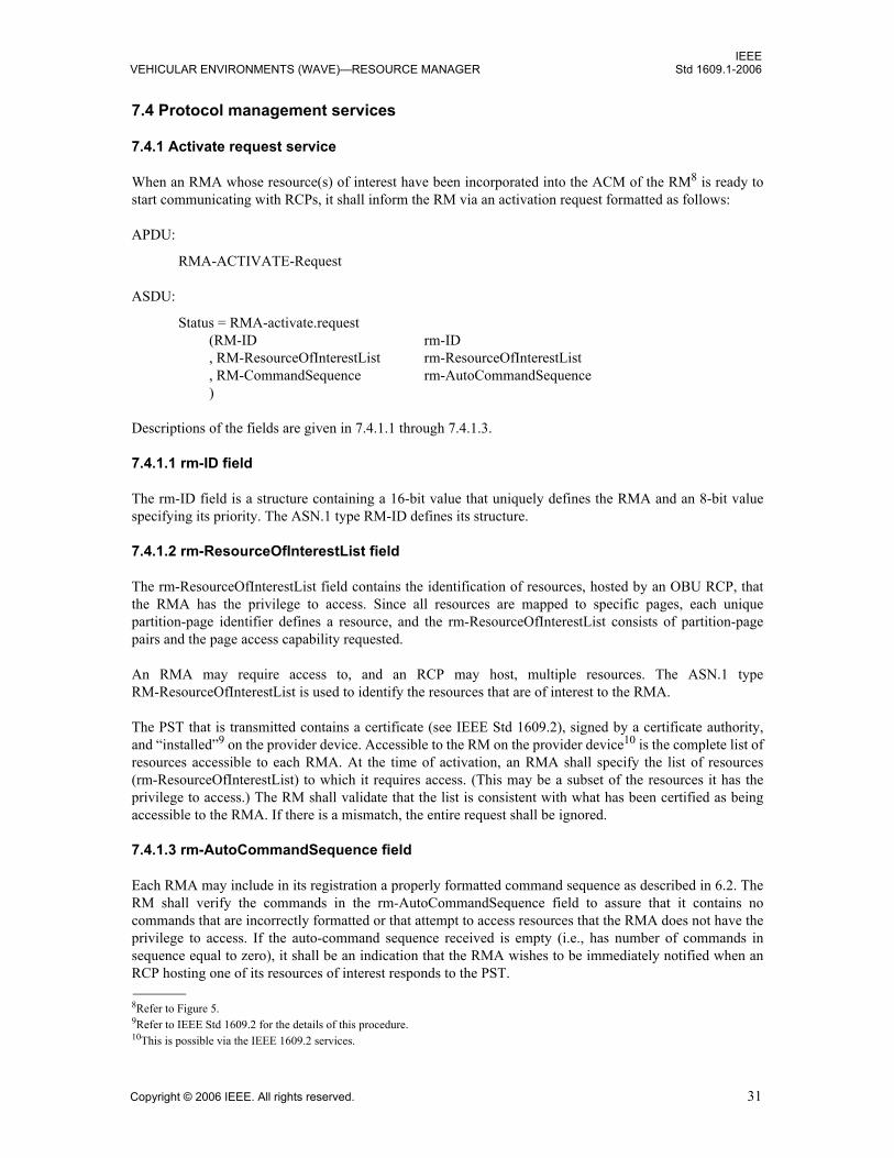
IEEEVEHICULAR ENVIRONMENTS (WAVE)—RESOURCE MANAGER Std 1609.1-2006
7.4 Protocol management services
7.4.1 Activate request service
When an RMA whose resource(s) of interest have been incorporated into the ACM of the RM8 is ready tostart communicating with RCPs, it shall inform the RM via an activation request formatted as follows:
APDU:
RMA-ACTIVATE-Request
ASDU:
Status = RMA-activate.request(RM-ID rm-ID, RM-ResourceOfInterestList rm-ResourceOfInterestList, RM-CommandSequence rm-AutoCommandSequence)
Descriptions of the fields are given in 7.4.1.1 through 7.4.1.3.
7.4.1.1 rm-ID field
The rm-ID field is a structure containing a 16-bit value that uniquely defines the RMA and an 8-bit valuespecifying its priority. The ASN.1 type RM-ID defines its structure.
7.4.1.2 rm-ResourceOfInterestList field
The rm-ResourceOfInterestList field contains the identification of resources, hosted by an OBU RCP, thatthe RMA has the privilege to access. Since all resources are mapped to specific pages, each uniquepartition-page identifier defines a resource, and the rm-ResourceOfInterestList consists of partition-pagepairs and the page access capability requested.
An RMA may require access to, and an RCP may host, multiple resources. The ASN.1 typeRM-ResourceOfInterestList is used to identify the resources that are of interest to the RMA.
The PST that is transmitted contains a certificate (see IEEE Std 1609.2), signed by a certificate authority,and “installed”9 on the provider device. Accessible to the RM on the provider device10 is the complete list ofresources accessible to each RMA. At the time of activation, an RMA shall specify the list of resources(rm-ResourceOfInterestList) to which it requires access. (This may be a subset of the resources it has theprivilege to access.) The RM shall validate that the list is consistent with what has been certified as beingaccessible to the RMA. If there is a mismatch, the entire request shall be ignored.
7.4.1.3 rm-AutoCommandSequence field
Each RMA may include in its registration a properly formatted command sequence as described in 6.2. TheRM shall verify the commands in the rm-AutoCommandSequence field to assure that it contains nocommands that are incorrectly formatted or that attempt to access resources that the RMA does not have theprivilege to access. If the auto-command sequence received is empty (i.e., has number of commands insequence equal to zero), it shall be an indication that the RMA wishes to be immediately notified when anRCP hosting one of its resources of interest responds to the PST.
8Refer to Figure 5.9Refer to IEEE Std 1609.2 for the details of this procedure.10This is possible via the IEEE 1609.2 services.
Copyright © 2006 IEEE. All rights reserved. 31

IEEEStd 1609.1-2006 IEEE TRIAL-USE STANDARD FOR WIRELESS ACCESS IN
NOTE—If an RCP responds to the PST indicating that it hosts resources of interest to multiple RMAs, although feasible,no attempt will be made to amalgamate the auto-command sequences from the multiple RMAs into a unified auto-command sequence. Instead, the RM will issue each auto-command sequence separately in the order of RMA priority or,if the RMAs are of the same priority, in an implementation-specific order.
7.4.2 Activate response service
To complete the activation process, a response to the activation shall be returned by the RM to the originatorof the request via an activation response formatted as follows:
APDU:
RMA-ACTIVATE-response
ASDU:
Status = RMA-activate.response(RM-ConnectionID rm-ConnectionID, RM-ActivationStatus rm-ActivationStatus)
Descriptions of the fields are given in 7.4.2.1 and 7.4.2.2.
7.4.2.1 rm-ConnectionID field
The rm-ConnectionID field value shall be assigned by the RM. Its usage is internal to the RM.
7.4.2.2 rm-ActivationStatus field
The rm-ActivationStatus field shall be used to return the status of the request. The only information returnedin the response will be an indication of success. If there is an error in the APDU, the request shall be ignored.If a valid response is lost in transmission, the RMA shall repeat the request and eventually receive theresponse with successful status.
7.4.3 Notify indication service
After an RMA has activated, it waits for notifications from the RM of potential communication partners.The notification service shall be provided as a means of indicating to an RMA that an OBU RCP hosting atleast one resource to which it has access has entered the provider device’s communication zone. The formatof this service is as follows:
APDU:
RMA-NOTIFY-Indication
ASDU:
RMA-notify.indication(RM-ConnectionID rm-ConnectionID, RM-LinkIdentifier rm-LinkID, RM-ResourceElementList rm-Resources, RM-ResponseSequence rm-AutoResponseSequence)
Descriptions of the fields are given in 7.4.3.1 through 7.4.3.4.
32 Copyright © 2006 IEEE. All rights reserved.

IEEEVEHICULAR ENVIRONMENTS (WAVE)—RESOURCE MANAGER Std 1609.1-2006
7.4.3.1 rm-ConnectionID field
The rm-ConnectionID field shall contain a copy of the value received in the RMA-ACTIVATE-Response.
7.4.3.2 rm-LinkID field
The rm-LinkID field, passed to the RMA, shall contain an internal value that is subsequently used by theRM on the provider device to identify the session just established. The RM shall use this value to identifyeach of the concurrent WAVE communication sessions, in all subsequent services.
7.4.3.3 rm-Resources field
The rm-Resources field shall contain a list of the resources that are hosted by the receiving OBU and ofinterest to the particular RMA.
NOTE—The RPST contains the complete list of resources hosted by the RCP that are of interest to all RMAs beingserviced by the RM. The RM shall reformat the list into sub-lists, each properly formatted into anRM-ResourceElementList, that pertain only to a particular RMA. These sub-lists are returned to their associated RMA inthe notify indication.
7.4.3.4 rm-AutoResponseSequence field
The rm-AutoResponseSequence field shall contain the sequence of responses to the auto-commandsequence received by the RM from the RCP.
7.4.4 Notify confirmation service
Upon receipt of an RMA-NOTIFY-Indication, the RMA shall confirm its receipt by returning anRMA-NOTIFY-Confirmation. The format of this service is as follows:
APDU:
RMA-NOTIFY-Confirmation
ASDU:
RMA-notify.confirmation(RM-ConnectionID rm-ConnectionID, RM-LinkIdentifier rm-LinkID)
Descriptions of the fields are given in 7.4.4.1 and 7.4.4.2.
7.4.4.1 rm-ConnectionID field
The rm-ConnectionID field shall contain a copy of the value received in the RMA-ACTIVATE-Response.
7.4.4.2 rm-LinkID field
The rm-LinkID field shall contain an internal value that is subsequently used by the RM on the providerdevice to identify the session just established. The RM shall use this value to identify each of the concurrentWAVE communication sessions in all subsequent services.
Copyright © 2006 IEEE. All rights reserved. 33
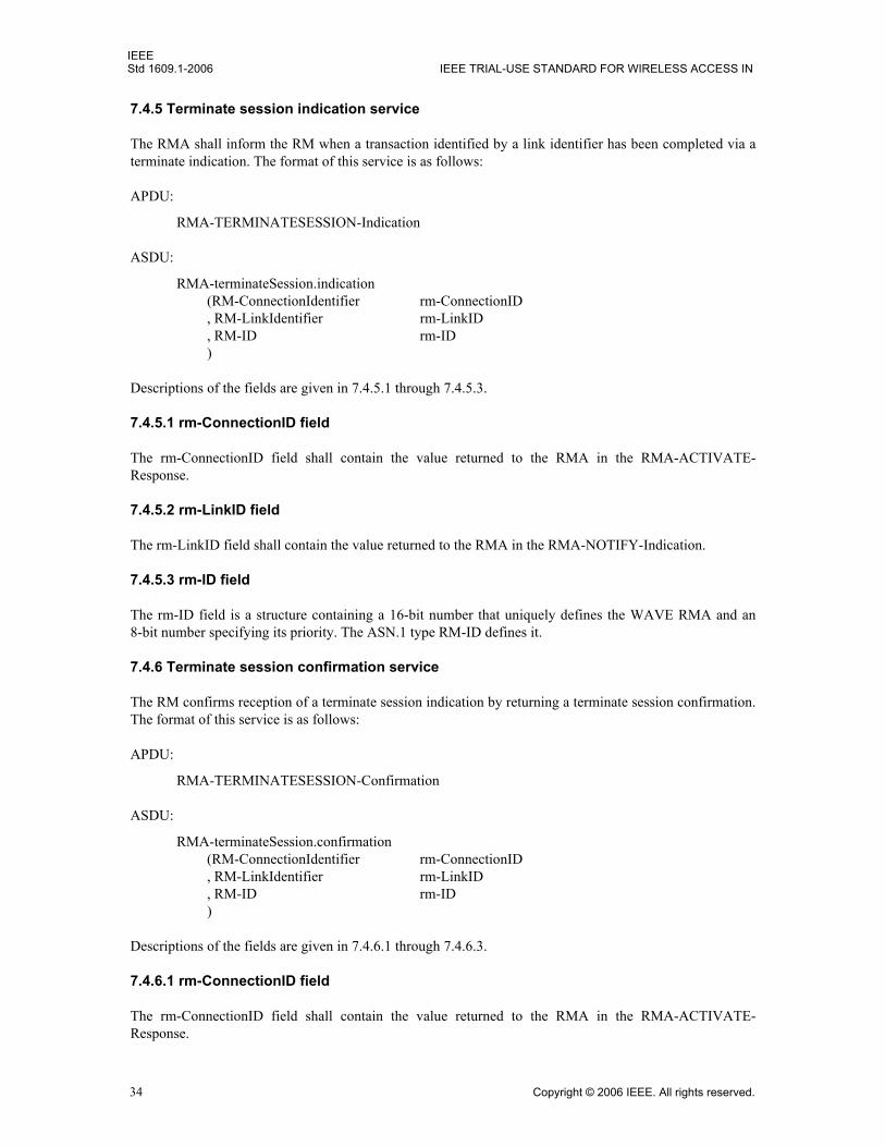
IEEEStd 1609.1-2006 IEEE TRIAL-USE STANDARD FOR WIRELESS ACCESS IN
7.4.5 Terminate session indication service
The RMA shall inform the RM when a transaction identified by a link identifier has been completed via aterminate indication. The format of this service is as follows:
APDU:
RMA-TERMINATESESSION-Indication
ASDU:
RMA-terminateSession.indication(RM-ConnectionIdentifier rm-ConnectionID, RM-LinkIdentifier rm-LinkID, RM-ID rm-ID)
Descriptions of the fields are given in 7.4.5.1 through 7.4.5.3.
7.4.5.1 rm-ConnectionID field
The rm-ConnectionID field shall contain the value returned to the RMA in the RMA-ACTIVATE-Response.
7.4.5.2 rm-LinkID field
The rm-LinkID field shall contain the value returned to the RMA in the RMA-NOTIFY-Indication.
7.4.5.3 rm-ID field
The rm-ID field is a structure containing a 16-bit number that uniquely defines the WAVE RMA and an8-bit number specifying its priority. The ASN.1 type RM-ID defines it.
7.4.6 Terminate session confirmation service
The RM confirms reception of a terminate session indication by returning a terminate session confirmation.The format of this service is as follows:
APDU:
RMA-TERMINATESESSION-Confirmation
ASDU:
RMA-terminateSession.confirmation(RM-ConnectionIdentifier rm-ConnectionID, RM-LinkIdentifier rm-LinkID , RM-ID rm-ID)
Descriptions of the fields are given in 7.4.6.1 through 7.4.6.3.
7.4.6.1 rm-ConnectionID field
The rm-ConnectionID field shall contain the value returned to the RMA in the RMA-ACTIVATE-Response.
34 Copyright © 2006 IEEE. All rights reserved.

IEEEVEHICULAR ENVIRONMENTS (WAVE)—RESOURCE MANAGER Std 1609.1-2006
7.4.6.2 rm-LinkID field
The rm-LinkID field shall contain the value returned to the RMA in the RMA-NOTIFY-Indication.
7.4.6.3 rm-ID field
The rm-ID field is a structure containing a 16-bit number that uniquely defines the WAVE RMA and an8-bit number specifying its priority. The ASN.1 type RM-ID defines it.
7.4.7 Deactivate request service
When the RMA wishes to stop operation for any reason, it shall inform the RM via a deactivate request. Theformat of this service is as follows:
APDU:
RMA-DEACTIVATE-Request
ASDU:
Status = RMA-deactivate.request(RM-ConnectionIdentifier rm-ConnectionID , RM-ID rm-ID)
NOTE—Deactivation is equivalent to a suspension of operation. To resume service, a new activation request is made.
Descriptions of the fields are given in 7.4.7.1 and 7.4.7.2.
7.4.7.1 rm-ConnectionID field
The rm-ConnectionID field shall contain the value returned to the RMA in the RMA-ACTIVATE-Response.
7.4.7.2 rm-ID field
The rm-ID field is a structure containing a 16-bit number that uniquely defines the WAVE RMA and an8-bit number specifying its priority. The ASN.1 type RM-ID defines it.
7.4.8 Deactivate response service
Upon receipt of a deactivate request from an RMA that is currently active, the RM shall return asconfirmation a deactivate response. The format of this service is as follows:
APDU:
RMA-DEACTIVATE-Response
ASDU:
Status = RMA-deactivate.request(RM-ActivationStatus rm-DeactivateStatus)
A description of the field is given in 7.4.8.1.
Copyright © 2006 IEEE. All rights reserved. 35

IEEEStd 1609.1-2006 IEEE TRIAL-USE STANDARD FOR WIRELESS ACCESS IN
7.4.8.1 rm-DeactivateStatus field
The rm-DeactivateStatus field shall be used to return the status of the request only if the RMA specified bythe rm-ID field is currently active. If there is in an error in the APDU, the request shall be ignored. If a validresponse is lost in transmission, the RMA shall repeat the request and eventually receive the response withsuccessful status.
7.5 Protocol data transfer services
After an application communication session has been established, the RMA may send RM commandsequences to the RCP. This shall be done using the exchange services.
7.5.1 Exchange request service
An RMA may send a command sequence to the RCP using the exchange request service. The format of thisservice is as follows:
APDU:
RMA-EXCHANGE-Request
ASDU:
RMA-exchange.request(RM-ConnectionIdentifier rm-ConnectionID, RM-LinkIdentifier rm-LinkID, RM-CommandSequence rm-CommandSequenceToSend)
Descriptions of the fields are given in 7.5.1.1 through 7.5.1.3.
7.5.1.1 rm-ConnectionID field
The rm-ConnectionID field shall contain the value returned to the RMA in the RMA-ACTIVATE-Response.
7.5.1.2 rm-LinkID field
The rm-LinkID field shall contain the value returned to the RMA in the RMA-NOTIFY-Indication.
7.5.1.3 rm-CommandSequenceToSend field
The rm-CommandSequenceToSend field shall contain a properly formatted command sequence to be sent tothe RCP on the OBU. Before transmission of this sequence to the RCP, the RM shall analyze this sequenceto assure that the RMA has the privilege to access the resources it addresses in this sequence and that thesyntax of each command is valid. If an error is encountered, the request is ignored.
7.5.2 Exchange response service
After a command sequence has been transmitted to the RCP and the response sequence has been received,the RM shall forward it to the RMA via an exchange response. The format of this service is as follows:
APDU:
RMA-EXCHANGE-Response
36 Copyright © 2006 IEEE. All rights reserved.

IEEEVEHICULAR ENVIRONMENTS (WAVE)—RESOURCE MANAGER Std 1609.1-2006
ASDU:
RMA-exchange.response(RM-ConnectionIdentifier rm-ConnectionID, RM-LinkIdentifier rm-LinkID, RM-ResponseSequence rm-ResponseSequenceReceived)
Descriptions of the fields are given in 7.5.2.1 through 7.5.2.3.
7.5.2.1 rm-ConnectionID field
The rm-ConnectionID field shall contain the value returned to the RMA in the RMA-ACTIVATE-Response.
7.5.2.2 rm-LinkID field
The rm-LinkID field shall contain the value returned to the RMA in the RMA-NOTIFY-Indication.
7.5.2.3 rm-ResponseSequenceReceived field
The rm-ResponseSequenceReceived field shall contain the sequence of responses to the commands returnedfrom the RCP.
7.5.3 Exchange confirmation service
After the RMA has received an exchange response from the RM, it shall confirm its reception by returningto the RM an exchange confirmation. The format of this service is as follows:
APDU:
RMA-EXCHANGE-Confirmation
ASDU:
RMA-exchange.confirmation(RM-ConnectionIdentifier rm-ConnectionID, RM-LinkIdentifier rm-LinkID)
Descriptions of the fields are given in 7.5.3.1 and 7.5.3.2.
7.5.3.1 rm-ConnectionID field
The rm-ConnectionID field shall contain the value returned to the RMA in the RMA-ACTIVATE-Response.
7.5.3.2 rm-LinkID field
The rm-LinkID field shall contain the value returned to the RMA in the RMA-NOTIFY-Indication.
Copyright © 2006 IEEE. All rights reserved. 37

IEEEStd 1609.1-2006 IEEE TRIAL-USE STANDARD FOR WIRELESS ACCESS IN
8. Interface to services used by RM
8.1 General
RM is implemented as a WAVE application that uses services provided by the— WME, as described in IEEE P1609.3— Security services, as described in IEEE Std 1609.2— UDP, as described in IETF RFC 768
This clause reviews the services of which an implementor of this standard makes use and provides a generaldescription of the interface to these services. The reader requires knowledge of the referenced standards.
NOTE—Throughout this clause, the phrase page of interest is considered synonymous with the term resource, and thetwo are used interchangeably.
8.2 OBU information not accessible using standard command set
Information not stored on registered pages is not accessible via the RM command set. Each OBU maycontain manufacturing information that is accessible only by a proprietary and secure mechanism. Storageformats and change/retrieval mechanisms of this type of information are not part of this standard.
8.3 Registration of RM and RCP
IEEE P1609.3 provides the WME-ApplicationRegistration.request service primitive: This service allows anapplication to register and thereby have its presence advertised to OBUs.
On the provider device, the RM registers as application class identifier (ACID) = "resource-manager" andprovides its ACM. The ACM contains a list of all the resources that are of interest to all of the currently“active” RMAs that have registered with the RM and, as a result, contains the access privileges of eachRMA.
The structure of the ACM is defined in Annex A as RM-ApplicationContextMark.
On the OBU, the RCP registers as ACID = "resource-manager". In the registration, it requests that the WMEpass the ACM to it for processing and wait for a request to join the WBSS to access the provider device.
8.4 WME notification to RCP
As described in IEEE P1609.3, when a match of the ACID is made by the WME on the OBU, the associatedapplication, in this case the RCP, is notified of the presence of the provider device and is passed theassociated ACM extracted from the PST. The RCP, from the contents of the ACM, then determines whetherit hosts any of the resources that appear in the RM-ResourceOfInterestList field (ASN.1 definition inAnnex A).
If there is any resource match, the RCP prepares an RPST as defined in 8.5.
8.5 OBU information returned in the response to PST by RCP
The following data are not accessible via the RM command set, but they shall be returned to the RM in theRPST (ASN.1 definition in Annex A). In turn, they shall be passed to the RMA by the RM.
38 Copyright © 2006 IEEE. All rights reserved.

IEEEVEHICULAR ENVIRONMENTS (WAVE)—RESOURCE MANAGER Std 1609.1-2006
The RPST structure contains the following:— The OBU RCP configuration information (Table 17)— A list of images of the requested pages of interest (a sequence of RM-ResourceElement defined in
Annex A) that are hosted by the OBU RCP and are to be returned in the RPST— A list of pages of interest (RM-ResourceList defined in Annex A) that are hosted by the OBU RCP
but not returned in the RPST
To create the RPST, the RCP, starting from the first entry in the resources of interest list, takes the followingactions:
— First, selects all of the page images that it hosts whose rm-PageAccess field specifies that they are tobe returned in the RPST and that fit into the maximum sized response packet, and creates the RM-ResourceElementList (ASN.1 definition in Annex A).
— Then, creates the rm-UnsentElements field, consisting of a list of pages that are not to be returned inthe RPST plus all of the pages that were to be returned but could not be fit into the maximum lengthresponse.
After creating the RPST, the RCP requests that the WME establish an infrastructure link with the providerdevice. IEEE P1609.3 provides the WME-Application.request service primitive for this purpose. When thelink is established, signaled by the reception of a WME-Notification.indication (defined in IEEE P1609.3),the RM-ResponseToPst structure is returned directly to the RM on the provider device using the UDPservices that are now available.
8.5.1 Memory Configuration field
The Memory Configuration field shall be used to indicate which read/write memory regions are present.Each bit shall indicate the presence or absence of a supported feature. Five bits are set aside for possiblefuture feature support. Values shall be interpreted as defined in Table 18.
Table 17—OBU information fields
Field name Specification and description
Memory Configuration Defines the availability of various memory regions.
OBU Configuration Defines the availability of various OBU peripherals, such as UI and enunciators. For future expansion, the OBU Configuration field is defined as an extensible field allowing for the definition of new resources.
Maximum Application Data Block Some devices may have a limitation on the maximum block of data they can handle received in an APDU. The RM is made aware of this limit via the value of this field.
Copyright © 2006 IEEE. All rights reserved. 39

IEEEStd 1609.1-2006 IEEE TRIAL-USE STANDARD FOR WIRELESS ACCESS IN
8.5.2 OBU Configuration field
The OBU Configuration field shall be used to indicate the configuration of installed UIs. Each bit indicatesthe presence or absence of a UI. The field is extensible by the use of bit 7 in each byte being set to 1 ifanother byte follows. The bits reserved for future use will be defined as new resources are standardized.
Table 18—Interpretation of Memory Configuration field
Location (bits) Interpretation (1 present, 0 not present)
7 (MSB) Multiple partition support
6 Commercial vehicle operations (CVO) file transfer page
5 Vehicle Information page
4 Reserved for future use
3 Reserved for future use
2 Reserved for future use
1 Reserved for future use
0 (LSB) Reserved for future use
Table 19—OBU Configuration field
Byte 1 - bitfields Interpretation
7 (MSB) Extensibility indicator = 0 if only 1 byte; 1 if byte 2 present
6 Red display element
5 Green display element
4 Yellow (or similar) display element
3 Character readout
2 Keypad
1 Buzzer
0 (LSB) Enunciator
Byte 2 - bitfields (if byte 2 present)
7 (MSB) extensibility indicator = 0 if only 2 bytes; 1 if byte 3 is present
6 Security Device (future)
5 Reserved for future use
4 Reserved for future use
3 Reserved for future use
2 Reserved for future use
1 Reserved for future use
7 (MSB) Reserved for future use
40 Copyright © 2006 IEEE. All rights reserved.

IEEEVEHICULAR ENVIRONMENTS (WAVE)—RESOURCE MANAGER Std 1609.1-2006
8.5.3 Maximum Application Data Block field
The Maximum Application Data Block field shall be used to indicate to the RM and the RMA the maximumsize of the data portion of commands sent to the RCP. This information is necessary when large pages aredefined on an OBU and the OBU has limited internal buffering space. A mechanism is provided in thecommand set to set up an end-to-end fragmentation scheme. (This mechanism is addressed in 6.4.1 and 6.4.2via the Page Offset field and Number field.)
A 16-bit integer is used to specify the value, allowing values from 0 to 65 535 bytes. The provider sets thevalue to the minimum of what it and the user can accommodate.
8.6 Reception of RPST by RM
At the provider device, the reception of the RM-ResponseToPst (ASN.1 definition in Annex A) by the RMis the RM’s notification that an OBU has entered the communication zone and that it hosts at least one pageof interest (resource) that at least one of the RMAs has registered as being of interest. The RM shall firstdetermine which of the RMAs that it will notify.
The received RM-ResourceElementList (ASN.1 definition in Annex A) contains pages of interest for all ofthe RMAs. The RM shall associate each page image (or indication of the presence of a page) it receives withits corresponding RMA. Then, for each RMA, it shall create a sub-list formatted as anRM-ResourceElementList and return it to the correct RMA via the RMA-NOTIFY-Indication servicedefined in 7.4.3.
8.7 Auto-command sequence processing
Before sending the RMA-NOTIFY-Indication to the RMA, the RM transmits to the RCP, if present, theoptional auto-command sequence that was registered by each RMA. As the UDP link has been established,the auto-command sequences (one for each RMA receiving a resource match) are sent to the UDP portassociated with the RCP. This is done in the order of highest priority to lowest priority RMA. If the prioritiesare the same, the order is implementation specific. (See 6.2 and 6.3 for the structure of command andresponse sequences.)
The RCP, upon receipt of the auto-command sequence, executes the commands received and returns to theRM the auto-command response sequence.
The RM then forwards the response sequence and the RM-ResourceElementList to the associated RMAusing the RMA-NOTIFY-Indication service. The receipt of this notification indicates to the RMA that anOBU to which it has requested access is in the WAVE communication zone.
8.8 Conducting an application session
If required, an application session may then be conducted between the RMA and RCP with the RM acting asa command validator and forwarding agent. The RMA constructs command sequences that it sends to theRM using the RMA-EXCHANGE-Request service defined in 7.5.1.
The RM, upon receipt of the RMA-EXCHANGE-Request, extracts the rm-SendCommandSequence andtransmits it to the RCP on the associated OBU. This is done after the command sequence is analyzed by theRM to assure that the syntax of each command is valid and that no command requests access to resourcesthat the RMA does not have privilege to access. If a violation is found, the request is ignored.
Copyright © 2006 IEEE. All rights reserved. 41

IEEEStd 1609.1-2006 IEEE TRIAL-USE STANDARD FOR WIRELESS ACCESS IN
Upon receipt of the command sequence, the RCP on the OBU executes the commands and returns to the RMthe associated response sequence.
Upon receipt of the packet from the RCP, the RM extracts the response sequence and forms therm-ReturnResponseSequence, which it transmits to the associated RMA using the RMA-EXCHANGE-Response service defined in 7.5.2.
8.9 Termination of application session
When the RMA decides that the session is complete, it transmits a Sleep Transaction command to the RCP.Upon receipt of the response to this command, or if no response is received in the timeout period, the RMAinforms the RM that the session is complete using the RMA-TERMINATESESSION-Indication service.
The RM confirms receipt of the indication with a corresponding confirmation and internally clears itsinternal resources.
42 Copyright © 2006 IEEE. All rights reserved.

IEEEVEHICULAR ENVIRONMENTS (WAVE)—RESOURCE MANAGER Std 1609.1-2006
Annex A
(normative)
ASN.1 encoding
IEEE-1609-1 DEFINITIONS::=
BEGIN
-- ==========================================================RMA-APDU::= CHOICE { rma-activate-request [0] RMA-ACTIVATE-Request, rma-activate-response [1] RMA-ACTIVATE-Response, rma-notify-indication [2] RMA-NOTIFY-Indication, rma-notify-confirmation [3] RMA-NOTIFY-Confirmation, rma-terminateSession-indication [4] RMA-TERMINATESESSION-Indication, rma-terminateSession-confirmation [5] RMA-TERMINATESESSION- Confirmation, rma-exchange-request [6] RMA-EXCHANGE-Request, rma-exchange-response [7] RMA-EXCHANGE-Response, rma-deactivate-request [8] RMA-DEACTIVATE-Request, rma-deactivate-response [9] RMA-DEACTIVATE-Response, rma-force-alignment [255] NULL}
RMA-ACTIVATE-Request::= SEQUENCE{rm-ID RM-ID, rm-ResourceList RM-ResourceList, rm-AutoCommandSequence RM-CommandSequence}
RMA-ACTIVATE-Response::= SEQUENCE{rm-ConnectionID RM-ConnectionIdentifier, rm-ActivationStatus RM-ActivationStatus}
RMA-DEACTIVATE-Request::= SEQUENCE{rm-ConnectionID RM-ConnectionIdentifier, rm-ID RM-ID}
RMA-DEACTIVATE-Response::= RM-ActivationStatus
RMA-EXCHANGE-Request::= SEQUENCE{rm-ConnectionID RM-ConnectionIdentifier, rm-LinkID RM-LinkIdentifier, rm-SendCommandSequence RM-CommandSequence}
Copyright © 2006 IEEE. All rights reserved. 43

IEEEStd 1609.1-2006 IEEE TRIAL-USE STANDARD FOR WIRELESS ACCESS IN
RMA-EXCHANGE-Response::= SEQUENCE{rm-ConnectionID RM-ConnectionIdentifier, rm-LinkID RM-LinkIdentifier, rm-ReturnResponseSequence RM-ResponseSequence}
RMA-EXCHANGE-Confirmation::= SEQUENCE{rm-ConnectionID RM-ConnectionIdentifier, rm-LinkID RM-LinkIdentifier}
RMA-NOTIFY-Confirmation::= SEQUENCE{rm-ConnectionID RM-ConnectionIdentifier, rm-LinkID RM-LinkIdentifier}
RMA-NOTIFY-Indication::= SEQUENCE{rm-ConnectionID RM-ConnectionIdentifier, rm-LinkID RM-LinkIdentifier, rm-Resources RM-ResourceElementList, rm-AutoResponseSequence RM-ResponseSequence}
RMA-TERMINATESESSION-Confirmation::= SEQUENCE{rm-ConnectionID RM-ConnectionIdentifier, rm-LinkID RM-LinkIdentifier, rm-ID RM-ID}
RMA-TERMINATESESSION-Indication::= SEQUENCE{rm-ConnectionID RM-ConnectionIdentifier, rm-LinkID RM-LinkIdentifier, rm-ID RM-ID}
RM-ActivationStatus::= INTEGER{rm-Success (0), rm-Fill (255) }(0..255)
RM-ApplicationContextMark::= RM-ResourceOfInterestList
RM-CommandSequence::= OCTET STRING
RM-ConnectionIdentifier::= INTEGER(0..65535)--Range:[0-2^16-1]
RM-ID::= SEQUENCE{rm-AppID INTEGER(0..65535), rm-AppPriority INTEGER(0..255)}
44 Copyright © 2006 IEEE. All rights reserved.
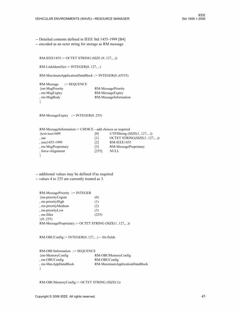
IEEEVEHICULAR ENVIRONMENTS (WAVE)—RESOURCE MANAGER Std 1609.1-2006
-- Detailed contents defined in IEEE Std 1455-1999 [B4]-- encoded as an octet string for storage as RM message
RM-IEEE1455::= OCTET STRING (SIZE (0..127,...))
RM-LinkIdentifier::= INTEGER(0..127,...)
RM-MaximumApplicationDataBlock ::= INTEGER(0..65535)
RM-Message ::= SEQUENCE{rm-MsgPriority RM-MessagePriority, rm-MsgExpiry RM-MessageExpiry, rm-MsgBody RM-MessageInformation}
RM-MessageExpiry ::= INTEGER(0..255)
RM-MessageInformation::= CHOICE --add choices as required{text-ieee1609 [0] UTF8String (SIZE(1..127,...)), sae [1] OCTET STRING(SIZE(1..127,...)), ieee1455-1999 [2] RM-IEEE1455, rm-MsgProprietary [3] RM-MessageProprietary, force-Alignment [255] NULL}
-- additional values may be defined if/as required-- values 4 to 255 are currently treated as 3.
RM-MessagePriority ::= INTEGER{rm-priorityUrgent (0), rm-priorityHigh (1), rm-priorityMedium (2), rm-priorityLow (3), rm-filler (255)}(0..255)RM-MessageProprietary::= OCTET STRING (SIZE(1..127,...))
RM-OBUConfig::= INTEGER(0..127,...) -- bit-fields
RM-OBUInformation ::= SEQUENCE{rm-MemoryConfig RM-OBUMemoryConfig, rm-OBUConfig RM-OBUConfig, rm-MaxAppDataBlock RM-MaximumApplicationDataBlock}
RM-OBUMemoryConfig::= OCTET STRING (SIZE(1))
Copyright © 2006 IEEE. All rights reserved. 45

IEEEStd 1609.1-2006 IEEE TRIAL-USE STANDARD FOR WIRELESS ACCESS IN
RM-Page::= INTEGER(0..65535)
RM-PageAccess ::= INTEGER{readWrite (0), readOnly (1),rwReturnInRPST (2) -- a readWrite page,roReturnInRPST (3) -- a readOnly page, fill (255)}(0..255)
RM-partition::= INTEGER(0..65535)
RM-PageType ::= INTEGER{storage (0), storageInsert (128), mapped (1), mappedInsert (129), transfer (2), transferInsert (130), fill (255)}(0..255)
RM-ResourceElement ::= SEQUENCE{rm-ResourceID RM-ResourceID, rm-ResourceImage OCTET STRING (SIZE(0..65535))}RM-ResourceID ::= SEQUENCE{rm-partition RM-partition, rm-Page RM-Page} RM-ResourceOfInterest::= SEQUENCE{rm-ResourceID RM-ResourceID, rm-PageAccess RM-PageAccess}
RM-ResourceOfInterestList::= SEQUENCE(SIZE(0..127,...)) OF RM-ResourceOfInterest
RM-ResourceElementList::=SEQUENCE{rm-OBUInformation RM-OBUInformation, rm-Elements SEQUENCE(SIZE(0..7,...))
OF RM-ResourceElement, rm-UnsentElements RM-ResourceList}
RM-ResourceList::= SEQUENCE(SIZE(0..31,...)) OF RM-ResourceID
RM-ResponseSequence::= OCTET STRING
46 Copyright © 2006 IEEE. All rights reserved.

IEEEVEHICULAR ENVIRONMENTS (WAVE)—RESOURCE MANAGER Std 1609.1-2006
RM-ResponseToPst ::= RM-ResourceElementList
-- ==========================================================
END -- of IEEE-1609-1 DEFINITIONS
Copyright © 2006 IEEE. All rights reserved. 47

IEEEStd 1609.1-2006 IEEE TRIAL-USE STANDARD FOR WIRELESS ACCESS IN
Annex B
(normative)
Registered pages and partitions
The partitions and pages in Table B.1 and Table B.2 have been registered.
Table B.1—Registered page identifiers for partition 0
Page number Page designation
hex(0.. 00FF) Reserved
hex(0100) California Department of Transportation
hex(0101) Onboard vehicle network - SAE J1708 [B5]formerly reserved by IEEE Std 1455™-1999 [B4]
hex(0102) Onboard vehicle network - SAE J1939 [B6]formerly reserved by IEEE Std 1455-1999 [B4]
hex(0103.. EFFF) Available for registration
hex(F000.. FEFF) Available for device testing before registration
Interface pages
hex(FF00) Keypad
hex(FF01) Enunciator
hex(FF02) Character readout
hex(FF03) UI image storage
hex(FF04..FFF0) Reserved by IEEE for future use
hex(FFF1) Onboard vehicle network - SAE J1708 [B5]
hex(FFF2) Onboard vehicle network - SAE J1939 [B6]
hex(FFF3.. FFFD) Reserved by IEEE for future use
hex(FFFE) Vehicle Information page
hex(FFFF) File Transfer page (CVO)
48 Copyright © 2006 IEEE. All rights reserved.
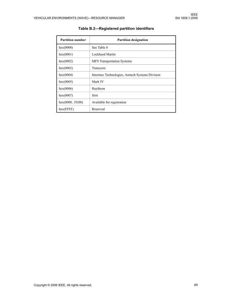
IEEEVEHICULAR ENVIRONMENTS (WAVE)—RESOURCE MANAGER Std 1609.1-2006
Table B.2—Registered partition identifiers
Partition number Partition designation
hex(0000) See Table 8
hex(0001) Lockheed Martin
hex(0002) MFS Transportation Systems
hex(0003) Transcore
hex(0004) Intermec Technologies, Amtech Systems Division
hex(0005) Mark IV
hex(0006) Raytheon
hex(0007) Sirit
hex(0008.. FE00) Available for registration
hex(FFFF) Reserved
Copyright © 2006 IEEE. All rights reserved. 49
IEEEStd 1609.1-2006 IEEE TRIAL-USE STANDARD FOR WIRELESS ACCESS IN
Annex C
(normative)
Protocol Implementation Conformance Statement (PICS) proforma11
C.1 General
The supplier of a protocol implementation that is claimed to conform to IEEE Std 1609.1 shall complete thefollowing protocol implementation conformance statement (PICS) proforma.
A completed PICS proforma is the PICS for the implementation in question. The PICS is a statement ofwhich capabilities and options of the protocol have been implemented. The PICS can have a number of uses,including use
a) By the protocol implementor, as a checklist to reduce the risk of failure to conform to the standardthrough oversight;
b) By the supplier and acquirer, or potential acquirer, of the implementation, as a detailed indication ofthe capabilities of the implementation, stated relative to the common basis for understandingprovided by the standard PICS proforma;
c) By the user, or potential user, of the implementation, as a basis for initially checking the possibilityof interworking with another implementation (note that, while interworking can never beguaranteed, failure to interwork can often be predicted from incompatible PICS proformas);
d) By a protocol tester, as the basis for selecting appropriate tests against which to assess the claim forconformance of the implementation.
C.2 Abbreviations and special symbols
C.2.1 Symbols for Status column
M mandatoryO optionalO.<n> optional, but support of at least one of the group of options labeled by the same <n> is requiredpred: conditional symbol, including predicate identification
C.3 Instructions for completing the PICS proforma
C.3.1 General structure of the PICS proforma
The first parts of the PICS proforma, Implementation identification and Protocol summary, are to becompleted as indicated with the information necessary to identify fully both the supplier and theimplementation.
11Copyright release for PICS proformas: Users of this standard may freely reproduce the PICS proforma in this annex so that it can beused for its intended purpose and may further publish the completed PICS.
50 Copyright © 2006 IEEE. All rights reserved.

IEEEVEHICULAR ENVIRONMENTS (WAVE)—RESOURCE MANAGER Std 1609.1-2006
The main part of the PICS proforma is a fixed questionnaire, divided into parts, each containing a number ofindividual items. Answers to the questionnaire items are to be provided in the rightmost column, either bysimply marking an answer to indicate a restricted choice (usually Yes or No) or by entering a value or a setor a range of values.12
Each item is identified by an item reference in the first column. The second column contains the question tobe answered. The third column contains the reference or references to the material that specifies the item inthe main body of this standard. The remaining columns record the status of each item, i.e., whether supportis mandatory, optional, or conditional, and provide the space for the answers (see also C.3.4). Marking anitem as supported is to be interpreted as a statement that all relevant requirements of the subclauses andnormative annexes, cited in the References column for the item, are met by the implementation.
A supplier may also provide, or be required to provide, further information, categorized as either additionalinformation or exception information. When present, each kind of further information is to be provided in afurther subclause of items labeled A<I> or X<I>, respectively, for cross-referencing purposes, where <I> isany unambiguous identification for the item (e.g., simply a numeral). There are no other restrictions on itsformat or presentation.
The PICS proforma for an implementation consists of C.4.1 through C.4.4 corresponding to the networkservices implemented.
A completed PICS proforma, including any additional information and exception information, is the PICSfor the implementation in question.13
C.3.2 Additional information
Items of additional information allow a supplier to provide further information intended to assist in theinterpretation of the PICS. It is not intended or expected that a large quantity of information will be supplied,and a PICS can be considered complete without any such information. Examples of such additionalinformation might be an outline of the ways in which an (single) implementation can be set up to operate ina variety of environments and configurations or information about aspects of the implementation that areoutside the scope of this standard but have a bearing upon the answers to some items.
References to items of additional information may be entered next to any answer in the questionnaire andmay be included in items of exception information.
C.3.3 Exception information
It may happen occasionally that a supplier will wish to answer an item with mandatory status (after anyconditions have been applied) in a way that conflicts with the indicated requirement. No preprinted answerwill be found in the Support column for this. Instead, the supplier shall write the missing answer into theSupport column, together with an X<I> reference to an item of exception information, and shall provide theappropriate rationale in the exception information item itself.
An implementation for which an exception information item is required in this way does not conform to thisstandard.14
12Note that there are some items where two or more choices from a set of possible answers may apply. All relevant choices are to bemarked in these cases.13Where an implementation is capable of being configured in more than one way, a single PICS may be able to describe all suchconfigurations. However, the supplier has the choice of providing more than one PICS, each covering some subset of theimplementation’s capabilities, if this makes for easier and clearer presentation of the information.14A possible reason for the situation described above is that a defect in this standard has been reported, a correction for which isexpected to change the requirement not met by the implementation.
Copyright © 2006 IEEE. All rights reserved. 51

IEEEStd 1609.1-2006 IEEE TRIAL-USE STANDARD FOR WIRELESS ACCESS IN
C.3.4 Conditional status
The PICS proforma contains a number of conditional items. These are items for which both the applicabilityof the item itself, and its status if it does apply (mandatory or optional), are dependent upon whether certainother items are supported.
Where a group of items is subject to the same condition for applicability, a separate preliminary questionabout the condition appears at the head of the group, with an instruction to skip to a later point in thequestionnaire if the N/A answer is selected. Otherwise, individual conditional items are indicated by aconditional symbol in the Status column.
A conditional symbol is of the form <pred>:<N>, where <pred> is a predicate as described below, and <N>is one of the status symbols M or O.
If the value of the predicate is true, the conditional item is applicable, and its status is given by S, the supportcolumn is to be completed in the usual way. Otherwise, the conditional item is not relevant, and the N/Aanswer is to be marked.
A predicate is one of the following:
a) An item-reference for an item in the PICS proforma: The value of the predicate is true if the item ismarked as supported, and the value is false otherwise.
b) A boolean expression constructed by combining item-references using the boolean operator OR:The value of the predicate is true if one or more of the items is marked as supported, and the value isfalse otherwise.
Each item referenced in a predicate, or in a preliminary question for grouped conditional items, is indicatedby an asterisk in the Item column.
C.4 PICS proforma—IEEE Std 1609.1
C.4.1 Implementation identification
NOTE 1—Only the first three items are required for all implementations. Other information may be completed asappropriate in meeting the requirement for full identification.
NOTE 2—The terms name and version should be interpreted appropriately to correspond with a supplier’s terminology(e.g., type, series, model).
Supplier
Contact point for queries about the PICS
Implementation name(s) and version(s)
Other information necessary for full identification, e.g., name(s) and version(s) of the machines and/or operating systems(s), system names
52 Copyright © 2006 IEEE. All rights reserved.

IEEEVEHICULAR ENVIRONMENTS (WAVE)—RESOURCE MANAGER Std 1609.1-2006
C.4.2 Protocol summary
C.4.3 Top-level architecture
C.4.4 Normative section:
Identification of protocol standard IEEE Std 1609.1 Clause 6
Identification of amendments and corrigenda to this PICS proforma that have been completed as part of this PICS
Amd. : Corr. :Amd. : Corr. :
Have any exception items been required? (See C.3.3; the answer Yes means that the implementation does not conform to IEEE Std 1609.1)
Yes No Yes No
Date of statement (dd/mm/yy)
Item OBU resources memory/UIs Reference Status Conformance
S1 Device functionality 4.1 M RSU OBU
S2 RMA accessible Read/Write memory provided 4.1, 5.2 O Yes No
S3 UIs included 4.1, 5.2 O Yes No
S4 Specialized interfaces via transfer pages exist 4.1, 5.2 O Yes No
S5 Vehicle Security devices provided 4.1 O Yes No
S6 Size of read/write memory provided for pool of partitions and pages
4.1 S2:M Kbytes:_____
S7 Partition 0 supported 5.2 M Yes No
S8 Partition 0 page 0 reserved and access attempts treated as invalid
5.2 M Yes No
S9 Memory partitions (other than 0) supported 5.2 O Yes No
S10 Storage pages supported Clause 5, 5.2, 5.2.1 S2:M Yes No
S11 Memory-mapped pages supported Clause 5, 5.2, 5.2.2 S3:M Yes No
S12 Transfer pages supported Clause 5, 5.2, 5.2.3 S4:M Yes No
Item OBU resources memory/UIs Reference Status Conformance
S13 Visual displays 5.3.1 S11:O R G Y
S14 Buzzer 5.3.2 S11:O Yes No
S15 Enunciator 5.3.3 S11:O Yes No
S16 Character readout 5.3.4 S11:O Yes No Yes No
S17 Keypad 5.3.5 S11:O Yes No
S18 Other future resource 5.3.6 S11:O Specify:__________
Copyright © 2006 IEEE. All rights reserved. 53

IEEEStd 1609.1-2006 IEEE TRIAL-USE STANDARD FOR WIRELESS ACCESS IN
Item Data formats for message resources Reference Status Support
S19 RM-Message supported 5.4 O S28:M Yes No
S20 Resource manager (RM) messages comply to ASN.1 definitions
5.4 S19:M Yes No
S21 Resource command processor (RCP) removes expired messages and releases memory
5.4 S28:M Yes No
S22 RCP deletes messages based on priority & age to make room for new messages
5.4 S28:M Yes No
S23 All multi-byte fields most significant byte first and most significant bit (MSB) first in each byte
6.1 M Yes No
S24 Command format complied with 6.2 M Yes No
S25 Response format complied with 6.3 M Yes No
Item RM command Reference Status Support
S26 Read Memory Page 6.4.1 M Yes No
S27 Write Memory Page 6.4.2 S2:M Yes No
S28 Insert Message 6.4.3 S2:O Yes No
S29 Set User Interface 6.4.4 S3:M Yes No
S30 Sleep Transaction 6.4.5 M Yes No
S31 Reserve Memory Page 6.4.6 S2:M Yes No
S32 Release Memory Page 6.4.7 S31:M Yes No
S33 Reserve Partition 6.4.8 S2 & S9:M
Yes No
S34 Release Partition 6.4.9 S34:M Yes No
S35 Response Message 6.4.1–6.4.9 S26 OR:S27 OR:S28 OR:S29 OR:S30 OR:S31 OR:S32 OR:S33 OR:S34:M
Yes No
54 Copyright © 2006 IEEE. All rights reserved.

IEEEVEHICULAR ENVIRONMENTS (WAVE)—RESOURCE MANAGER Std 1609.1-2006
Item RMA service provided Reference Status Conformance
S36 RMA-ACTIVATE-Request 7.4.1 M Yes No
S37 RMA-ACTIVATE-Response 7.4.2 S35:M Yes No
S38 RMA-NOTIFY-Indication 7.4.3 M Yes No
S39 RMA-NOTIFY-Confirmation 7.4.4 S37:M Yes No
S40 RMA-TERMINATESESSION-Indication 7.4.5, 8.9 S30:M Yes No
S41 RMA-TERMINATESESSION-Confirmation 7.4.6 S39:M Yes No
S42 RMA-DEACTIVATE-Request 7.4.7 M Yes No
S43 RMA-DEACTIVATE-Response 7.4.8 S41:M Yes No
S44 RMA-EXCHANGE-Request 7.5.1 M Yes No
S45 RMA-EXCHANGE-Response 7.5.2 S43:M Yes No
S46 RMA-EXCHANGE-Confirmation 7.5.3 S43:M Yes No
Item Interface to services Reference Status Support
S47 Compliance to application context mark (ACM) format
8.3 M Yes No
S48 Compliant usage of IEEE P1609.3 services to request ACM pass through and indicate that the WME is waiting for response from RCP to join a WBSS
8.3 M Yes No
S49 Processing of ACM received in notification from IEEE P1609.3 checks for all resources of interest
8.4 M Yes No
S50 Generates response to provider service table (RPST) 8.4 S47:M Yes No
S50.1 RPST includes all onboard unit (OBU) information fields
8.5,Table 17, Table 18, Table 19
M Yes No
S50.2 RPST includes all pages of interest that can be returned in a maximum sized packet
8.5 M Yes No
S50.3 RPST contains a list of pages of interest that exist but not requested to be returned in the RPST
8.5 M Yes No
S50.4 The pages of interest requested to be returned but that would not fit in the maximum sized packet are appended to the list of pages of interest not returned
8.5 M Yes No
S51 RM-ResponseToPst received and parsed as described 8.6 S48:M Yes No
S51.1 Auto-command sequence, if one exists, issued upon receipt of RPST
8.7 M Yes No
Copyright © 2006 IEEE. All rights reserved. 55

IEEEStd 1609.1-2006 IEEE TRIAL-USE STANDARD FOR WIRELESS ACCESS IN
S51.2 Notification sent to resource manager application (RMA) — Immediately if no auto-command sequence present or — After auto-command sequence response if it exists
8.7 M Yes No
S52 Exchange requests received from RMAs are passed to OBU as required
8.8 M Yes No
S53 Termination of session received at the roadside unit (RSU) clears all internal tables to assure continuous operation of the RSU
8.9 S39: M Yes No
Item Registered pages Reference Status Support
S54 hex(0100) - California Dept of Transportation Annex BTable B.1
O Yes No
S55 hex(0101) - Onboard vehicle network - SAE J1708 [B5]
Annex BTable B.1
O Yes No
S56 hex(0102) - Onboard vehicle network - SAE J1939 [B6]
Annex BTable B.1
O Yes No
S57 hex(0103..EFFF Annex BTable B.1
O Yes No
S58 hex(FF00) - Keyboard Annex BTable B.1
S17:M Yes No
S59 hex(FF01) - Enunciator Annex BTable B.1
S15:M Yes No
S60 hex(FF02) - Character Readout Annex BTable B.1
S16:M Yes No
S61 hex(FF03) - UI Image Annex BTable B.1
O Yes No
S62 hex(FF04..FFF0) - pages for future registration and usage
Annex BTable B.1
O Yes No
S63 hex(FFF1) - SAE J1708 [B5] interface Annex BTable B.1
O Yes No
S64 hex(FFF2) - SAE J1939 [B6] interface Annex BTable B.1
O Yes No
S65 hex(FFF3..FFFD) - pages for future registration and usage
Annex BTable B.1
O Yes No
S66 hex(FFFE) - Vehicle Information page Annex BTable B.1
O Yes No
S67 hex(FFFF) - File Transfer page (CVO) Annex BTable B.1
O Yes No
Item Interface to services (continued) Reference Status Support
56 Copyright © 2006 IEEE. All rights reserved.

IEEEVEHICULAR ENVIRONMENTS (WAVE)—RESOURCE MANAGER Std 1609.1-2006
Item Registered partitions Reference Status Support
S68 hex(0001) - Lockheed Martin Annex BTable B.2
O Yes No
S69 hex(0002) - MFS Annex BTable B.2
O Yes No
S70 hex(0003) - Transcore Annex BTable B.2
O Yes No
S71 hex(0004) - Intermec Annex BTable B.2
O Yes No
S72 hex(0005) - Mark IV Annex BTable B.2
O Yes No
S73 hex(0006) - Raytheon Annex BTable B.2
O Yes No
S74 hex(0007) - Sirit Annex BTable B.2
O Yes No
S75 hex(0008..FE00) - Other Annex BTable B.2
O Specify:__________
Copyright © 2006 IEEE. All rights reserved. 57

IEEEStd 1609.1-2006 IEEE TRIAL-USE STANDARD FOR WIRELESS ACCESS IN
Annex D
(informative)
Definitions
The following definitions are from The Authoritative Dictionary of IEEE Standards Terms [B1], providedhere as an aid to the reader. Additional explanation is provided to tailor the definition slightly to thisstandard. Such additions are provided for explanatory purposes, not to alter the core definition from TheAuthoritative Dictionary (i.e., IEEE 100).
D.1 Command
From IEEE 100: (1) (logical link control) In data communications, an instruction represented in the control field of
a protocol data unit (PDU) and transmitted by a logical link control (LLC). It causes theaddressed LLC(s) to execute a specific data link control function. (LM/PE/C/TR/CC) 799-1987w, 8802-2-1998
(2) (A) (electronic computation) One of a set of several signals (or groups of signals) that occursas a result of interpreting an instruction; the commands initiate the individual steps that formthe process of executing the instruction’s operation. (B) (electronic computation) Loosely: aninstruction in machine language. (C) (electronic computation) Loosely: a mathematical orlogic operator. (D) (electronic computation) Loosely: an operation. (MIL/C/Std100) [2], [20],[85], 162-1963
(3) An input variable established by means external to, and independent of, the feedback(automatic) control system. It sets, is equivalent to, and is expressed in the same units as theideal value of the ultimately controlled variable. See also: feedback control system; set point.(IA/ICTL/IAC) [60]
(4) (software) An expression that can be input to a computer system to initiate an action or affectthe execution of a computer program; for example, the “log on” command to initiate acomputer session. (C) 610.12-1990
(11) A package of information transmitted from the roadside to the vehicle that requests that thetransponder on the vehicle perform a specific action. (SCC32) 1455-1999
As applied to this standard: A packet of information that is transmitted from the RMA hosted by the “provider” and thatrequests that the “user” perform a specific action and possibly return a response. Commandsare the means by which the RMA manages resources on the “user.”
D.2 Onboard equipment (OBE)
From IEEE 100:onboard equipment (OBE) Equipment located within a vehicle that supports the informationexchange with roadside equipment (RSE). (SCC32) 1455-1999
As applied to this standard: This former terminology is what this standard now refers to as onboard unit (OBU), which isessentially the radio with the IEEE 802.11 and IEEE 1609 protocol stack. The change isintended to reflect that there is an evolving transition from totally self-contained OBUs (which,when they were a totally self-contained system, could properly be referred to as the onboard
58 Copyright © 2006 IEEE. All rights reserved.

IEEEVEHICULAR ENVIRONMENTS (WAVE)—RESOURCE MANAGER Std 1609.1-2006
equipment) to an onboard system of which the OBU is but a part. There will be onboardnetworks, computers, and other devices that need to be identified as an entity of the totalcommunications system, and this overall set is now being referred to as the onboard equipment(OBE) to distinguish it from the radio itself, which is now the OBU.
D.3 Page
From IEEE 100:(1) (A) A fixed-length segment of data or of a computer program treated as a unit in storage
allocation. (B) In a virtual storage system, a fixed-length segment of data or of a computerprogram that has a virtual address and is transferred as a unit between main and auxiliarystorage. (C/Std100) 610.12-1990, 610.5-1990
As applied to this standard: A segment of memory within a partition having a unique identifier.
D.4 Partition
From IEEE 100:(1) (A) A portion of a computer’s main storage that is set aside to hold a single program. (B) A
portion of a storage medium that is set aside for some special purpose; for example, the bootpartition of a magnetic disk contains operating system files from which the computer can bebooted. (C) A portion of a storage medium that is treated as if it were an individual medium; asin a partition of a hard disk. (C) 610.10-1994
As applied to this standard: A block of OBU memory that is assigned a unique identifier by which it may be referenced.Each page of memory must be contained within a partition. Within each partition, the pageidentifiers must be unique. Different partitions may contain pages with the same pageidentifiers. A partition’s size is limited to a maximum of 64K bytes.
D.5 Protocol data unit (PDU)
From IEEE 100:(1) Information that is delivered as a unit between peer entities a local area network (LAN) or a
metropolitan area network (MAN) and that contains control information, address information,and may contain user data. (LM/C) 8802-6-1994
(2) A block of data that is exchanged between two devices using a protocol. (C) 610.7-1995(3) Information delivered as a unit between peer entities that may contain control information,
address information, and data. (C/MM) 1394-1995(4) A unit of data specified in a protocol and consisting of protocol information and, possibly, user
data. (C/LM) 802.10g-1995(5) A Distributed Interactive Simulation (DIS) data message that is passed on a network between
simulation applications according to a defined protocol. (DIS/C) 1278.1-1995, 1278.2-1995,1278.4-1997
(6) Information delivered as a unit between peer entities that contains control information and,optionally, data. (C/LM) 8802-5-1998
(7) The sequence of contiguous octets delivered as a unit to the MAC sub-layer or received as aunit from the MAC sublayer. A valid LLC PDU is at least 3 octets in length, and contains two
Copyright © 2006 IEEE. All rights reserved. 59

IEEEStd 1609.1-2006 IEEE TRIAL-USE STANDARD FOR WIRELESS ACCESS IN
address fields and a control field. A PDU mayor may not include an information field inaddition. (C/LM/CC) 8802-2-1998
(8) Information delivered as a unit between peer entities that contains control information and,optionally, data. (EMB/MIB) 1073.3.2-2000
As applied to this standard: Data transmitted over the communication media by a service layer containing informationrequired to establish and conduct a communication session between applications.
D.6 Roadside equipment (RSE)
From IEEE 100:Equipment located at a fixed position along the road transport network, providingcommunication and data exchange with the onboard equipment (OBE).(SCC32) 1455-1999
As applied to this standard: This former terminology is what this standard now refers to as roadside unit (RSU), which isessentially the radio with the IEEE 802.11 and IEEE 1609 protocol stack. The change isintended to reflect that there has been a transition from totally self-contained roadsideequipment into distributed equipment and processor(s) where the RSU is but a part. There willbe application processors and other devices that need to be identified as an entity of the totalequipment hosted at the roadside. This overall set is now being referred to as the roadsideequipment (RSE) to distinguish it from the radio itself, which is now the RSU.
D.7 Service data unit (SDU)
From IEEE 100:(1) Information that is delivered as a unit between peer service access points (SAPs). See also:
service access point. (LM/C/EMB/MIB) 8802-6-1994, 1073.3.2-2000(2) The 48-byte data payload of an asynchronous transfer mode (ATM) Cell. (C/BA) 1393-1999(3) The data associated with a service primitive. (SCC32) 1455-1999(4) Information delivered as a unit between adjacent entities that may also contain a PDU of the
upper layer. (C/LM) 8802-5-1998
As applied to this standard: The data associated with a service primitive that communicates information between servicelayers within a protocol stack.
D.8 Session
From IEEE 100:(1) The period of time during which a user of a terminal can communicate with an interactive
system, usually equal to elapsed time between logon and logoff. (C) 610.10-1994w(2) An execution of a software administration command from initiation to completion on all
applicable roles. (C/PA) 1387.2-1995(3) A collection of process groups established for job control purposes. Each process group is a
member of a session. A process is considered to be a member of the session of which itsprocess group is a member. A newly created process joins the session of its creator. A processcan alter its session membership. Implementations that support the setpgid() function can havemultiple process groups in the same session. (PA/C) 9945-1-1996, 9945-2-1993
60 Copyright © 2006 IEEE. All rights reserved.

IEEEVEHICULAR ENVIRONMENTS (WAVE)—RESOURCE MANAGER Std 1609.1-2006
(4) A portion of an exercise that is contiguous in wall clock (sidereal) time and is initialized per asession database. (DIS/C) 1278.3-1996
(5) A sequence of directory operations requested by a particular user of a particular DUA using thesame session OM object. (PA/C) 1328.2-1993w, 1326.2-1993w, 1327.2-1993w, 1224.2-1993w
(7) A portion of an exercise that is contiguous in wall clock (sidereal) time and is initialized by asession database that includes network, entity, and environment initialization and control data.(C/DIS) 1278.4-1997
(8) A series of transactions exchanged between the roadside and the vehicle while the vehicle iswithin a beacon’s communications zone. (SCC32) 1455-1999
As applied to this standard: A transaction consisting of an exchange of data packets between communicating devices.
D.9 Transaction
From IEEE 100:(1) An event that requires data contained in a master file to be processed. See also: change
transaction; null transaction; update transaction; delete transaction; add transaction. (C) 610.2-1987
(2) A data element, control element, signal, event, or change of state that causes, triggers, orinitiates an action or sequence of actions. (SE/C) 610.12-1990
(3) (supervisory control, data acquisition, and automatic control) That sequence of messagesbetween master and remote stations required to perform a specific function (for example,acquire specific data or control a selected device). (SUB/PE) C37.1-1994
(6) A sequence of messages between cooperating terminals to perform a specific function. Usuallya minimum of one message in each direction that is comprised of a command followed by aresponse. (SUB/PE) 999-1992w
(7) A unit of work consisting of an arbitrary number of individual operations, all of which willeither complete successfully or abort with no effect on the intended resources. A transactionhas well-defined boundaries. A transaction starts with a request from the application programand either completes successfully (commits) or has no effect (abort). Both the commit andabort signify completion of a transaction. (C/PA) 14252-1996
(8) An information exchange between two nodes. A transaction consists of a request subaction anda response subaction. The request subaction transfers commands (and possibly data) between arequester and a responder. The response subaction returns status (and possibly data) from theresponder to the requester. (C/MM) 1596.5-1993, 1596-1992
(9) A transfer between requester and responder consisting of a request and response subaction. Therequest subaction transfers a command (and sometimes data) between a requester andresponder. The response subaction returns status (and sometimes data) from the responder tothe requester. A transaction may be either unified or split. (C/MM) 1212-1991s
(10) A single use of a service. (ATLAS) 1232-1995(11) A transaction is a sequence of packets sent between two or more terminal nodes to perform
some function. See also: transaction layer. (C/BA) 1355-1995(12) A request and the corresponding response. The response may be null for transactions with
broadcast destination addresses. This is the PDU for the transaction layer. (C/MM) 1394-1995(13) An event initiated with a connection phase and terminated with a disconnection phase. Data
may or may not be transferred during a transaction. Often used instead of the more precisephrase “bus transaction” for the sake of brevity. See also: bus transaction; system transaction.(C/BA) 10857-1994
(14) A functionally continuous and complete exchange of information between the roadsideequipment (RSE) and the vehicle transponder. (SCC32) 1455-1999
Copyright © 2006 IEEE. All rights reserved. 61

IEEEStd 1609.1-2006 IEEE TRIAL-USE STANDARD FOR WIRELESS ACCESS IN
As applied to this standard: A functionally continuous and complete exchange of information between the “provider” andthe “user.”
D.10 User
From IEEE 100:(1) (radix-independent floating-point arithmetic) (binary floating-point arithmetic) Any
person, hardware, or program not itself specified by IEEE Std 754™-1985 or IEEE Std 854™-1987 or both, having access to and controlling those operations of the programmingenvironment specified in these standards. (MM/C) 854-1987r, 754-1985r
(2) One who uses the services of a computer system. (C) 610.2-1987, 610.10-1994w(3) (broadband local area networks) An individual whose principal concern is the transfer of
information through the system, and to whom the system is transparent. The user is assumed tobe in possession of a device that is capable of one- or two-way communication through thesystem. (LM/C) 802.7-1989r
(4) (software user documentation) Person who uses software to perform a task. (C/SE) 1063-1987r
(8) The ultimate human interface or top-most application program. For example, text typed into aterminal interface can be referred to as “user data”. This document does not use the ISO OpenSystems “layer-user” concept, in which each module in a vertical stack is the “user” of theadjacent, lower module. (MM/C) 1212.1-1993
As applied to this standard: The part of an application that uses services of a “provider.”
62 Copyright © 2006 IEEE. All rights reserved.

IEEEVEHICULAR ENVIRONMENTS (WAVE)—RESOURCE MANAGER Std 1609.1-2006
Annex E
(informative)
Bibliography
[B1] IEEE 100, The Authoritative Dictionary of IEEE Standards Terms, Seventh Edition.15
[B2] IEEE P802.11p, Draft Standard for Information technology—Telecommunications and informationexchange between systems—Local and metropolitan area networks—Specific requirements—Part 11:Wireless LAN Medium Access Control (MAC) and Physical Layer (PHY) Specifications: Wireless Accessin Vehicular Environments (WAVE).
[B3] IEEE P1609.4™, Draft Trial-Use Standard for Wireless Access in Vehicular Environments (WAVE)—Multi-Channel Operation.
[B4] IEEE Std 1455-1999, IEEE Standard for Message Sets for Vehicle/Roadside Communications.
[B5] SAE J1708, Serial Data Communications Between Microcomputer Systems in Heavy-Duty VehicleApplications.16
[B6] SAE J1939, Recommended Practice for a Serial Control and Communications Vehicle Network.
15IEEE publications are available from the Institute of Electrical and Electronics Engineers, 445 Hoes Lane, Piscataway, NJ 08854,USA (http://standards.ieee.org/).16SAE publications are available from the Society of Automotive Engineers, 400 Commonwealth Drive, Warrendale, PA 15096, USA(http://www.sae.org/).
Copyright © 2006 IEEE. All rights reserved. 63

![IEEE TRANSACTIONS ON VEHICULAR TECHNOLOGY … · IEEE TRANSACTIONS ON VEHICULAR TECHNOLOGY 1 The Feasibility of Interference Alignment Over ... [18] to accommodate](https://img.dokumen.tips/doc/110x75/5ac9fc857f8b9a6b578d617b/ieee-transactions-on-vehicular-technology-transactions-on-vehicular-technology.jpg)