Embed Size (px)
Citation preview

IEEE TRANSACTIONS ON WIRELESS COMMUNICATIONS, VOL. 3, NO. 6, NOVEMBER 2004 2141
Multistep Closed-Loop Power Control Using LinearReceivers for DS-CDMA Systems
Lian Zhao, Member, IEEE and Jon W. Mark, Life Fellow, IEEE
Abstract—A closed-loop power control strategy, which includesboth power control and power allocation functions, for a code-di-vision multiple-access system is proposed. The target power levelfor a minimum mean squared error (MMSE) or a matched filter(MF) linear receiver is iteratively computed, and the power controlcommand (PCC) is generated by comparing the received powerwith the generated target power. The PCC history and the channelfade slope information, which contains the Doppler effect, are usedto generate variable stepsizes for regulating the transmit powerlevel. Closed-loop power control is based on a criterion that min-imizes the average transmit power and the standard deviation ofthe received power/signal-to-interference ratio. The power controlstrategy also tends to reduce the bit error rate. Simulation resultsdemonstrate the effectiveness of the proposed power control al-gorithm. The results also indicate that the tracking ability of theMMSE and MF receiver is essentially similar, except that the av-erage transmit power is lower with the MMSE receiver but is morecomplex to implement.
Index Terms—Adaptive stepsize, average fade slope duration,code-division multiple access (CDMA), linear receivers, power con-trol command history, transmit power control.
I. INTRODUCTION
COMPARED to time- and frequency-division multiple ac-cess, code-division multiple access (CDMA) offers a sig-
nificant capacity improvement of cellular systems [1]. However,this improvement is dependent on the effectiveness of the powercontrol mechanism used [2], [3], especially on the uplink trans-missions. Without power control, a base station (BS) would re-ceive a much stronger signal from a mobile that is geographicallycloser to it than that from one that is farther away, leading to a de-crease in system capacity. This is the near–far problem inherentin CDMA systems. Other factors that can affect system perfor-mance include path loss, shadowing, multipath fading, intracellinterference, and intercell interference. The burstiness of the usertraffic also has an impact on how power control should be per-formed. For example, a power control strategy that is suitable forpersistent traffic may not be as effective for intermittent traffic.The purpose of power control is to provide a balanced counterat-tack to mitigate the adverse effects introduced by these factors.
Manuscript received September 6, 2002; revised August 14, 2003; acceptedAugust 14, 2003. The editor coordinating the review of this paper and approvingit for publication is G. Leus. This work was supported by the Natural Sciencesand Engineering Research Council of Canada under Grant RGPIN7779.
L. Zhao was with the Department of Electrical and Computer Engineering,University of Waterloo, Waterloo, ON N2L 3G1, Canada. She is now withthe Department of Electrical and Computer Engineering, Ryerson University,Toronto, ON, Canada.
J. W. Mark is with the Centre for Wireless Communications, Department ofElectrical and Computer Engineering, University of Waterloo, ON N2L 3G1,Canada.
Digital Object Identifier 10.1109/TWC.2004.837279
Transmit power control (TPC) can be performed by usingan open-loop power control and/or a closed-loop power con-trol strategy. Open-loop control attempts to mitigate the slowlyvarying factors such as path loss and shadowing, while closed-loop control is used to compensate for effects due to fast fading.Open-loop is a preventive control mechanism while closed-loopis a reactive control mechanism. Reactive control is especiallyeffective when the generation of the feedback signal captures thestatistical variation of the propagation channel. Channel state in-formation such as Doppler frequency can be derived from theobserved signal at the BS receiver. With persistent transmis-sion the feedback signal can be generated based on informa-tion extracted from the observables. In practical systems, therewill be a combination of information-carrying and control sig-nals, so that the assumption of persistent transmission is notunreasonable. An example of control signal sent by the mo-bile station is a vector of pilot signal strengths received fromthe nearby base stations for making handoff decisions in a mo-bile-assisted handoff scheme [4]. These control signals can besent by piggy-backing onto the payload or as separate packets.
The frame structure of UMTS/IMT-2000 has both dedicatedphysical data and control channels [5]. Each frame, of 10 msin length, is divided into 16 0.625-ms slots. In the uplink, dataand control signals occupy separate slots, while in the down-link, data and control signals share the same slot. Of particularnote is that the control channel has a TPC command field. With adedicated physical control channel in both the uplink and down-link, there will always be TPC signals. The closed-loop powercontrol method proposed in this paper, although described in thecontext of extracting channel state information from the observ-ables in the uplink and generating TPC signals for the down-link, is equally applicable to extracting channel state informa-tion and generating TPC signals using the contents of the ded-icated physical control channel to regulate the transmit powerlevel by tracking the Doppler shifted channel fading gain. Thus,signaling using the dedicated control channel also representspersistent transmission. Conventional power control does notmake use of the channel state information. We conjecture thatthe closed-loop power control strategy described in this papershould offer improved performance.
It has been shown in [6] and [7] that when the power controlupdate frequency is much larger than the Doppler frequency,and the round-trip delay between the mobile and the BS is rea-sonably small, power control schemes using feedback from theBS to the mobile station (MS) can be effective in compensatingfor fast fading due to multipath. If the variability of the radiochannel is faster than the control rate, closed-loop control is in-effective.
1536-1276/04$20.00 © 2004 IEEE

2142 IEEE TRANSACTIONS ON WIRELESS COMMUNICATIONS, VOL. 3, NO. 6, NOVEMBER 2004
The conventional approach to TPC design is to use a 1-bitpower control command to regulate the mobile’s transmit powerusing a fixed stepsize. It is shown in [3] and [8] that there existsan optimal stepsize for tracking a given Doppler frequency. Ifthe stepsize is too small, it may not be effective in compensatingfor the channel fading; if it is too large, it may overcompensate,thereby accentuate the power control error. In [9], a differentstepsize is used for a different mobile speed, which yields an im-provement over the fixed stepsize approach. An inverse updatealgorithm, where the stepsize at each iteration is made equal tothe inverse of the estimated channel fade, is introduced in [6].This algorithm offers better performance than the fixed stepsizeapproach at the expense of greater complexity and increasedbandwidth requirements on the return channel to carry the powercontrol stepsize in addition to the power up/down commands.All the above schemes belong to the one-step TPC regime. Theshortcoming with the one-step TPC is that the power controlcommand is discarded when an update is executed. It is conjec-tured that the inclusion of previous power control command bitsto generate variable stepsize will enhance the tracking ability.Adaptive stepsize based on a fixed lookup table using several ofthe most recent power control command bits has been proposedin [10]. The shortcoming of [10] is that the stepsize selection isindependent of the Doppler information.
Power control is an important resource management function[11]–[13], especially for multiclass services. Consequently, anobjective of this paper is to minimize the target power and thetransmit power levels through proper power allocation to theindividual mobile users subject to quality of service (QoS) satis-faction. Power allocation is expected to play a more significantrole in the next generation wireless communication systems,which promise to support multiple data rate and multiple QoSrequirements. By employing a more advanced receiver structuresuchasamultiuserdetector, the targetpower levelcanbereduced,leading to a lower transmit power and prolonged battery life.Minimum mean squared error (MMSE) detection [14] is basedon a minimization of the mean square error between the detectoroutput and the transmitted signal. An attractive feature of theMMSE receiver is that it can be implemented adaptively. Theblind adaptive multiuser detector introduced in [15] convergesto the MMSE detector without a priori knowledge of the powersand signature sequences of the interfering users. In this paper, weuse an adaptive linear MMSE receiver to detect the desired signalfrom the received composite signal. The adaptive computationalalgorithm is obtained via an adaptation of the iterative computa-tional approach described by Ulukus and Yates [16]. It is shownthat the MMSE filter reduces to a matched filter (MF) when thefilter coefficients are set equal to the desired signature sequence.
The focus of this paper is on the design of a closed-loop powercontroller to combat the effect of Rayleigh fading [3], [10].Without loss in generality, we will assume persistent transmis-sions. The objective is to make the transmit power level track thechannel fading gain as closely as possible, in a direction to mini-mize the average transmit power, the standard deviation (STD) ofthe received power/signal-to-interference ratio (SIR), and the biterror rate (BER). The key element in the proposed closed-looppower control is the adaptive computation of the variable stepsizefor regulation of the transmit power level at the mobile station.
The salient features of the proposed closed-loop power controlscheme are 1) exploitation of the power control command historyand 2) stepsize adjustments based on experienced Doppler effectand fading statistics. These two features distinguish our workfrom that reported in the open literature. With the proposedscheme, the average power consumption, the standard deviationsof the received power/SIR, and the BER are greatly reduced withonly a negligible increase in computational complexity.
The remainder of this paper is organized as follows. The powercontrol and allocation problem under consideration is stated inSection II. Section III describes the proposed closed-loop powercontrol scheme, which includes 1) a feedforward loop to generateasequenceof1-bitpowercontrolcommand,2)avariable stepsizegenerator that makes use of the control command history, theDoppler information, and the channel fading statistics, and 3) afeedback loop that regulates the transmit power. Numerical re-sults todemonstrate theeffectivenessof theproposedclosed-looppowercontrolschemearepresented inSectionIV,andconcludingremarks are given in Section V.
II. PROBLEM STATEMENT
The objective of this paper is to derive a closed-loop powercontrol (CLPC) strategy by minimizing the total target powerfor all transmitting users and by regulating the transmit powerusing the generated power control command (PCC) history andthe rate of change of the channel fading envelope. By adaptivelyadjusting the transmit power to closely track the time-varyingchannel fading gain, the CLPC scheme also reduces the stan-dard deviation of the received power/SIR and average transmitpower. The proposed CLPC scheme is composed of three sub-systems: a feedforward loop, a variable stepsize generator, anda feedback loop, as shown in Fig. 1. The feedforward loop, usedto generate the target power level based on the powers and sig-nature sequences of the transmitted signals, is located at the BS.The output from the feedforward loop is a sequence of 1-bitPCCs. The blocks C2P and P2C in the feedforward loop (Fig. 1)constitute an iterative computation of the receiver coefficientsand the target power level.
The variable stepsize generator, which resides at the BS, isused to generate the stepsize . As shown in Fig. 1, theoutput from the feedforward loop forms one input to the vari-able stepsize generator; the second input is a reference stepsizevector , derived from the fading slope information. The outputfrom the variable stepsize generator is the stepsize , whichis transmitted to the mobile station via the downlink for transmitpower control.
The feedback loop, located at the mobile station, is used toregulate the transmit power level. An attempt is made to ensurethat this loop is simple to implement. The CLPC configurationshown in Fig. 1 also includes a feedback delay of an amountof s, where is the power control cycle time. The uplinkchannel is modeled as Rayleigh fading, based on the assumptionthat the path loss and shadowing can be fully compensated forby using open-loop power control.
The aim is to design computational algorithms to implement1) the C2P and P2C blocks in the feedforward loop, 2) the vari-able stepsize generator using PCC history and the reference

ZHAO AND MARK: MULTISTEP CLOSED-LOOP POWER CONTROL 2143
Fig. 1. Proposed closed-loop power control model.
stepsize vector , and 3) the generation and updating of thereference stepsize vector .
III. CLOSED-LOOP POWER CONTROL
As alluded to in Section II, the proposed CLPC scheme iscomposed of three main subsystems: a feedforward loop, a vari-able stepsize generator, and a feedback loop. Computational al-gorithms for implementing these subsystems are derived in thefollowing subsections.
A. Feedforward Power Control Algorithm
The type of filters to implement the receiver in a direct-se-quence CDMA (DS-CDMA) system has a significant impact onsystem performance. The optimum receiver is a maximum-like-lihood multiuser detector. However, the optimum receiver isvery complex to implement. Even the multistage suboptimumdetector [17] is relatively complex. In this paper, we consider aconventional receiver consisting of a bank of linear MMSE fil-ters or matched filters. An MF receiver is optimum when the re-ceived signature sequences of the multiple users are orthogonalto each other. When the orthogonality amongst the user signa-ture sequences is destroyed by channel impairments, the MMSEreceiver yields better performance than the MF receiver [14].
We consider an asynchronous BPSK-CDMA system whereusers transmit independent of other users. The th user is al-located a unique signature sequence , which is an -dimen-sional column vector. The QoS is SIR, with specification cor-responding to a target BER . In a time-varying environment, theinstantaneous signal-to-interference ratio is a random variable;the average signal-to-interference ratio is a better QoS measure.For notational simplicity, we will use SIR to represent averagesignal-to-interference ratio in the sequel. Satisfactory QoS per-formance requires that SIR . The composite received signal
is sampled at the chip rate. The th discrete-time filter at-tempts to coherently extract the th transmitted signal and in-
coherently detect the signals from other transmitters. By co-herent and incoherent detection, it is meant that the th filter seesthe signature sequence in its entirety, representing a wholedata symbol, but only has partial observations of other trans-mitted signature sequences belonging to two adjacent symbols.Let , represent a concatenation of elements of be-longing to two adjacent symbols of the th transmitted signal.As seen by the th discrete-time filter, the received signal can berepresented as
(1)
where is the number of users in the system, and and are,respectively, the information bit and the received power. Theterm is an -dimensional white Gaussiannoise vector with per-component zero-mean and variance
, where the superscript denotes matrix transpose.Let be the -dimensional column vector representing thecoefficients of the th MMSE filter. The th filter output is givenby
(2)
where is a Gaussian random variable with zero meanand variance and the superscript denotes matrix trans-pose. The SIR at the output of the th receive filter is given by
SIR (3)
Our aim is to find the optimal target powersand filter coefficients for ,

2144 IEEE TRANSACTIONS ON WIRELESS COMMUNICATIONS, VOL. 3, NO. 6, NOVEMBER 2004
such that the total power is minimized subject to the constraintSIR . The problem can be mathematically stated as
(4)
such that (5)
(6)
The goal is to establish a computational algorithm to computethe filter coefficients and then the target power levels iteratively.To this end, define
(7)
and
(8)
The target power at the ( 1)th iteration can be written as
(9)
where
(10)
The convergence of the iterative algorithm of the form (9) hasbeen shown in [16], [18], and [20]. An iterative algorithm forthe th filter can be written as [16]
(11)
(12)
where the matrix is a function of the powers andsignature sequences of the interferers, given by
(13)
and is an identity matrix.Let be the transmit power of, and be the received
power from, the th user at the th time instant. The received andtransmitted powers in dB are related by
(14)
where is the fading gain in dB andis the fading amplitude at time instant . The received
signal power and the MMSE filter coefficients areused to generate the desired power level by the func-tional block C2P, which is an implementation of (12). Then, thedesired power level is fed back to the functional block
P2C using (11) to update the filter coefficients , whichare used in the next power control cycle to update the targetpower. The received power is then compared with thedesired power level to generate a PCC bit, which is fedto the variable stepsize generation subsystem. For the conven-tional MF receiver, the P2C block is removed, and the signaturesequence is used for despreading, i.e., . In the following,we will omit the superscript in (14) for notational simplicity.
B. Feedback Power Control Algorithm
As shown in Fig. 1, the feedback control loop, which residesat the mobile station, regulates the transmit power by addingthe received stepsize transmitted from the BS controllerto the current transmit power level. In this way, the MS’s role inperforming closed-loop power control is relatively simple.
Let be the power control cycle time. The transmit poweris updated at the start of each power control cycle. Let be thetime index in units of be the transmit power at theend of the th power control cycle, and be the stepsizegenerated by the variable stepsize generator at time instant atthe base station and sent to the mobile station via the downlink.The transmit power level at time instant is given by
(15)
where is the loop delay index, in units of .
C. Generation of Variable Stepsize,
As indicated in (15), the key to the success of TPC is thegeneration of the stepsize . The objective in generating thevariable stepsize is to regulate the transmit power level totrack the trajectory of the Rayleigh fading gain. The slope ofthe fading envelope is a function of the Doppler frequency orthe mobile speed. For a given minimum-to-maximum excursionof the fading envelope, i.e., a positive-going fading envelopesegment, we can construct a set of stepsize , as illustratedin Fig. 2, and form a reference stepsize vector
(16)
obtained by averaging over a number of positive-going slopes.The index is the maximum number of steps in a positive-goingslope used to construct the reference stepsize vector. As dis-cussed in Section III-C1, the reference stepsize vector for agiven mobile speed or Doppler frequency is generated by av-eraging over consecutive positive-going slopes.
Let
(17)
be the PCC bit vector, where is the most recent PCCbit generated at time instant , obtained by comparing the re-ceived power with the generated target level . Forone-step power control, only the command bit is used fortransmit power updating; while for the proposed multistep adap-tive power control, the contents from down to

ZHAO AND MARK: MULTISTEP CLOSED-LOOP POWER CONTROL 2145
Fig. 2. Illustration of the reference stepsize generation.
Fig. 3. Flowchart for adaptive stepsize �(n) generation.
are used to generate the applied stepsize. The length is alsocalled the PCC memory length.
The length of the PCC count of consecutive 1s or 1s is thenused to select the appropriate as the stepsize at the
th time instant. The generation of by updating the refer-ence vector and by using the PCC counts to select the appropriate
is shown in the flowchart of Fig. 3. The process includes twosteps: an initialization phase and a comparison loop. The initial-ization includes inputting the reference stepsize vector and up-dating when the PCC bit changes from 1 to 1. The pur-pose of this step is to make the applied stepsize to relateto the Doppler effect and fading statistics. Inside the comparisonloop, the received is compared with the previous PCC bits.
The first test to terminate the loop is to check the memory length. When the memory length is reached, the assigned stepsize is
.Thesecondtesttoterminatetheloopiswhenan opposite PCC bit is encountered before reaching the memorysize . Then the assigned stepsize is ,where denotes number of comparisons made when an op-posite PCC is reached. It is noted that all the elements in arepositive; therefore, the sign of is specified by , i.e.,multiplying with to take the proper sign. The purposeof this loop is to relate the generation of to the PCC historyin an attempt to track the fading process.
The stepsize is thus a function of the reference stepsizevector and the PCC history. The construction of the reference

2146 IEEE TRANSACTIONS ON WIRELESS COMMUNICATIONS, VOL. 3, NO. 6, NOVEMBER 2004
stepsize vector captures the fading slope information, while thecounting of the PCC bits provides a pointer to select the appro-priate component of the vector .
1) Generation of Reference Stepsize Vector: The referencestepsizes to are obtained by taking statistical averageover the fading slopes. Fig. 2 shows a typical fading processvarying from a valley to a peak. By recording the stepsizes ineach positive-going fading slope, we can generate a referencestepsize vector ,where is the number of positive-going slopes used to gen-erate the reference stepsize vector . A sample of consec-utive positive-going slope stepsizes is shown in the followingmatrix:
......
......
(18)
where each column is the fading stepsizes of a positive-goingslope. For slopes where the step length is less than , zeroesare used to fill in the rows from ( 1) to of the correspondingcolumns. When , the stepsizes beyond are discarded.The elements in are obtained by averaging over the rows ofthe nonzero elements
(19)
where is the number of nonzero elements in the th rowof matrix (18). Consequently, is the average of the fadinggain difference between the lowest fade and the second lowestfade, and so on. This procedure takes place once when the PCCchanges from 1 to 1, i.e., a new column is written into therightmost of (18), while the leftmost column is dropped. Whenthe vector is updated, the matrix shifts one column to the left,leaving the rightmost column for writing in the new fading slopedata.
The initialization of the matrix can be implemented by usinga unit matrix, i.e., with all the elements being 1 at the begin-ning. This is equivalent to the conventional fixed stepsize powercontrol. The matrix will reflect the practical fading slope infor-mation after a short transient period. If a training sequence is ap-plied, the steady state of the adaptation can be obtained withoutthe transient period.
In the following, we will analyze the statistics of a single rayRayleigh fading case, and will show that the expected value ofthe stepsize is a function of the normalized Doppler frequency
, where is the Doppler frequency and, as defined ear-lier, is the power control cycle. Consequently, the Dopplerinformation and fading statistics are embedded in the referencestepsize vector .
2) Fading Process Reconstruction: For the updating of thereference stepsize vector , fading process reconstruction is re-quired. Since the received signal power of the desired user needsto be measured in each power control cycle, we can use this in-formation to construct the experienced fading process.
Fig. 4. Structure of fading process reconstruction.
Fig. 4 shows the procedures to reconstruct the fading process.The received powers for two adjacent power control cycles are
(20)
(21)
The power difference is thus
(22)
which yields the fading gain difference for the adjacent samples,with bias . At the beginning of the construction, the ref-erence level can be selected to be zero or any other meaningfulvalue.
Using the fading process reconstruction shown in Fig. 4, (18)can be updated online. The averages from (18) are sent to thevariable stepsize generator to generate the stepsize . Theadvantage of the proposed approach is that the variation of theDoppler frequency and fading statistics can be captured in “realtime” using the existing power control algorithm.
3) Selection of Memory Length : In order to provide a ref-erence to select the memory length , we define the averagefade slope duration (AFSD) as the average number of samplingsteps during an interval when the envelope transits from a localminimum to a local maximum. In what follows, we introduce anapproximate analysis to determine the AFSD. A more accurateanalysis is described in [22].
Let and be a pair of adjacent maximum and minimumpoints of the Rayleigh envelope function, and be the fadingstepsize between the adjacent samples. Then the fade slope du-ration is defined as
(23)
Let be the slope of the fading envelope at time in-stant . Assume that the diffuse component of the received band-pass signal is symmetrical about the carrier frequency. The prob-ability density function (pdf) of follows a Gaussian distribu-tion with zero mean and variance [21], where2 is the average fading power
(24)
The mean for the stepsize is given by
(25)

ZHAO AND MARK: MULTISTEP CLOSED-LOOP POWER CONTROL 2147
Fig. 5. AFSD as a function of the mobile speed.
where denotes the expectation of the positive slope.Taking expectation on both sides of (23), the AFSD is approxi-mately given by
(26)
Strictly speaking, should be the ensemble averageof maxima (minima). However, analytical derivation of isdifficult. To facilitate analytical assessment, we define a statis-tical maximum (minimum) as per Proposition 1 [22].
Proposition 1: The statistical maximum (minimum,) is given by the area of the envelope function above
(below) the median (or mean).Proposition 1 is a statistical characterization of the maxima
and minima of the envelope function. With a Rayleigh dis-tributed envelope, the median , which is defined as thepoint at which , is
. The mean values of the envelope below andabove are given by
(27)
(28)
where is the complementary cumulative distributionfunction of the standard normal distribution. By substituting theabove values for , and into (26), we obtain
(29)
Fig. 5 shows the simulated AFSD and the approximate ana-lytical AFSD given in (29) for various mobile speeds. We notein passing that using the more accurate analysis of AFSD from[22], the analytical and simulation results coincide. For all thenumerical results reported in this paper, the carrier frequency isassumed to be 2 GHz, and power control interval isms, which is equivalent to a power control frequency of 1600Hz. 1. The PCC memory length is selected based on thevalues. We note from the stepsize generation procedure that thestepsize difference becomes smaller when the index is largerthan six. Thus, we set the maximum memory length to nine forthe range of mobile speeds considered in Section IV.
4) Selection of Window Length : The window lengthis determined by the memory size and fading correlation. If istoo large, it brings hysteresis in response to the variations of theDoppler frequency and fading statistics. If is too small, thevector cannot capture the average effect of the fading. In thesimulation, we select . This is based on the simulationresults that for a given Doppler frequency, when , thereference stepsize vector does not change significantly.
1This is the power control frequency specification in IMT-2000 W-CDMA[23].

2148 IEEE TRANSACTIONS ON WIRELESS COMMUNICATIONS, VOL. 3, NO. 6, NOVEMBER 2004
Fig. 6. Received power and SIR for the MMSE/MF iteration algorithm with up/down feedback (stepsize = 0; 5 dB, no fading).
IV. NUMERICAL RESULTS
In this section, simulation results are presented to illustratethe effectiveness of the proposed CLPC algorithm. In the fol-lowing, the results for the conventional one-step fixed stepsizepower control are first presented to gain a basic idea of TPC andalso to set a benchmark for the performance of the proposedmultistep adaptive stepsize TPC. TPC performance is analyzedin terms of the STD of the received power/SIR, average transmitpower, and average BER. The numerical results presented in thissection have been obtained by simulating 20 000 power controlcycles.
A. Conventional Fixed Stepsize TPC
Fig. 6 shows the received power and the corresponding SIRfor the case without fading using a 0.5 dB stepsize. In thenumerical study the system supports three classes of service,with target dB, and the number of users{10, 5, 5}, respectively. Each user is allocated a Gold sequencewith length 31. The polynomials for the Gold sequence are 24and 35 in octal notation. For simplicity, data rate is assumed tobe the same across all classes. Furthermore, the additive whiteGaussian noise (AWGN) power level is W ( 25dBm). At the beginning of the iterations, the transmit poweris set at 23 dBm, and the filter coefficients are initialized tobe the signature sequences of the users. It can be seen that thepower converges after 20–30 iterations. With a larger stepsize,the convergence is faster but with larger fluctuations. Thecorresponding results for the conventional MF receiver, i.e.,without filter coefficients updating, are given by the dotted
curves. It shows that the target power level of the MF receiveris higher than that of the MMSE receiver.
Fig. 7 is an illustration of the fixed stepsize power control,where the target power level is determined by the forward looppower control. Here, each user experiences fading independentof other users’ fading. The desired user has a target of 7 dB.The other parameter values used are (km/h), power control stepsize equals 1.25 dB, which is the bestvalue for this mobile speed, with no transmission delay. Underthese conditions, we can see that the conventional CLPC withfixed stepsize of 1.25 dB works quite well. The received powerSTD is reduced to 1.494 dB.
We also simulated the received power STD as a function ofthe stepsize. The simulation stepsize changes from 0.25 to 2 dBwith a 0.25 dB increment. The best stepsizes to minimize thereceived power STD are [1.0, 1.25, 1.25, 1.5, 1.5, 1.5, 1.5, 1.5,1.5, 0.75] dB for mobile speed varying from 5 to 50 km/h with5 km/h increment.
In a cellular system, there is own cell interference, other cellinterference, and background noise. Other cell interference maybe modeled as similar to own cell interference or backgroundnoise, when the number of interferers are large. If other cell in-terference were modeled as a fraction of own cell interference,then the total interference (own cell plus other cell) would beincreased by a fraction . This would mean that, to maintain thesame capacity at the same target BER, the target signal powerwould have to be proportionally increased. If other cell inter-ference were modeled as similar to background noise, then thetotal additive noise level would be increased.

ZHAO AND MARK: MULTISTEP CLOSED-LOOP POWER CONTROL 2149
Fig. 7. Fixed stepsize power control (noise power � = �25 dBm, f T = 0:0116 (v = 10 km/h), no feedback delay, stepsize = 1:25 dB).
Fig. 8. Fixed stepsize power control (background noise power � = �5 dBm, f T = 0:0116 (v = 10 km/h), no feedback delay, stepsize = 1:25 dB).
Fig. 8 shows the scenario in which the total noise power isincreased from 25 dBm (in Fig. 7) to 5 dBm. ComparingFigs. 7 and 8, it is observed that, except for a rigid shift in thetransmitted and received power levels, the standard deviation ofthe received power is approximately the same.
It is conjectured that other cell interference has the effect ofincreasing the target signal power, to maintain the system ca-pacity at the same target BER, if the interference is modeled as
similar to own cell interference, or an increase in the backgroundnoise level. In either case, the tracking ability of the proposedCLPC is not affected.
B. Multistep Adaptive Stepsize TPC
Figs. 9(a) and (b) and 10(a) and (b) show a snapshot of thetracking ability of the adaptive stepsize and fixed stepsize TPC,respectively, for 100 power control cycles with

2150 IEEE TRANSACTIONS ON WIRELESS COMMUNICATIONS, VOL. 3, NO. 6, NOVEMBER 2004
Fig. 9. Tracking capability of adaptive stepsize power control (with f T = 0:0463 (v = 40 km/h), 2T feedback delay). (a) Profile 1 and (b) Profile 2.
Fig. 10. Tracking capability of fixed stepsize power control (with f T = 0:0463 (v = 40 km/h), 2T feedback delay, stepsize = 1:5 dB). (a) Profile 1 and (b)Profile 2.
( km/h) and 2 loop delay. In the figures, the transmitpower is upshifted (aimed for 0 dB target received power) andreversed in order to have a good visual effect.
It is observed that adaptive stepsize TPC attempts to usecurves to fit the variations of the fading gain. The fixed stepsizeTPC uses straight lines; in most cases, the straight lines gobeyond the fading gain in both directions, which implies thattransmit power is reduced too low or is increased too high,because of the loop delay. On the other hand, when the fadinggain goes from the peaks to the valleys, for adaptive stepsizeTPC, a seemingly reasonable solution is that the stepsizesshould be changed from smaller stepsizes to larger stepsizes(inverse when the fading is up). Without loop delay, this ap-proach would be desirable to make the transmit power wellfit the fading variation. In the presence of loop delay, thiskind of stepsize allocation scheme will lead to a poor trackingperformance. When executing a “ 1” power control command,
the use of a large positive (shown in the figures as thefirst down steps) can actually compensate for some loop delay.Simulation results show that, in most cases, better trackingability can be achieved when the stepsize is set symmetric forpower up/down commands.
Next, we present simulation performance measures of theTPC algorithms. For simplicity, we model a fixed Doppler fre-quency in each simulation run. Table I lists the received powerSTD for the fixed stepsize TPC, the adaptive stepsize TPC, andthe percentage gain of the adaptive over the fixed stepsize TPCby using the MMSE receiver. It can be seen that the percentagegain increases almost monotonically with the increase of thenormalized Doppler frequency in the range of interest. The gainexceeds 10% when the normalized Doppler frequency ishigher than 0.0347.
Fig. 11 shows the STD of the received power by usingMMSE/MF receivers and adaptive/fixed stepsize TPC. The
ZHAO AND MARK: MULTISTEP CLOSED-LOOP POWER CONTROL 2151
TABLE IRECEIVED POWER STD (dB) WITH DIFFERENT STEPSIZE SELECTION AND THE PERCENTAGE GAIN IN STD REDUCTION
Fig. 11. Received power STD for adaptive stepsize and fixed stepsize power control with MMSE and MF receivers.
curves from the top to the bottom are the STD of the fadinggain, fixed stepsize TPC, and adaptive stepsize TPC for the MFand MMSE receivers, respectively. It is noted that the receivedpower STD monotonically increases with . There is anegligible difference for MF and MMSE receivers in terms ofthe tracking ability. It is shown that significant improvementcan be attained by using the proposed adaptive stepsize powercontrol, especially when the normalized Doppler frequency ishigh.
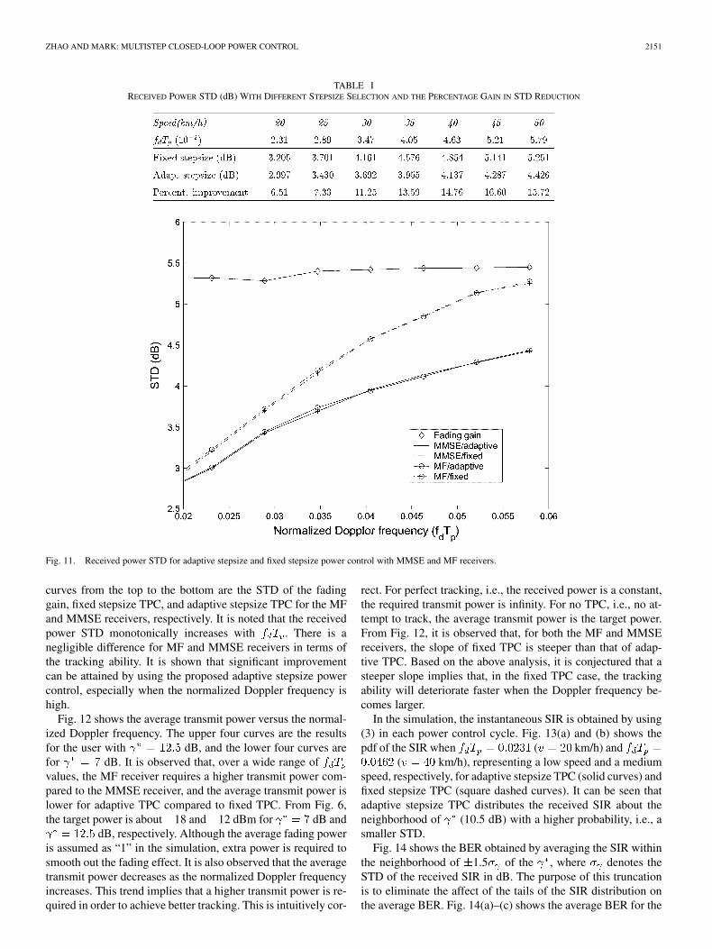
Fig. 12 shows the average transmit power versus the normal-ized Doppler frequency. The upper four curves are the resultsfor the user with dB, and the lower four curves arefor dB. It is observed that, over a wide range ofvalues, the MF receiver requires a higher transmit power com-pared to the MMSE receiver, and the average transmit power islower for adaptive TPC compared to fixed TPC. From Fig. 6,the target power is about 18 and 12 dBm for dB and
dB, respectively. Although the average fading poweris assumed as “1” in the simulation, extra power is required tosmooth out the fading effect. It is also observed that the averagetransmit power decreases as the normalized Doppler frequencyincreases. This trend implies that a higher transmit power is re-quired in order to achieve better tracking. This is intuitively cor-
rect. For perfect tracking, i.e., the received power is a constant,the required transmit power is infinity. For no TPC, i.e., no at-tempt to track, the average transmit power is the target power.From Fig. 12, it is observed that, for both the MF and MMSEreceivers, the slope of fixed TPC is steeper than that of adap-tive TPC. Based on the above analysis, it is conjectured that asteeper slope implies that, in the fixed TPC case, the trackingability will deteriorate faster when the Doppler frequency be-comes larger.
In the simulation, the instantaneous SIR is obtained by using(3) in each power control cycle. Fig. 13(a) and (b) shows thepdf of the SIR when ( km/h) and
( km/h), representing a low speed and a mediumspeed, respectively, for adaptive stepsize TPC (solid curves) andfixed stepsize TPC (square dashed curves). It can be seen thatadaptive stepsize TPC distributes the received SIR about theneighborhood of (10.5 dB) with a higher probability, i.e., asmaller STD.
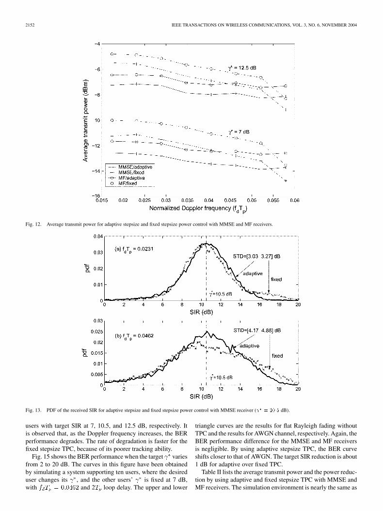
Fig. 14 shows the BER obtained by averaging the SIR withinthe neighborhood of 1.5 of the , where denotes theSTD of the received SIR in dB. The purpose of this truncationis to eliminate the affect of the tails of the SIR distribution onthe average BER. Fig. 14(a)–(c) shows the average BER for the
2152 IEEE TRANSACTIONS ON WIRELESS COMMUNICATIONS, VOL. 3, NO. 6, NOVEMBER 2004
Fig. 12. Average transmit power for adaptive stepsize and fixed stepsize power control with MMSE and MF receivers.
Fig. 13. PDF of the received SIR for adaptive stepsize and fixed stepsize power control with MMSE receiver ( = 10:5 dB).
users with target SIR at 7, 10.5, and 12.5 dB, respectively. Itis observed that, as the Doppler frequency increases, the BERperformance degrades. The rate of degradation is faster for thefixed stepsize TPC, because of its poorer tracking ability.
Fig. 15 shows the BER performance when the target variesfrom 2 to 20 dB. The curves in this figure have been obtainedby simulating a system supporting ten users, where the desireduser changes its , and the other users’ is fixed at 7 dB,with and 2 loop delay. The upper and lower
triangle curves are the results for flat Rayleigh fading withoutTPC and the results for AWGN channel, respectively. Again, theBER performance difference for the MMSE and MF receiversis negligible. By using adaptive stepsize TPC, the BER curveshifts closer to that of AWGN. The target SIR reduction is about1 dB for adaptive over fixed TPC.
Table II lists the average transmit power and the power reduc-tion by using adaptive and fixed stepsize TPC with MMSE andMF receivers. The simulation environment is nearly the same as
ZHAO AND MARK: MULTISTEP CLOSED-LOOP POWER CONTROL 2153
Fig. 14. BER versus normalized Doppler frequency (�1.5� neighborhood of the averaging).
Fig. 15. BER versus target SIR (f T = 0:0462; 2T delay).
that in Fig. 15, i.e., the target SIR for the desired user changesfrom 2 to 20 dB, and the target SIR for the interferers is fixed at7 dB. The three groups denote the results for the number of usersbeing 10, 20, and 28,2 denoting the light-load, medium-load,and high-load cases, respectively. Inside each group, the first
2With a Gold sequence of length 31, this is about the largest number of usersthat can be supported.
two rows are the average transmit power using MMSE and MFreceivers, and the third row is the power reduction (with italicnumbers) by using the MMSE over the MF receiver for adap-tive TPC. The remaining three rows list similar results for fixedTPC. Our results show that with the increase in the number ofusers, the power savings by using the MMSE receiver is moresignificant. When the number of users is relatively low, it is more

2154 IEEE TRANSACTIONS ON WIRELESS COMMUNICATIONS, VOL. 3, NO. 6, NOVEMBER 2004
TABLE IIAVERAGE TRANSMIT POWERS (dBm) AND POWER REDUCTION (dB) BY USING MMSE OVER MF RECEIVER (f T = 0:0462; 2T LOOP DELAY)
desirable to use the MF receiver because it is simpler to imple-ment and exhibits power consumption almost comparable to thatof the MMSE receiver.
In summary, the gain of the proposed adaptive TPC over thefixed TPC is two-fold: 1) adaptive TPC offers a better trackingability, leading to a reduced STD of the received power/SIR, anda better BER performance; and 2) the average transmit power islowered, leading to a reduction in power consumption.
V. CONCLUSION
A multistep adaptive closed-loop power control algorithmemploying either an MMSE or an MF receiver for a DS-CDMAsystem in the presence of Rayleigh fading is presented andevaluated. The control algorithm aims at minimizing the targetpower level and regulating the transmit power to closely trackthe variation of the fading gain. The CLPC scheme yields arelatively low standard deviation of the received power/SIR,and a relatively low bit error rate.
At the base station, a linear filter receiver is employed fordespreading. With the MMSE receiver, the target power andthe filter coefficients are updated iteratively. This forward looppower control algorithm is shown to be robust and convergesquickly to the optimal MMSE filter coefficients, as well as min-imizes the target power level. When the MF receiver is used,the filter coefficients assume the form of the signature sequence.At the mobile station, transmit power is updated with variablestepsizes, which are generated based on the power control com-mand history and information pertaining to the Doppler effectand fading statistics.
Simulation results show that the proposed MMSE/MF iter-ative algorithm can converge quickly. The proposed multistepadaptive TPC exhibits a better tracking ability than the fixed
stepsize TPC. The STD of the received power/SIR can be re-duced significantly, leading to a better BER performance. It isshown that the improvement becomes more significant as thenormalized Doppler frequency increases. In addition, adaptiveTPC also leads to a reduction in average transmit power. Nu-merical results indicate that the tracking ability of the MMSEand MF receivers is essentially similar, except that the averagetransmit power is lower with the MMSE receiver but is morecomplex to implement. From the implementation complexityand performance tradeoff point of view, the MF receiver maybe the appropriate choice in conjunction with the closed-looppower control strategy presented in the paper.
It is conjectured that the proposed adaptive stepsize algorithmcan be extended to fading models which include other fadingcomponents, e.g., Rician fading with different Rice factors. Theiterative update of the reference stepsize vector provides an ap-proach to track the variations of the fading gain as a function ofthe Doppler frequency.
It was mentioned in the Introduction that signals sent throughthe dedicated control channel in IMT-2000 can be used to adap-tively generate the variable stepsize to regulate the transmitpower level. Thus, the proposed multistep closed-loop powercontrol strategy can be used for third-generation and beyondwireless communication systems.
REFERENCES
[1] W. C. Y. Lee, “Overview of cellular CDMA,” IEEE Trans. Veh. Technol.,vol. 40, pp. 291–301, May 1991.
[2] A. M. Viterbi and A. J. Viterbi, “Erlang capacity of a power controlledCDMA system,” IEEE J. Select. Areas Commun., vol. 11, no. 6, pp.892–900, Aug. 1993.
[3] S. Ariyavisitakul and L. F. Chang, “Signal and interference statistics ofa CDMA system with feedback power control,” IEEE Trans. Commun.,vol. 41, pp. 1636–1634, Nov. 1993.

ZHAO AND MARK: MULTISTEP CLOSED-LOOP POWER CONTROL 2155
[4] J. W. Mark and W. Zhuang, Wireless Communications and Net-working. Englewood Cliffs, NJ: Prentice-Hall, 2003.
[5] J. W. Mark and S. Zhu, “Wideband CDMA in third generation cellularcommunication systems,” in Encyclopedia of Telecommunications, J.Proakis, Ed. New York: Wiley, 2002, vol. 5, pp. 2872–2883.
[6] A. Chockalingam, P. Dietrich, L. B. Milstein, and R. R. Rao, “Perfor-mance of closed-loop power control in DS-CDMA cellular systems,”IEEE Trans. Veh. Technol., vol. 47, pp. 774–789, Aug. 1998.
[7] I. Saarinen, A. Mammela, P. Jarvensiuv, and K. Ruotsalainen, “Powercontrol in feedback communications over a fading channel,” IEEE Trans.Veh. Technol., vol. 50, pp. 1231–1239, Sept. 2001.
[8] F. Adachi, M. Sawahashi, and H. Suda, “Wideband DS-CDMA for next-generation mobile communications systems,” IEEE Commun. Mag., vol.36, pp. 56–69, Sept. 1998.
[9] S. Nourizadeh, P. Taaghol, and R. Tafazolli, “A novel closed loop powercontrol for UMTS,” 3G Mobile Commun. Technol., pp. 56–59, 2000.
[10] C. C. Lee and R. Steele, “Closed-loop power control in CDMA systems,”Proc. IEEE, vol. 143, no. 4, pp. 231–239, Aug. 1996.
[11] J. W. Mark and S. Zhu, “Power control and rate allocation in multiratewideband CDMA systems,” in Proc. IEEE Wireless CommunicationsNetworking Conf., 2000, pp. 168–172.
[12] J. T. Wu and E. Geraniotis, “Power control in multi-media CDMA net-works,” in Proc. IEEE Vehicular Technology Conf., 1995, pp. 789–793.
[13] L. C. Yun and D. G. Messerschmitt, “Power control for variable QoS ona CDMA channel,” in Proc. IEEE Military Communications Conf., Oct.1994, pp. 178–182.
[14] U. Madhow and M. L. Honig, “MMSE interference suppresion for di-rect-sequence spread-spectrum CDMA,” IEEE Trans. Commun., vol. 42,no. 12, pp. 3178–3188, Dec. 1994.
[15] M. L. Honig, U. Madhow, and S. Verdú, “Blind adaptive multiuser de-tection,” IEEE Trans. Inform. Theory, vol. 41, no. 4, pp. 944–960, 1995.
[16] S. Ulukus and R. D. Yates, “Adaptive power control with MMSE mul-tiuser detectors,” in Proc. IEEE Int. Conf. Communications, 1997, pp.361–365.
[17] M. K. Varanasi and B. Aazhang, “Multistage detection in asynchronouscode-division multiple-access communications,” IEEE Trans. Commun.,vol. 38, pp. 509–519, Apr. 1990.
[18] P. S. Kumar and J. Holtzman, “Power control for a spread spectrumsystem with multiuser receivers,” in Proc. IEEE Int. Symp. Personal,Indoor, and Mobile Radio Communications, 1995, pp. 955–959.
[19] J. Zhang and E. K. P. Chong, “CDMA systems in fading channels: Ad-missibility, network capacity, and power control,” IEEE Trans. Inform.Theory, vol. 46, pp. 962–981, May 2000.
[20] R. D. Yates, “A framework for uplink power control in cellular radiosystems,” IEEE J. Select. Areas Commun., vol. 13, pp. 1341–1347, Sept.1995.
[21] W. C. Jakes, Microwave Mobile Communications. New York: Wiley,1993.
[22] L. Zhao and J. W. Mark, “Mobile speed estimation based on averagefade slope duration,” IEEE Trans. Commun., to be published.
[23] Japan’s Proposal for Candidate Radio Transmission Technology onIMT-2000: W-CDMA, June 1998.
Lian Zhao (S’99–M’03) received the Ph.D. degreein electrical and computer engineering from the Uni-versity of Waterloo, Waterloo, ON, Canada, in 2002.
From October 2002 to July 2003, she was aPostdoctoral Fellow with the Centre for WirelessCommunications, University of Waterloo. Shejoined the Electrical and Computer EngineeringDepartment, Ryerson University, Toronto, ON,Canada, as an Assistant Professor in August 2003.Her research interests are in the areas of wirelesscommunications, radio resource management for
WCDMA-based communication systems, error control, power control, channelmodeling, and wireless networks.
Jon W. Mark (M’62–SM’80–F’88–LF’03) receivedthe B.A.Sc. degree from the University of Toronto,ON, Canada, in 1962 and the M.Eng. and Ph.D.degrees from McMaster University, Hamilton, ON,Canada, in 1968 and 1970, respectively, all inelectrical engineering.
From 1962 to 1970, he was an Engineer and thenSenior Engineer with Canadian Westinghouse Co.Ltd., Hamilton. In 1970 he joined the Department ofElectrical and Computer Engineering, University ofWaterloo, ON, where he is currently a Distinguished
Professor Emeritus. He was Department Chairman during 1984–1990. In 1996he established the Centre for Wireless Communications at the University ofWaterloo and is currently its Founding Director. He was on sabbatical leave atthe IBM T. J. Watson Research Center, Yorktown Heights, NY, as a VisitingResearch Scientist (1976–1977); AT&T Bell Laboratories, Murray Hill, NJ,as a Resident Consultant (1982–1983); Laboratoire MASI, Université Pierreet Marie Curie, Paris, France, as an Invited Professor (1990–1991); and theDepartment of Electrical Engineering, National University of Singapore, as aVisiting Professor (1994–1995). He previously worked in the areas of adaptiveequalization, spread-spectrum communications, and antijamming securecommunication over satellites. His current research interests are in broadbandand wireless communication networks, including network architecture, routing,and control, and resource and mobility management in wireless and hybridwireless/wireline communication networks.
Dr. Mark was an Editor of the IEEE TRANSACTIONS ON COMMUNICATIONS
(1983–1990); the Technical Program Chairman of INFOCOM’89; a a memberof the Inter-Society Steering Committee of the IEEE/ACM TRANSACTIONS ON
NETWORKING (1992–2003); an Editor of Wireless Networks (1993-2004); andan Associate Editor of Telecommunication Systems (1994–2004).


![course.ece.cmu.eduece796/documents/MPEG-1... · Web viewThe following table indicates the scale factor multiplier used in the requantization equation for each stepsize. scalefac_scale[gr]](https://img.dokumen.tips/doc/110x75/60a73c6f53206e0f46230324/ece796documentsmpeg-1-web-view-the-following-table-indicates-the-scale-factor.jpg)