Embed Size (px)
Citation preview
arX
iv:1
602.
0395
4v1
[cs.
IT]
12 F
eb 2
016
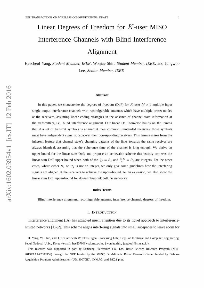
IEEE TRANSACTIONS ON WIRELESS COMMUNICATIONS, DRAFT 1
Linear Degrees of Freedom forK-user MISO
Interference Channels with Blind Interference
Alignment
Heecheol Yang,Student Member, IEEE, Wonjae Shin,Student Member, IEEE, and Jungwoo
Lee, Senior Member, IEEE
Abstract
In this paper, we characterize the degrees of freedom (DoF) for K-userM × 1 multiple-input
single-output interference channels with reconfigurable antennas which have multiple preset modes
at the receivers, assuming linear coding strategies in the absence of channel state information at
the transmitters, i.e., blind interference alignment. Ourlinear DoF converse builds on the lemma
that if a set of transmit symbols is aligned at their common unintended receivers, those symbols
must have independent signal subspace at their corresponding receivers. This lemma arises from the
inherent feature that channel state’s changing patterns ofthe links towards the same receiver are
always identical, assuming that the coherence time of the channel is long enough. We derive an
upper bound for the linear sum DoF, and propose an achievablescheme that exactly achieves the
linear sum DoF upper-bound when both of then∗
M= R1 and MK
n∗= R2 are integers. For the other
cases, where eitherR1 or R2 is not an integer, we only give some guidelines how the interfering
signals are aligned at the receivers to achieve the upper-bound. As an extension, we also show the
linear sum DoF upper-bound for downlink/uplink cellular networks.
Index Terms
Blind interference alignment, reconfigurable antenna, interference channel, degrees of freedom.
I. INTRODUCTION
Interference alignment (IA) has attracted much attention due to its novel approach to interference-
limited networks [1]-[2]. This scheme aligns interfering signals into small subspaces to leave room for
H. Yang, W. Shin, and J. Lee are with Wireless Signal Processing Lab., Dept. of Electrical and Computer Engineering,
Seoul National Univ., Korea (e-mail: [email protected], {wonjae.shin, junglee}@snu.ac.kr).
This research was supported in part by Samsung Electronics Co., Ltd, Basic Science Research Program (NRF-
2013R1A1A2008956) through the NRF funded by the MEST, Bio-Mimetic Robot Research Center funded by Defense
Acquisition Program Administration (UD130070ID), INMAC,and BK21-plus.

IEEE TRANSACTIONS ON WIRELESS COMMUNICATIONS, DRAFT 2
the desired signal dimensions. ForK-user interference channels (IC), each user achieves 1/2 degrees
of freedom (DoF) by the IA approach. In this scheme, global channel state information at transmitter
(CSIT) is necessary to align interfering signals at unintended receivers. However, global CSIT is
hard to achieve or even cannot be achieved in pracical systems. Even when global CSIT is available,
transmitters may obtain imperfect channel knowledge due toquantization error and feedback delay.
In the absence of CSIT, interference-limited networks cannot achieve the sum DoF more than 1 for
a general channel state condition [3]-[4]. However, it was introduced that the IA technique increases
the sum DoF without CSIT for a specific channel’s coherence time/bandwidth condition [5]-[6]. With
such a channel condition, a total ofK/2 DoF is achievable forK-user IC, which meets the outer
bound of the perfect CSIT scenario. This IA technique is referred to asblind interference alignment
(BIA). To make the specific channel condition more feasible, BIA through reconfigurable antenna
switching was proposed [7]. The DoF characterization with reconfigurable antennas has been studied
for various network scenarios with the assumption that the number of preset modes at a receiver
(N ) is not greater than the number of transmit antennas (M ), i.e., M ≥ N [7]-[10]. According to
[7], K-userM × 1 multiple-input single-output (MISO) broadcast channels (BC) achieve a total of
MKM+K−1 DoF with M preset modes of each reconfigurable antenna (i.e.,Ni = M,∀i, where receiver
i hasNi preset modes). By the result of [8], it was demonstrated thatthe sum DoF for MISO BC
cannot be increased even if a reconfigurable antenna has morethanM preset modes. Meanwhile, for
the IC scenario, a new achievable scheme for theK-user MISO IC is proposed in [9]-[10] for the
asymmetric antenna configuration, with the condition thatNi = Mi,∀i, where transmitteri (receiver
i) hasMi (Ni) antennas (preset modes), respectively. When transmitters are equipped with different
number of transmit antennas, the number of transmit symbolsis dependent on the number of transmit
antennas. IfMi = M for all i, theK-userM × 1 MISO IC also achieves a total of MKM+K−1 DoF as
theK-userM × 1 MISO BC.
The main contribution of this paper is to fully characterizethe DoF for theK-userM × 1 MISO
IC with reconfigurable antennas at the receivers by considering only linear coding strategies without
channel knowledge at transmitters, which includes the casewhere the number of preset modes is
greater than the number of transmit antennas, i.e.N > M . This is the most general result in the
literature. It was recently reported that a total of6/5 DoF is achievable for the 3-user single-input
single-output (SISO) IC with2 preset modes [11]. This result shows that extra preset modesat the
receivers in comparison with the number of transmit antennas can be exploited to increase the sum
DoF for the IC scenario, while extra preset modes cannot havea beneficial effect on the sum DoF
for the BC scenario [8]. Subsequently, it was simply extended in [12] that theK-user SISO IC with
2 receiver preset modes achieves a total of2KK+2 DoF. In this paper, we derive a new linear sum DoF
upper-bound for theK-userM × 1 MISO IC with N preset modes, including theN > M scenario.

IEEE TRANSACTIONS ON WIRELESS COMMUNICATIONS, DRAFT 3
In our approach to derive the linear sum DoF upper-bound, we focus on a lemma which claims that
if a set of transmit symbols is aligned at their common unintended receivers, those symbols must have
independent signal subspace at their intended receivers, which is induced from the characteristic of
the channel matrix with reconfigurable antenna switching. Specifically, we exploit the notable feature
that channel states of the links towards the same receiver must have the same changing pattern since
the changing pattern of the channel state is determined solely by the receiver’s preset mode pattern,
under the assumption that the coherence time of the channel is long enough. Remarkably, we show
that the linear sum DoF upper-bound is achievable whenn∗
M = R1 and MKn∗
= R2 are integers, where
n∗ represents the optimal number of preset modes amongN preset modes at each receiver, under
the linear scheme obtained by modifying the existing achievable scheme for the IC scenario in [10].
If these conditions are not satisfied, i.e., eitherR1 or R2 is not an integer, we give some guidelines
for an achievable scheme, which shows how to align interfering signals by introducing the concept
of an alignment set.
We also extend our approach to downlink/uplink cellular networks. There has been previous work
on the BIA scheme with reconfigurable antennas for cellular networks: the cluster-based frequency
reuse system [13]-[14], data sharing for cell-edge users [15]-[16], and the sum DoF characterizations
[17]-[19]. In this paper, we derive the linear sum DoF upper-bound for fully connected downlink
cellular networks with reconfigurable antennas at the users, by applying the same lemma for the IC
scenario. We also show this upper-bound implies that extra preset modes at the users compared with
base station’s antennas can be useful to increase the linearsum DoF without data sharing between
base stations. In addition, our result is applied to uplink scenario with reconfigurable antennas at the
base station by considering the effect of transmitter cooperation for the IC scenario with no CSIT.
The rest of this paper is organized as follows. In Section II,we introduce the system model and
the main results of this paper. In Section III, the linear sumDoF converse for theK-user MISO IC
is proved. We propose a new achievable scheme that exactly achieves the linear sum DoF upper-
bound in Section IV. In Section V, we also discuss the linear sum DoF for downlink/uplink cellular
networks. We conclude this paper in Section VI.
Notation: For a vectora, diag(a) represents a diagonal matrix whose diagonal entries are elements
of a. For matricesA andB, AT means the transpose ofA, span(A) denotes the space spanned
by the column vectors ofA, dim(A) is the dimension of span(A), and dim(A ∩B) represents the
dimension of the intersection of span(A) and span(B). For vector spacesA andB, ProjAcB denotes
the vector space induced by projectingB onto the orthogonal complement ofA. For r ∈ R, ⌊r⌋ is
the largest integer not greater thanr, and⌈r⌉ is the smallest integer not less thanr. For a, b ∈ N,
[a : b] denotes{a, a+1, . . . , b}. For setsA andB, A\B is the relative complement ofB in A. The
notation(nk
)is a k-combination of a setS, which hasn elements.

IEEE TRANSACTIONS ON WIRELESS COMMUNICATIONS, DRAFT 4
Fig. 1. System model forK-userM × 1 interference channels withN preset modes at the receivers.
II. SYSTEM MODEL & M AIN RESULTS
Consider theK-userM × 1 MISO IC with a reconfigurable antenna switching. The system has
K transmitters, each of which hasM transmit antennas, andK receivers which have a single
reconfigurable antenna withN preset modes each. We refer to it as(M,N,K)-IC from now on,
which is described in Fig. 1. We notateTS (RS ) to represent a set of transmitters (receivers) for
S ⊂ [1 : K], e.g.,T[1:3] = {Transmitter1,Transmitter2,Transmitter3}. It is simply notated asT (R)
andTa (Ra) to denoteT[1:K] (R[1:K]) and Transmittera (Receivera), respectively. AtRj , the transmit
signals fromTj are desired signals, while those from other transmitters (i.e.,T \ Tj) are interfering
signals. We denote theath antenna ofTi by i(a) for i ∈ [1 : K] anda ∈ [1 : M ], andB denotes a set
of all transmit antennas in the network asB = {1(1), . . . ,K(M)}. The preset mode ofRj at time t
is denoted bylj(t). We assume that channel coefficients remain constant duringthe symbol extension
period, i.e. the coherence time of the channel is long enough. In this scenario, since the channel state
varies according to the receiver’s preset mode, we represent the channel vector fromTi to Rj at
time t ashj,i(lj(t)) = [hj,i(1)(lj(t)) . . . hj,i(M)(lj(t))] ∈ C1×M , each entry of which is assumed to be
independent and identically distributed (i.i.d.). Then, the channel matrix from the transmit antennai(a)
to Rj overm channel uses is denoted byHmj,i(a) = diag([hj,i(a)(lj(1)) . . . hj,i(a)(lj(m))]). Meanwhile,
Ti sends∑M
a=1 di(a) symbols, and the transmit symbols of the transmit antennai(a) (a ∈ [1 : M ])
overm channel uses isxmi(a) =
∑di(a)
d=1 si(a),dvmi(a),d wheresi(a),d is thedth data symbol from transmit
antennai(a) andvmi(a),d ∈ Cm×1 is the transmit beamforming vector forsi(a),d which is comprised
of 0 and 1. We also denote the beamforming matrix of transmit antennai(a) overm channel uses as

IEEE TRANSACTIONS ON WIRELESS COMMUNICATIONS, DRAFT 5
Vmi(a) = [vm
i(a),1 . . .vmi(a),di(a)
]. WhenM = 1, we simplify the notations ofvmi(a),d and si(a),d asvm
i,d
andsi,d, respectively. The received signal atRj overm channel uses is
ymj =
M∑
a=1
Hmj,j(a)x
mj(a)
︸ ︷︷ ︸desired signals
+
K∑
i=1,i 6=j
M∑
a=1
Hmj,i(a)x
mi(a)
︸ ︷︷ ︸interfering signals
+zmj , (1)
wherezmj ∈ Cm×1 is the additive white Gaussian noise overm channel uses, each entry of which is
distributed asCN (0, 1). The transmitters are subject to the average transmit powerconstraintP .
According to the BIA concept using reconfigurable antennas proposed in [7], interfering signals
are aligned through a predetermined order of antenna switching, which is called preset mode pattern.
We define the preset mode pattern ofRj duringm channel uses asLmj = [lj(1) . . . lj(m)]. Since we
assume that channel coefficients remain constant during a symbol extension period, the channel state
varies depending on the receiver’s preset mode pattern. Therefore, the channel states of links towards
the same receiver have the same changing pattern. In addition, the system assumes that CSIT is not
available, and receivers have perfect channel knowledge. Lastly, the linear DoF (LDoF) ofK-tuple
(d1, . . . , dK) is achievable if there exists a set of beamforming vectors and preset mode patterns for
j ∈ [1 : K] almost surely, satisfying
dim(
ProjIcjspan([Hm
j,j(1)Vmj(1) · · ·Hm
j,j(M)Vmj(M)])
)= dj(m),
dj = limm→∞
dj(m)m ,
(2)
whereIj is the interference signal subspace atRj as
Ij = span([Hm
j,1(1)Vm1(1) · · ·Hm
j,j−1(M)Vmj−1(M) (3)
Hmj,j+1(1)V
mj+1(1) · · ·Hm
j,K(M)VmK(M)]
).
The LDoF regionD is the closure of the set of all achievable LDoF tuples satisfying (2), and the
linear sum DoF is given by
LDoFsum= max(d1,...,dK)∈D
K∑
j=1
dj . (4)
The main results on linear sum DoF upper-bound and achievability are as follows.
Theorem 1(DoF converse) : For theK-userM×1 MISO IC with N preset modes at each receiver,
the linear sum DoF is upper bounded by
LDoFsum≤ n∗K
K +⌈n∗
M
⌉(n∗ − 1)
, (5)
whereN = MΓ + α (0 ≤ α < M ), andn∗ represents the optimal number of preset modes among

IEEE TRANSACTIONS ON WIRELESS COMMUNICATIONS, DRAFT 6
N preset modes as
n∗ =
MΓ, N < M
⌈√KM
⌉, α ≤ N(MΓ−1)
K−Γ−1
N, N < M
⌈√KM
⌉, α > N(MΓ−1)
K−Γ−1
MΓopt, N ≥ M
⌈√KM
⌉(6)
whereΓopt = argminγ=
⌊√K
M
⌋
,⌈√
K
M
⌉
Mγ + Kγ .
Theorem 2 (DoF achievability): For theK-userM × 1 MISO IC with N preset modes at each
receiver, ifR1 andR2 are integers whereR1 = n∗
M , R2 = MKn∗
, andn∗ is determined by (6), the
linear sum DoF upper-bound (5) is achievable when beamforming vectors and preset mode patterns
are constructed asR2-usern∗ × 1 MISO IC according to [10].
Corollary 1 : For K-userM × 1 MISO IC with N preset modes at each receiver, the linear sum
DoF is
LDoFsum=n∗K
K +⌈n∗
M
⌉(n∗ − 1)
, (7)
wheren∗ is determined by (6),n∗ is a multiple ofM , andMK is divisible byn∗.
Proof: It is simply induced from Theorem 1 and 2.
We prove Theorem 1 and 2 in Section III and IV, respectively.
III. D OF CONVERSE
In this section, we derive the upper-bound of the linear sum DoF for theK-userM × 1 MISO
IC with reconfigurable antennas equipped withN preset modes at the receivers. To begin with, we
introduce key lemmas to prove the DoF converse, which is followed by the proof of Theorem 1. In
addition, we discuss the linear sum DoF upper-bound tendency as N increases, and compare this
result with finite state compound wireless network scenarios.
A. Key Lemmas
Beforehand, we introduce a lemma in [11] that shows an interesting feature of channel matrices with
reconfigurable antenna switching at receivers, which comesfrom the property of diagonal matrices.
Lemma 1 (Lemma 2 in [11]): IfH1v1 ∈ span(H2V2), whereH1 andH2 are twom×m full-rank
diagonal matrices with the same pattern, implying that their diagonal entries have the same changing
pattern,v1 is anm× 1 column vector,V2 is anm× d thin matrix, i.e.,d < m, and the entries ofv1
andV2 are generated independently of the values of the diagonal entries ofH1 andH2, thenv1 ∈span(V2).
Proof: We refer to Lemma 2 in [11].
IEEE TRANSACTIONS ON WIRELESS COMMUNICATIONS, DRAFT 7
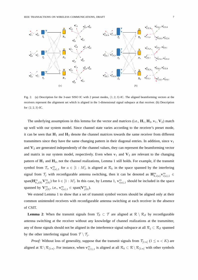
Fig. 2. (a) Description for the 3-user SISO IC with 2 preset modes,(1, 2, 3)-IC. The aligned beamforming vectors at the
receivers represent the alignment set which is aligned in the 1-dimensional signal subspace at that receiver. (b) Description
for (2, 2, 3)-IC.
The underlying assumptions in this lemma for the vector and matrices (i.e.,H1,H2,v1,V2) match
up well with our system model. Since channel state varies according to the receiver’s preset mode,
it can be seen thatH1 andH2 denote the channel matrices towards the same receiver from different
transmitters since they have the same changing pattern in their diagonal entries. In addition, sincev1
andV2 are generated independently of the channel values, they canrepresent the beamforming vector
and matrix in our system model, respectively. Even whenv1 andV2 are relevant to the changing
pattern ofH1 andH2, not the channel realizations, Lemma 1 still holds. For example, if the transmit
symbol fromTi, vmi(a),1 for a ∈ [1 : M ], is aligned atRk in the space spanned by the interfering
signal from Tj with reconfigurable antenna switching, then it can be denoted asHmk,i(a)v
mi(a),1 ∈
span(Hmk,j(b)V
mj(b)) for b ∈ [1 : M ]. In this case, by Lemma 1,vm
i(a),1 should be included in the space
spanned byVmj(b), i.e.,vm
i(a),1 ∈ span(Vmj(b)).
We extend Lemma 1 to show that a set of transmit symbol vectorsshould be aligned only at their
common unintended receivers with reconfigurable antenna switching at each receiver in the absence
of CSIT.
Lemma 2: When the transmit signals fromTS ⊂ T are aligned atR \ RS by reconfigurable
antenna switching at the receiver without any knowledge of channel realizations at the transmitter,
any of those signals should not be aligned in the interference signal subspace at allRj ⊂ RS spanned
by the other interfering signal fromT \ Tj.Proof: Without loss of generality, suppose that the transmit signals from T[1:n] (1 ≤ n < K) are
aligned atR\R[1:n]. For instance, whenvm1(1),1 is aligned at allRk ⊂ R\R[1:n] with other symbols

IEEE TRANSACTIONS ON WIRELESS COMMUNICATIONS, DRAFT 8
from T[1:n],
at Rk: Hmk,1(1)v
m1(1),1 ∈ span(Hm
k,j(a)Vmj(a)), (8)
for j ∈ [1 : n] anda ∈ [1 : M ]. Recall that transmitters have no knowledge about channel realizations,
andHmk,1(1) andHm
k,j(a) have the identical changing pattern of their diagonal entries. By Lemma 1,
vm1(1),1 ∈ span(Vm
j(a)), (9)
At the same time, ifvm1(1),1 is aligned in the interference signal subspace atRj ⊂ R[1:n] spanned by
the transmit signals fromTi ⊂ T \ Tj,
at Rj : Hmj,1(1)v
m1(1),1 ∈ span(Hm
j,i(b)Vmi(b)), (10)
for b ∈ [1 : M ]. This expression can be written as
at Rj: Hmj,1(1)v
m1(1),1 ∈ span(Hm
j,j(a)(Hmj,j(a))
−1Hmj,i(b)V
mi(b)). (11)
SinceHmj,1(1) andHm
j,j(a) have the same diagonal changing pattern,
vm1(1),1 ∈ span((Hm
j,j(a))−1Hm
j,i(b)Vmi(b)), (12)
by Lemma 1. From (9) and (12), sincev1(1),1 is included in both of the two vector spaces span(Vmj(a))
and span((Hmj,j(a))
−1Hmj,i(b)V
mi(b)), they have a non-zero dimensional intersection of the vector space.
Thus,
dim(Vmj(a) ∩ (Hm
j,j(a))−1Hm
j,i(b)Vmi(b)) > 0, (13)
and it leads to
dim(Hmj,j(a)V
mj(a) ∩Hm
j,i(b)Vmi(b)) > 0. (14)
It means thatHmj,j(a)V
mj(a) andHm
j,i(b)Vmi(b) have the intersection of the signal subspace atRj . For
Rj , Hmj,j(a)V
mj(a) is a desired signal fromTj, while Hm
j,i(b)Vmi(b) is an interference signal. Since
Hmj,j(a)V
mj(a) is contaminated by the interference signal fromTi, it can be said thatvm
1(1),1 should not
be aligned in the interference signal subspace at allRj ⊂ R[1:n] spanned by the transmit signal from
T \ Tj when it is aligned atR \R[1:n] with the other transmit symbols fromT[1:n] to guarantee the
interference-free signal subspace.
Lemma 2 implies that if transmit symbols fromTS are aligned in the interference signal subspaces
at their common unintended receivers, i.e.,R\RS , each of those symbols has independent subspace
at RS , although each symbol is only desired by one intended receiver. Motivated by Lemma 2, we
define the notion of analignment set.

IEEE TRANSACTIONS ON WIRELESS COMMUNICATIONS, DRAFT 9
Definition: If a set of transmit symbols fromTS are aligned in the 1-dimensional signal subspace
at their common unintended receivers,R\RS , while occupying independent signal subspaces at each
of their corresponding receivers,RS , they are calledalignment set AS .
Using this terminology, we can equivalently reinterpret the existing linear sum DoF results for
SISO IC and MISO IC scenarios introduced in [10] and [11], respectively.
Example 1: Consider 3-user SISO IC with two preset modes, i.e.,(1, 2, 3)-IC, which achieves a
total of 6/5 LDoF [11] in Fig 2-(a). Each user sends two symbols over 5-symbol extension, thereby
v51,1 and v5
3,2 are aligned in an 1-dimensional subspace atR2, v51,2 and v5
2,1 are aligned in an 1-
dimensional subspace atR3, andv52,2 andv5
3,1 are also aligned in an 1-dimensional subspace atR1.
It can be said that the alignment sets are constructed as
A{1,3} = {v51,1,v
53,2},
A{1,2} = {v51,2,v
52,1},
A{2,3} = {v52,2,v
53,1}.
(15)
At R1, althoughv52,1 andv5
3,2 are interfering symbol vectors, they occupy an independent1-dimensional
subspace each, since each of them is aligned with the different transmit symbol vectors fromT1 at the
unintended receivers. In a similar way, because each receiver sets aside 2-dimensional signal subspace
for the desired signals among a total of 5-dimensional signal space, it is observed that a total of 6/5
LDoF is achievable for 3 users.
Example 2: Consider another MISO IC scenario,(2, 2, 3)-IC, which achieves a total of 3/2 LDoF
[10] in Fig 2-(b). In this scenario, the transmit symbol vectors from each transmitter’s two antennas are
aligned in 1-dimensional signal subspace at other receivers. During 4-symbol extension, the transmit
symbol vectorsv41(1),1 andv4
1(2),1 can be aligned atR\R1 since they are desired to onlyR1. By the
same manner,v42(1),1 andv4
2(2),1 are aligned atR\R2, andv43(1),1 andv4
3(2),1 are aligned atR\R3.
In this case, each of the alignment sets include the transmitsymbols intended to a single receiver as
A{1} = {v41(1),1,v
41(2),1},
A{2} = {v42(1),1,v
42(2),1},
A{3} = {v43(1),1,v
43(2),1}.
(16)
With these alignment sets, each user gets 2 desired symbols during 4-symbol extension. Consequently,
each user achieves 2/4 LDoF, so that a total of 3/2 LDoF can be achieved. Compared to Example 1,
each user achieves a greater DoF by using two transmit antennas.
With regard to the alignment set, we claim an important lemmato derive the upper-bound.
Lemma 3: The alignment sets have the same cardinality to maximize the sum DoF upper-bound.
Proof: We defer the proof into Appendix.
According to Lemma 3, we only consider the symmetric case forthe cardinality of the alignment
sets. Thus, all alignment sets are assumed to haven transmit symbols. In addition, we introduce

IEEE TRANSACTIONS ON WIRELESS COMMUNICATIONS, DRAFT 10
a supplementary lemma that could be used to induce the linearDoF from the dimension of signal
subspaces.
Lemma 4 (Lemma 3 in [20]): For two matricesA andB with the same row size,
dim(ProjAcB) = dim([A B])− dim(A), (17)
whereA andB denotes span(A) and span(B), respectively. It can be derived by basic linear algebra,
thus its proof is omitted. We now extend the approach inspired by Lemma 2 to prove the linear sum
DoF converse for the general(M,N,K)-IC scenario.
B. Proof of Theorem 1
From the definition ofdj(m) and Lemma 4,
dj(m)=dim(
ProjIcjspan([Hm
j,j(1)Vmj(1) · · ·Hm
j,j(M)Vmj(M)])
)(18)
=dim([Hm
j,1(1)Vm1(1) · · ·Hm
j,K(M)VmK(M)]
)
−dim([Hm
j,1(1)Vm1(1) · · ·Hm
j,j−1(M)Vmj−1(M)
Hmj,j+1(1)V
mj+1(1) · · ·Hm
j,K(M)VmK(M)]
)
≤m− dim(Ij).
According to Lemma 3, we assume that all alignment sets consist of n transmit symbols. These
transmit symbols in the same alignment set are aligned at their common unintended receivers, while
each of those symbols occupies an independent signal subspace at all of their corresponding receivers.
Sincen transmit symbols are aligned in the 1-dimensional signal subspace at their common unintended
receivers,(n− 1) dimensions occupied by the interference signals are diminished. If we denote the
dimension of the aligned interfering signal subspaces occupied by a set ofn transmit symbols from
transmit antennasp1(q1), . . . , pn(qn) at their common unintended receivers bydI(p1(q1), . . . , pn(qn)),
the dimension of the signal subspace occupied by the interfering signals atRj can be calculated by
subtracting the dimension of the aligned interfering signal subspaces as
dim(Ij) =
K∑
k=1,k 6=j
dk(m)− (n− 1)∑
p1(q1)∈B,p1 6=j
(19)
· · ·∑
pn(qn)∈B,pn 6=j,
pn(qn)>pn−1(qn−1)
dI(p1(q1), . . . , pn(qn)),
where pn(qn) > pn−1(qn−1) means that the transmit antennapn(qn) is the latter one than the
transmit antennapn−1(qn−1) in B when B has an order for elements from1(1) to K(M) as
{1(1), . . . , 1(M), 2(1), . . . ,K(M)}. ForRj, dI(p1(q1), . . . , pn(qn)) is equal to dim(Hmj,p1(q1)
Vmp1(q1)
∩

IEEE TRANSACTIONS ON WIRELESS COMMUNICATIONS, DRAFT 11
· · · ∩Hmj,pn(qn)
Vmpn(qn)
). By rearranging (18) and (19), the total dimension of signalsubspaces over
m channel uses atRj is
K∑
j=1
dj(m)− (n− 1)∑
p1(q1)∈B,p1 6=j
(20)
· · ·∑
pn(qn)∈B,pn 6=j,
pn(qn)>pn−1(qn−1)
dI(p1(q1), . . . , pn(qn)) ≤ m.
The best strategy to compose the alignment set ofn transmit symbols is to reduce the number of their
corresponding receivers so as to be aligned in as many commonunintended receivers as possible.
For then transmit symbols fromn transmit antennas, the minimum number of their corresponding
receivers is⌈
nM
⌉with n transmit antennas from the
⌈nM
⌉transmitters, thereby a set ofn transmit
symbols can be aligned in the interference signal subspace at K −⌈
nM
⌉unintended receivers. By
summing up (20) over all the receivers,
K
K∑
j=1
dj(m)− (n− 1)(K −⌈ n
M
⌉)
∑
p1(q1)∈B(21)
· · ·∑
pn(qn)∈B,pn(qn)>pn−1(qn−1)
dI(p1(q1), . . . , pn(qn)) ≤ Km.
Meanwhile, according to Lemma 2, recall that if a transmit symbol is aligned with other(n − 1)
symbols at their common unintended receivers, it cannot be aligned with the other set of(n − 1)
symbols. This fact can be represented by the inequality as
∑
p1(q1)∈B,p1(q1)6=i(a)
· · ·∑
pn−1(qn−1)∈B,pn−1(qn−1)6=i(a),
pn−1(qn−1)>pn−2(qn−2)
(22)
dI(i(a), p1(q1), . . . , pn−1(qn−1)) ≤ di(a)(m),
wheredi(a)(m) denotes the dimension of the independent signal subspaces occupied by the transmit
symbols from transmit antennai(a) at Ri overm channel uses fori(a) ∈ B, i.e.,∑M
a=1 di(a)(m) =
di(m). From the fact thatKM ·(KM−1n−1
)is equal ton ·
(KMn
), we can derive the equality as
∑
i(a)∈B
( ∑
p1(q1)∈B,p1(q1)6=i(a)
· · · (23)
∑
pn−1(qn−1)∈B,pn−1(qn−1)6=i(a),
pn−1(qn−1)>pn−2(qn−2)
dI(i(a), p1(q1), . . . , pn−1(qn−1)))
= n ·∑
p1(q1)∈B· · ·
∑
pn(qn)∈B,pn(qn)>pn−1(qn−1)
dI(p1(q1), . . . , pn(qn)).

IEEE TRANSACTIONS ON WIRELESS COMMUNICATIONS, DRAFT 12
The left-hand side represents the dimension of the interference signal subspace occupied by the
alignment sets including the transmit symbol from transmitantennai(a), while the right-hand side
represents the dimension of the interference signal subspace occupied by all the alignment sets, which
does not separately consider the alignment sets including the transmit symbol from transmit antenna
i(a). To take (22) and (23) into account, (21) changes to
K
K∑
j=1
dj(m)− n− 1
n
(K −
⌈ n
M
⌉ ) K∑
j=1
dj(m) ≤ Km. (24)
Thus, we have
1
m
K∑
j=1
dj(m) ≤ nK
K +⌈
nM
⌉(n− 1)
. (25)
This formula represents the linear sum DoF upper-bound whenn preset modes amongN are used.
Subsequently, the number of transmit symbols in an alignment set,n, should be determined to
maximize the linear sum DoF upper-bound (25). To be separated at their intended receivers,n should
not be greater thanN since receivers have at mostN independent channel states. We define the
LDoF function depending onn as
D(n) =nK
K +⌈
nM
⌉(n− 1)
, n ≤ N, (26)
whereM , N , andK are given. Suppose that receivers have enough preset modes to align interfering
signals, i.e.,N ≥ MK. As it is observed in the LDoF function as
D(M(γ − 1) + β) < D(Mγ), 0 < β < M, γ, β ∈ N (27)
since the transmit symbols are aligned with a greater numberof interference symbols at the same
number of the unintended receivers whenn is a multiple ofM than the number of interference
symbols whenn is not a multiple ofM . Thus, letn be equal toMγ. Then, the LDoF function is
D(Mγ) =MγK
K + γ(Mγ − 1). (28)
To maximizeD(Mγ), we need to findγ which minimizesMK/D(Mγ) = Mγ − 1 +K/γ. By the
inequality of arithmetic and geometric means,
g(γ) = Mγ +K
γ, (29)
is minimized whenγ =√
KM . Sinceγ is an integer andg(γ) is a convex function, either
⌊√KM
⌋or
⌈√KM
⌉is a solution which minimizesg(γ). We refer to it asΓopt. Therefore, the linear sum DoF
upper-bound is maximized byn∗ as (6) whenN ≥ M ·⌈√
KM
⌉.

IEEE TRANSACTIONS ON WIRELESS COMMUNICATIONS, DRAFT 13
Fig. 3. Linear sum DoF upper-bound characterization forK-userM × 1 interference channels with blind interference
alignment through reconfigurable antenna switching.
Let us explore the case whereN = MΓ+α is smaller thanM ·⌈√
KM
⌉. Becauseg(γ) is a convex
function,
D(M(γ − 1)) < D(Mγ), γ <
⌈√K
M
⌉, (30)
By (27) and (30),
D(n) < D(MΓ), n < MΓ,Γ <
⌈√K
M
⌉. (31)
Meanwhile, it is easily shown that
D(Mγ + β1) < D(Mγ + β2), 0 < β1 < β2 < M, (32)
sinceD(Mγ + β2) shows the upper-bound of the case where the alignment sets include a greater
number of transmit symbols thanD(Mγ + β1), while the alignment sets are aligned at the same
number of unintended receivers. Consequently,n∗ should beMΓ or MΓ + α by considering the
inequalities (31) and (32).D(MΓ + α) shows the upper-bound when all the preset modes are used
to align interference signals, whileD(MΓ) shows the upper-bound when onlyMΓ preset modes are
used to align the alignment set at one more unintended receivers than the previous case. Thus, we
conclude thatn∗ is determined as (6) by comparingD(MΓ) andD(MΓ + α), i.e.,D(MΓ + α) is
greater thanD(MΓ) if α > N(MΓ−1)K−Γ−1 .
C. Discussion
In this section, we discuss the linear sum DoF upper-bound tendency asN increases. We also
show the linear sum DoF upper-bound for theK-user SISO IC, and compare it to the previous DoF
characterization results in [11]-[12] and finite state compound wireless network scenarios [22].
Fig. 3 shows the linear sum DoF upper-bound characterization for the K-userM × 1 IC with
reconfigurable antenna switching asN = MΓ + α increases according to the result of Theorem

IEEE TRANSACTIONS ON WIRELESS COMMUNICATIONS, DRAFT 14
1. WhenN < M (Γ = 0), n∗, which maximizes the upper-bound isN sinceα is always greater
than N(M ·0−1)K−0−1 = −N
K−1 . If N = M , the upper-bound is MKM+K−1 that is the same result as [10]. For
the Mγ < N < M(γ + 1) region, there is a distinct separation of linear sum DoF upper-bound
increase tendency by the criteria,α =⌈N(Mγ−1)K−γ−1
⌉. Whenα <
⌈N(Mγ−1)K−γ−1
⌉, the upper-bound does
not increase compared to theN = Mγ case sincen∗ is still Mγ as in (6). On the other hand,
when α ≥⌈N(Mγ−1)K−γ−1
⌉, the upper-bound can be enhanced by utilizing all the presetmodes since
n∗ = Mγ + α. This tendency continues until
γ = Γopt = argminγ=
⌊√K
M
⌋
,⌈√
K
M
⌉
Mγ +K
γ, (33)
according to (6). Even whenN increases beyondM · Γopt, the upper-bound stays the same. The
maximum sum DoF upper-bound with sufficiently largeN is close to MK2√MK−1
by assuming that
Γopt is close to√
KM .
Corollary 2 [21]: For theK-user SISO IC withN preset modes at the receivers, i.e.,(1, N,K)-IC,
the linear sum DoF is upper-bounded by
LDoFsum≤ n∗KK + n∗(n∗ − 1)
, (34)
where
n∗ =
N N <⌈√
K⌉,
argminn=⌊√K⌋,⌈√K⌉
n+ Kn N ≥
⌈√K⌉.
(35)
We simplify Theorem 1 for the SISO IC case by settingM = 1. It is observed that our result
includes previous work [11]-[12]. Moreover, we prove that preset modes more than 2 are also effective
for SISO IC to increase the linear sum DoF. According to the result, 3 preset modes increase the
linear sum DoF whenK ≥ 7 and 4 preset modes are effective whenK ≥ 13.
Remark 1 [Comparison with finite state compound wireless networks]:The considered system
model in this paper is similar to finite state compound wireless networks in [22] since the channel state
should be determined among elements of a finite set for both ofthe two system models. According
to Corollary 2, the linear sum DoF upper-bound forK-user SISO IC is close to K2√K−1
when⌊√
K⌋
and⌈√
K⌉
are close to√K. However, in [22], theK-user finite state compound IC achieves a total
of K/2 DoF even if CSIT is not available. The BIA scheme introduced in [5]-[6] also achieves the
full K/2 DoF for theK-user SISO IC by exploiting specific channel correlations. In this scheme,
the channel state of the interfering link is assumed to remain constant, while the channel state of
the direct links varies.1 This result is completely different from the result of the BCscenario that
1This assumption could be feasible, although it is an unusualscenario for practical communication systems, when all the
direct links are time-selective and all the interfering links are frequency-selective, or vice versa.

IEEE TRANSACTIONS ON WIRELESS COMMUNICATIONS, DRAFT 15
a total of MKM+K−1 DoF is achievable for theK-userM × 1 MISO BC scheme with reconfigurable
antennas at the receivers, which coincides with the achievable sum DoF of finite state compound BC.
It is interesting to note that the upper-bound for IC with a reconfigurable antenna cannot meet the
sum DoF for finite state compound IC, which is because the channel states’ changing pattern towards
the same receiver are always equivalent. When the direct link and the interfering link towards the
same receiver have the same changing pattern, interfering signals can be aligned at a limited number
of receivers as shown in Lemma 2. On the other hand, it causes no influence on the BC scenario
since the desired symbol and the interfering symbol are transmitted via the same link, thus the direct
link and the interfering link (the same as the direct link) always have the same changing pattern in
every system model as well as the reconfigurable antenna switching scheme. Consequently, it can
be said that the linear sum DoF upper-bound for theK-user SISO IC increases from 1 [3]-[4] to
K2√K−1
in the absence of CSIT by reconfigurable antenna switching, however, the fullK/2 DoF is
not achievable in this scheme due to the inherent feature that the channel states of the links towards
the same receiver inevitably have the identical changing pattern.
IV. D OF ACHIEVABILITY
We dedicate this section to show how the linear sum DoF upper-bound explained in Section III
can be achieved by each user’s preset mode pattern and beamforming vectors. We notaten∗
M and MKn∗
asR1 andR2, respectively, and classify three scenarios whetherR1 andR2 are integer or not: 1)R1
andR2 are integers 2)R1 is an integer, butR2 is not an integer 3)R1 is not an integer. We show
that the linear sum DoF upper-bound is achievable for the first case by proving Theorem 2. For the
other cases, we give some guidelines for an achievable scheme how to make an alignment set with
the transmit symbols.
A. R1 and R2 are integers. (n∗ is a multiple of M and MK is divisible by n∗.)
In this case, we modify the existing achievable scheme for the K-user MISO IC [10] to our
scenario. In Theorem 2, we show that ifR1 andR2 are integers whereR1 =n∗
M , R2 =MKn∗
, andn∗
is determined by (6), the linear sum DoF upper-bound (5) is achievable for theK-userM × 1 MISO
IC with N preset modes at each receiver when beamforming vectors and preset mode patterns are
constructed asR2-usern∗ × 1 MISO IC according to [10].
Proof of Theorem 2: According to Lemma 2, the transmit symbols in an alignment set cannot be
aligned at their corresponding receivers which desire one of the transmit symbols. When we groupn∗
transmit symbols to be aligned at their common unintended receivers, they have independent signal
subspaces at their corresponding receivers. It means that it is sufficient for the corresponding receivers
to have the same preset mode pattern to decode those transmitsymbols in an alignment set. First,

IEEE TRANSACTIONS ON WIRELESS COMMUNICATIONS, DRAFT 16
we partition the K transmitter-receiver pairs intoR2 groups of sizeR1. Note that the total number
of antennas for each group (consisting ofR1 users) isn∗ = MR1. We then design the beamforming
vectors and the preset mode patterns for an equivalentR2-usern∗×1 MISO IC by the method of [10],
where each one ofR2 transmitter-receiver pairs corresponds to a group ofR1 transmitter-receiver
pairs in our system model. Note also that the preset mode pattern for each receiver in the equivalent
system is shared by the receivers of its corresponding groupin the original system. Specifically,
based on the achievable scheme in [10], each transmit antenna sends(n∗ − 1)R2−1 transmit symbols
to achieve the linear sum DoF upper-bound, and the receiverscan decode the transmit symbols in the
alignment sets, which include their desired symbols. The beamforming vectors for each transmitter
coincide with those of the IC scheme in [10] as
Vmi(a) = V̂m
i′((i−1)M+a−(i′−1)n∗), (36)
whereV̂mi′ (b)
denotes the beamforming vector of thebth transmit antenna ofTi′ for R2-usern∗ × 1
MISO IC andi′
=⌈(i−1)M+a
n∗
⌉. Likewise, the preset mode patterns also coincide with those of the
IC scheme in [10] as
Lmj = L̂m
⌈j/R1⌉. (37)
whereL̂mj′
denotes the preset mode pattern ofRj′ for theR2-usern∗×1 MISO IC. By this achievable
scheme,R1 users achieve a total of n∗
n∗+R2−1 DoF, so that the achievable linear sum DoF is
LDoFsum =n∗ · R2
n∗ +R2 − 1(38)
=n∗ · MK
n∗
n∗ + MKn∗
− 1
=n∗ ·MK
MK + n∗(n∗ − 1)
=n∗K
K + n∗
M (n∗ − 1).
This result is equal to the linear sum DoF upper-bound in (5).
Example 3: Consider the case of(1, 2, 4)-IC. In this case,n∗ is equal to 2, therebyn∗ is a multiple
of M = 2 andMK = 4 is divisible byn∗, i.e.,R1 andR2 are integers. When two users are grouped
to act as a single user, they can be seen as the 2-user2 × 1 MISO IC. The transmit beamforming
vectors for each transmitter during 3-symbol extension are
v31,1 = v3
2,1 = [1 1 0]T , v33,1 = v3
4,1 = [1 0 1]T , (39)
when each user transmits one data symbol. The preset mode pattern for each receiver during 3-symbol
extension is
L31 = L3
2 = [1 2 1], L33 = L3
4 = [1 1 2], (40)

IEEE TRANSACTIONS ON WIRELESS COMMUNICATIONS, DRAFT 17
In this case, the received signal during 3-symbol extensionat R1 is
y31=
h1,1(1) h1,2(1) h1,3(1) h1,4(1)
h1,1(2) h1,2(2) 0 0
0 0 h1,3(1) h1,4(1)
s1,1
s2,1
s3,1
s4,1
+ z31. (41)
R1 can decodes1,1 and s2,1 by subtracting the received signal at time 3 from the signal at time 1.
Sinces1,1 is a desired symbol atR1, user 1 achieves 1 DoF during 3-symbol extension. Because
R2 has the same preset mode pattern asR1, it also achievess1,1 ands2,1 in the same way. On the
other hand,R[3:4] achieves3,1 ands4,1 by subtracting the received signal at time 2 from the signal
at time 1. Consequently, a total of4/3 DoF is achievable by this scheme. It coincides with the result
of Theorem 1.
B. R1 is an integer, but R2 is not an integer. (n∗ is a multiple of M and MK is not divisible by n∗.)
In this case, a new achievable scheme is required since the existing achievable scheme cannot be
directly applied. According to the proof of the LDoF converse, all the transmit symbols need to be
included in the alignment sets in order that an alignment sethasn∗ transmit symbols to achieve
the linear sum DoF upper-bound. If not, there is DoF loss compared to the upper-bound since some
transmit symbols are not optimally aligned at their unintended receivers. Therefore, users need to
increase the number of their transmit symbolsη times in order that the number of transmit symbols
from all transmitters is divisible by the cardinality of thealignment sets, i.e.,ηMK should be divisible
by n∗.
Example 4: Let us introduce the case of(1, 2, 5)-IC, wheren∗ = 2. Each user needs to send 2 data
symbols to achieve the linear sum DoF upper-bound, so that 10symbols are grouped to 5 alignment
sets. The alignment sets are constructed as
A{1,2} = {v71,2,v
72,1}, A{2,3} = {v7
2,2,v73,1},
A{3,4} = {v73,2,v
74,1}, A{4,5} = {v7
4,2,v75,1},
A{1,5} = {v75,2,v
71,1},
(42)
which is described in Fig. 4. The beamforming vectors for each data symbols during 7-symbol
extension can be determined as
v71,2 = v7
2,1 = [1 1 1 0 0 0 0]T , (43)
v72,2 = v7
3,1 = [0 1 0 0 1 0 0]T ,
v73,2 = v7
4,1 = [0 0 1 0 0 1 0]T ,
v74,2 = v7
5,1 = [0 0 0 0 1 0 1]T ,
v75,2 = v7
1,1 = [1 0 0 1 0 0 0]T .

IEEE TRANSACTIONS ON WIRELESS COMMUNICATIONS, DRAFT 18
The preset mode pattern corresponding to the beamforming vectors is
L71 = [1 1 2 2 1 2 1], L7
2 = [1 2 2 1 1 2 1],
L73 = [1 1 1 1 2 2 2], L7
4 = [1 1 1 1 1 2 2],
L75 = [1 1 1 2 1 1 2].
(44)
The received signal atR1 is (45). We can see that the alignment sets which have no desired signal
for R1, i.e., A{2,3}, A{3,4}, andA{4,5} are aligned in an 1-dimensional signal subspace, while the
desired signals forR1 and the grouped signal with them have independent signal subspaces. It can
be verified by showing thatR1 in (46), whose columns represent the vectors carrying all the desired
symbols and one symbol out of the interfering symbols of eachalignment set, has full rank. We also
verify that other users have the same DoF as user 1 by confirming R2, . . . ,R5 have full rank. By
this scheme, each user achieves 2 DoF over 7-symbol extension, so that the linear sum DoF is10/7,
which is the same as the upper-bound.
y7
1 =
h1,1(1) h1,1(1)
0 h1,1(1)
0 h1,1(2)
h1,1(2) 0
0 0
0 0
0 0
s1,1
s1,2
+
h1,2(1) 0 0 0 0 0 0 h1,5(1)
h1,2(1) h1,2(1) h1,3(1) 0 0 0 0 0
h1,2(2) 0 0 h1,3(2) h1,4(2) 0 0 0
0 0 0 0 0 0 0 h1,5(2)
0 h1,2(1) h1,3(1) 0 0 h1,4(1) h1,5(1) 0
0 0 0 h1,3(2) h1,4(2) 0 0 0
0 0 0 0 0 h1,4(1) h1,5(1) 0
s2,1
s2,2
s3,1
s3,2
s4,1
s4,2
s5,1
s5,2
+ z71 (45)
R1 ,
h1,1(1) h1,1(1) h1,2(1) 0 0 0 h1,5(1)
0 h1,1(1) h1,2(1) h1,2(1) 0 0 0
0 h1,1(2) h1,2(2) 0 h1,3(2) 0 0
h1,1(2) 0 0 0 0 0 h1,5(2)
0 0 0 h1,2(1) 0 h1,4(1) 0
0 0 0 0 h1,3(2) 0 0
0 0 0 0 0 h1,4(1) 0
, (46)
C. R1 is not an integer. (n∗ is not a multiple of M .)
In this case, the achievable scheme should be modified to equalize the number of symbol extensions
between users. Ifn∗ is not a multiple ofM , the total signal dimensions at each receiver could be
different. It causes different number of symbol extensionsbetween users, which makes it difficult to
design a proper achievable scheme. To make an appropriate beamforming vectors and preset mode

IEEE TRANSACTIONS ON WIRELESS COMMUNICATIONS, DRAFT 19
Fig. 4. Description for the 5-user SISO IC with 2 preset modes, i.e., (1, 2, 5)-IC.
patterns, users should increase the number of transmit symbols in order to equalize the number of
symbol extensions between users.
Example 5: Consider a(2, 3, 6)-IC scenario wheren∗ = 3. If each transmit antenna sends a
single transmit symbol, transmit symbols could be includedin the alignment set to be aligned at the
unintended receivers as follows
A{1,2} = {vm1(1),1,v
m1(2),1,v
m2(1),1},
A{2,3} = {vm2(2),1,v
m3(1),1,v
m3(2),1},
A{4,5} = {vm4(1),1,v
m4(2),1,v
m5(1),1},
A{5,6} = {vm5(2),1,v
m6(1),1,v
m6(2),1}.
(47)
Each alignment set occupies an 1-dimensional signal subspace at the unintended receivers, while it
occupies a 3-dimensional signal subspace at the corresponding receivers for each symbol to have an
independent subspace. In this situation,R1 needs 6-symbol extension since the alignment setsA{2,3},
A{4,5}, andA{5,6} occupy an 1-dimensional subspace andA{1,2} occupies a 3-dimensional subspace.
On the other hand,R2 needs 8-symbol extension becauseA{1,2} andA{2,3} occupy a 3-dimensional
subspace each. This is becauseR1 has the desired symbols (i.e.vm1(1),1,v
m1(2),1) only in A{1,2}, while
R2 has the desired symbols (i.e.vm2(1),1,v
m2(2),1) in A{1,2} andA{2,3}. To make all the receivers have
the same number of symbol extensions, we suppose that each transmit antenna sends three transmit

IEEE TRANSACTIONS ON WIRELESS COMMUNICATIONS, DRAFT 20
symbols. The transmit symbols could be included in the alignment set as
A1{1,2} = {v20
(1)1,1,v20(1)2,1,v
20(2)1,1},
A1{2,3} = {v20
(2)2,1,v20(3)1,1,v
20(3)2,1},
A1{4,5} = {v20
(4)1,1,v20(4)2,1,v
20(5)1,1},
A1{5,6} = {v20
(5)2,1,v20(6)1,1,v
20(6)2,1},
A2{1,2} = {v20
(1)2,2,v20(2)1,2,v
20(2)2,2},
A1{3,4} = {v20
(3)1,2,v20(3)2,2,v
20(4)1,2},
A2{4,5} = {v20
(4)2,2,v20(5)1,2,v
20(5)2,2},
A1{1,6} = {v20
(6)1,2,v20(6)2,2,v
20(1)1,2},
A2{2,3} = {v20
(2)1,3,v20(2)2,3,v
20(3)1,3},
A2{3,4} = {v20
(3)2,3,v20(4)1,3,v
20(4)2,3},
A2{5,6} = {v20
(5)1,3,v20(5)2,3,v
20(6)1,3},
A2{1,6} = {v20
(6)2,3,v20(1)1,3,v
20(1)2,3}.
(48)
In that case, all users have the desired signals in 4 alignment sets. Thus, they need 20-symbol exten-
sions because 4 alignment sets occupy a 3-dimensional subspace each, while other 8 alignment sets
occupy an 1-dimensional subspace. Therefore, each user achieves 6 DoF over 20-symbol extensions,
thus the linear sum DoF is 9/5, which meets the upper-bound for the (2, 3, 6)-IC. In this way of
constructing alignment sets, a proper achievable scheme can be designed, so that users have the
extension of the same number of symbols.
Remark 2: If the considered (M,N,K)-IC scenario does not meet the two conditions, 1)n∗ is a
multiple of M and 2)MK is divisible byn∗, the proposed achievable scheme in Theorem 2 cannot
be applied. Moreover, to align interfering signals at the receiver in order to meet the linear sum DoF
upper-bound, more transmit symbols need to be sent than introduced in Section IV-B and IV-C if
n∗ > 2. As an example, for theK-userM × 1 MISO IC scenario withM preset modes [10], each
transmitter sends(M−1)K−1 transmit symbols to achieve a total ofMKM+K−1 DoF, which is the linear
sum DoF upper-bound. We describe an alignment strategy where the number of transmit symbols for
each transmit antenna in Section IV-B and IV-C is sufficient to achieve the upper-bound. Thus, we just
suggest a guideline in Section IV-B and IV-C how the transmitsymbols from each transmit antenna
are aligned at the unintended receivers to meet the linear sum DoF upper-bound by introducing the
concept of an alignment set. It could be interesting future work to propose the general framework
for (M,N,K)-IC that can be applied even if the mentioned two conditionsare not satisfied.
V. EXTENSION TO CELLULAR NETWORKS
The linear sum upper-bound can be simply extended to fully connected interfering broadcast
channel, i.e., downlink cellular networks, with a similar approach inspired by Lemma 2.

IEEE TRANSACTIONS ON WIRELESS COMMUNICATIONS, DRAFT 21
Fig. 5. G-cell M × 1 MISO fully connected interfering broadcast channels, where K receivers exist in each cell.
Corollary 3 : For G-cell M × 1 MISO fully connected interfering broadcast channels whichare
illustrated in Fig. 5, whereK receivers exist in each cell equipped with a single reconfigurable antenna
with N preset modes, the linear sum DoF is upper-bounded by
LDoFsum≤ n∗KG
KG+⌈n∗
M
⌉(n∗ − 1)
, (49)
whereN = min{N,MG} is expressed asMΓ + α (0 ≤ α < M ), andn∗ represents the optimal
number of preset modes as
n∗ =
MΓ, N < M ·⌈√
KGM
⌉, α ≤ N(MΓ−1)
KG−Γ−1
N, N < M ·⌈√
KGM
⌉, α > N(MΓ−1)
KG−Γ−1
M · Γopt, N ≥ M ·⌈√
KGM
⌉(50)
whereΓopt = argminγ=
⌊√KG
M
⌋
,⌈√
KG
M
⌉
Mγ + KGγ .
Proof: It can be proved by a similar way as in Theorem 1. The main difference is
n∗ ≤ MG, (51)
since there are onlyMG transmit antennas in the network, i.e. the maximum number oftransmit
symbols in an alignment set is limited toMG. Thus, the maximum value ofn∗ is limited to N =
min{N,MG}. For the proof of Theorem 1, the maximum value ofn∗ is also limited to min{N,MK},
whereMK is the number of transmit antennas inK-userM×1 MISO IC. However, we just assumed
thatn∗ is limited toN since
MK > M · argminγ=
⌊√K
M
⌋
,⌈√
K
M
⌉
Mγ +K
γ, (52)

IEEE TRANSACTIONS ON WIRELESS COMMUNICATIONS, DRAFT 22
Fig. 6. K-cell fully connected interfering multiple access channels, whereM transmit antennas exist in each cell.
where the right-hand side means the value ofn∗ that results in the maximum linear sum DoF with
sufficiently largeN .
If extra preset modes at the receivers more than the number oftransmit antennas are not exploited,
fully connected interfering broadcast channels only achieve the linear sum DoF as a single cell sum
DoF, i.e., a total of MKM+K−1 DoF, not to be affected by inter-cell interference (illustrated by the dotted
line in Fig. 5). Thus, previous work on the sum DoF characterizations for downlink cellular networks
(e.g. macro-femto cellular networks [17], partially connected cellular networks [18]-[19]) assumes
that the base stations are able to do data sharing between them to serve the users with all the base
stations in their proximity. In the cellular networks, the sum DoF can be increased by data sharing
between the base stations when the users have enough preset modes to be served by contiguous base
stations. However, Corollary 3 shows that the linear sum DoFfor cellular networks can be increased
by extra preset modes without the help of data sharing between base stations. To exploit extra preset
modes at the receivers without data sharing, the alignment sets are constructed to include the transmit
symbols from the multiple base stations. These symbols are aligned at the other cell’s users and have
independent signal subspaces at multiple base stations’ users, while a general approach of interference
alignment for cellular networks is to align transmit symbols from a single base station at all of the
other cell’s users. By a similar approach to exploit extra preset modes in Theorem 1 and Corollary
3, partially connected cellular networks could achieve larger sum DoF than fully connected cellular
networks to take advantage of their partial connectivity.
We also extend Theorem 1 to fully connected interfering multiple access channel, i.e., uplink
cellular networks, by considering the effect of transmitter cooperation for the IC scenario with no
CSIT.
Corollary 4 : For K-cell fully connected interfering multiple access channels which are illustrated

IEEE TRANSACTIONS ON WIRELESS COMMUNICATIONS, DRAFT 23
in Fig. 6, where transmitters in each cell have totalM transmit antennas and each receiver is equipped
with a single reconfigurable antenna withN preset modes, the linear sum DoF is also upper-bounded
by (5) as in theK-userM × 1 MISO IC.
Proof: Without CSIT, there is no additional DoF gain by the transmitter cooperation, i.e. a single
transmitter withM transmit antennas is equivalent toM transmitters with a single transmit antenna
in terms of DoF perspective. Thus, fully connected interfering multiple access channels can be seen
asM × 1 MISO IC if
∑
s∈T k
Ms = M, (53)
for k ∈ [1 : K], whereT k is the set of transmitters in Cellk andMs denotes the number of transmit
antennas for transmitters.
VI. CONCLUSION
This work mainly introduces the theoretical DoF bound for the blind interference technique with
reconfigurable antenna switching, where a set of transmit symbols need to be aligned only at their
common unintended receivers. In this paper, we derive the linear sum DoF upper-bound for theK-
userM×1 MISO IC with reconfigurable antenna at the receivers, and without any channel knowledge
at the transmitter, which is induced from the characteristic of the channel matrix with reconfigurable
antenna switching. This approach is extended to cellular networks, thus we show that the linear sum
DoF can be increased by using sufficient number of preset modes without data sharing between base
stations. Moreover, we claim that the linear sum DoF upper-bound is achievable by modifying the
existing achievable scheme for MISO IC when certain conditions are satisfied. We also suggest a new
achievable scheme for other cases, where certain conditions are not satisfied, but a specific algorithm
to make beamforming vectors and preset mode patterns for theachievable scheme are not proposed.
A general framework will be investigated as future work.
APPENDIX
Proof of Lemma 3: Suppose that there areG alignment sets which includeng transmit symbols
each forg ∈ [1 : G]. We can derive the sum DoF upper-bound by calculating the dimension of the
desired signal subspace over the dimension of the interfering signal subspace at all the receivers. With
ng transmit symbols, an alignment set occupiesng dimensions of desired signal subspace, while it
also occupies( ⌈ng
M
⌉−1
)ng dimensions at their corresponding receivers. This alignment set is aligned
in an 1-dimensional interfering signal subspace atK −⌈ng
M
⌉common unintended receivers. Thus,
the dimension of the signal subspace occupied by the alignment set withng transmit symbols can be

IEEE TRANSACTIONS ON WIRELESS COMMUNICATIONS, DRAFT 24
expressed as
f(ng) = ng, (54)
h(ng) =( ⌈ng
M
⌉− 1
)ng +K −
⌈ng
M
⌉, (55)
wheref(ng) andh(ng) denote the dimensions of the desired signal subspace and interfering signal
subspace at all the receivers, respectively, which are occupied by an alignment set withng transmit
symbols. Then, the sum DoF upper-bound withG alignment sets is given by
1
m
K∑
j=1
dj(m) ≤∑G
g=1 f(ng) ·K∑G
g=1 f(ng) +∑G
g=1 h(ng)(56)
(a)
≤ f(n1) ·Kf(n1) + h(n1)
(57)
=n1K
K +⌈n1
M
⌉(n1 − 1)
, (58)
where Step(a) comes from the assumption thatn1 is the optimal cardinality of the alignment set as
f(n1)
f(n1) + h(n1)≥ f(ng)
f(ng) + h(ng), g ∈ [2 : G]. (59)
It means that the sum DoF upper-bound can be maximized when all alignment sets have the optimal
number of elements. This completes the proof.�
REFERENCES
[1] V. Cadambe and S. A. Jafar, “Interference alignment and degrees of freedom of theK–user interference channel,”IEEE
Trans. Inf. Theory, vol. 54, pp. 3425-3441, Aug. 2008.
[2] M. A. Maddah-Ali, A. S. Motahari, and A. K. Khandani, “Communication over MIMO X channels: Interference
alignment, decomposition, and performance analysis,”IEEE Trans. Inf. Theory, vol. 54, pp. 3457-3470, Aug. 2008.
[3] C. Huang, S. A. Jafar, S. Shamai, and S. Viswanath, “On degrees of freedom region of MIMO networks without channel
state information at transmitters,”IEEE Trans. Inf. Theory, vol. 58, no. 2, pp. 849-857, Feb. 2012.
[4] C. S. Vaze and M. K. Varanasi, “The degrees of freedom regions of MIMO broadcast, interference, and cognitive radio
channels with no CSIT,”IEEE Trans. Inf. Theory, vol. 58, no. 8, pp. 5354-5374, Aug. 2012.
[5] S. A. Jafar, “Exploiting channel correlations - simple interference alignment schemes with no CSIT,”in Proc. IEEE
Conf. Global Telecom. (GLOBECOM), Miami, FL, Dec. 2010.
[6] S. A. Jafar, “Blind interference alignment,”IEEE J. Sel. Topics Signal Process., vol. 6, no. 3, pp. 216-227, Jun. 2012.
[7] T. Gou, C. Wang, and S. A. Jafar, “Aiming perfectly in the dark-blind interference alignment through staggered antenna
switching,” IEEE Trans. Signal Process., vol. 59, no. 6, pp. 2734-2744, Jun. 2011.
[8] M. Yang, S.-W. Jeon, D. K. Kim, Linear degrees of freedom of MIMO broadcast channels with reconfigurable antennas
in the absence of CSIT, 2014 [Online]. Available: http://arxiv.org/abs/1409.5532v1
[9] Y. Lu and W. Zhang, “Blind interference alignment in the K-user MISO interference channel,”in Proc. IEEE Conf.
Global Telecom. (GLOBECOM), Atlanta, GA, Dec. 2013.
[10] Y. Lu, W. Zhang, and K. B. Letaief, “Blind interference alignment with diversity in K-user interference channels,”
IEEE Trans. Commun., vol. 62, No. 8, pp. 2850-2859, Aug. 2014.

IEEE TRANSACTIONS ON WIRELESS COMMUNICATIONS, DRAFT 25
[11] C. Wang, “Degrees of freedom characterization: the 3-user SISO interference channel with blind interference
alignment,”IEEE Commun. Lett., vol. 18, no. 5, pp. 757-760, May 2014.
[12] A. M. Alaa and M. H. Ismail, Degrees of freedom of the K-user SISO Interference channel with blind interference
alignment using staggered antenna switching, 2014 [Online]. Available: http://arxiv.org/abs/1408.6427v2
[13] C. Wang, H. C. Papadopoulos, S. A. Ramprashad, and G. Caire, “Design and operation of blind interference alignment
in cellular and cluster-based systems,”IEEE Inf. Theory and Applications Workshop (ITA), La Jolla, CA, Feb. 2011.
[14] C. Wang, H. C. Papadopoulos, S A. Ramprashad, and G. Caire, “Improved blind interference alignment in a cellular
environment using power allocation and cell-based clusters,” in Proc. Int. Conf. on Commun. (ICC), Kyoto, Japan, Jun.
2011.
[15] S. Akoum, C. S. Chen, M. Debbah, and R. W. Heath, “Data sharing coordination and blind interference alignment
for cellular networks”in Proc. IEEE Conf. Global Telecom. (GLOBECOM), Anaheim, CA, Dec. 2012.
[16] M. M. Cespedes, J. Plata-Chaves, D. Toumpakaris, and A.G. Armada, “On the choice of blind interference alignment
strategy for cellular systems with data sharing,”in Proc. Int. Conf. on Commun. (ICC), Sydney, Australia, Jun. 2014.
[17] M. M. Cespedes, J. Plata-Chaves, D. Toumpakaris, and A.G. Armada, “Cognitive blind interference alignment for
macro-femto cellular networks,”in Proc. IEEE Conf. Global Telecom. (GLOBECOM), Austin, TX, Dec. 2014.
[18] M. M. Cespedes, J. P. Chaves, D. Toumpakaris, S. A. Jafar, and A. G. Armada, “Blind interference alignment for
cellular networks,”IEEE Trans. Signal Process., vol. 63, no. 1, pp. 41-56, Jan. 2015.
[19] Y. Lu and W. Zhang, “Downlink blind interference alignment for cellular networks,”in Proc. IEEE Conf. Global
Telecom. (GLOBECOM), Austin, TX, Dec. 2014.
[20] S. Lashgari, A. S. Avestimehr, and C. Suh, “Linear degrees of freedom of the X-channel with delayed CSIT,”IEEE
Trans. Inf. Theory, vol. 60, no. 4, pp. 2180-2189, Apr. 2014.
[21] H. Yang, W. Shin, and J. Lee, “Degrees of freedom forK-user SISO interference channels with blind interference
alignment,” in Proc. IEEE Asilomar Conf. on Signals, Systems, and Computers, Pacific Grove, CA, Nov. 2015.
[22] T. Gou, S. A. Jafar, and C. Wang, “On the degrees of freedom of finite state compound wireless networks,”IEEE
Trans. Inf. Theory, vol. 57, pp. 3286-3308, Jun. 2011.