Embed Size (px)
Citation preview

IEEE TRANSACTIONS ON VEHICULAR TECHNOLOGY, accepted (2012-01-10), to be published. 1
Iterative Time-Variant Channel Estimation for802.11p Using Generalized Discrete Prolate
Spheroidal SequencesThomas Zemen∗, Senior Member, IEEE, Laura Bernado,Student Member, IEEE, Nicolai Czink, Member, IEEE,
and Andreas F. Molisch,Fellow, IEEE
Abstract—This paper deals with channel-estimation for orthog-onal frequency division multiplexing (OFDM) in time-varia ntwireless propagation channels. We particularly consider thechallenges of the IEEE 802.11p standard, the world-wide domi-nant system for vehicular communications. For historic reasons,802.11p uses a pilot pattern that is identical to the one usedin802.11a, which was initially designed for the estimation ofindoorchannels with no or little time variations. Therefore, this pilotpattern violates the sampling theorem for channels with both,large delay spread and large Doppler spread, as often occursinvehicular communications. To remedy this problem, we design arobust iterative channel estimator based on a two-dimensionalsubspace spanned by generalized discrete prolate spheroidalsequences. Due to the tight subspace design the iterative receiveris able to converge to the same bit error rate as a receiver withperfect channel knowledge. Furthermore, we propose a backwardcompatible modification of the 802.11p pilot pattern such that thenumber of iterations sufficient for convergence can be reducedby a factor of two to three, strongly reducing implementationcomplexity.
Index Terms—Time-variant channel estimation, generalizeddiscrete prolate spheroidal sequences, IEEE 802.11p, intelligenttransportation system, wireless vehicular communications.
I. I NTRODUCTION
Wireless communications for vehicle-to-vehicle or vehicle-to-infrastructure scenarios has many important applications,including collision avoidance, reduction of traffic congestion,wrong-way driving warning as well as enabling e-mobility[1], and thus has drawn great attention in the past years. Aninternational standard, Wireless Access in Vehicular Environ-ments (WAVE) [2] has been developed. Its physical-layer isbased on the 802.11p standard [3]. It is the main candidatefor implementation by major car manufacturers, and also
Parts of this work were performed in the project ROADSAFE, a scientificcooperation between FTW, ASFINAG, Kapsch TrafficCom, Fluidtime, andTU Wien, to improve vehicular communication systems. The project is co-funded by the industry partners, the Austrian Government, and the City ofVienna within the compentence center program COMET. ThomasZemen(corresponding author), Laura Bernado and Nicolai Czink are also supportedby the FTW project NOWIRE funded by the Vienna Science and TechnologyFund (WWTF) and NFN SISE S106 funded by the Austrian Science Fund(FWF).
T. Zemen, L. Bernad and N. Czink are with FTW TelecommunicationsResearch Center Vienna, Vienna, Austria (e-mail: [email protected],[email protected], [email protected]). A. F. Molisch is with the University of South-ern California, Los Angeles, CA 90037 USA (e-mail: [email protected]).
Copyright (c) 2012 IEEE. Personal use of this material is permitted.However, permission to use this material for any other purposes must beobtained from the IEEE by sending a request to [email protected].
supported by various programs in particular in the EuropeanUnion and Japan.
A main challenge of vehicular communications are therapidly changing radio propagation conditions. Many measure-ment campaigns have demonstrated high Doppler and delayspreads, and even non-stationarities of the channel statistics,see [1], [4] for an overview and further references. Conse-quently, robust channel estimation is especially important, butalso especially difficult, in such an environment.
The challenges are exacerbated by the design of trainingsignals in the 802.11p standard. In order to exploit existingchip designs and economies of scale, this standard is virtuallyidentical to the well-known IEEE 802.11a/g (WiFi) standard.However, while the training signal design works well for theenvironments where WiFi is normally operating in (indoorenvironments with little or no mobility), it does not work inconjunction with standard channel estimation techniques inmany vehicular propagation channels, namely those that haveboth a large delay spread and Doppler spread.
To combat difficulties in time-variant wireless channels, wecan exploit the fact that the time-variant frequency-selectiveimpulse responses of the channels are restricted to low-dimensional subspaces. Further improvements can be achievedby iterations between channel estimation and symbol deci-sions.
Related Literature:
A number of publications investigate the performance of802.11p [1], [5]–[7] in realistic vehicular channel with both,large delay and Doppler spread, demonstrating the need forimproved algorithms. Parallel to the present work [8] showsanimproved orthogonal frequency division multiplexing (OFDM)symbol wise decision directed channel estimation method thatdoes not need a standard modification but is limited to frameerror rates in the order of10−1. In [9] OFDM symbol wisedecision together with smoothing in the frequency domain andantenna diversity is investigated. In [10] a modified physicallayer in the form of time-domain differential modulation isproposed to remove the need for time-variant channel estima-tion. The insertion of additional pilot symbols is advocated ina non-backward compatible fashion in [11] and [12].
However, it turns out that it is difficult to reach a frameerror rate (FER) below10−1 in vehicular channels with the802.11p pilot pattern. Hence, low-complexity robust frame
2 IEEE TRANSACTIONS ON VEHICULAR TECHNOLOGY, accepted (2012-01-10), to be published.
based channel estimation methods must be investigated suchthat the correlation of the fading process can be exploitedjointly in time and frequency. At the same time the algorithmmust be also robust towards the non-stationary nature of thevehicular communication channel.
A number of existing papers deal with channel estimationin time-variant channels based on subspaces. In [13] a low-dimensional subspace spanned by discrete prolate spheroidal(DPS) sequences [14] is used. The subspace is designedaccording to the given maximum normalized Doppler shiftνDmax = vmaxfCTS/c0, which is determined by the maximumvelocity vmax, the carrier frequencyfC, the speed of lightc0,and the symbol durationTS. The square channel estimationbias obtained with the Slepian basis expansion is more thana magnitude smaller compared to the Fourier basis expansion(i.e., a truncated discrete Fourier transform) [15].
While [13] estimates the Slepian basis expansion coeffi-cients individually for every subcarrier in an OFDM systemfurther improvements can be obtained by exploiting the cor-relation between the individual subcarriers in the frequency-domain. For this purpose a truncated Fourier transform wasused in [16]. However, this approach is optimal only forsample-spaced path delays. For more realistic real-valuedpath delays Edfors et al. [17] exploited the correlation inthe frequency-domain by using the singular value decompo-sition of the channels covariance matrix which is assumedto be known. In [18] the singular value decomposition wascalculated in an adaptive manner using an estimate of thecovariance matrix. In [19], [20] a two-dimensional Wienerfilter is employed for time and frequency selective channelestimation.
Iterative channel estimation, i.e., alternate payload data esti-mation and channel estimation has been discussed in a numberof papers, see, e.g., [21]–[26]. The two-dimensional Wienerfilter is employed for iterative channel estimation in [27].In [27] a reduced complexity singular value decomposition(SVD) based low-rank approximation [28], [29] is shown aswell.
In [30] two successive Slepian subspace projections are usedfor time-variant frequency-selective channel estimation. Thisallows exploiting the correlation in the time- and frequency-domain without the need to estimate the channel covariancefunction and to perform an SVD. A two dimensional projectionon a fixed Slepian subspace is further explored in [31].However, the subspace in the frequency-domain is chosentwice as large as necessary, cf. [31, paragraph after (2)].
Contributions of the Paper:
• We further tighten the two dimensional subspace of [31]by using generalized DPS sequences [32] that allow fora generalized non-symmetric (and even discontiguous)band-limit in the time- and frequency-domain. With atight subspace we can further reduce the channel estima-tion mean square error (MSE).
• We validate the time-variant channel estimator using ageometry-based stochastic channel model (GSCM) in an802.11p compliant link level simulation [33]. The channel
model is obtained from vehicular channel measurements[34].
• We show that, with a tight subspace design, near-optimalchannel estimation can be still obtained iteratively in an802.11p compliant system, despite the above-mentioneddeficiencies of the training-signal design in this standard.
• Finally, we propose a transparent, backward-compatibleextension to the 802.11p standard allowing for reducedcomplexity channel estimation. This is achieved byadding an additional OFDM pilot symbol to the end ofthe otherwise standard compliant frame and by utilizingone of the reserved header bits.
Notation:
We denote a scalar bya, a column vector bya and itsi-thelement witha[i]. Similarly, we denote a matrix byA andits (i, ℓ)-th element by[A]i,ℓ. The transpose ofA is givenby AT and its conjugate transpose byAH. A diagonal matrixwith elementsa[i] is written as diag(a) and theQ×Q identitymatrix asIQ. The absolute value ofa is denoted by|a| and itscomplex conjugate bya∗. The largest (smallest) integer that islower (greater) or equal thana ∈ R is denoted by⌊a⌋ (⌈a⌉).We denote the set of all integers byZ, the set of real numbersby R and the set of complex numbers byC.
Organization of the Paper:
The OFDM signal model is presented in Section II. In Sec-tion III we introduce the geometry-based stochastic channelmodel used to simulate the time-variant impulse response ofa vehicular communication channel. For channel estimationat the receiver side a subspace channel model based ongeneralized DPS sequences is presented in Section IV and thecorresponding iterative estimator in Section V. In SectionVIthe 802.11p pilot pattern and our proposed enhancementare discussed. The numeric simulation results are shown inSection VII, together with a discussion of the iterative receivercomplexity. We draw conclusions in Section VIII.
II. SIGNAL MODEL
We consider the equalization and detection problem foran OFDM link [35], [36]. The OFDM system utilizesNsubcarriers and a cyclic prefix with lengthG. The transmissionis frame-oriented with frame lengthM , utilizes a bandwidthB and the sampling rate at the receiver side1/TC = B. TheOFDM symbol duration is given byTS = (N +G)TC.
Each frame containsS = |S| coded data symbolsb[m, q] ∀ [m, q] ∈ S wherem ∈ IM = {0, . . . ,M − 1}denotes the discrete time at rate1/TS, q ∈ IN denotesthe subcarrier index with frequency spacing1/(TCN) andSthe two dimensional data symbol position index set in thetime-frequency plane, respectively. For[m, q] /∈ S we defineb[m, q] = 0.
A binary information sequenceχ[m′′] of length 2SRC isconvolutionaly encoded with code rateRC resulting in asequence of code bitsc[m′], see Fig. 1. After interleavingand quadrature phase shift keying (QPSK) modulation with

ZEMEN et al.: ITERATIVE TIME-VARIANT CHANNEL ESTIMATION FOR 802.11P USING GENERALIZED DISCRETE PROLATE SPHEROIDAL SEQUENCES 3
c[m′]
Data Encoder Interl. Mapper
MUX
N
IFFT
cyclic prefixN +G
p[m, q]
P/S
b[m, q]
χ[m′′]
Fig. 1. Model of the OFDM transmitter.
Gray labeling the data symbols are mapped on the OFDMtime-frequency grid ,
b[Ss] =1√2(c[2s] + jc[2s+ 1]) ∀s ∈ IS , (1)
whereSs denoted thes-th element[ms, qs] of the setS in theOFDM time-frequency grid.
In each frameJ = |P| pilot symbolsp[m, q] ∀ [m, q] ∈ Pare transmitted, whereP denotes the pilot symbol positionindex. For [m, q] /∈ P we definep[m, q] = 0. The two setsP andS are non-overlapping. The pilot symbolsp[m, q] areadded, giving
d[m, q] = b[m, q] + p[m, q] . (2)
Subsequently, anN -point inverse discrete Fourier transformis carried out and a cyclic prefix of lengthG is inserted. AnOFDM symbol, including the cyclic prefix, has lengthN +Gsamples.
The time-variant frequency response
g(t, f) = gTx(f)gPh(t, f)gRx(f) (3)
contains the effects of the physical (non band-limited) channelgPh(t, f), as well as the band-limiting filter at the transmitterside gTx(f) and the receiver sidegRx(f), respectively. Thesampled time-variant frequency response, used for channelsimulation, is defined as
g′[n, q] := g(nTC, ϕ(q)/(NTC)) . (4)
The functionϕ(q) = ((q + N/2 mod N) − N/2) maps thesubcarrier indexq ∈ {0, . . . , N−1} into the discrete frequencyindexϕ = {0, . . . , N/2− 1,−N/2, . . . ,−1}.
Generally, in an OFDM system inter-carrier inteference iscaused by a time-variant channel impulse response. However,if the normalized Doppler bandwidthνD stays below a fractionǫ = 5 · 10−1 of the normalized subcarrier bandwidth
νDN
N +G< ǫ (5)
the inter-carrier interference is small enough to be neglectedfor the processing at the receiver side [37]–[39].
This condition is well fulfilled for IEEE 802.11p systemsup to a velocity of about1440 km/h ≈ 400m/s. Hence,we are able to define the sampled time-variant channel asg[m, q] := g(m(N +G)TC, ϕ(q)/(NTC)) = g′[m(N +G), q],temporally sampled at rate(N + G)/TC for the processingat the receive side. We can do this since the intercarrier
interference is expected to have only a minor impact onthe receiver performance. For the channel simulation we useg′[n, q] sampled at rate1/TC, hence all inter-carrier interfer-ence effects are fully present in the received signal.
The received signal after cyclic prefix removal and discreteFourier transform is
y[m, q] = g[m, q]d[m, q] + z[m, q] , (6)
where circularly symmetric complex white Gaussian noisewith zero mean and covarianceσ2
z is denoted byz[m, q]. Theoutput of an minimum MSE equalizer
d[m, q] =y[m, q]g[m, q]∗
σ2z + |g[m, q]|2 (7)
is used as input to a BCJR decoder [40] after de-mappingand de-interleaving. In (7) we denote byg[m, q] the channelestimate at time indexm and subcarrier indexq.
III. G EOMETRY-BASED STOCHASTIC MODEL FOR
WIRELESSWAVE PROPAGATION
The time-variant frequency response
g(t, f) = gTx(f)
(P−1∑
ℓ=0
ηℓ(t)e−j2πτℓ(t)f
)
︸ ︷︷ ︸
gPh(t,f)
gRx(f) (8)
can be described as the superposition ofP individual paths,given P is sufficiently large. Each path is characterized bythe complex time-variant weighting coefficientηℓ(t) and itsreal-valued time-variant delayτℓ(t).
We can approximate the non-stationary fading process aswide-sense stationary for the duration of asingle OFDM framem ∈ IM and q ∈ IN [41], [42]. Hence, we model the time-variant path delay asτℓ(t) = τℓ(0)− fℓt/fC for the durationof MTS wherefℓ denotes the Doppler shift of pathℓ. Withthis assumption and using (4) we obtain
g′[n, q] = gTx[q]gRx[q]
P−1∑
ℓ=0
ηℓe−j2πθℓϕ(q)ej2πνℓn/(N+G)
︸ ︷︷ ︸
gPh[n,q]
, (9)
whereνℓ = fℓTS denotes the normalized Doppler shift andθℓ = τℓ(0)/(NTC) the normalized path delay, respectively.The geometry-based wireless wave propagation model (9)is the basic foundation for accurate emulation of vehicularwireless wave propagation properties. It was validated formodeling wireless communication channels for cellular [43]–[45] as well as vehicular communication systems [34].
As shown in previous investigations [34], [46], the channelresponse in vehicular environments consists of the sum ofcontributions coming from different reflecting objects, eachone with strongly different statistical properties. The mostimportant contributions stem from (i) the line-of-sight (LOS)path between transmitter and receiver, (ii) discrete objects,either mobile (MD) or static (SD) producing reflections withalarger time delay and (iii) diffuse scattering (D) coming from

4 IEEE TRANSACTIONS ON VEHICULAR TECHNOLOGY, accepted (2012-01-10), to be published.
reflections on side walls of the road. Therefore we can rewritegPh[n, q] as
gPh[n, q] =η(LOS)0 [n]e−j2πθ(LOS)
0 ϕ(q)ej2πν(LOS)0 n/(N+G)+
NSD∑
ℓ=1
η(SD)ℓ [n]e−j2πθ(SD)
ℓϕ(q)ej2πν(SD)
ℓn/(N+G)+
NMD∑
ℓ=1
η(MD)ℓ [n]e−j2πθ(MD)
ℓϕ(q)ej2πν(MD)
ℓn/(N+G)+
ND∑
ℓ=1
η(D)ℓ [n]e−j2πθ(D)
ℓϕ(q)ej2πν(D)
ℓn/(N+G), (10)
where NSD, NMD, and ND denote the number of scatter-ing objects (SD, MD, and D), c.f. [34, (9)]. The detailedparametrization of (10) will be discussed in Section VII-B2.
IV. GENERALIZED DISCRETEPROLATE SPHEROIDAL
SUBSPACECHANNEL MODEL
We consider an OFDM system transmitting data-framesover a time-variant frequency-selective channel. Pilot symbolsare interleaved with data symbols in the time frequencyplane. Hence, we can observe the time-variant and frequency-selective channel for a certain region in time and frequencyduring the transmission of a single frame.
For channel estimation we are interested to represent thechannel in time and frequency by a low dimensional subspacesuch that a low-complexity reduced-rank (robust) Wiener filter[29] can be employed. For channel estimation we are interestedto design a subspace that minimizes the MSE. In general thisrequires the knowledge of the second order statistics. Theeigenvectors of the covariance matrix, the Karhunen-Loeveexpansion [47], are the optimal basis functions spanning thesubspace; see [17] for a treatment in the frequency-domainand [32, Section III.C] for the time-domain approach, re-spectively. However, vehicular communication channels showlocal-stationarity only, i.e., their second-order statistics canchange rapidly. Hence, estimation of second order statisticsin frame based communication systems is either difficult orimpossible.
Below, in Section IV-A, we introduce the concept of gen-eralized DPS sequences and we motivate and explain theirapplication for a two dimensional subspace model for time-variant frequency-selective channels in Section IV-B.
A. Generalized Discrete Prolate Spheroidal Sequences
The subspaceU spanned by time-limited snapshots of aband-limited (flat) fading process has an essential dimensiongiven by the time-bandwidth product [32]
D′(W ,M) = ⌈|W|M⌉+ 1 , (11)
where the interval
W =
I⋃
i=1
Bi = B1 ∪ B2 ∪ . . . ∪ BI (12)
defines the bandlimit [32, (16)] potentially consisting ofIdisjoint intervals. Each interval is defined asBi = (νi1, νi2),
i ∈ {1, . . . , I} and with ν11 ≤ ν12 ≤ . . . ≤ νI1 ≤ νI2. TheLebesgue measure ofW reads
|W| =I∑
i=1
(νi2 − νi1) . (13)
The same subspaceU is also spanned by generalized DPSsequences{ui[m,W ,M ]}, i ∈ {0, . . . ,M −1}}, time-limitedto m ∈ IM . The generalized DPS sequences are band-limitedto the regionW and their energy is most concentrated in theinterval IM , see [32, Definition 2]. They are the solutions to
M−1∑
ℓ=0
C[ℓ−m,W ]ui[ℓ,W ,M ] = λi(W ,M)ui[m,W ,M ]
(14)for m ∈ Z, where
C[k,W ] =
∫
W
ej2πkνdν , (15)
and
λi(W ,M) =
M−1∑
m=0|ui[m,W ,M ]|2
∞∑
m=−∞|ui[m,W ,M ]|2
(16)
denotes thei-th ordered eigenvalue also representing theenergy concentration ofui[m,W ,M ] within IM .
Note thatC[k,W ] is proportional to the covariance functionof a process exhibiting a constant spectrum with supportW .Equation (15) evaluates to
C[k,W ] =1
j2πk
I∑
i=1
(ej2πkνi2 − ej2πkνi1
)(17)
if the band-limiting regionW consists ofI disjoint intervals.
B. Two Dimensional Generalized DPS Channel Model
For a highly oversampled fading process|W| ≪ 1 theessential subspace dimensionD′(W ,M) ≪ M . This is thetypical situation for modern high rate communication systems.Due to the small degrees of freedom the detailed shape ofthe power spectral density becomes less important for theestimation error. Hence, the support of the power spectraldensity is the crucial parameter for the subspace design [13],[32], only. A similar reasoning was used for a robust Wienerfilter design in [19], [48].
Motivated by the structure of (9) we will representg[m, q]using a two dimensional subspace model
g[m, q] ≈Dt−1∑
i=0
Df−1∑
k=0
ui[m,Wt,M ]
· uk[ϕ(q) +N
2,Wf , N ]ψi,k , (18)
where {ui[m,Wt,M ],m ∈ IM , i ∈ IDt} spans the time-
domain subspace and{uk[q,Wf , N ], q ∈ IN , k ∈ IDf} spans
the frequency-domain subspace [30]. The generalized DPScoefficients are denoted byψi,k.
The time-domain subspace{ui[m,Wt,M ],m ∈ IM , i ∈IDt
} models a sequence in time, i.e., the channel coefficients

ZEMEN et al.: ITERATIVE TIME-VARIANT CHANNEL ESTIMATION FOR 802.11P USING GENERALIZED DISCRETE PROLATE SPHEROIDAL SEQUENCES 5
0ν
−νDmax νDmax
2νDmax
Fig. 2. Symmetric time-domain subspaceWt = [−νDmax, νDmax].
θmax
θmax
θ0
Fig. 3. Asymmetric frequency-domain subspaceWf = [0, θmax].
g[m, q] for a single subcarrierq and a finite time-periodm ∈ IM . The time-domain subspace is parametrized bythe maximum support of the Doppler power spectral densityWt = [−νDmax, νDmax], see Fig. 2.
Similarly, the frequency-domain subspace{uk[q,Wf , N ], q ∈ IN , k ∈ IDf
} models g[m, q] for asingle OFDM symbolm and a finite frequency-intervalq ∈ IN . The frequency-domain subspace is parametrizedby the maximum support of the power delay profileWf = [0, θmax], whereθmax = τmax/(NTC) and τmax is themaximum excess delay, see Fig. 3.
The subspace dimensionsDt(Wt,M) and Df (Wf , N)minimizing the MSE for a given SNR can be expressed as[32], [49]
D(W ,M) = argminD∈{1,...,M}
(
1
|W|M
M−1∑
i=D
λi(W ,M)
+DMσ2n
)
. (19)
V. I TERATIVE CHANNEL ESTIMATION
After inserting the subspace channel model (18) into thesignal model (6) we obtain
y[m, q] =(Dt−1∑
i=0
Df−1∑
k=0
ui[m,Wt,M ]
· uk[ϕ(q) +N
2,Wf , N ]ψi,k
)
d[m, q] + z[m, q] . (20)
Using the generalized DPS sequences, our channel estimationproblem is reduced to estimating the coefficientsψi,k. NotethatDtDf ≪ NM .
For the purpose of estimating the generalized DPS coeffi-cientsψi,k we rewrite (20) in matrix vector notation as follows.We collect the coefficientψi,k in the vector
ψ = [ψT0 , . . . ,ψ
TDt−1]
T , (21)
whereψi = [ψi,0, . . . , ψi,Df−1]
T . (22)
We collect the received data valuesy[m, q] for all m andqin one vector
y = [y[0, 0], . . . , y[0, N − 1], y[1, 0], . . . , y[1, N − 1],
. . . , y[M − 1, 0], . . . , y[M − 1, N − 1]]T. (23)
Similarly we define vectord containing the data valuesd[m, q]and the noise vectorz containing the noise valuesz[m, q].
We define the vector
f [m,Wt,M ] = [u0[m,Wt,M ], . . . , uDt−1[m,Wt,M ]]T
(24)containing the elements of the generalized DPS basis functionsfor a given time indexm.
Finally, we define theMN ×DtDf matrix
D = D
f [0,Wt,M ]T ⊗ f [ϕ(0) + N2,Wf , N ]T
...f [M − 1,Wt,M ]T ⊗ f [ϕ(0) + N
2,Wf , N ]T
...
...f [0,Wt,M ]T ⊗ f [ϕ(N − 1) + N
2,Wf , N ]T
...f [M − 1,Wt,M ]T ⊗ f [ϕ(N − 1) + N
2,Wf , N ]T
(25)
whereD = diag(d), allowing to write the signal model forestimating the generalized DPS coefficient vectorψ as
y = Dψ + z. (26)
We use the soft-symbol feedback from the BCJR decoder[40] to enhance the channel estimates iteratively. In the firstiteration only the pilots are used. We defineD similar to (25),where we substituted[m, q] collected ind with
d[m, q] = b[m, q] + p[m, q] (27)
containing the soft symbol feedbackb[m, q].The soft symbolsb[m, q] are defined according to
b[Ss] = Eb
(APP){b[Ss]} (28)
=1√2
(
Ec
(APP){c[2s]}+ jEc
(APP){c[2s+ 1]})
(29)
for s ∈ IS , where
Ec
(APP){c[m′]} = 2Pr(APP){c[m′] = +1 | c[m′]} − 1 (30)
calculates the expectation over the alphabet ofc which is{−1,+1}. By Pr(APP) we denote the a-posterior probability(APP) for the code symbol being+1 if c[m′] is observed,wherec[m′] is obtained from the equalizer outputd[m, q] afterde-mapping and de-interleaving [24], see also Fig. 5.
The linear minimum mean square error (MMSE) estimatorfor the generalized DPS coefficientsψ can be expressed as
ψ =(
DH∆
−1D + Cψ
−1)−1
DH∆
−1y (31)
following the derivation in [24, (30)-(39)], where
Cψ =1
|Wt||Wf |diag(λ(Wt,M)⊗ λ (Wf , N)) , (32)

6 IEEE TRANSACTIONS ON VEHICULAR TECHNOLOGY, accepted (2012-01-10), to be published.
λ(Wt,M) = [λ0(Wt,M), . . . , λDt(Wt,M)]T , (33)
and
[∆]m+Mq,m+Mq = σ2z +
1
|Wt||Wf |
·Dt−1∑
k=0
Df−1∑
i=0
λi(Wt,M)λk(Wf , N)
· |ui[m,Wt,M ]uk[ϕ(q) +N/2,Wf , N ]|2
· (1− |d[m, q]|2) . (34)
VI. PILOT PATTERN DESIGN
In time-variant channels, the channel coefficients changebetween OFDM symbols within a frame, which needs to betracked by the channel estimator. This is particularly trueforvehicular settings, where high Doppler spreads of the channelare to be expected. In these cases, the pilot structure playsasignificant role on how well these changes can be tracked bya channel estimator.
As discussed in [1] the pilot placement in the time-frequency grid in general needs to fulfill the sampling theorem.The maximum excess delayτmax determines how dense pilotsymbols must be transmitted in the frequency-domain. Hence,the maximum pilot spacing∆f (no. of subcarriers) shallsatisfy
∆f ≤ N
τmaxB. (35)
The Doppler spread determines how dense pilot symbols mustbe placed in time. The maximum spacing∆t (no. of OFDMsymbols) shall satisfy
∆t ≤B
2fD(N +G). (36)
Optimal pilot placement is discussed in [50], [51].
A. Standard IEEE 802.11p Pilot Pattern
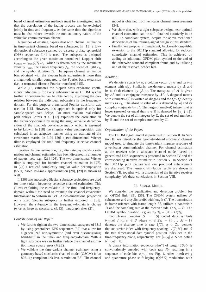
The pilot pattern of the IEEE 802.11 OFDM frame [3],[52] is shown in Fig. 4. After the so-called “short preamble”(not shown) for coarse timing estimation, the “long preamble”consists of two OFDM symbols containing pilot symbols, only.Additionally, four subcarriers are containing pilots throughoutthe whole OFDM frame. This pilot structure is usually termeda “block-comb” structure. It is particularly suited for quasi-static channels, where the block pilots are used for an initialchannel estimate, while the comb pilots shall ensure trackingof the phase for carrier frequency offset compensation.
Using the bound (35) we can see that for a time-variantchannel having an impulse response withτmax > 490 ns the802.11p pilot pattern will cause a degradation of the channelestimates due to aliasing.
For iterative receiver structures as discussed in this paperthe bounds (35) and (36) can be relaxed since the fed-back soft symbols are used as additional pilot information.However, if (35) and (36) are strongly violated, the num-ber of iterations until convergence increases or the iterativereceiver convergence stops early [53]. In Section VII we
time
fre
qu
en
cy
m
q
pilot
data
header
postamble
Fig. 4. Pilot pattern in an 802.11 OFDM frame, extended by theproposedtransparent postamble.
provide numeric simulation results further detailing the effectof the 802.11p pilot pattern on iterative channel estimation invehicular channels.
B. Improved Pilot Pattern
The increased number of iterations needed due to the802.11p pilot pattern that violates (35) and (36) leads to highcomputational complexity for the hardware design. For thisreason, we advocate to use an improved pilot symbol pattern,by appending another OFDM pilot symbol as postamble tothe OFDM frame as indicated in Fig. 4. The existence of thispostamble is announced in the “reserved” bit of the headerstructure [3].
It is known that this choice is still suboptimal for channeltracking [50], [51]. However, the advantage of this choiceis that this pilot pattern is backwards compatible to theestablished standard:
• New receivers check the value of the “reserved” bit inthe header. When set, the postamble is used for improvedchannel estimation.
• Conventional receivers ignore the “reserved” bit, butobtain the number of OFDM symbols in a frame fromthe “length” field of the header. By that, they are simplyignoring the postamble.
With the postamble the maximum excess delay is nowdetermined by the cyclic prefix
τmax< G/B (37)
and the maximum Doppler bandwidth depends on the framelengthM ,
fDmax< B/(2M(N +G)) . (38)
VII. N UMERIC SIMULATION RESULTS
In this section we present numerical simulation resultsobtained with an 802.11p compliant link level simulation.
A. IEEE 802.11p Link Level Simulator
An 802.11p [3] compliant link level simulator implementedin MATLAB is used to evaluate the iterative time-variantchannel estimator. The building blocks of the simulator aredepicted in Fig. 5, showing the transmitter, channel model,and receiver with iterative channel estimation.

ZEMEN et al.: ITERATIVE TIME-VARIANT CHANNEL ESTIMATION FOR 802.11P USING GENERALIZED DISCRETE PROLATE SPHEROIDAL SEQUENCES 7
Transmitter
Encoder
Receiver
Interleaver
Mapper
Pilot insertion
Modulator
Convolution
Inpuls resp. Noise
+
BCJR decoder
Deinterleaver
Demapper
LMMSE det.
Interleaver
Mapper
Channel est.
Demodulator
d[m, q]
c[m′]
ξ[m′′]
APP
b[m, q]
y[m, q]
g′[n, q] z
Fig. 5. Schematic structure of the 802.11p link-level simulator with iterativechannel estimation.
The 802.11p standard uses a system bandwidthB =10MHz, the cyclic prefix has lengthG = 16 samples,corresponding to a maximum tolerable excess delay of1.6µs(or 480m propagation distance). Of theN = 64 subcarriersonly 52 are utilized for data transmission to provide an upperand lower guard band. We assume a carrier frequency offC = 5.9GHz.
The 802.11p standard supports eight different coding andmodulation schemes, that allow for data rate adaptation rang-ing from 3 to 27 Mb/s [1, Sec. III.B]. In this paper we presentresults using coding and modulation scheme 3 at 6 Mb/s.This scheme uses quadrature phase shift keying (QPSK) (withsymbol mapper rateRS = 2) and a convolutional code withconstraint length 7 and code rateRC = 1/2.
We present simulation results for two different types ofchannel models for a vehicle driving atv = 100 km/h ≈28m/s ≈ 62mph communicating with a fixed infrastructureaccess point (vehicle-to-infrastructure):
1) A Rayleigh fading channel with an exponentially decay-ing power delay profile with root mean square (RMS)delay spreadτRMS = 0.4µs and a Clarke Dopplerspectrum [54] for each tap modeling a non line-of-sight scenario (e.g. the line-of-sight to the infrastructureaccess point is blocked by another vehicle). This modelis similar to the ”RTV-Expressway” tap delay line modeldescribed in [55].
2) A geometry-based stochastic channel model (GSCM)[34] implementing a vehicle-to-infrastructure scenarioshown in [1, Fig. 18] that allows to model the non-stationary properties of the vehicle-to-infrastructure linkwith a dominant line-of-sight propagation path (e.g. theaccess point is mounted on an elevated position on amotorway gantry).
Both channel models are implemented using fourfold over-sampling. The bit-error-rate (BER) results will be shownversusEb/N0 whereEb denotes the energy per bit andN0
denotes the noise power spectral density. Hence, we calculatethe variance of the additive symmetric complex white Gaussian
noise according to
1
σ2z
=Eb
N0RSRC
N
N +G
· M ′
M ′ +MPr +MH +MPo
NDa
NDa +NPi, (39)
whereM ′, MPr, MH, and MPo are the number of OFDMsymbols contained in the data, preamble, header, and postam-ble fields, respectively. The number of data subcarriers isdenoted byNDa and the number of pilot subcarriers byNPi. For all simulations,NDa = 48, NPi = 4, MPr = 2,MH = 1 and MPo ∈ {0, 1} depending on the presenceof the postamble pilot OFDM symbol. This corrects for theadditional transmit energy used for the cyclic prefix, pilots andheader information. The generated channel impulse responsesare normalized1 to have average energy 1. Expressed by thetime-variant frequency response it reads
Em
{N−1∑
q=0
|g[m, q]|2}
= N , (40)
due to Parcevals’s theorem. The transmitter sends a framecontaining{200, 400, 800} bytes, which corresponds to a totalframe length ofM = {37, 71, 137} OFDM symbols withoutpostamble andM = {38, 72, 138} with postamble, respec-tively. The presented results are averaged over 500 channelrealizations for the non line-of-sight and over 1000 channelrealization for the line-of-sight scenario, respectively.
For the parameters of 802.11p andM = 37, (37) and(38) provide the following bounds:τmax < 1.6µs andfD <1.6 kHz (300 km/h). These are sufficient for most vehicularscenarios
B. Simulation Results
We will compare our simulations results with the baseline performance shown in [1, Fig. 21] for the exponentiallydecaying power delay profile and Clarke’s Doppler spectrumin non line-of-sight situations and with [1, Fig. 22] for thenon-stationary model with strong line-of-sight component.
In both cases a non-iterative least-square or linear minimumMSE estimator was used in [1] to demonstrate the currentperformance of common-of-the-shelf chip sets. A bit errorfloor at10−1 for the non line-of-sight case and at10−4 for theline-of-sight case at anEb/N0 > 20 dB was found in [1] dueto the bad match of the 802.11p pilot pattern to a time-variantvehicular channel. A similar result is also reported in [56].
In the following we will present numeric simulation resultsdemonstrating the improved performance of the iterative re-ceiver developed in this paper and the benefit of the modifiedbackward compatible pilot pattern.
1) Vehicular non Line-of-Sight Scenario: Figure 6 showsthe BER versusEb/N0 using the 802.11p compliant pilotpattern for channel estimation. The solid line without markersshows the BER with perfect channel state information (CSI) atthe receiver side. The line with the circle markers shows the
1For the GSCM (10) the normalization can be achieved since theattenuationof each pathηℓ is known.

8 IEEE TRANSACTIONS ON VEHICULAR TECHNOLOGY, accepted (2012-01-10), to be published.
1 2 3 4 5 6 7 8 9 10 1110
−4
10−3
10−2
10−1
Eb/N
0 [dB]
BE
R
DPS, iteration 1DPS, iteration 2DPS, iteration 3DPS, iteration 4DPS, iteration 5block LSblock comb MMSEperfect CSI
Fig. 6. Bit error rate (BER) versusEb/N0 for iteration {1, . . . , 5} for aframe lengthM = 37, full 802.11p compliant (no postamble). The vehiclesmoves atv = 100 km/h, the channel model uses a Clarke Doppler profile foreach channel tap. The power delay profile is exponentially decaying with rootmean square delay spread0.4µs modeling a Rayleigh fading non line-of-sightscenario.
BER performance after the first iteration. Hence, a receiverwithout iterative channel estimation shows poor performance,with a BER of about10−1 at Eb/N0 = 11 dB. Additionally,we show the base line performance from [1, Fig. 21] for (i) theblock least square estimator (block LS) where only the firsttwo pilot symbols are used for channel estimation and (ii)the block comb MMSE estimator where the four comb pilotsubcarriers are employed to estimate the channel covariancefunction used then for MMSE channel estimation.
For a practical communication system the frame error rate(FER) is of high importance. In Fig. 7 we show the FER forthe same scenario as in Fig. 6. Clearly, most frames can bereceived without error and only a small number of framescontain multiple errors. Hence the bit-errors occur in burstsdue to the time and frequency selective channel.
When the receiver makes re-use of the already decoded bitsand their associated APPs, by running the receiver algorithmiteratively the FER decreases and approaches the one forperfect CSI. We obtain FERs below10−1 from the 3rditeration on, with the FER curve converging to that of perfectCSI after 4 iterations.
Nevertheless, the price we have to pay at the receiverside for this improvement is an increased complexity of thehardware implementation2, see Sec. VII-C for more details.To reduce this complexity we evaluate our proposal addingan extra dedicated OFDM pilot symbol at the end of theframe, described previously as transparent postamble. Thisresults in a strongly improved channel estimate already afterthe first iteration, as depicted in Fig. 8. A FER below10−1
is obtained forEb/N0 > 10.5 dB with a distance of about0.8 dB to the FER curve with perfect CSI. Convergence tothe FER curve with perfect CSI is achieved already after the
2For every iteration of the receiver the chip area needs to be increased byan additional BCJR decoder, as well as a frame storage, channel estimationand data detection logic to allow for a continuous pipelinedoperation.
1 2 3 4 5 6 7 8 9 10 1110
−2
10−1
100
Eb/N
0 [dB]
FE
R
DPS, iteration 1DPS, iteration 2DPS, iteration 3DPS, iteration 4block LSblock comb MMSEperfect CSI
Fig. 7. Frame error rate (FER) versusEb/N0 for iteration{1, . . . , 4} for aframe lengthM = 37, full 802.11p compliant (no postamble). The vehiclesmoves atv = 100 km/h, the channel model uses a Clarke Doppler profile foreach channel tap. The power delay profile is exponentially decaying with rootmean square delay spread0.4µs modeling a Rayleigh fading non line-of-sightscenario.
1 2 3 4 5 6 7 8 9 10 1110
−2
10−1
100
Eb/N
0 [dB]
FE
R
DPS, iteration 1DPS, iteration 2perfect CSI
Fig. 8. Frame error rate (FER) versusEb/N0 for the first two iterations fora frame length ofM = 37, with backward compatible transparent postamble.The vehicles moves atv = 100 km/h, the channel model uses a ClarkeDoppler profile for each channel tap. The power delay profile is exponentiallydecaying with root mean square delay spread0.4µs.
second iteration. Hence, the transparent postamble allowsfora complexity reduction by a factor of two in the non line-of-sight case analyzed in Fig. 7 and Fig. 8
In Fig. 9 we plot the FER as a function of the number ofiterations at the receiver for different frame size at a fixedEb/N0 = 11 dB. Circular markers depict results with thetransparent postamble, the square markers are used for theones without postamble, and the lines without markers showthe FER obtained with perfect CSI. Different line-styles areused to denote the length of the frame.
As expected, with increasing number of iterations, the FERconverges towards the one with perfect CSI. The slope ofthe curves with transparent postamble is steeper than with-

ZEMEN et al.: ITERATIVE TIME-VARIANT CHANNEL ESTIMATION FOR 802.11P USING GENERALIZED DISCRETE PROLATE SPHEROIDAL SEQUENCES 9
1 2 3 4 5 6 710
−2
10−1
100
number of iterations
FE
R
200 byte, postamble400 byte, postamble800 byte, postamble200 byte, no postamble400 byte, no postamble800 byte, no postamble200 byte, perfect CSI400 byte, perfect CSI800 byte, perfect CSI
Fig. 9. Frame error rate (FER) versus number of iterations atanEb/N0 =11 dB for varying frame size of{200, 400, 800} bytes. The vehicles movesat v = 100 km/h, the channel model uses a Clarke Doppler profile for eachchannel tap. The power delay profile is exponentially decaying with root meansquare delay spread0.4µs.
Parameters LOS MD SD DG0 [dB] -20 -80+24n -80+24n 50n 1.8 U [0,3.5] U [0,3.5] 6.4
TABLE IGSCMPARAMETERS MODIFICATIONS FOR THE
VEHICLE-TO-INFRASTRUCTURE SCENARIO RELATIVE TO[34, TABLE I].G0 DENOTES THE REFERENCE POWER ANDn THE PATHLOSS EXPONENT.
out postamble, indicating higher convergence speed. Moreprecisely, the transparent postamble allows for a complexityreduction of at least a factor of two to reach a FER below10−1 with a maximum number of 2 iterations for a frame sizeof 400 and 200 bytes. We reach a FER close to10−1 after 4iterations for 800 byte frame size.
2) Vehicular Line-of-Sight Scenario: The investigated sce-nario consists of a highway with two lanes in each direction,with a width of 4 m per lane. The transmitter is at a fixedposition in the middle of the road atx = 0, which representsa road side unit, and the receiver in the on-board unit is movingon the outer lane with a velocity of 100 km/h, see [1, Fig. 18].
We use a geometry-based stochastic channel model[34] with a parameterization for this specific vehicle-to-infrastructure scenario [57]. The parameterization in [34]was obtained from vehicle-to-vehicle measurements; how-ever, since they describe thegeometry of the surroundings,the parameters are only changed slightly for the vehicle-to-infrastructure scenario, see [57]. In Table I we list themodifications of the parametrization relative to [34, TableI]for the different scattering objects in terms of the referencepowerG0 and the pathloss exponentn.
The analysis of the BER is performed over 1000 generatedchannel realizations and at different x-coordinates of thereceiverx ∈ {50, 100, 200}m. Other cars are also driving inboth directions with a mean speed of100 km/h≈ 28m/s and
1 2 3 4 5 6 7 8 9 10 1110
−2
10−1
100
Eb/N
0
FE
R
GSCM, x=200mGSCM, x=100mGSCM, x=50mClarkes’s CM − NLOS
Fig. 10. FER with perfect CSI for different receiver coordinate x ={100, 200}m for the GSCM and for non line-of-sight (NLOS). The framelengthM = 37 containing 200 bytes.
standard deviation of20 km/h ≈ 5.5m/s. A band of objectsproducing diffuse scattering is placed beside the road (on bothsides) with a width of 5 m.
For the investigation presented in this paper, we evaluatethe FER versusEb/N0 for different positionsx. Due to thestrongly varying delay spread, Doppler spread and RicianK-factor, the available diversity in the channel changes withx. In order to provide a base-line performance, we plot theFER with perfect CSI for all positionsx in Fig. 10. Thesolid line in Fig. 10 depicts the FER for the non line-of-sightRayleigh fading scenario with exponentially decaying powerdelay profile and Clarke Doppler spectrum. Clearly, for thescenarios with strong line-of-sight component the diversityvaries with x and the non line-of-sight channel provideshighest diversity. However, forEb/N0 < 11 dB the line-ofsight scenario allows for smaller FERs.
Finally, we plot the FER versus the number of iterationsfor the line-of-sight scenarios with receiver positionsx ∈{50, 100, 200}m at a fixedEb/N0 = 11 dB, in Fig. 11. Again,we can demonstrate that the transparent postamble allows fora faster convergence of the iterative receiver with a complexityreduction of a factor of two, reaching a FER smaller than10−1
after one iterations.For the presented simulation results, we use channel im-
pulse responses normalized to unit average energy, see (40).However, in a practical receiver the additive noise power staysconstant and the signal energy will vary withx. The measuredreceived energy overx is shown, e.g., in [46, Fig. 3] witha path loss exponent of 1.8. Hence, if we assume that wehave anEb/N0 = 13 dB when the receiver is at coordinatex = 50m, the actualEb/N0 for the other distances is going todecrease as indicated in Fig. 12. Therefore, the FER achievedis going to increase not only due to the fact that the channelproperties vary withx, but also because theEb/N0 is goingto be different depending on the distance. Noteworthy hereagain, is that the FER obtained after the first iteration usingthe postamble is similar to the FER after 3 iterations without

10 IEEE TRANSACTIONS ON VEHICULAR TECHNOLOGY, accepted (2012-01-10), to be published.
1 2 3 4 510
−2
10−1
100
number of iterations
FE
R
x=200m, postamblex=100m, postamblex=50m, postamblex=200m, no postamblex=100m, no postamblex=50m, no postamblex=200m, perfect CSIx=100m, perfect CSIx=50m, perfect CSI
Fig. 11. FER versus number of iterations at anEb/N0 = 11 dB forvarying receiver coordinatex = {50, 100, 200}m. The vehicles moves atv = 100 km/h, a geometry-based stochastic channel model (GSCM) [34]is used that allows to model the non-stationary properties of the vehicle-to-infrastructure link with a dominant line-of-sight propagation path.
50 100 150 200
10−2
10−1
100
receveiver coordinate x [m]
FE
R
iteration 1, postambleiteration 3, postambleiteration 1, no postambleiteration 3, no postambleperfect CSI
Eb/N
0(x=50)=
13dB
Eb/N
0(x=100)=
11dB
Eb/N
0(x=200)=
5dB
Fig. 12. FER versus receiver coordinatex for a givenEb/N0 = 13 dB atdistancex = 50m.
postamble.
C. Complexity
The new iterative algorithm presented in this paper togetherwith the transparent postamble allows to operate 802.11psystem in time-variant non line-of-sight scenarios with a FERbelow10−1. Due to the legacy pilot pattern a two dimensionalfilter must be employed to achieve convergence.
The complexity of the iterative channel estimator is deter-mined by three factors:
1) We employ a reduced rank two dimensional linearMMSE filter (31), i.e. a reduced rank Wiener filter,that allows to reduce the complexity compared to anormal Wiener filter [20] by utilizing only the dom-inant subspace. The complexityCRR of the reducedrank filter (31) in term of floating point operations
(FLOPS) [58] is determined by the dimension of matrixD ∈ CMN×DtDf as explained in [25, (4)] resulting in
CRR ≈ 8MN(DtDf )2 +
8
3(DtDf)
3. (41)
The full linear MMSE filter would requireCLMMSE ≈323 (MN)3. For a 200 byte frame at anEb/N0 = 16 dB
the frame consists ofM = 38 OFDM symbols and thesubspace dimensionsDt = 2 and Df = 19. Hencethe complexity reduction relative to the two dimensionalWiener filter isCLMMSE/CRR = 1.5 · 1011/2.8 · 107 =5.4 · 103.A further complexity reduction of the reduced rankWiener filter (31) is possible by utilizing the Krylovsubspace method, see [25] for more details.
2) The dominant factor in the computational complexityof the iterative channel estimator is by far the BCJRdecoder. An efficient max. logMAP implementation [59]in C consumes more than 85% of CPU time in thenumerical simulations of the iterative receiver. However,a BCJR decoder is currently state of the art for turbo-decoding in UMTS and LTE receivers and efficient max.logMAP VLSI implementations are readily available,see [59].
3) As shown by the simulation results two to three itera-tions are sufficient for most relevant scenarios. For theconcrete chip set implementation, this means that thestructure depicted in Fig. 5 in the gray box needs to bereplicatedI-times, whereI is the maximum number ofiterations. This will allow a pipelined operation of theiterative algorithms.
VIII. C ONCLUSION
We presented an iterative reduced-rank channel estimatorfor vehicular time-variant channels based on generalized dis-crete prolate spheroidal sequences. This iterative algorithmallows convergence to the same bit error rate (BER) and frameerror rate (FER) as with perfect channel state information evenwhen using the pilot pattern of the IEEE 802.11p standard.The 802.11p pilot pattern violates the sampling theorem forvehicular channels because it is identical to the one used inIEEE 802.11a which was designed for indoor scenarios. Toreduce the number of iterations and the complexity of thehardware implementation we propose a backward compati-ble pilot pattern modification by adding a postamble. Thismodified pilot pattern allows for a complexity reduction bya factor of two to three. We present numerical simulationresults using a tap-delay-line model and a geometry-basedstochastic channel model, representing a Rayleigh fading nonline-of-sight situation and a strongly non-stationary line-of-sight situation, respectively. For both scenarios the robustperformance was demonstrated to reach a FER below10−1
after a maximum of three iterations with the added transparentpostamble.
REFERENCES
[1] C. F. Mecklenbrauker, A. F. Molisch, J. Karedal, F. Tufvesson, A. Paier,L. Bernado, T. Zemen, O. Klemp, and N. Czink, “Vehicular channelcharacterization and its implications for wireless systemdesign andperformance,”Proc. IEEE, vol. 99, no. 7, pp. 1189–1212, July 2011.

ZEMEN et al.: ITERATIVE TIME-VARIANT CHANNEL ESTIMATION FOR 802.11P USING GENERALIZED DISCRETE PROLATE SPHEROIDAL SEQUENCES 11
[2] “IEEE trial-use standard for wireless access in vehicular environments(WAVE) - resource manager,”IEEE Std 1609.1-2006, pp. c1 – 63, 2006.
[3] “IEEE P802.11p: Part 11: Wireless LAN Medium Access Control(MAC) and Physical Layer (PHY) Specifications: Amendment 6:Wire-less Access in Vehicular Environments,” July 2010.
[4] A. F. Molisch, F. Tufvesson, J. Karedal, and C. F. Mecklenbrauker,“A survey on vehicle-to-vehicle propagation channels,”IEEE WirelessCommun. Mag., vol. 16, no. 6, pp. 12–22, December 2009.
[5] A. Paier, R. Tresch, A. Alonso, D. Smely, P. Meckel, Y. Zhou, andN. Czink, “Average downstream performance of measured IEEE802.11pinfrastructure-to-vehicle links,” inIEEE International Conference onCommunications (ICC), Cape Town, South Africa, May 23-27 2010.
[6] L. Cheng, B. Henty, R. Cooper, D. Stancil, and F. Bai, “A measurementstudy of time-scaled 802.11 a waveforms over the mobile-to-mobilevehicular channel at 5.9 GHz,”IEEE Commun. Mag., vol. 46, no. 5,pp. 84–91, 2008.
[7] J. Fernandez, D. Stancil, and F. Bai, “Dynamic channel equalizationfor IEEE 802.11p waveforms in the vehicle-to-vehicle channel,” in48th Annual Allerton Conference on Communication, Control, andComputing, 29 2010-oct. 1 2010, pp. 542 –551.
[8] J. Fernandez, K. Borries, L. Cheng, V. Bhagavatula, D. Stancil, andF. Bai, “Performance of the 802.11p physical layer in vehicle-to-vehicleenvironments,”IEEE Trans. Veh. Technol., 2011, to appear.
[9] A. Bourdoux, H. Cappelle, and A. Dejonghe, “Channel tracking for fasttime-varying channels in IEEE802.11p systems,” inGlobal Communica-tions Confernce (GLOBECOM), Houston, Texas, USA, December 2011.
[10] Y. Zhang, I. L. Tan, C. Chun, K. Laberteaux, and A. Bahai,“Adifferential OFDM approach to coherence time mitigation inDSRC,” inFifth ACM International Workshop on Vehicular Internetworking. NewYork, NY, USA: ACM, 2008.
[11] W. Cho, S. I. Kim, H. kyun Choi, H. S. Oh, and D. Y. Kwak, “Perfor-mance evaluation of V2V/V2I communications: The effect of midambleinsertion,” in 1st International Conference on Wireless Communication,Vehicular Technology, Information Theory and Aerospace ElectronicSystems Technology, May 2009, pp. 793–797.
[12] S. Sibecas, C. Corral, S. Emami, G. Stratis, and G. Rasor, “Pseudo-pilotOFDM scheme for 802.11a and R/A in DSRC applications,” inIEEE58th Vehicular Technology Conference (VTC-Fall), vol. 2, October 2003,pp. 1234 – 1237.
[13] T. Zemen and C. F. Mecklenbrauker, “Time-variant channel estimationusing discrete prolate spheroidal sequences,”IEEE Trans. Signal Pro-cess., vol. 53, no. 9, pp. 3597–3607, September 2005.
[14] D. Slepian, “Prolate spheroidal wave functions, Fourier analysis, anduncertainty - V: The discrete case,”The Bell System Technical Journal,vol. 57, no. 5, pp. 1371–1430, May-June 1978.
[15] A. M. Sayeed, A. Sendonaris, and B. Aazhang, “Multiuserdetectionin fast-fading multipath environment,”IEEE J. Sel. Areas Commun.,vol. 16, no. 9, pp. 1691–1701, December 1998.
[16] D. Schafhuber, G. Matz, and F. Hlawatsch, “Adaptive Wiener filters fortime-varying channel estimation in wireless OFDM systems,” in IEEEInternational Conference on Acoustics, Speech, and Signal Processing(ICASSP), vol. 4, April 2003, pp. 688–691.
[17] O. Edfors, M. Sandell, J.-J. van de Beek, S. K. Wilson, and P. O.Borjesson, “OFDM channel estimation by singular value decomposi-tion,” IEEE Trans. Commun., vol. 46, no. 7, pp. 931–939, July 1998.
[18] J. Du and Y. G. Li, “D-BLAST OFDM with channel estimation,”EURASIP Journal on Applied Signal Processing, vol. 5, pp. 605–612,2004.
[19] S. Kaiser,Multi-Carrier CDMA Mobile Radio Systems - Analysis andOptimization of Detection, Decoding, and Channel Estimation, ser.Fortschritts-Berichte VDI Reihe. Dusseldorf, Germany: VDI VerlagGmbH, 1998, vol. 10, no. 531.
[20] S. Kaiser and P. Hoeher, “Performance of multi-carrierCDMA systemswith channel estimation in two dimensions,” in8th IEEE InternationalSymposium on Personal, Indoor and Mobile Radio Communications(PIMRC), vol. 1. Helsinki, Finnland: IEEE, September 1997, pp. 115–119.
[21] A. Lampe and J. Huber, “Iterative interference cancellation for DS-CDMA systems with high system loads using reliability-dependentfeedback,” IEEE Trans. Veh. Technol., vol. 51, no. 3, pp. 445 –452,May 2002.
[22] G. Caire, R. R. Muller, and T. Tanaka, “Iterative multiuser joint de-coding: Optimal power allocation and low-complexity implementation,”IEEE Trans. Inf. Theory, vol. 50, no. 9, pp. 1950–1973, September 2004.
[23] J. Wehinger and C. F. Mecklenbrauker, “Iterative CDMAmultiuserreceiver with soft decision-directed channel estimation,” IEEE Trans.Signal Process., vol. 54, no. 10, pp. 3922–3934, October 2006.
[24] T. Zemen, C. F. Mecklenbrauker, J. Wehinger, and R. R. Muller,“Iterative joint time-variant channel estimation and multi-user detectionfor MC-CDMA,” IEEE Trans. Wireless Commun., vol. 5, no. 6, pp.1469–1478, June 2006.
[25] C. Dumard and T. Zemen, “Low-complexity MIMO multiuserreceiver:A joint antenna detection scheme for time-varying channels,” IEEETrans. Signal Process., vol. 56, no. 7, pp. 2931–2940, July 2008.
[26] B. Hu, I. Land, L. Rasmussen, R. Piton, and B. Fleury, “A divergenceminimization approach to joint multiuser decoding for coded CDMA,”Selected Areas in Communications, IEEE Journal on, vol. 26, no. 3, pp.432–445, April 2008.
[27] S. Y. Park, Y. G. Kim, and C. G. Kang, “Iterative receiverfor jointdetection and channel estimation in OFDM systems under mobile radiochannels,”IEEE Trans. Veh. Technol., vol. 53, no. 2, pp. 450 – 460,March 2004.
[28] L. L. Scharf, Statistical Signal Processing: Detection, Estimation, andTime Series Analysis. Reading (MA), USA: Addison-Wesley PublishingCompany, Inc., 1991.
[29] F. A. Dietrich and W. Utschik, “Pilot-assisted channelestimation basedon second-order statistics,”IEEE Trans. Signal Process., vol. 53, no. 3,pp. 1178–1193, March 2005.
[30] T. Zemen, H. Hofstetter, and G. Steinbock, “Successive Slepian subspaceprojection in time and frequency for time-variant channel estimation,” in14th IST Mobile and Wireless Communication Summit (IST SUMMIT),Dresden, Germany, June 2005.
[31] P. S. Rossi and R. R. Muller, “Slepian-based two-dimensional estima-tion of time-frequency variant MIMO-OFDM channels,”IEEE SignalProcess. Lett., vol. 15, pp. 21–24, January 2008.
[32] T. Zemen, C. F. Mecklenbrauker, B. H. Fleury, and F. Kaltenberger,“Minimum-energy band-limited predictor with dynamic subspace selec-tion for time-variant flat-fading channels,”IEEE Trans. Signal Process.,vol. 55, no. 9, pp. 4534–4548, September 2007.
[33] L. Bernado, N. Czink, T. Zemen, and P. Belanovic, “Physical layersimulation results for IEEE 802.11p using vehicular non-stationarychannel model,” inIEEE International Conference on Communications(ICC), Cape Town, South Africa, May 2010.
[34] J. Karedal, F. Tufvesson, N. Czink, A. Paier, C. Dumard,T. Zemen,C. F. Mecklenbrauker, and A. F. Molisch, “A geometry-basedstochasticMIMO model for vehicle-to-vehicle communications,”IEEE Trans.Wireless Commun., vol. 8, no. 7, pp. 3646–3657, July 2009.
[35] S. B. Weinstein and P. M. Ebert, “Data transmission by frequency-divison multiplexing using the discrete Fourier transform,” IEEE Trans.Commun., vol. 19, no. 5, pp. 628–634, October 1971.
[36] Z. Wang and G. B. Giannakis, “Wireless multicarrier communications,”IEEE Signal Process. Mag., vol. 17, no. 3, pp. 29–48, May 2000.
[37] Y. G. Li and L. J. Cimini, “Bounds on the interchannel interference ofOFDM in time-varying impairments,”IEEE Trans. Commun., vol. 49,no. 3, pp. 401–404, March 2001.
[38] G. Faria, J. A. Henriksson, E. Stare, and P. Talmola, “DVB-H: Digitalbroadcast services to handheld devices,”Proc. IEEE, vol. 94, no. 1, pp.194–209, January 2006.
[39] T. Luo, Z. Wen, J. Li, and H.-H. Chen, “Saturation throughput analysisof wave networks in doppler spread scenarios,”Communications, IET,vol. 4, no. 7, pp. 817 –825, 30 2010.
[40] L. R. Bahl, J. Cocke, F. Jelinek, and J. Raviv, “Optimal decoding oflinear codes for minimizing symbol error rate,”IEEE Trans. Inf. Theory,vol. 20, no. 2, pp. 284–287, March 1974.
[41] A. Paier, T. Zemen, L. Bernado, G. Matz, J. Karedal, N. Czink,C. Dumard, F. Tufvesson, A. F. Molisch, and C. F. Mecklenbrauker,“Non-WSSUS vehicular channel characterization in highwayand urbanscenarios at 5.2 GHz using the local scattering function,” in Workshopon Smart Antennas (WSA), Darmstadt, Germany, February 2008.
[42] O. Renaudin, V.-M. Kolmonen, P. Vainikainen, and C. Oestges, “Non-stationary narrowband MIMO inter-vehicle channel characterization inthe 5-GHz band,”IEEE Trans. Veh. Technol., vol. 59, no. 4, pp. 2007–2015, May 2010.
[43] H. Hofstetter, “Characterization of the wireless MIMOchannel,” Ph.D.dissertation, Vienna University of Technology, Vienna, Austria, Septem-ber 2006.
[44] A. F. Molisch, “A generic channel model for MIMO wireless propaga-tion channels in macro- and microcells,”IEEE Trans. Signal Process.,vol. 52, no. 1, pp. 61–71, January 2004.
[45] N. Czink, T. Zemen, J.-P. Nuutinen, J. Ylitalo, and E. Bonek, “Atime-variant MIMO channel model directly parametrised from measure-ments,” EURASIP Journal on Wireless Communications and Network-ing, vol. 2009, 2009.

12 IEEE TRANSACTIONS ON VEHICULAR TECHNOLOGY, accepted (2012-01-10), to be published.
[46] A. Paier, J. Karedal, N. Czink, C. Dumard, T. Zemen, F. Tufvesson,A. F. Molisch, and C. F. Mecklenbrauker, “Characterization of vehicle-to-vehicle radio channels from measurements at 5.2 GHz,”WirelessPersonal Communications, vol. 50, no. 1, pp. 19–32, July 2009.
[47] A. Papoulis,Probability, Random Variables and Stochastic Processes.Singapore: McGraw-Hill, 1991.
[48] J. Berkmann, C. Carbonelli, F. Dietrich, C. Drewes, andW. Xu, “On3G LTE terminal implementation - standard, algorithms, complexitiesand challenges,” inInternational Wireless Communications and MobileComputing Conference (IWCMC), August 2008, pp. 970 –975.
[49] L. L. Scharf and D. W. Tufts, “Rank reduction for modeling stationarysignals,” IEEE Trans. Acoust., Speech, Signal Process., vol. ASSP-35,no. 3, pp. 350–355, March 1987.
[50] L. Tong, B. Sadler, and M. Dong, “Pilot-assisted wireless transmissions:general model, design criteria, and signal processing,”Signal ProcessingMagazine, IEEE, vol. 21, no. 6, pp. 12–25, November 2004.
[51] R. Mersereau, “The processing of hexagonally sampled two-dimensionalsignals,” Proceedings of the IEEE, vol. 67, no. 6, pp. 930–949, 1979.
[52] “Supplement to IEEE standard for information technology - telecom-munications and information exchange between systems - local andmetropolitan area networks - specific requirements. Part 11: WirelessLAN medium access control (MAC) and physical layer (PHY) spec-ifications: High-speed physical layer in the 5 GHz band,”IEEE Std802.11a-1999, 1999.
[53] S. ten Brink, “Convergence of iterative decoding,”Electronics Letters,vol. 35, no. 10, pp. 806 –808, May 1999.
[54] R. H. Clarke, “A statistical theory of mobile-radio reception,” BellSystem Technical Journal, p. 957, July-August 1968.
[55] G. Acosta-Marum and M. A. Ingram, “Six time- and frequency-selectiveempirical channel models for vehicular wireless LANs,”IEEE Veh.Technol. Mag., vol. 2, no. 4, pp. 4–11, 2007.
[56] I. Ivan, P. Besnier, M. Crussiere, M. Drissi, L. Le Danvic, M. Huard,and E. Lardjane, “Physical layer performance analysis of V2V com-munications in high velocity context,” inIntelligent Transport SystemsTelecommunications,(ITST),2009 9th International Conference on, oct.2009, pp. 409 –414.
[57] A. Paier, J. Karedal, N. Czink, H. Hofstetter, C. Dumard, T. Zemen,F. Tufvesson, and A. Molisch, “First results from car-to-car and car-to-infrastructure radio channel measurements at 5.2 GHz,” inProc. 18thIEEE International Symposium on Personal, Indoor and Mobile RadioCommunications (PIMRC), Athens, Greece, Sep. 2007.
[58] G. H. Golub and C. F. V. Loan,Matrix Computations, 3rd ed. Baltimore(MD), USA: Johns Hopkins University Press, 1996.
[59] L. Sabeti, M. Ahmadi, and K. Tepe, “Low-complexity BCJRdecoderfor turbo decoders and its VLSI mplementation in 0.18-µm CMOS,”in Vehicular Technology Conference, 2005. VTC-2005-Fall. 2005 IEEE62nd, vol. 2, sept., 2005, pp. 912 – 916.
Thomas Zemen(S’03, M’05, SM’10) received theDipl.-Ing. degree (with distinction) in electrical en-gineering from Vienna University of Technology in1998 and the doctoral degree (with distinction) in2004. From 1998 to 2003 he worked as hardwareengineer and project manager for the radio com-munication devices department at Siemens Austria.Since October 2003 Thomas Zemen has been withFTW Forschungszentrum Telekommunikation Wien,he leads the department ”Signal and InformationProcessing” since 2008. He is the speaker of the
national research network for ”Signal and Information Processing in Scienceand Engineering” funded by the Austrian Science Fund (FWF).His researchinterests include vehicular channel measurements and modelling, time-variantchannel estimation, orthogonal frequency division multiplexing (OFDM), iter-ative multiple-input multiple-output (MIMO) receiver structures, cooperativecommunication systems and interference management. Dr. Zemen teaches asexternal lecturer at Vienna University of Technology and serves as editor forthe IEEE Transactions on Wireless Communications. He is theauthor or co-author of four books chapters and more than 80 journal papersand conferencecommunications.
Laura Bernado (S’09) received the Msc degreefrom the Technical University of Catalonia (UPC) inSpain, with her Master Thesis written at the RadioCommunications department of the Royal Instituteof Technology (KTH) in Stockholm, Sweden. SinceOctober 2008 she is pursuing her doctoral degree atthe Vienna University of Technology. Since January2008 she is with the Telecommunications ResearchCenter Vienna (FTW) working as a researcher insafety-related vehicular communications projects.Her research interests are modeling of fast time-
varying fading processes, and particularly characterization of non-stationarityfor vehicular channels.
Nicolai Czink (S’04, M’08) received his Dipl.-Ing.(M.S.) degree in 2004 and Dr.techn. (Ph.D.) degreein 2007, both from Vienna University of Technology,Austria, with distinction. His Ph.D. thesis receivedan award from the Austrian Electrotechnical Asso-ciation (OVE). After his Ph.D., he joined StanfordUniversity as a Postdoctoral Researcher on an ErwinSchrodinger Fellowship of the FWF Austrian Sci-ence Fund. After that, he became Senior Researcherat the FTW Telecommunications Research CenterVienna, Austria, working on channel modeling, co-
operative communications, and intelligent transportation systems.
Andreas F. Molisch (S’89, M’95, SM00, F’05) isProfessor of Electrical Engineering at the Universityof Southern California, Los Angeles, CA, USA.Previously, he was with AT&T (Bell) Laborato-ries Research (USA), Lund University (Sweden),Mitsubishi Electric Research Labs, (USA), and TUVienna (Austria).
Dr. Molischs current research interests are mea-surement and modeling of mobile radio channels,UWB communications and localization, cooperativecommunications, MIMO systems, and wireless sys-
tems for healthcare. He has authored, co-authored or editedfour books (amongthem the textbook ”Wireless Communications, Wiley-IEEE Press), fourteenbook chapters, more than 130 journal papers, and numerous conferencecontributions, as well as more than 70 patents and 60 standards contributions.
Dr. Molisch has been an editor of a number of journals and special issues,General Chair, TPC Chair, or Symposium Chair of multiple internationalconferences, and chairman of various international standardization groups. Heis a Fellow of the IEEE, a Fellow of the IET, an IEEE Distinguished Lecturer,and a member of the Austrian Academy of Sciences. He is the recipient ofnumerous awards, most recently (2011) the James Evans Avant-Garde awardof the IEEE VTS, and the Donald Fink Prize of the IEEE.