Embed Size (px)
Citation preview
This article has been accepted for inclusion in a future issue of this journal. Content is final as presented, with the exception of pagination.
IEEE TRANSACTIONS ON SMART GRID 1
A Highly Integrated and Reconfigurable MicrogridTestbed with Hybrid Distributed Energy SourcesChengshan Wang, Senior Member, IEEE, Xianshen Yang, Zhen Wu, Yanbo Che, Li Guo, Member, IEEE,
Shuhuai Zhang, and Yixin Liu
Abstract—A highly integrated and reconfigurable microgridtestbed is presented in this paper. The microgrid testbed containsvarious distributed generation units and diverse energy storagesystems. Apart from electrical power, it can also provide energyin forms of hydrogen and thermal energy. The topology of thistestbed is very flexible with different combinations of buses andfeeders. The deployment of hybrid distributed energy sources andthe highly reconfigurable structure are available to meet differentresearch requirements. Extensive experiments have been carriedout to provide verification for microgrid research and guidesfor microgrid projects. Some experimental results are shown inthis paper in several aspects of microgrid research, includingperformance evaluation of distributed energy sources, verificationof control schemes in ac/dc hybrid microgrid, investigation offault transients, and feasibility of protection schemes.
Index Terms—Distributed energy sources, microgrid, testbed,voltage control.
I. INTRODUCTION
RENEWABLE energy applications will be the feasiblesolution for energy scarcity and environmental problems
as a result of the rapid advancement of global economicgrowth. Microgrid is presented as one of the most effec-tive forms integrating renewable energy sources (RESs) withthe utility grid. It can mitigate the adverse effects of RESsperformance, offers highly reliable electrical power supply,and enhances energy efficiency of power system. Therefore,it becomes an attractive alternative that has drawn signifi-cant attention all over the world. Large number of researchworks on microgrid are being actively carried out in severalaspects, e.g., coordinated control [1], energy management [2],and protection [3]. To promote the development of microgridresearch and extend its engineering applications, a microgridtestbed embedded with different distributed generations (DGs)and energy storage systems (ESSs) is necessary to simulatereal microgrid projects.
During last decade, there are many microgrid testbedsand demonstration projects established successively in dif-ferent countries. In North America, Consortium for Electric
Manuscript received March 1, 2014; revised August 13, 2014; acceptedSeptember 15, 2014. This work was supported in part by the National BasicResearch Program of China (973 Program) under Grant 2009CB219700,and in part by the National Natural Science Foundation of China underGrant 51207100 and Grant 51261130473. Paper no. TSG-00186-2014.
The authors are with the School of Electrical Engineering and Automation,Tianjin University, Tianjin 300072, China (e-mail: [email protected]).
Color versions of one or more of the figures in this paper are availableonline at http://ieeexplore.ieee.org.
Digital Object Identifier 10.1109/TSG.2014.2360877
Reliability Technology Solutions microgrid testbed consistsof three feeders with loads and three micro-turbines todemonstrate the ease of integrating distributed energysources into a microgrid, with the functions of peer-to-peer and plug-and-play [4]. The National Renewable EnergyLaboratory has conducted various researches on hybrid powersystem integration and microgrids. They focus on character-istics and status assessing of stand-alone hybrid power sys-tems incorporating photovoltaic (PV) generation in the USA,and also supports the progression of IEEE P1547.4 DraftGuide [5]. The Distributed Energy Technologies Laboratory atSandia National Laboratories has supported diverse renewablesystem tests [6]. Meanwhile, with the cooperation of gov-ernments and enterprises, some demonstration projects, suchas distributed utility integration test, Mad River Microgrid,Nemiah Valley Microgrid, and Ramea Microgrid, have beenconstructed in USA and Canada [7]–[9].
In Europe, several microgrid testbeds have been built inthe frame of the European project “Microgrids.” The micro-grid in National Technical University of Athens, includingPV systems, controllable loads and wind turbine, is spe-cially designed in single-phase structure, and a multiagentsystem technology is developed to estimate the effect of powerflow adjustment and energy consumption. DeMoTec microgridtestbed in Germany mainly concentrates on electrification withRESs using modularly expandable and grid-compatible hybridpower supply system [10]. In addition, other leading labo-ratories and research institutes have founded the associationof DERlab to boost their cooperation in the EU micro-grid projects, which include Armines microgrid in France,Austrian Institute of Technology testing laboratory in Austrian,Technical University of Denmark Electrical Engineering inDenmark, etc. [11]–[13].
In Asia, the development of microgrid testbeds becomeyearly mature, and promotes practical microgrid projects.In Japan, New Energy and Industrial TechnologyDevelopment Organization is founded by the Japanesegovernment [14], [15], which leads the construction ofseveral microgrid demonstrations such as microgrid projectsin Aichi, Kyoto, etc. In China, microgrid testbeds and demon-strations have also been developed vigorously. The microgridtestbed constructed in Hefei University of Technologyis a typical microgrid with multiDG, including hardwareand software design scheme that conforms to IEC61970standards [16]. An integrated microgrid laboratory system hasbeen established in Zhejiang Electric Power Test and Research
1949-3053 c© 2014 IEEE. Personal use is permitted, but republication/redistribution requires IEEE permission.See http://www.ieee.org/publications_standards/publications/rights/index.html for more information.
This article has been accepted for inclusion in a future issue of this journal. Content is final as presented, with the exception of pagination.
2 IEEE TRANSACTIONS ON SMART GRID
Institute, integrating with a diesel generator as backup powersource and flywheel ESS for fast power balancing. Someexperiments on control, protection have been carried out [17].
The microgrid testbed proposed in this paper is knownas the Tianjin University microgrid testbed (TUMT). It is ahighly integrated and reconfigurable microgrid testbed withdistinctive features of.
1) The incorporation of multiple energy carriers, e.g., elec-tricity, hydrogen, natural gas, heat, and multiple DGs,such as PVs; wind turbines; combined cooling, heating,and power system (CCHP); proton exchange membranefuel cell (PEMFC); and different kinds of ESSs, etc.
2) Some converters have been specifically designed for theeasy integration of different types of DGs, and the con-trol strategies of the converters are open to researchers.Thus, researchers are able to use the existing strategiesor develop their own strategies.
3) Various topologies of the TUMT are capable of meetingdifferent research requirements in ac microgrids or inac/dc microgrids.
The TUMT is dedicated for physical simulation and exper-imental research on microgrids. Based on the above-mentionfeatures, theoretical and experimental researches on DGs andmicrogrids are to be carried out, including: 1) the combinedmodeling and operation analysis of multiple energy carriers;2) coordinated control and energy management of microgridfrom an integrated view of energy systems containing multipleenergy carriers, instead of focusing on electricity; 3) studieson interaction between microgrid and distribution network; and4) the verification of microgrid protection schemes in differentfault transients. Extensive research works have been conductedwithin the TUMT, as well as some microgrid projects such asDongfushan microgrid [18].
The rest of this paper is organized as follows. In Section II,the composition and topologies of the TUMT are presentedin detail, including testbed topologies, facilities utilized in theTUMT, classification of test structures, and the modular cen-tralized management system (CMS). In Section III, severalexperimental studies are discussed. Finally, the conclusion isgiven in Section IV.
II. COMPOSITION AND STRUCTURE OF THE TUMT
A. Topologies of the TUMT
The TUMT is a low voltage (LV) ac microgrid testbed,coupled to local LV grid (0.4 kV) via a three-winding powertransformer. To be specific, six buses and six feeders con-stitute the main topology of testbed. In each bus, severalswitches with current transformers and potential transformershave been installed and provide unified electric interfaces toaccess DGs, ESSs, or loads. Buses are connected by feeders,and the parameters of feeders can be adjusted flexibly to emu-late power cables in real microgrids with different lengthsor types.
The topologies of testbed can be reconfigured flexibly bychanging the combinations and selections of buses and feeders.Hybrid DGs and ESSs can also be connected to the microgridoptionally in each topology. The total number of the topologies
with practical value is about 40 in the TUMT. The topology inFig. 1 is type 1 indicated in Table I, and some other topologysketches are also shown in Table I.
Topologies in Table I are mainly aimed at studying thepractical microgrids with various topologies, e.g., nonradialtopology of type 15 is more appropriate for the verification ofpower control and sharing strategy for power electronic inter-faced DG units connected to the same bus [19]. Note, that theprocess of topology reconfiguration is conducted offline. Forexample, the connecting change of feeder L5 from bus E tobus C in Fig. 1 will fulfill the reconfigurability from type 1 totype 3 in Table I.
B. Hybrid Distributed Energy Sources in the TUMT
Renewable energy applications involve several different sub-jects of study such as chemistry and thermodynamics, andintegrate multidisciplinary research efforts. In the TUMT, thereare various DGs and ESSs, including fixed PV systems, dual-axis solar tracking PV system, wind turbines, PEMFC, CCHP,vanadium redox flow battery (VRB), flywheel, ultracapacitor,and compressed air energy storage (CAES) system, etc. Apartfrom electrical power, there are other energy forms, such ashydrogen, heating, etc. The total rated capacity of DGs is113 kVA and ESSs is 308 kWh. The details are summarizedin Table II, and will be fully discussed below.
As shown in Table II, there are three types of PV panelsinstalled on the building roof, namely monocrystalline sili-con PV panels, polycrystalline silicon PV panels, and thinfilm PV panels. The peak power of the three fixed PV panelsets is 30 kW in total, and 10 kW of each. For comparisonpurposes, different connection structures are adopted in thethree PV systems. Specifically, PV panels of the thin filmPV system are connected to the testbed via a three-phaseinverter and an isolation transformer. Another type of three-phase inverter is adopted in polycrystalline Si PV system, andis connected to the microgrid by a step-up transformer. Inmonocrystalline Si PV system, three single-phase inverters aredeployed. In addition, lead-acid batteries are installed in bothtwo crystalline-Si PV systems.
Likewise, the peak power of the dual-axis solar trackingPV system is also 10 kW. The control schemes embedded inthe system controller is mainly based on altitude and azimuthangular position of the sun in order to make PV panel face inthe direction of maximum irradiation to boost the efficiency.
Apart from PV systems, eight wind turbines with permanentmagnet synchronous generators (PMSGs) are installed on thebuilding roof. These wind turbines can be divided into twokinds, namely vertical-axis type and horizontal-axis type. Therate power of each generator is 1 kW. Moreover, six of themconstitute two three-phase generation systems, and the othertwo are connected to single-phase lines of testbed via back-to-back converters. They have better availability in low windspeed circumstances and smaller energy loss, but require moreintricate control strategies.
The wind power simulation system for doubly-fed induc-tion generator (DFIG) consists of a DFIG, a prime motor,converters, and control system. The prime motor is adoptedto simulate the wind turbines that drive the DFIG, and its

This article has been accepted for inclusion in a future issue of this journal. Content is final as presented, with the exception of pagination.
WANG et al.: HIGHLY INTEGRATED AND RECONFIGURABLE MICROGRID TESTBED 3
Fig. 1. Typical topology of the TUMT.
TABLE ISOME TOPOLOGY SKETCHES IN THE TUMT
speed can be adjusted by the control system to simulate outputcharacteristics of the wind turbines in different wind speeds.
The CCHP system in the TUMT is constituted by a micro-turbine, a lithium bromide-water absorption chiller and watercirculation system. By consuming natural gas, the micro-turbine generates electricity and by-product of high tempera-ture exhaust fumes, then the lithium bromide-water absorptionchiller transfers thermal energy from the exhaust fumes torooms. In this process, water is used as the refrigerant and
TABLE IIDGS AND ESSS IN THE TUMT
lithium bromide as the absorbent. When thermal requirementof the room was satisfied, thermal energy would be stored intwo underground pools for later use. The controller of CCHPconnects directly with the management system of the testbed todecide the system operation whether in grid-connected modesor in islanded modes.
Hydrogen storage system is another form of energy stor-age. It is comprised of a hydrogen production unit, a PEMFCgeneration unit, and a hydrogen tank. The electrolyzer of thehydrogen production unit absorbs electricity from ac bus toproduce H2, and transfers electricity to chemistry energy. Thefuel cell generation unit could generate electricity for loads inthe same ac bus.
According to the time duration of charging and discharging,ESSs in the TUMT could be divided into two classes.
1) The long-term ESSs, comprised of the VRB, Lithium-ion (Li-ion) battery, and the CAES, are applied tomaintain long-lasting energy supply in testbed.
2) The short-term ESSs, including ultracapacitor and fly-wheel with extremely high energy densities and fast
This article has been accepted for inclusion in a future issue of this journal. Content is final as presented, with the exception of pagination.
4 IEEE TRANSACTIONS ON SMART GRID
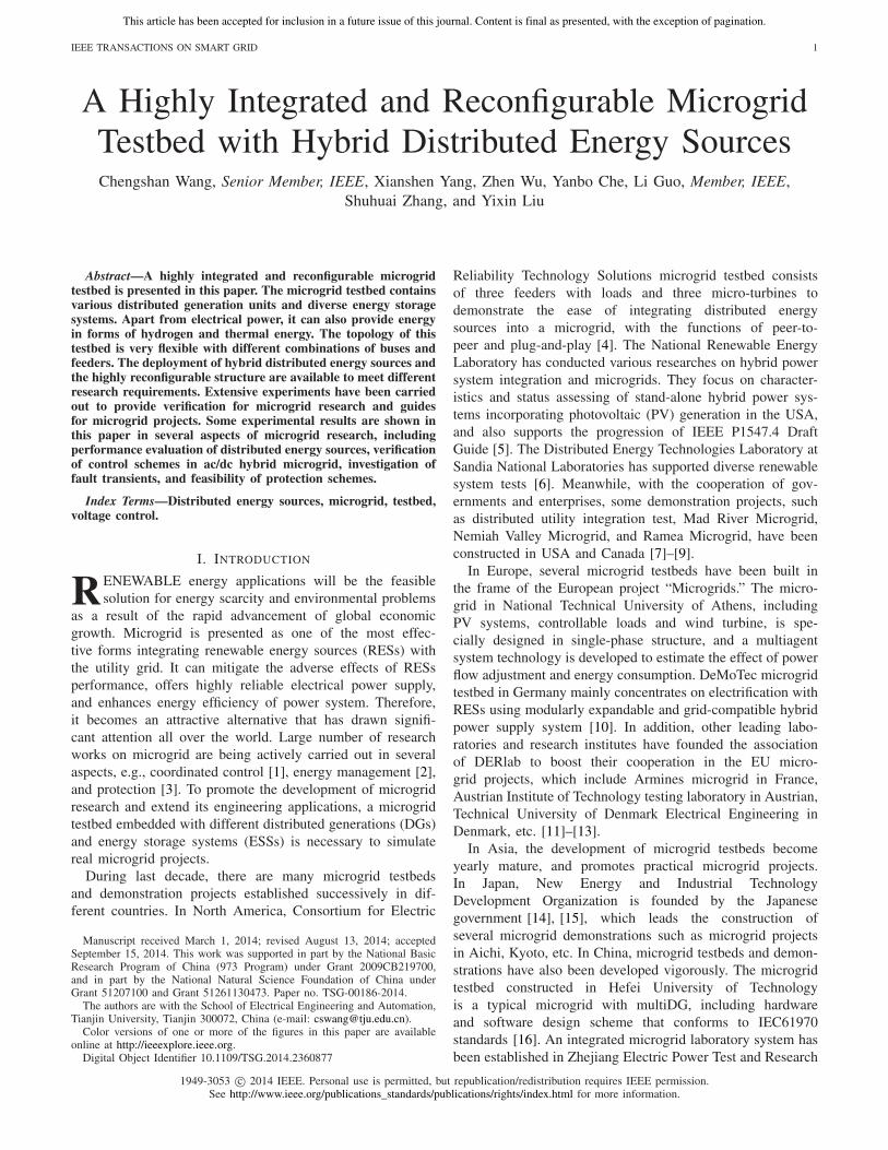
Fig. 2. Parts of DGs and ESSs in the TUMT. (a) Fixed PV. (b) Dual-axissolar tracking PV. (c) Horizontal-axis PMSG wind turbines. (d) Vertical-axisPMSG wind turbines. (e) CAES. (f) VRB. (g) Ultracapacitors. (h) Li-ionbattery. (i) Flywheel.
response time, are often used for minimizing powerspikes or power fluctuations.
The VRB system generates power by the redox reactionof vanadium, which consists of reservoirs and ion exchangemembranes. The data of stack voltage and state of charge canbe delivered via RS485 communication interface.
Li-ion battery ESS has functions of data collecting,temperature detecting, SoC calculating, current balancing,etc. The battery management system (BMS) integratedin the Li-ion battery ESS includes battery managementunits (BMU) in the bottom layer, battery cluster managementsystems (BCMS) in the middle layer and battery arrays man-agement system (BAMS) in the top layer. For the sake of theCMS dispatching, BMU in the bottom layer collects and deliv-ers data of each battery to the BCMS and BAMS successivelyin real time. Furthermore, the BMS is able to turn off the dcswitch in time for safety whenever temperatures or voltages ofbattery cells are beyond protection setting value continuously.
Unlike battery-based ESS which combines a large numberof battery cells in series and parallels, the CAES is comprisedof an air compressor, air tanks, a thermal storage unit (TSU),turbine, a small flywheel, and converters. Conventionally, airtanks, in which compressed air is stored, are maintained at fullcapacity by online compressor. When the CAES discharges, thehigh-pressure compressed air is constantly released from the airtanks, and drives the turbine after heated in TSU. Meanwhile,the flywheel in parallel connection uninterruptedly provideselectrical power until the turbine spins up.
Flywheel is a short-term ESS in which energy can be trans-formed between machinery and electricity rapidly. Once poweris demanded, the flywheel converts mechanical energy to elec-tricity with continuous declination of flywheel speed. Parts ofDGs and ESSs in the TUMT are shown in Fig. 2.
Additionally, there are some auxiliary devices available forwide range applications, such as active power filter, simulatedloads, fault simulator, battery testing equipment, transformer,
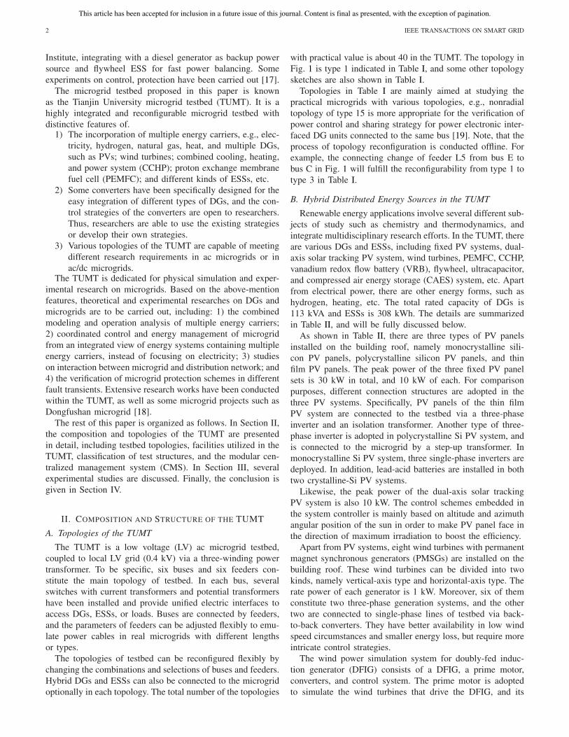
Fig. 3. Categories of tests. (a) Mode 1, single source in single bus.(b) Mode 2, multiple sources in single bus. (c) Mode 3, multiple sourcesin multiple buses.
and induction voltage regulator, etc. Specifically, active powerfilter is utilized to suppress microgrid testbed harmonics.Fault simulator generates a variety of precisely controllablefaults (i.e., fault duration, types, and location are controllable).Battery testing equipment enables programmable test schemesfor most of battery based ESS (e.g., life cycle, quality con-trol test). Transformer and induction voltage regulator playsan important role in testbed voltage adjustment under nor-mal working condition, and limits fault circuit current injectedfrom the grid when faults occur in the testbed.
C. Categories of Microgrid Tests
In the TUMT, characteristics and status of practical micro-grids can be simulated by the microgrid testbed in laboratoryenvironment. Numerous tests can be carried out with differ-ent combination and location of DGs and ESSs for specificresearch objectives, but they can be divided into three cate-gories considering some structural similarities among connec-tion modes. To be specific, these categories are (ranging fromsimple to complex): 1) Mode 1, single source in single busmode; 2) Mode 2, multiple sources in single bus mode; and3) Mode 3, multiple sources in multiple buses. Taking exam-ple for the topology of the TUMT in Fig. 1, the typical testcategories are shown in Fig. 3.
In Mode 1, only one DG or ESS is connected, and probablya set of simulated load is matched for it. This category of testsmainly focus on performance analysis and modeling of DGs orESSs, which are basic researches of microgrid. Fig. 3(a) is anexample of Mode 1, in which monocrystalline Si PV systemis connected to bus A. Based on the experiment results, PVmodels can be evaluated for microgrid transient analysis orpower dispatch.
This article has been accepted for inclusion in a future issue of this journal. Content is final as presented, with the exception of pagination.
WANG et al.: HIGHLY INTEGRATED AND RECONFIGURABLE MICROGRID TESTBED 5
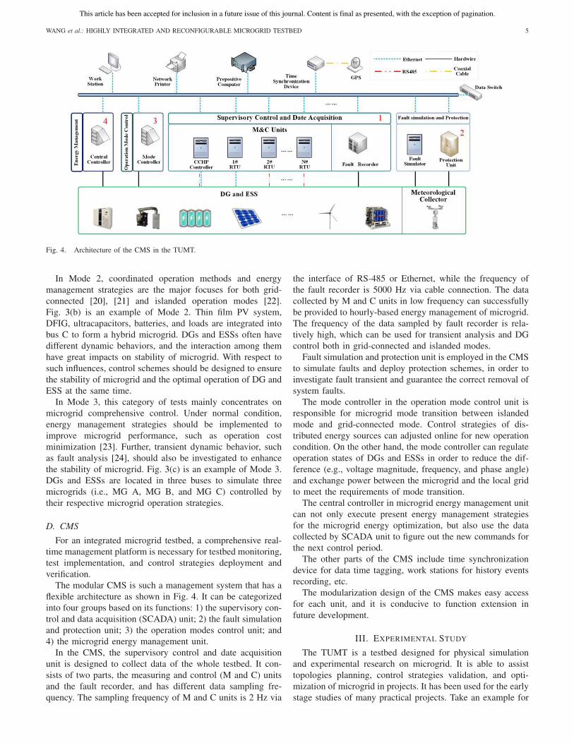
Fig. 4. Architecture of the CMS in the TUMT.
In Mode 2, coordinated operation methods and energymanagement strategies are the major focuses for both grid-connected [20], [21] and islanded operation modes [22].Fig. 3(b) is an example of Mode 2. Thin film PV system,DFIG, ultracapacitors, batteries, and loads are integrated intobus C to form a hybrid microgrid. DGs and ESSs often havedifferent dynamic behaviors, and the interaction among themhave great impacts on stability of microgrid. With respect tosuch influences, control schemes should be designed to ensurethe stability of microgrid and the optimal operation of DG andESS at the same time.
In Mode 3, this category of tests mainly concentrates onmicrogrid comprehensive control. Under normal condition,energy management strategies should be implemented toimprove microgrid performance, such as operation costminimization [23]. Further, transient dynamic behavior, suchas fault analysis [24], should also be investigated to enhancethe stability of microgrid. Fig. 3(c) is an example of Mode 3.DGs and ESSs are located in three buses to simulate threemicrogrids (i.e., MG A, MG B, and MG C) controlled bytheir respective microgrid operation strategies.
D. CMS
For an integrated microgrid testbed, a comprehensive real-time management platform is necessary for testbed monitoring,test implementation, and control strategies deployment andverification.
The modular CMS is such a management system that has aflexible architecture as shown in Fig. 4. It can be categorizedinto four groups based on its functions: 1) the supervisory con-trol and data acquisition (SCADA) unit; 2) the fault simulationand protection unit; 3) the operation modes control unit; and4) the microgrid energy management unit.
In the CMS, the supervisory control and date acquisitionunit is designed to collect data of the whole testbed. It con-sists of two parts, the measuring and control (M and C) unitsand the fault recorder, and has different data sampling fre-quency. The sampling frequency of M and C units is 2 Hz via
the interface of RS-485 or Ethernet, while the frequency ofthe fault recorder is 5000 Hz via cable connection. The datacollected by M and C units in low frequency can successfullybe provided to hourly-based energy management of microgrid.The frequency of the data sampled by fault recorder is rela-tively high, which can be used for transient analysis and DGcontrol both in grid-connected and islanded modes.
Fault simulation and protection unit is employed in the CMSto simulate faults and deploy protection schemes, in order toinvestigate fault transient and guarantee the correct removal ofsystem faults.
The mode controller in the operation mode control unit isresponsible for microgrid mode transition between islandedmode and grid-connected mode. Control strategies of dis-tributed energy sources can adjusted online for new operationcondition. On the other hand, the mode controller can regulateoperation states of DGs and ESSs in order to reduce the dif-ference (e.g., voltage magnitude, frequency, and phase angle)and exchange power between the microgrid and the local gridto meet the requirements of mode transition.
The central controller in microgrid energy management unitcan not only execute present energy management strategiesfor the microgrid energy optimization, but also use the datacollected by SCADA unit to figure out the new commands forthe next control period.
The other parts of the CMS include time synchronizationdevice for data time tagging, work stations for history eventsrecording, etc.
The modularization design of the CMS makes easy accessfor each unit, and it is conducive to function extension infuture development.
III. EXPERIMENTAL STUDY
The TUMT is a testbed designed for physical simulationand experimental research on microgrid. It is able to assisttopologies planning, control strategies validation, and opti-mization of microgrid in projects. It has been used for the earlystage studies of many practical projects. Take an example for
This article has been accepted for inclusion in a future issue of this journal. Content is final as presented, with the exception of pagination.
6 IEEE TRANSACTIONS ON SMART GRID
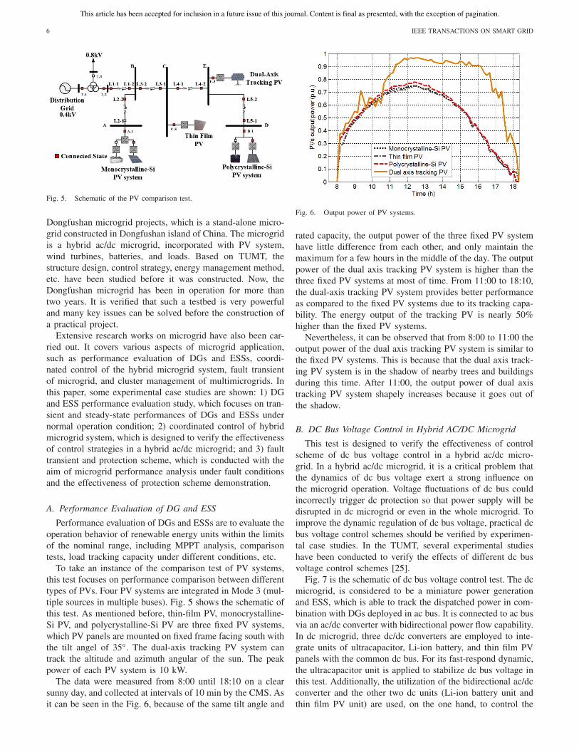
Fig. 5. Schematic of the PV comparison test.
Dongfushan microgrid projects, which is a stand-alone micro-grid constructed in Dongfushan island of China. The microgridis a hybrid ac/dc microgrid, incorporated with PV system,wind turbines, batteries, and loads. Based on TUMT, thestructure design, control strategy, energy management method,etc. have been studied before it was constructed. Now, theDongfushan microgrid has been in operation for more thantwo years. It is verified that such a testbed is very powerfuland many key issues can be solved before the construction ofa practical project.
Extensive research works on microgrid have also been car-ried out. It covers various aspects of microgrid application,such as performance evaluation of DGs and ESSs, coordi-nated control of the hybrid microgrid system, fault transientof microgrid, and cluster management of multimicrogrids. Inthis paper, some experimental case studies are shown: 1) DGand ESS performance evaluation study, which focuses on tran-sient and steady-state performances of DGs and ESSs undernormal operation condition; 2) coordinated control of hybridmicrogrid system, which is designed to verify the effectivenessof control strategies in a hybrid ac/dc microgrid; and 3) faulttransient and protection scheme, which is conducted with theaim of microgrid performance analysis under fault conditionsand the effectiveness of protection scheme demonstration.
A. Performance Evaluation of DG and ESS
Performance evaluation of DGs and ESSs are to evaluate theoperation behavior of renewable energy units within the limitsof the nominal range, including MPPT analysis, comparisontests, load tracking capacity under different conditions, etc.
To take an instance of the comparison test of PV systems,this test focuses on performance comparison between differenttypes of PVs. Four PV systems are integrated in Mode 3 (mul-tiple sources in multiple buses). Fig. 5 shows the schematic ofthis test. As mentioned before, thin-film PV, monocrystalline-Si PV, and polycrystalline-Si PV are three fixed PV systems,which PV panels are mounted on fixed frame facing south withthe tilt angel of 35◦. The dual-axis tracking PV system cantrack the altitude and azimuth angular of the sun. The peakpower of each PV system is 10 kW.
The data were measured from 8:00 until 18:10 on a clearsunny day, and collected at intervals of 10 min by the CMS. Asit can be seen in the Fig. 6, because of the same tilt angle and
Fig. 6. Output power of PV systems.
rated capacity, the output power of the three fixed PV systemhave little difference from each other, and only maintain themaximum for a few hours in the middle of the day. The outputpower of the dual axis tracking PV system is higher than thethree fixed PV systems at most of time. From 11:00 to 18:10,the dual-axis tracking PV system provides better performanceas compared to the fixed PV systems due to its tracking capa-bility. The energy output of the tracking PV is nearly 50%higher than the fixed PV systems.
Nevertheless, it can be observed that from 8:00 to 11:00 theoutput power of the dual axis tracking PV system is similar tothe fixed PV systems. This is because that the dual axis track-ing PV system is in the shadow of nearby trees and buildingsduring this time. After 11:00, the output power of dual axistracking PV system shapely increases because it goes out ofthe shadow.
B. DC Bus Voltage Control in Hybrid AC/DC Microgrid
This test is designed to verify the effectiveness of controlscheme of dc bus voltage control in a hybrid ac/dc micro-grid. In a hybrid ac/dc microgrid, it is a critical problem thatthe dynamics of dc bus voltage exert a strong influence onthe microgrid operation. Voltage fluctuations of dc bus couldincorrectly trigger dc protection so that power supply will bedisrupted in dc microgrid or even in the whole microgrid. Toimprove the dynamic regulation of dc bus voltage, practical dcbus voltage control schemes should be verified by experimen-tal case studies. In the TUMT, several experimental studieshave been conducted to verify the effects of different dc busvoltage control schemes [25].
Fig. 7 is the schematic of dc bus voltage control test. The dcmicrogrid, is considered to be a miniature power generationand ESS, which is able to track the dispatched power in com-bination with DGs deployed in ac bus. It is connected to ac busvia an ac/dc converter with bidirectional power flow capability.In dc microgrid, three dc/dc converters are employed to inte-grate units of ultracapacitor, Li-ion battery, and thin film PVpanels with the common dc bus. For its fast-respond dynamic,the ultracapacitor unit is applied to stabilize dc bus voltage inthis test. Additionally, the utilization of the bidirectional ac/dcconverter and the other two dc units (Li-ion battery unit andthin film PV unit) are used, on the one hand, to control the
This article has been accepted for inclusion in a future issue of this journal. Content is final as presented, with the exception of pagination.
WANG et al.: HIGHLY INTEGRATED AND RECONFIGURABLE MICROGRID TESTBED 7
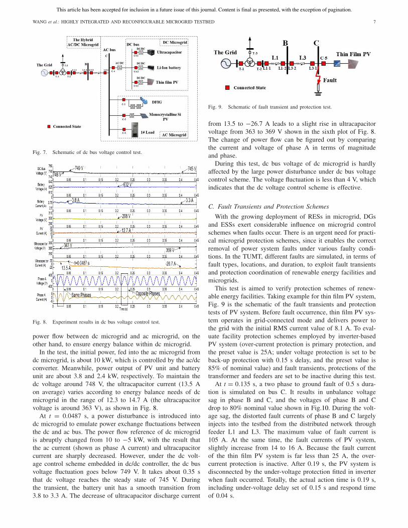
Fig. 7. Schematic of dc bus voltage control test.
Fig. 8. Experiment results in dc bus voltage control test.
power flow between dc microgrid and ac microgrid, on theother hand, to ensure energy balance within dc microgrid.
In the test, the initial power, fed into the ac microgrid fromdc microgrid, is about 10 kW, which is controlled by the ac/dcconverter. Meanwhile, power output of PV unit and batteryunit are about 3.8 and 2.4 kW, respectively. To maintain thedc voltage around 748 V, the ultracapacitor current (13.5 Aon average) varies according to energy balance needs of dcmicrogrid in the range of 12.3 to 14.7 A (the ultracapacitorvoltage is around 363 V), as shown in Fig. 8.
At t = 0.0487 s, a power disturbance is introduced intodc microgrid to emulate power exchange fluctuations betweenthe dc and ac bus. The power flow reference of dc microgridis abruptly changed from 10 to −5 kW, with the result thatthe ac current (shown as phase A current) and ultracapacitorcurrent are sharply decreased. However, under the dc volt-age control scheme embedded in dc/dc controller, the dc busvoltage fluctuation goes below 749 V. It takes about 0.35 sthat dc voltage reaches the steady state of 745 V. Duringthe transient, the battery unit has a smooth transition from3.8 to 3.3 A. The decrease of ultracapacitor discharge current
Fig. 9. Schematic of fault transient and protection test.
from 13.5 to −26.7 A leads to a slight rise in ultracapacitorvoltage from 363 to 369 V shown in the sixth plot of Fig. 8.The change of power flow can be figured out by comparingthe current and voltage of phase A in terms of magnitudeand phase.
During this test, dc bus voltage of dc microgrid is hardlyaffected by the large power disturbance under dc bus voltagecontrol scheme. The voltage fluctuation is less than 4 V, whichindicates that the dc voltage control scheme is effective.
C. Fault Transients and Protection Schemes
With the growing deployment of RESs in microgrid, DGsand ESSs exert considerable influence on microgrid controlschemes when faults occur. There is an urgent need for practi-cal microgrid protection schemes, since it enables the correctremoval of power system faults under various faulty condi-tions. In the TUMT, different faults are simulated, in terms offault types, locations, and duration, to exploit fault transientsand protection coordination of renewable energy facilities andmicrogrids.
This test is aimed to verify protection schemes of renew-able energy facilities. Taking example for thin film PV system,Fig. 9 is the schematic of the fault transients and protectiontests of PV system. Before fault occurrence, thin film PV sys-tem operates in grid-connected mode and delivers power tothe grid with the initial RMS current value of 8.1 A. To eval-uate facility protection schemes employed by inverter-basedPV system (over-current protection is primary protection, andthe preset value is 25A; under voltage protection is set to beback-up protection with 0.15 s delay, and the preset value is85% of nominal value) and fault transients, protections of thetransformer and feeders are set to be inactive during this test.
At t = 0.135 s, a two phase to ground fault of 0.5 s dura-tion is simulated on bus C. It results in unbalance voltagesag in phase B and C, and the voltages of phase B and Cdrop to 80% nominal value shown in Fig.10. During the volt-age sag, the distorted fault currents of phase B and C largelyinjects into the testbed from the distributed network throughfeeder L1 and L3. The maximum value of fault current is105 A. At the same time, the fault currents of PV system,slightly increase from 14 to 16 A. Because the fault currentof the thin film PV system is far less than 25 A, the over-current protection is inactive. After 0.19 s, the PV system isdisconnected by the under-voltage protection fitted in inverterwhen fault occurred. Totally, the actual action time is 0.19 s,including under-voltage delay set of 0.15 s and respond timeof 0.04 s.

This article has been accepted for inclusion in a future issue of this journal. Content is final as presented, with the exception of pagination.
8 IEEE TRANSACTIONS ON SMART GRID
Fig. 10. Microgrid protection test in the TUMT. Two phase to ground faulton bus C, 0.5 s duration, and voltage dip of 80% rate value.
The experimental results show transients behaviors ofinverter-based PV under a two-phase-fault to ground condi-tion. With cooperation of current and voltage protection, PVsystem can be quickly isolated from the grid when the faultoccurs.
IV. CONCLUSION
The TUMT is presented in this paper incorporating withDGs and ESSs of multiple energy carriers. With different com-binations of buses and feeders, there are various topologiesavailable to meet different research requirements. Three cat-egories are used for classification of microgrid tests on thebasis of the connection modes ranging from simple to com-plex. To manage this complex microgrid testbed effectively,the modular CMS with four functional groups has been builtto control the TUMT remotely.
The TUMT is designed for physical simulation and exper-imental research on microgrid. Extensive project simulationsand experiments involving different research fields have beencarried out. Dongfushan project and some experimental testsare shown in this paper. The continuous operation of theproject and results of the tests indicate that such a testbedis very powerful to conduct researches on major issues ofmicrogrid.
At present, the TUMT is well designed for accessing newunits and controllers readily. In order to improve the inter-operability and versatility for microgrid controllers, furtherresearches are being conducted such as the application ofIEC61850.
REFERENCES
[1] R. Majumder et al., “Improvement of stability and load shar-ing in an autonomous microgrid using supplementary droop con-trol loop,” IEEE Trans. Power Syst., vol. 25, no. 2, pp. 796–808,May 2010.
[2] F. Katiraei and M. R. Iravani, “Power management strategies for a micro-grid with multiple distributed generation units,” IEEE Trans. Power Syst.,vol. 21, no. 4, pp. 1821–1831, Nov. 2006.
[3] V. Salehi et al., “Laboratory-based smart power system, part II: Control,monitoring, and protection,” IEEE Trans. Smart Grid, vol. 3, no. 3,pp. 1405–1417, Sep. 2012.
[4] R. H. Lasseter et al., “CERTS microgrid laboratory test bed,” IEEETrans. Power Del., vol. 26, no. 1, pp. 325–332, Dec. 2010.
[5] J. Jonkman. (2010, Jun.). FAST User’s Guide, National RenewableEnergy Laboratory, Golden, CO, USA [Online]. Available:http://wind.nrel.gov/designcodes/simulatiors/fast/
[6] S. Gonzalez, S. Kuszmaul, and A. Ellis, “Long-term inverter operationdemonstration at Sandia National Laboratories,” presented at the 34thIEEE Photovoltaic Specialists Conference. (PVSC), Jun. 2009. [Online].Available: http://www.sandia.gov/media/online.htm
[7] M. L. Lazarewicz and J. A. Arseneaux, “Status of pilot projects usingflywheels for frequency regulation,” presented at the Power EngineeringSociety General Meeting, Montreal, QC, Canada, Jun. 2006. [Online].Available: http://ieeexplore.ieee.org/iel5/11204/36065/01709512.pdf
[8] S. Pelland, D. Turcotte, G. Colgate, and A. Swingler, “Nemiah Valleyphotovoltaic-diesel mini-grid: System performance and fuel saving basedon one year of monitored data,” IEEE Trans. Sustain. Energy, vol. 3,no. 1, pp. 167–175, Jan. 2012.
[9] J. F. Acevedo and M. T. Iqbal, “Communication system for theremote hybrid power system in Ramea Newfoundland,” presentedat the 23rd Canadian Conference on Electrical and ComputerEngineering (CCECE), Calgary, AB, Canada, May 2010. [Online].Available: http://www.engr.mun.ca/~tariq/
[10] M. Barnes et al., “Microgrid laboratory facilities,” in Proc. Int. Conf.Future Power Syst., Amsterdam, The Netherlands, 2005, pp. 1–6.
[11] A. G. de Muro et al., “Inverter interconnection tests performed in theLABEIN-Tecnalia microgrid involved in the DERlab round-robin testingactivity,” presented at the 10th International Conference on ElectricalPower Quality and Utilisation (EPQU), Lodz, Germany, Sep. 2009,pp. 1–6. [Online]. Available: http://www.der-lab.net
[12] M. Merdan, W. Lepuschitz, T. Strasser, and F. Andren, “Multi-agent system for self-optimizing power distribution grids,” pre-sented at the 5th International Conference on Automation, Roboticsand Applications (ICARA), Wellington, New Zealand, Dec. 2011,pp. 312–317. [Online]. Available: http://www.der-lab.net
[13] R. Garcia-Valle, Y. Guang-Ya, K. E. Martin, A. H. Nielsen,and J. Ostergaard, “DTU PMU laboratory development-testingand validation,” presented at the IEEE PES Innovative SmartGrid Technologies Conference Europe (ISGT), Gothenburg, Sweden,Oct. 2010, pp. 1–6. [Online]. Available: http://orbit.dtu.dk/fedora/objects/orbit:59646/datastreams/file_5190373/content
[14] S. Morozumi, “Micro-grid demonstration projects in Japan,” presentedat the Power Conversion Conference (PCC), Nagoya, Japan, Apr. 2007,pp. 635–642.
[15] S. Morozumi et al., “Distribution technology development and demon-stration projects in Japan,” presented at the IEEE Power Energy SocietyGeneral Meeting, Pittsburgh, PA, USA, Jul. 2008, pp. 1–7.
[16] M. Meiqin et al., “Testbed for microgrid with multi-energy gen-erators,” presented at the Canadian Conference on Electrical andComputer Engineering (CCECE), Niagara Falls, ON, USA, May 2008,pp. 000637–000640.
[17] B. Zhao, X. Zhang, and J. Chen, “Integrated microgrid laboratorysystem,” IEEE Trans. Power Syst., vol. 27, no. 4, pp. 2175–2185,Nov. 2012.
[18] B. Zhao et al., “Optimal sizing, operating strategy and operational expe-rience of a stand-alone microgrid on Dongfushan Island,” Appl. Energy,vol. 113, pp. 1656–1666, Jan. 2014.
[19] Y. W. Li and C.-N. Kao, “An accurate power control strategy forpower-electronics-interfaced distributed generation units operating in alow-voltage multibus microgrid,” IEEE Trans. Power Electron., vol. 24,no. 12, pp. 2977–2988, Dec. 2009.
[20] M. G. Villalva, J. R. Gazoli, and E. R. Filho, “Comprehensive approachto modeling and simulation of photovoltaic arrays,” IEEE Trans. PowerElectron., vol. 24, no. 5, pp. 1198–1208, May 2009.
[21] J. M. Carrasco et al., “Power-electronic systems for the grid integrationof renewable energy sources: A survey,” IEEE Trans. Ind. Electron.,vol. 53, no. 4, pp. 1002–1016, Jun. 2006.
[22] C. Wang, M. Liu, and L. Guor, “Cooperative operation and optimaldesign for islanded microgrid,” presented at the IEEE PES InnovativeSmart Grid Technologies (ISGT), Washington, DC, USA, Jan. 2012,pp. 1–8.
[23] M. A. Sofla and R. King, “Control method for multi-microgrid systemsin smart grid environment-stability, optimization and smart demand par-ticipation,” presented at the Innovative Smart Grid Technologies (ISGT),Washington, DC, USA, Jan. 2012, pp. 1–5.
This article has been accepted for inclusion in a future issue of this journal. Content is final as presented, with the exception of pagination.
WANG et al.: HIGHLY INTEGRATED AND RECONFIGURABLE MICROGRID TESTBED 9
[24] S. A. Gopalan et al., “Fault analysis of an islanded multi-microgrid,”presented at the IEEE Power and Energy Society General Meeting,San Diego, CA, USA, Jul. 2012, pp. 1–6.
[25] X. Li, C. Wang, L. Guo, and Y. Li, “A nonlinear disturbance observerbased DC bus voltage control for a hybrid AC/DC microgrid,” presentedat the IEEE International Conference on Energy Conversion Congressand Exposition (ECCE), Denver, CO, USA, Sep. 2013, pp. 1655–1662.
Chengshan Wang (SM’11) received the Ph.D.degree in electrical engineering from TianjinUniversity, Tianjin, China, in 1991.
He is currently a Professor with the Schoolof Electrical Engineering and Automation, TianjinUniversity. His current research interests include dis-tribution system analysis and planning, distributedgeneration system and microgrid, and power systemsecurity analysis.
Xianshen Yang was born in Hebei, China, in 1982.He received the B.S. degree in electrical engineer-ing from North China Electric Power University,Baoding, China, in 2008. He is currently pursu-ing the Ph.D. degree from the School of ElectricalEngineering and Automation, Tianjin University,Tianjin, China.
His current research interests include modelingand optimization of hybrid energy system.
Zhen Wu received the B.S. and Ph.D. degrees inelectric engineering from Tianjin University, Tianjin,China, in 2009 and 2014, respectively.
His current research interests include modelingand simulation of microgrids and energy storagesystem.
Yanbo Che received the B.S. degree in electricalengineering from Zhejiang University, Hangzhou,China, in 1993, and the M.S. and Ph.D. degreesin electrical engineering from Tianjin University,Tianjin, China, in 1996 and 2002, respectively.
He has been engaged in teaching and scientificresearch of power electronic technology and powersystems since 1996. He is currently an AssociateProfessor with the School of Electrical Engineeringand Automation, Tianjin University.
Li Guo (M’11) received the B.S. and Ph.D. degreesin electrical engineering from the South ChinaUniversity of Technology, Guangzhou, China, in2002 and 2007, respectively.
He was with Tianjin University, Tianjin, China, asa Post-Doctoral Fellow from 2007 to 2009. He hasbeen an Associate Professor with Tianjin Universitysince 2009. His current research interests includeoptimal planning and design of microgrid, the coor-dinated operating strategy of microgrid, and theadvanced energy management system.
Shuhuai Zhang received the B.S. degree in elec-trical engineering from Tianjin University, Tianjin,China, in 2012, where he is currently pursuing thePh.D. degree.
His current research interests include microgridcontrol, dc–dc converters, and soft switching.
Yixin Liu was born in Fujian, China, in 1989. Hereceived the B.S. degree from the School of ElectricEngineering and Automation, Tianjin University,Tianjin, China, in 2009, where he is currently pur-suing the Ph.D. degree with the Department ofElectrical Engineering and Automation.
His current research interests include the energymanagement system of microgrid, and control of thedistributed generations and microgrid.


![ARTICLE IN PRESSfaratarjome.ir/u/media/shopping_files/store-EN-1520504599-9025.pdf · fordability. Deep Convolutional Neural Networks (CNN), [16,17], are considered the more efficient](https://img.dokumen.tips/doc/110x75/5f44a94f755fa372611f9ea4/article-in-fordability-deep-convolutional-neural-networks-cnn-1617-are-considered.jpg)


![IEEE TRANSACTIONS ON POWER SYSTEMS 1 …faratarjome.ir/u/media/shopping_files/store-EN-1482738898-7266.pdf · cutset can be found by a depth-first-search [16] on . Definition 2](https://img.dokumen.tips/doc/110x75/5adb6ccc7f8b9a6d7e8df25f/ieee-transactions-on-power-systems-1-can-be-found-by-a-depth-rst-search-16.jpg)