Embed Size (px)
Citation preview

This article has been accepted for inclusion in a future issue of this journal. Content is final as presented, with the exception of pagination.
IEEE SYSTEMS JOURNAL 1
Investigation of Transmission Schemesfor Millimeter-Wave Massive
MU-MIMO SystemsYu Han, Student Member, IEEE, Haochuan Zhang, Member, IEEE, Shi Jin, Member, IEEE,Xiao Li, Member, IEEE, Rong Yu, Member, IEEE, and Yan Zhang, Senior Member, IEEE
Abstract—A massive multiuser multiple-input–multiple-output(MU-MIMO) system working at millimeter-wave frequencies is anew concept that has appeared in recent years. In such systems, thesparsity of the beamspace channel matrix makes the channel rankreduction and limited feedback realizable. Based on these prefer-able features, this paper introduces two kinds of beamspace trans-formation and exploits their corresponding beamspace characters.Then, the spatial division multiple access (SDMA) and the inter-ference suppression precoding are investigated separately. Consid-ering the advantages and disadvantages of these two traditionalschemes, the authors focus on the design of the limited-feedback-based multiuser transmission schemes for millimeter-wave massiveMIMO systems. An enhanced SDMA scheme is first proposed inthis paper, which utilizes the beamspace sparsity and overcomesthe challenges of channel information acquisition and interferencecontrol from a general perspective. Based on these, we analyze theinteruser interference condition and further propose a joint trans-mission scheme, which incorporates a double-precoding-basedSDMA and an interference suppression precoding. The perfor-mances of the proposed schemes are also evaluated via simulation,which show that high system sum-rate capacity could be achievedwith only low computational complexity and a small amount offeedback.
Manuscript received December 20, 2014; revised April 25, 2015 and July 3,2015; accepted August 18, 2015. The work of Y. Han, S. Jin, and X. Liwas supported by the National Natural Science Foundation of China (NSFC)under Grant 61531011, Grant 61571112, Grant 61450110445, Grant 61325004,and Grant 61222102; by the Natural Science Foundation of Jiangsu Provinceunder Grant BK2012021; by the International Science and Technology Cooper-ation Program of China under Grant 2014DFT10300; by the National Scienceand Technology Major Project of China under Grant 2013ZX03001032-004;by A Foundation for the Author of National Excellent Doctoral Dissertation ofChina (FANEDD) under Grant 201446; and by the Excellent Young TeachersProgram of Southeast University under Grant 2242015R30006. The work ofH. Zhang was supported by the National Natural Science Foundation of Chinaunder Grant 61501127. The work of R. Yu was supported in part by programsof the NSFC under Grant 61422201 and 61370159. The work of Y. Zhangwas supported in part by the Research Council of Norway through the Project240079/F20 and in part by the European Commission FP7 Project CROWNunder Grant PIRSES-GA-2013-627490.
Y. Han was with National Mobile Communications Research Laboratory,Southeast University, Nanjing 210096, China. She is now with the HuaweiShanghai Research Institute, Shanghai, China (e-mail: [email protected]).
H. Zhang and R. Yu are with Guangdong University of Technology,Guangdong 510006, China (e-mail: [email protected]; [email protected]).
S. Jin and X. Li are with the National Mobile Communications ResearchLaboratory, Southeast University, Nanjing 210096, China (e-mail: [email protected]; [email protected]).
Y. Zhang is with Simula Research Laboratory, 1364 Fornebu, Norway,and also with the Department of Informatics, University of Oslo, 0373 Oslo,Norway (e-mail: [email protected]).
Digital Object Identifier 10.1109/JSYST.2015.2481089
Index Terms—Massive multiple-input–multiple-output (MIMO),millimeter wave, multiuser transmission.
I. INTRODUCTION
CURRENTLY, most of the mobile communication systemswork at the frequencies between 300 MHz and 6 GHz,
which is generally considered to be the optimum band forcreating preferable broadcast conditions. However, with theincrease of user number and the diversification of data ser-vices, frequency band below 6 GHz tends to be overloaded.Frequencies between 6 GHz and 300 GHz become promisingand are full of exploiting potential [1] and [2]. Communicationsystems working at this band use millimeter waves as carriers,and they are named as millimeter-wave networks. In addition tofurther developing the frequency resources, exploiting spatialdegrees of freedom is another approach to meet the ever-growing demands of data rate and quality of service. By de-ploying multiple antennas at the transmitter and/or the receiver,a multiple-input–multiple-output (MIMO) system provides aneffective way to exploit the spatial degrees of freedom, andthis has become an important technique in modern wireless net-works [4]. Transmission methods for MIMO systems to achievespatial diversity, multiplexing gain, and capacity improvementhave been well investigated [5]–[7]. In multiuser MIMO (MU-MIMO) systems, the base station (BS) further exploits thespatial degrees of freedom and serves more than one useron the same time–frequency resource element [8] and [9]. Inrecent years, a new technique named massive MIMO has beenproposed and widely studied [10] and [11]. In massive MIMOsystems, the deployment of a large-scale antenna array resultsin much narrower transmit beams, along with an increase inbeamforming gain and a decrease in the interuser interference(IUI). In addition to these advantages, massive MIMO systemsalso face some challenges. For instance, the size of the antennaarray becomes much larger than that of a common MIMOsystem. Due to the wavelength-scaled distance between twoadjacent antenna elements, millimeter-wave networks enablethe deployment of large-scale antenna array within a limitedspace.
Massive MU-MIMO systems working at millimeter-wavefrequencies have attracted more and more attention. To mitigatethe problem of high-overhead channel state information (CSI)feedback, a joint spatial division and multiplexing multiuser
1932-8184 © 2015 IEEE. Personal use is permitted, but republication/redistribution requires IEEE permission.See http://www.ieee.org/publications_standards/publications/rights/index.html for more information.

This article has been accepted for inclusion in a future issue of this journal. Content is final as presented, with the exception of pagination.
2 IEEE SYSTEMS JOURNAL
transmission scheme for millimeter-wave channels was intro-duced in [13]. Based on the sparsity of the beamspace channelmatrix, a low-rank multiuser transmission scheme that performswell in IUI suppression was proposed in [14]. In the designof multiuser transmission schemes, IUI suppression is the keypoint and requires primary consideration [15], [16]. Generallyspeaking, there are two commonly used methods to suppressIUI, i.e., spatial division multiple access (SDMA) and inter-ference suppression precoding. However, both of them haveadvantages and disadvantages, and it is nontrivial to find ahybrid scheme that balances the two.
In this paper, we analyze the beamspace channel features andinvestigate the multiuser transmission schemes for millimeter-wave massive MIMO systems working in frequency divisionduplex (FDD) mode. The BS is deployed with a large-scaleuniform planar antenna array (UPA) according to the recent3GPP 3-D channel model recommendations. Multiple single-antenna users are served by the BS at the same time–frequencyresource element. The contributions of this paper are listed asfollows.
(1) This paper introduces two kinds of beamspace trans-formation, i.e., the broadcasting beamforming method and thededicated beamforming method, and investigates the sparsity ofthe beamspace channels. When exploring the beamspace char-acters, we discover the phase characters among the elements ofthe broadcasting beamspace channel vectors.
(2) This paper makes an enhancement to the well-knownSDMA scheme by exploring the beamspace sparsity to solvethe channel information acquisition and interference suppres-sion problem. For each user, the BS selects several beams thatcapture the channel’s main lobe, to approximate the originalhigh-dimensional channel, and transmits downlink dedicatedpilot signals directly on the reduced-rank channels. Then, eachuser estimates and feeds back its low-dimensional beamspacechannel vector to the BS. Finally, the BS rebuilds the phys-ical channels, creates the interference suppression precodingmatrix, and conducts data transmission. This enhanced SDMAscheme overcomes the difficulty in downlink CSI acquisitionfor massive MIMO FDD systems.
(3) This paper proposes a joint multiuser transmissionscheme, which incorporates a double-precoding SDMA anda zero-forcing (ZF)-precoding interference suppression. Thisjoint scheme is based on and improves the previous workpublished in [17]. According to whether the beam overlappingexists among different users, the user set is divided into twosubsets, i.e., a non-interference subset and an interferencesubset. The non-interference subset adopts a double-precoding-based SDMA scheme, and the interference subset adoptsan interference-suppression-precoding-based transmissionscheme. This incorporation utilizes the advantages of bothSDMA and interference suppression precoding and furtherreduces the feedback amount in FDD systems.
(4) Regarding [17], the new joint scheme introduces thebeamspace phase compensation precoding, which is motivatedby the discovery of the phase characters among the elementsof the broadcasting beamspace channel vectors. The precodingvector of each SDMA user is comprised of an inner multibeamselecting matrix and an outer phase compensating vector. This
Fig. 1. Single-cell millimeter-wave massive MIMO system.
scheme also can be viewed as an extension of [17] to the moregeneral and more complicated multipath propagation. This isnontrivial work since the analyzing method used in [17] wasonly faced to the single-path case.
Simulation results demonstrate that the enhanced SDMAscheme has excellent sum-rate performance, while the jointscheme reduces the feedback amounts greatly and requiresrelatively low-complexity computations.
Notation: In this paper, matrices and vectors are denoted byuppercase and lowercase boldface letters, respectively. We useI to denote the identity matrix. The superscripts (·)H , (·)T , and(·)∗ represent the conjugate-transpose, transpose, and conjugateoperations, respectively. Symbol E{·} represents the expecta-tion with respect to all random variables within the brackets.A⊗B is the Kronecker product of matrices A and B. Weuse | · | and ‖ · ‖ to denote taking absolute value and modulusoperations, respectively, and round(·) to represent rounding adecimal to its nearest integer.
II. SYSTEM MODEL
Consider a single-cell millimeter-wave massive MIMO sys-tem working in FDD transmission mode. The BS is located atthe cell center, which is deployed with UPA antenna array, andcommunicating with K single-antenna users simultaneously, asshown in Fig. 1.
A. Signal Model
In the downlink (i.e., from the BS to the users), the receivedsignal at user i can be expressed as
yi = hiwixi +∑k �=i
hiwkxk + ni (1)
where hi ∈ C1×Nt denotes the downlink channel vector of useri, Nt denotes the number of the antenna array elements atthe BS, wi ∈ C
Nt×1 is the precoding vector of user i, xi isthe transmit symbol for user i, and ni is zero-mean complexGaussian white noise with the variance of σ2.

This article has been accepted for inclusion in a future issue of this journal. Content is final as presented, with the exception of pagination.
HAN et al.: INVESTIGATION OF TRANSMISSION SCHEMES FOR MILLIMETER-WAVE MASSIVE MU-MIMO SYSTEMS 3
Denoting y = [y1, y2, . . . , yK ]T , we have
y = HWx+ n (2)
where H = [hT1 ,h
T2 , . . . ,h
TK ]
Tis the downlink channel ma-
trix, W = [w1,w2, . . . ,wK ] is the precoding matrix, x =[x1, x2, . . . , xK ]T is the transmit signal vector satisfyingE{xxH} = IK , and the precoded signal s = Wx satisfies thepower constrain E{sHs} ≤ P .
In Fig. 1 we can easily find out that, in a multiuser trans-mission system, some users are distributed far away fromeach other, while some users may be close to each other. Forinstance, users 5 and 6 are located very close, and severe IUIexists between them. In this case, there is a need for inter-ference control; otherwise, the performance of the multiusertransmission system will degrade significantly. Since precodingis one of the key techniques to control the interference indownlink transmission schemes, proper design of W becomesvery important.
B. Channel Model
Precoding design is based on the practical channel state ofthe millimeter-wave massive MIMO system. Here, we adoptthe spatial multipath channel model and write the downlinkphysical channel vector of user i as [18]
hi = βi,0at(Ωi,0) +
Np∑l=1
βi,lat(Ωi,l) (3)
where βi,0 and βi,l are the path factors of the line-of-sight(LOS) and non line-of-sight (NLOS) paths, respectively;Ωi,j =(θi,j , ϕi,j) represents the angles of departure (AoDs) of the jthpath; θi,j and ϕi,j are the downtilt and the azimuth, respec-tively.1 at(Ω) ∈ C1×Nt is the steering vector of UPA antennaarray with AoD Ω = (θ, ϕ), and it can be written as [12]
at(Ω) = at(θ, ϕ) = a(v)t (Θ)⊗ a
(h)t (Ξ)
a(v)t (Θ) =
1√N
(v)t
[1, e−j2πΘ, . . . , e
−j2π(N
(v)−1t
)Θ
]
a(h)t (Ξ) =
1√N
(h)t
[1, e−j2πΞ, . . . , e
−j2π(N
(h)−1t
)Ξ
](4)
where Θ = d(v)t /λ sin θ, Ξ = d
(h)t /λ cos θ sinϕ, Nt = N
(v)t ×
N(h)t , N (v)
t and N(h)t represent the number of UPA rows and
columns, d(v)t and d(h)t are the distances between two adjacent
antenna elements in a row and a column, and λ is the carrierwavelength. As mentioned earlier, for millimeter-wave systems,the primary existing broadcast path is LOS, and NLOS suffersfrom significant path loss; therefore, |βi,0| � |βi,l| for l ≥ 1.In the remainder of this paper, we neglect the NLOS paths andadopt the single-path model used in [14]. The physical channelmodel (3) becomes
hi ≈ βi,0at(Ωi,0) = βi,0at(θi,0, ϕi,0). (5)
1We use block fading to model the channel, where the channel fadingcoefficients keep constant during the transmission of a data block and changesindependently (randomly) in another block.
The following discussion will be based on this single-pathexpression. Since the NLOS paths still exist in practicalenvironment, we make detailed analysis about the multipathpropagation scenario in corresponding sections.
III. BASICS ON BEAMSPACE
This section introduces some basic information aboutbeamspace that will be needed in the following sections. Ingeneral, beamspace transformation is a powerful mathematicaltool for massive MIMO, which enables us to look at theLOS millimeter-wave channels in the so-called beamspaceperspective.
Considering the single antenna equipment of user i, thebeamspace transformation of its downlink channel vector canbe expressed as [19]
hi = hiU (6)
where hi ∈ C1×Nt is referred to as beamspace channel vector,and U ∈ CNt×Nt is the beamforming matrix expressed as
U =[bH(Ω1),b
H(Ω2), . . . ,bH (ΩNt
)]. (7)
The AoD value set {Ω1,Ω2, . . . ,ΩNt} contains Nt different
spatial directions; therefore, b (Ω1), . . . ,b (ΩNt) comprise a
set of basic 3-D beams. According to (6) and (7), the beamspacechannel vector hi is another linear presentation of hi andreflects the channel energy distribution on the basic beams. Inaddition, different choices of U contribute to different trans-formation results. Next, we introduce two kinds of beamspacetransformations, namely, broadcasting beamforming and dedi-cated beamforming.
A. Broadcasting Beamforming
As the name suggests, broadcasting beamforming is abeamspace transformation method applicable to all users’ spa-tial channel vectors under the same system deployment, re-gardless of each user’s AoD/angle of arrival (AoA). It choosesNt beams corresponding to Nt uniformly distributed spatialdirections to be the set of basic beams. The jth basic beam usedin the broadcasting beamforming matrix is
bDFT(Ωj) = a(v)t
(m
N(v)t
)⊗ a
(h)t
(n
N(h)t
)(8)
where j=mN(h)t +n, m=0, . . . , N
(v)t −1, n=0, . . . , N
(h)t −
1. These discrete Fourier transforming (DFT)-based beamsare orthogonal to each other and covers Nt fixed directionsindependent with any user channel, as shown in Fig. 2. If wedenote
V(v)DFT =
[a(v)t (0), a
(v)t
(1
N(v)t
), . . . , a
(v)t
(N
(v)t − 1
N(v)t
)]
V(h)DFT =
[a(h)t (0), a
(h)t
(1
N(h)t
), . . . , a
(h)t
(N
(h)t − 1
N(h)t
)](9)

This article has been accepted for inclusion in a future issue of this journal. Content is final as presented, with the exception of pagination.
4 IEEE SYSTEMS JOURNAL
Fig. 2. Nt orthogonal beams can be displayed in UPA topology, according to the azimuth and the downtilt. Beams in the same row have the same downtilt, andthose in a column have the same azimuth.
and substitute (9) into (7), we get the expression of the broad-casting beamforming matrix
Ubroa = V(v)DFT ⊗V
(h)DFT. (10)
Therefore, the beamspace channel of user i is written as
hbroa,i = hiUbroa. (11)
Single-path channel model (5) gives us freedom to exploitpotential mathematical regulars. The following proposition fur-ther points out the phase difference between adjacent elementsof hbroa,i.
Proposition 1: The phase difference between two row-adjacent elements of hbroa,i is ((N
(h)t − 1)/N
(h)t )π or −(π/
N(h)t ), and the phase difference between two column-adjacent
elements is ((N (v)t − 1)/N
(v)t )π or −(π/N
(v)t ).
Proof: According to the definition of beamspace channel,hbroa,i can be expressed as
hbroa,i = βi,0 · at(Ωi,0) ·[bHDFT(Ω1), . . . ,b
HDFT (ΩNt
)].
(12)
Denote the jth element of hbroa,i as hbroa,i,j , we can get that
hbroa,i,j = βi,0 · at(Ωi,0)bHDFT(Ωj) = βi,0 · a(v)t · a(h)t , (13)
where
a(v)t =
1
N(v)t
ejπ(N
(v)t −1
)Ψj · sin(πN
(v)t Ψj)
sin(πΨj),
a(h)t =
1
N(h)t
ejπ(N
(h)t −1
)Yj · sin(πN
(h)t Yj)
sin(πYj),
Ψj =mj
N(v)t
−Θi,0, Yj =nj
N(h)t
− Ξi,0. (14)
Substitute (14) into (13), then we get the analytical expression
hbroa,i,j = βi,0 ·1
Nt· ejπ
[(N
(v)t −1
)Ψj+
(N
(h)t −1
)Yj
]
·sin
(πN
(v)t Ψj
)sin
(πN
(h)t Yj
)sin(πΨj) sin(πYj)
. (15)
Assuming hbroa,i,j and hbroa,i,j+1 are two adjacent elementsin the same row, wherein Ψj = Ψj+1, Yj+1 − Yj = (nj+1 −nj/N
(h)t ) = 1/N
(h)t , then we get that
hbroa,i,j+1
hbroa,i,j
= ejπ
N(h)t
−1
N(h)t · sin(πYj) sin(πN
(h)t Yj+1)
sin(πYj+1) sin(πN(h)t Yj)
. (16)
In other words, for a beamspace channel vector of the broad-casting beamforming, the phase difference between two adja-cent elements in the same row is ((N
(h)t − 1)/N
(h)t )π. If the
sin(·) term is negative, the phase difference becomes ((N (h)t −
1)/N(h)t )π − π = −(1/N
(h)t )π. Accordingly, the phase differ-
ence between two adjacent elements in the same column is((N
(v)t − 1)/N
(v)t )π or −(1/N
(v)t )π. �
B. Dedicated Beamforming
Different from broadcasting beamforming, the dedicatedbeamforming method is based on a specific user channel and isapplicable to this channel uniquely. Derived from the statisticalCSI, dedicated beamforming performs better in precisely de-scribing the channel direction. To be specific, the transmit cor-relation matrix of user i and its eigenvalue decomposition are
Ri = E{hHi hi
}= ViΛiV
Hi , (17)
where2 Λi = diag{λi,1, λi,2, . . . , λi,Nt}, λi,1 ≥ λi,2 ≥ · · · ≥
λi,Ntare the eigenvalues of Ri, Vi = [vi,1,vi,2, . . . ,vi,Nt
],vi,j denotes the eigenvector corresponding to λi,j . Fordedicated beamforming, the beamforming matrix of user iis defined as Udedi,i = Vi [20], and the single path channelmodel enables the simplification for calculating the eigenmatrixVi. Substituting the single path channel model into (17), thetransmission correlation matrix of millimeter-wave massiveUPA antenna array can be written as
Ri = E
{∣∣βi,0
∣∣2 · aHt (Ωi,0) · at(Ωi,0)}. (18)
2It is worth noting that, although the instantaneous matrix hHi hi in (17)
has only rank one, averaging over a certain period of time (i.e., expectationimplemented via averaging) yields a higher rank matrix Ri with very highprobability.

This article has been accepted for inclusion in a future issue of this journal. Content is final as presented, with the exception of pagination.
HAN et al.: INVESTIGATION OF TRANSMISSION SCHEMES FOR MILLIMETER-WAVE MASSIVE MU-MIMO SYSTEMS 5
Fig. 3. Illustrations of the sparsity of |hbroa,i|2 and |hdedi,i|2, when
N(v)t ×N
(h)t = 8× 64. The graduated color from white to black represents
the increasing trend of channel energy distribution.
Since at(Ωi,0) = a(v)t (Θi,0)⊗ a
(h)t (Ξi,0), Ri in (18) can be
further written as Ri = R(v)i ⊗R
(h)i where
R(v)i = E
{∣∣∣β(v)i,0
∣∣∣2 · a(v)Ht (Θi,0)a(v)t (Θi,0)
},
R(h)i = E
{∣∣∣β(h)i,0
∣∣∣2 · a(h)Ht (Θi,0)a(h)t (Θi,0)
}(19)
are the vertical and horizontal transmit correlation submatriceswith eigenvalue decomposition
R(v)i = V
(v)i Λ
(v)i V
(v)Hi , R
(h)i = V
(h)i Λ
(h)i V
(h)Hi . (20)
Therefore, we can get that Vi = V(v)i ⊗V
(h)i . It’s worth
noting that the Kronecker product based docomposition of Ri
and that of Vi hold in single path propagation environments,while in multipath scenario they hold under some specialconditions [21]. In practical situations, the BS is horizontallydeployed with large numbers of antennas to enhance thespatial resolution, and when N
(h)t → ∞, V
(h)i ≈ V
(h)DFT.
Therefore, the dedicated beamforming matrix can berewritten as
Udedi,i = V(v)i ⊗V
(h)DFT. (21)
In this case, the beamspace channel of user i is expressed as
hdedi,i = hiUdedi,i. (22)
C. Approximate Beamspace Channel
According to the aforementioned properties of themillimeter-wave massive MIMO system, the downlink channelis usually narrow and strongly directional; therefore, thechannel’s main lobe captures only a small number of basicbeams, which contributes to the sparsity of the beamspacechannel [14]. Fig. 3 gives an example of |hbroa,i|2 and |hdedi,i|2for the 8 × 64 UPA. Obviously, the beamspace channel holdssparsity, and the channel energy is concentrated on a fewbeams. Therefore, we can approximate the original high-dimensional channel using these beams to reduce the channeldimension. Take the broadcasting beamforming for instance.Assume that indexbroa,i = {ibroa,1, ibroa,2, . . . , ibroa,Nb
} con-tains the indices of Nb largest elements of |hbroa,i|2, and
|hibroa,1 |2 ≥ |hibroa,2 |2 ≥ · · · ≥ |hibroa,Nb|2. In this case, we
approximate the beamspace channel as
h(a)
broa,i = hbroa,i ·Bbroa,i (23)
whereBbroa,i∈RNt×Nb is the beam selection matrix written as
Bbroa,i =[e(ibroa,1)Nt
, e(ibroa,2)Nt
, . . . , e(ibroa,Nb
)
Nt
]
e(j)Nt
=
⎡⎢⎣0, . . . , 0︸ ︷︷ ︸
j−1
, 1, 0, . . . , 0︸ ︷︷ ︸Nt−j
⎤⎥⎦T
. (24)
Similarly, for the dedicated beamforming case, the in-dices of Nb largest elements of |hdedi,i|2 are indexdedi,i ={idedi,1, idedi,2, . . . , idedi,Nb
}, and the approximate beamspacechannel is
h(a)
dedi,i = hdedi,i ·Bdedi,i (25)
where the beam selection matrix is expressed as
Bdedi,i =[e(idedi,1)Nt
, e(idedi,2)Nt
, . . . , e(idedi,Nb
)
Nt
]. (26)
In Fig. 3, we can also observe that Nb Nt; therefore, with
small-scaled h(a)
broa,i or h(a)
dedi,i, the challenges of computationcomplexity and CSI feedback in massive MIMO FDD systemsdisappear.
IV. SDMA SCHEME AND INTERFERENCE
SUPPRESSION PRECODING
Before moving forward to our proposal in Section V, we stillneed to introduce two components that are indispensable. Theseare SDMA and interference suppression precoding.
A. SDMA Scheme
As we know, the position of the user relative to the BSreflects the AoD of the LOS path, i.e., the channel direction.When the users are scattered far away from each other, theirchannel directions are significantly distinct from each other andare regarded to be spatial orthogonal to each other. Even if theirtransmit signals share the same time–frequency resource ele-ment, their transmission processes are almost independent fromeach other. This is the general idea of the SDMA scheme here.
Using the DFT beams introduced in Section III, the whole3-D space is segmented by Nt dominant directions. Any chan-nel direction can be approximately represented using severaldominant directions. If these user channels capture completelydifferent dominant directions, the BS can schedule them simul-taneously and the interference will be small enough, as shownin Fig. 4. For user i, having known its selected beam indicesindexbroa,i = {ibroa,1, ibroa,2, . . . , ibroa,Nb
}, the BS directlytransmits signals on its approximate broadcasting beamspacechannel. The received symbol at user i is
yi = h(a)
broa,ixi +∑k �=i
hbroa,i ·Bbroa,k · xk + ni
= hi ·Ubroa ·Bbroa,i · xi + n′i (27)

This article has been accepted for inclusion in a future issue of this journal. Content is final as presented, with the exception of pagination.
6 IEEE SYSTEMS JOURNAL
Fig. 4. General idea of SDMA scheme for millimeter-wave massive MIMOsystems. Assume that each user selects two DFT beams included in a dottedline. Overlap may exist between the beams selected by different users.
where xi,xk ∈ Nb×1 are the transmit signal vectors for useri and k, and n′
i contains the slight IUI and the noise. It iseasy to see that Ubroa ·Bbroa,i is only a precoding matrixwith the function of weakening sidelobe energy; hence, SDMAprecoding is equivalent to beam selection precoding.
In a crowded system, one dominant direction may be selectedby a few nearer users, which results in severe interference.Therefore, the SDMA scheme requires user scheduling oper-ation, i.e., only one of these mutually interfering users will bescheduled by the BS according to a certain rule. Commonlyused scheduling criteria include the maximum sum rate, theproportional fair, the round robin, etc. Take the maximum sum-rate scheduling as an example. The BS makes user selectionround by round. During each round, the BS picks out only oneuser who enhances the current multiuser system sum rate andadds it into the scheduled user set.
B. Interference Suppression Precoding
Interference suppression precoding is a technique widelyadopted in MU-MIMO systems. ZF precoding among the mostpopular precoding schemes decomposes the multiuser channelinto several orthogonal single-user subchannels and conductdata transmission on these subchannels independently.
Denote the precoding matrix on (2) for downlink ZF MU-MIMO systems as WZF. It is defined as
WZF = FP
F = HH(HHH)†
P = diag(√
P1, . . . ,√PK
)(28)
where (·)† represents the pseudoinverse [16]. Obviously HF =
HHH(HHH)†= I, and we have
hifj =
{1, i = j
0, i �= j
for F = [f1, f2, . . . , fK ]. In other words, the precoding vector ofuser i strengthens the channel energy of its own and suppressesthat of the others. P ∈ CK×K is used for transmit powerallocation, and one feasible example is the uniform allocationscheme
Pi =P
K · ‖fi‖2(29)
Fig. 5. Multiuser transmission process based on the proposed limited feed-back scheme.
where the total transmit power P is uniformly allocated toall users.
ZF precoding is a linear precoding method with decentthroughput performance; however, it requires full CSI at theBS and involves matrix multiplication and inversion. In massiveMIMO FDD systems, it is difficult for the BS to get the high-dimensional channel matrix, and the computation complexity isextremely high. This makes it difficult for ZF precoding to beapplied in massive MIMO FDD systems.
V. DESIGN OF LIMITED-FEEDBACK-BASED
TRANSMISSION SCHEMES
In massive MIMO systems, due to the high dimension ofthe channel matrix, difficulties exist in downlink orthogonalpilot sequences designing. In addition, the commonly appliedpilot-reuse method brings in significant pilot contamination andgreatly impacts the system performance. Fortunately, as wehave discussed, the channel vectors for massive MIMO systemsworking at millimeter-wave frequencies hold sparsity and canbe approximated by low-dimensional beamspace channels. Thismakes the design of pilot sequences possible and further en-ables decreasing feedback amount in FDD transmission mode.
A. Enhanced SDMA Scheme
We first propose an enhanced SDMA scheme for millimeter-wave massive MU-MIMO transmission systems. Both broad-casting and dedicated beamforming methods are applicablehere. Considering the existing interference among differentusers, we adopt the ZF-precoding-based transmission schemeand suppress IUI from a general perspective. The enhancedSDMA scheme operates according to the following steps, asshown in Fig. 5.
Step 1: Channel Sounding and Beam Selection: Users trans-mit uplink channel sounding signals, and then, the BS gets per-fect uplink CSI through channel sounding. It has been provedthat the statistical CSI is independent of the carrier wavelength,and reciprocity holds between the uplink and downlink statisti-cal CSI in millimeter-wave massive MIMO FDD systems [13].
This article has been accepted for inclusion in a future issue of this journal. Content is final as presented, with the exception of pagination.
HAN et al.: INVESTIGATION OF TRANSMISSION SCHEMES FOR MILLIMETER-WAVE MASSIVE MU-MIMO SYSTEMS 7
Considering the long-term feature of the AoD, we can applythe uplink beam selection result to the downlink transmissionprocess. Assume that the uplink channel vector of user i isgi ∈ CNt×1. Transform it into beamspace
gi = UHi gi (30)
where Ui is the previously introduced downlink beamformingmatrix for user i. After calculating |gi|2, we sort its elements indescending order, pick out the biggest Nb values, and get theircorresponding indices. Now, we know the selected beams andthe downlink beam selection matrix Bi.
Step 2: Pilot Transmission and Channel Estimation: Foreach user, the BS transmits the downlink dedicated pilot se-quence on the beams that it selects in step 1, i.e.,
yp,i = hi ·Ui ·Bi · pi + ni = h(a)
i · pi + ni (31)
where pi ∈ CNb×1 is the pilot signal that the BS sends touser i; pi and pj are orthogonal for i �= j. We can find thathi ·Ui ·Bi is only the approximate beamspace channel vector.Having received its dedicated pilot sequence, user i estimatesits approximate beamspace channel every fading block by
ˆh(a)
i = yp,i · p†i. (32)
Step 3: Feedback: Now, each user gets its reduced-rankchannel vector, and this vector contains the majority of thecomplete downlink CSI; therefore, it only needs to feedbackits estimated approximate beamspace channel vector to theBS. The total feedback amount in this step is K ·Nb complexnumbers.
Step 4: Precoding and Data Transmission: According to thereceived feedback values, the BS rebuilds the original high-dimensional physical channel vectors. For user i, we have
hi =ˆh(a)
i ·BiT ·UH
i . (33)
Having known the rebuilt physical channel vectors of all users,the BS generates the matrix
H =[hT
1 , hT
2 , . . . , hT
K
]T. (34)
As mentioned earlier, IUI is suppressed from a general per-spective. Substituting (34) into the expression of ZF precodingmatrix (28) and adopting the uniform power allocation scheme,the precoding matrix is given as
WZF = HH(HH
H)†·P, (35)
where Pi is calculated by (29). Finally, the BS implementsdownlink precoding and transmits the precoded signals toall users.
This enhanced SDMA scheme fully utilizes the preferablefeatures of millimeter-wave massive MIMO systems and con-tributes to a multiuser transmission strategy with good sum-rateperformance and low computation complexity. Moreover, thescheme is also applicable in multipath propagation scenarios,provided that the channel shows sparsity and can be reduced.However, each user must feedback its estimated low-rank chan-nel, which is a complex vector and costs a wide frequency bandin feedback link. Furthermore, the general ZF scheme neglects
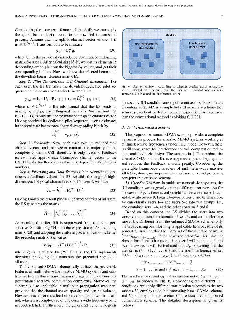
Fig. 6. User set division. According to whether overlap exists among thebeams selected by different users, the user set is divided into an non-interference subset and an interference subset.
the specific IUI condition among different user pairs. All in all,the enhanced SDMA is a simple but still expensive scheme thatachieves excellent performance, although it is less expensivethan the conventional method exploiting full CSI.
B. Joint Transmission Scheme
The proposed enhanced SDMA scheme provides a completetransmission process for massive MIMO systems working atmillimeter-wave frequencies under FDD mode. However, thereis still some space for interference control, computation reduc-tion, and feedback design. The scheme in [17] combines theidea of SDMA and interference suppression precoding togetherand reduces the feedback amount greatly. Considering thepreferable beamspace characters of millimeter-wave massiveMIMO systems, we improve the previous work and propose anew joint transmission scheme.
1) User Set Division: In multiuser transmission systems, theIUI condition varies greatly among different user pairs. As forthe case in Fig. 1, there is only slight IUI between users 1, 2, 3and 4, while severe IUI exists between users 5 and 6. Therefore,we can classify users 1–4 and users 5–6 into two groups, i.e.,one contains users 1–4, and the other contains 5 and 6.
Based on this concept, the BS divides the users into twosubsets, i.e., a non-interference subset U0 and an interferencesubset UI. Different from the enhanced SDMA scheme, onlythe broadcasting beamforming is applicable here because of itsgenerality. Assume that the index set of the selected beams is{indexbroa,i}i=1,...,K . If the beams selected for user i are notchosen for all the other users, then user i will be included intoU0; otherwise, it will be included into UI. Assuming that theuser set is U = {1, 2, . . . ,K} and the non-interference subsetis U0 = {u0,1, u0,2, . . . , u0,K0
}, then user u0,k satisfies
indexbroa,u0,k∩ indexbroa,i = ∅
i = 1, . . . ,K and i �= u0,k, k = 1, . . . ,K0. (36)
The interference subset UI is the complement of U0, i.e., UI =U − U0, as shown in Fig. 6. Considering the different IUIconditions, we apply different transmission schemes to the twosubsets. U0 employs a double-precoding-based SDMA scheme,and UI employs an interference-suppression-precoding-basedtransmission scheme. The detailed description is given asfollows.

This article has been accepted for inclusion in a future issue of this journal. Content is final as presented, with the exception of pagination.
8 IEEE SYSTEMS JOURNAL
Fig. 7. Spatial relations among the selected beams when Nb = 4. Centralred circle represents the strongest beam, and the surrounding orange circlesrepresent the potential substrong beams.
2) Double-Precoding-Based SDMA Scheme: Consideringthe non-overlapping feature among the beams selected by dif-ferent SDMA users, the BS transmits signals directly alongtheir corresponding approximate broadcasting beamspacechannels. As mentioned earlier, double precoding is usedin the SDMA scheme. The preliminary precoding vector isexpressed as
fSDMA = F1f2 (37)
where F1 ∈ CNt×Nb is the inner precoding matrix for roughpositioning, and f2 ∈ CNb×1 is the outer precoding vector formultibeam integration and beamspace phase compensation.Having known the selected beam indices of user u0,k, we definethe inner precoding as
Fu0,k,1 = Ubroa ·Bbroa,u0,k(38)
which is the beam selection precoding matrix introduced
previously. The phase character of h(a)
broa,u0,kreferred to as
Proposition 1 gives us a new idea of beamspace phase com-pensation, i.e., that we can design a codebook specialized forfu0,k,2. The lth codeword in the outer precoding codebook is
f(l)u0,k,2
=[1, ejφl,1 , ejφl,2 , . . . , ejφl,Nb−1
]H(39)
where φl,j+1 is the phase difference between the jth and the
first element of h(a)
broa,u0,k. Since user u0,k does not know its
selected beam index indexbroa,u0,k={u0,k,1, u0,k,2, . . . ,
u0,k,Nb}, this codebook is only created at the BS. When
Nb = 4, all the possible spatial relations among these selectedbeams are presented in Fig. 7, where the central red circlerepresents the strongest beam, and the orange circles representthe potential position of the remaining Nb − 1 substrongbeams. Assume that
mj = round
(u0,k,j − u0,k,1
N(h)t
)
nj = u0,k,j − u0,k,1 −mjN(h)t
j = 2, . . . , Nb, −2 ≤ mj ≤ 2, −2 ≤ nj ≤ 2. (40)
For codeword f(l)u0,k,2
, the value set of φl,j+1 is
{−Xj · π, c · π −Xj · π},
Xj =mj
N(v)t
+nj
N(h)t
, c =
{1, Xj > 0
−1, Xj < 0.(41)
Since the two elements in the φl,j+1 value set have oppositesigns, the positive one and the negative one are marked with 1and 0, respectively.
Having estimated the low-dimensional beamspace channel
approximation ˆh(a)
broa,u0,kin step 2, we turn it into
ˆh(eq)
broa,u0,k=
ˆh(a)
broa,u0,k.
ˆh(a)broa,u0,k,1
=[1, ejϑ1 , . . . , ejϑNb−1
](42)
where ˆh(a)broa,u0,k,1
is the first element of ˆh(a)
broa,u0,k. Since the
phase difference ϑj ∈ (−π, π] is predictable, here, we do thefollowing transformation:
ϑj
{> 0 → 1
< 0 → 0.(43)
That is, if ϑj is positive, we sign it by 1, else by 0. There-fore, (ϑ1ϑ2, . . . , ϑNb−1) is represented by an Nb − 1-bit 0/1sequence for simplicity. Then, we convert this binary 0/1sequence to a decimal number, i.e., 000, 001, 010, 111 areconverted to 0, 1, 2, 7, respectively, and this decimal number isfed back to the BS as the precoding matrix indicator (PMI). Instep 4, the BS converts this 1-bit PMI inversely to the originalNb − 1-bit 0/1 sequence, reverts the corresponding φj+1, andfinally settles the complete fu0,k,2.
3) Interference-Suppression-Precoding-Based Scheme:Given UI, we notice that, under proper user grouping, usersin the same group may not interfere with each other, whichmeans that we still have room to suppress the interference.Following this thread, a new algorithm is proposed, withthe maximum interference user group. If a user groupUM = {uM,1, uM,2, . . . , uM,KM
} satisfies the criteria thatany pair of users in UM , i.e., uM,i, uM,j ∈ UM , hold therelationship (uM,i, uM,j) or 〈uM,i, uM,j〉, this group is calleda maximum interference user group. Here, (uM,i, uM,j)represents direct correlation, which means that overlap existsbetween indexuM,i
and indexuM,j. 〈uM,i, uM,j〉 represents
indirect correlation, and it holds when both (uM,i, uM,k) and(uM,k, uM,j) exist. The indirect correlation can be multistep,according to the concept of maximum interference. Therefore,we can further divide UI into several maximum interferenceuser groups {U (s)
M }s=1,...,S . Since there is no interferenceamong different groups, we only need to suppress the innergroup interference with the following steps.
Having received the estimated approximate beamspace chan-nel vectors that user u
(s)M,i ∈ U
(s)M feeds back, the BS first
rebuilds its original physical channel
hu(s)
M,i
=ˆh(a)
broa,u(s)
M,i·BT
broa,u(s)
M,i
UHbroa. (44)

This article has been accepted for inclusion in a future issue of this journal. Content is final as presented, with the exception of pagination.
HAN et al.: INVESTIGATION OF TRANSMISSION SCHEMES FOR MILLIMETER-WAVE MASSIVE MU-MIMO SYSTEMS 9
Then, stack all the rebuilt physical channel vectors of groupU
(s)M = {u(s)
M,1, u(s)M,2, . . . , u
(s)M,Ks
} into a matrix, and get that
H(s)
M =[hT
u(s)
M,1, h
T
u(s)
M,2, . . . , h
T
u(s)
M,Ks
]T. (45)
We keep adopting ZF precoding as the means of interferencesuppression. As mentioned earlier, the precoding matrix iscalculated as
F(s)ZF,M = H
(s)H
M
(H
(s)
M H(s)H
M
)†(46)
where the ith column of F(s)ZF,M represents the preliminary
precoding vector of user u(s)M,i.
4) Power Allocation and Transmission Process: In the jointtransmission scheme, we still adopt the uniform allocationmethod, and the total transmit power P is uniformly allocatedto all the users, no matter which subset it belongs to. The finalprecoding matrix is calculated as
W = [f1, f2, . . . , fK ]P,
where fi is the preliminary precoding vector of user i which iscalculated in Subsection B Part 2 and 3.
Generally speaking, the nonuniform allocation methods arealso applicable to our joint transmission scheme. In practicalsituations, we can design proper power allocation methods,according to different performance requirements.
Based on the transmission process described in the previoussubsection, our proposed joint double-precoding-based SDMAand interference suppression precoding multiuser transmissionscheme operates as follows.
Step 1) Channel sounding, beam selection, and user sorting:The users transmit uplink channel sounding signalsto the BS, and the BS uses the sounding results tofind out the strongest beams for each user. Accordingto the indices of the selected beams, the BS classifieseach user into either U0 or UI.
Step 2) Pilot transmission, channel estimation and feedbackvalue calculation: For each user, the BS transmitsthe downlink dedicated pilot sequence on the beamsthat it selects. Having received the pilot sequence,each user estimates its approximate broadcasting
beamspace channel ˆh(a)
broa,i. Since the SDMA schemeis based on double precoding, users in U0 shouldcalculate the outer PMI.
Step 3) Feedback: The users in U0 feedback the PMI, whileusers in UI feedback their estimated approximatebroadcasting beamspace channel vectors.
Step 4) Precoding and data transmission: According to thereceived feedback values, the BS calculates the pre-coding vectors and finally transmits the precodedsignals to the two subsets, separately.
5) Extensibility to Multipath Propagation Scenarios: In thispaper, we limited our focus on millimeter-wave frequencycommunication, in which a typical coverage radius was shown,in the literature, to be less than 200 m. In this small coveragearea, the LOS component was proved to be more dominant
Fig. 8. In multipath propagation scenarios, the existence of NLOS pathsbrings in a bias to the phase difference value derived in the single-pathpropagation scenario.
than the NLOS components. However, according to the fieldmeasurement results presented in [1]–[3], [13], [22], and [23],the NLOS paths still exist and capture a small part of thechannel energy. Therefore, here, we will discuss whether thejoint scheme is applicable in multipath propagation scenarios.
Derived from the single-path channel model, the beamspacephasic relations referred to as Theorem 1 no longer hold, whichfurther challenges the outer precoding and its PMI calculationin the double-precoding-based SDMA scheme. Considering theNLOS paths, the jth element of huni,i is written as
hbroa,i,j = βi,0 · at(Ωi,0) · bHDFT(Ωj)
+
Np∑l=1
βi,l · at(Ωi,l) · bHDFT(Ωj). (47)
Then, it becomes difficult to derive the expression of the phasedifference between hbroa,i,j and hbroa,i,j+1. We use Fig. 8 toillustrate the beamspace phase difference under this multipathpropagation condition. The black solid lines represent threerow-/column-adjacent DFT beams. ΔΩ is only the value of thephase difference derived from the single-path channel model.However, in multipath propagation scenarios, the existence ofNLOS paths will bring in a bias to ΔΩ. For the case of poorNLOS scenarios, the bias is slight enough. The practical phasedifference ΔΩ1 is the angle between the pink dotted line andthe bottom black line, and we can still use ΔΩ to approximateΔΩ1. While in strong NLOS scenarios, the practical phasedifference is hard to predict. If the real value is ΔΩ2, it willnot be reasonable to approximate ΔΩ2 by ΔΩ.
Fortunately, it has been proved that, in millimeter-wavenetworks, the NLOS paths result in 15–40 dB greater pathloss than free-space LOS paths [3], and the expected num-ber of broadcast paths is not more than 4 [23]. We haveinvestigated the phasic feature by simulation. The numericalresults show that, in poor NLOS condition, the phase differencebetween two row-adjacent elements of hbroa,i floats almost
within (−(π/2N(h)t ), (π/2N
(h)t )) relative to the derived values
{((N (h)t − 1)/N
(h)t )π,−(π/N
(h)t )} in Proposition 1, and the

This article has been accepted for inclusion in a future issue of this journal. Content is final as presented, with the exception of pagination.
10 IEEE SYSTEMS JOURNAL
phase difference between two column-adjacent elements floatsalmost within (−(π/2N
(v)t ), (π/2N
(v)t )) relative to {((N (v)
t −1)/N
(v)t )π,−(π/N
(v)t )}, similar to what the pink dotted line
shows in Fig. 8. In other words, the beamspace phasic relationshold approximately in millimeter-wave networks. If we keepadopting the double-precoding-based SDMA scheme and usethe single-path values in Proposition 1, the outer precoding stillworks well, except for slight inaccuracy in phasic compensa-tion. However, for rich scattering environment and full-rankchannel models, the outer precoding of the SDMA scheme willnot be usable.
VI. PERFORMANCE AND NUMERICAL RESULTS
To evaluate the performance of the proposed enhancedSDMA scheme and the joint transmission scheme formillimeter-wave massive MIMO systems, we make computersimulations, and the numerical results are provided here. Thetwo proposed transmission schemes are represented as scheme 1and scheme 2 for short, and the broadcasting-beamforming- andthe dedicated-beamforming-based enhanced SDMA schemesare referred to as DFT scheme1 and dedicated scheme1, respec-tively. We focus on the downlink sum rate expressed as3
Rsum =
K∑i=1
log2(1 + SINRi) (48)
where the signal-to-interference-and-noise ratio (SINR) foruser i is calculated as
SINRi =|hiwi|2
K∑k=1,k �=i
|hiwk|2 + σ2
. (49)
We also investigate the performance of three additionalmultiuser transmission schemes for comparison, which are DFTunscheduled, dedicated unscheduled, and DFT SDMA+ZF. InDFT unscheduled and dedicated unscheduled schemes, the BSdirectly transmits signals to each user on the DFT or dedicatedbeams that it selects without employing user scheduling opera-tions. The DFT SDMA+ZF scheme is the previous joint schemeproposed in [17], where the inner beam selection precodingis solely implemented for SDMA users and the beamspacephase compensation is reduced. We regard the performance ofthese three schemes as the comparison baselines. Consider a500-m-radius cell in the millimeter-wave massive MIMO sys-tem. The users are uniformly distributed in the cell. Thesimulation parameters are listed in Table I.
Fig. 9 compares the system sum rate of these schemes whenSNR = 30 dB and Nb = 2/4. The performance of the twounscheduled schemes are poor, particularly for the dedicatedunscheduled scheme, where each user adopts a specific setof basic beams. This is because, without user scheduling orinterference control, beams selected by different users arehighly correlated. After dividing the user set into two sub-sets and applying interference suppression to the interference
3Equation (48) is an upper bound of the system sum rate. As an upper bound,it is reasonable to assume that user i knows perfectly hiwk for all k.
TABLE ISIMULATION PARAMETERS
Fig. 9. System sum-rate comparison when SNR = 30 dB and Nb = 2/4.
user subset, the DFT SDMA+ZF scheme brings in significantimprovement. If we further introduce the phase compensationconcept, i.e., our proposed scheme 2, the precoded transmitsignals can better match the beamspace channels and the systemsum rate increases greatly. Since the DFT scheme 1 utilizesmuch more channel information, it presents obvious superiorityover the scheme 2. The dedicated scheme1 further employs thededicated beamforming method, and it outperforms the DFTscheme1 and all the other schemes.
Fig. 10 gives the system sum-rate comparison of the sixschemes when K = 30 and Nb = 2/4. It is easy to find out that,as the SNR increases, the achieved system sum rate is improvedfor all these six schemes. The dedicated scheme 1 performsbest, while the DFT scheme 1 is slightly inferior. The scheme 2requires far less feedback and computation but still performswell. Meanwhile, when we raise Nb from 2 to 4, more usersare included into the interference user subset. Subsequently, theDFT SDMA+ZF scheme achieves much higher sum rate, whilethe two unscheduled schemes go backward instead. Therefore,interference control is essential to multiuser systems. However,with the expansion of the interference user subset, IUI sup-pression requires more complicated ZF precoding calculation.If we keep increasing K and Nb, the size of the interference

This article has been accepted for inclusion in a future issue of this journal. Content is final as presented, with the exception of pagination.
HAN et al.: INVESTIGATION OF TRANSMISSION SCHEMES FOR MILLIMETER-WAVE MASSIVE MU-MIMO SYSTEMS 11
Fig. 10. System sum-rate comparison when K = 30 and Nb = 2/4.
Fig. 11. System sum-rate comparison, when four NLOS paths exist and theenergy of each NLOS path is 5 dB/3 dB lower than the LOS path.
user subset will increase and the scheme 2 approaches the DFTscheme 1. In other words, both the proposed schemes performwell, and there should be a tradeoff between system sum rateand feedback and computation.
We further evaluate the extensibility of the outer precoding ofscheme 2 to multipath propagation scenarios. Consider the pre-viously mentioned poor NLOS environment, where only fourNLOS paths exist. Fig. 11 compares the sum-rate performanceof scheme 2 with the DFT SDMA+ZF scheme, when the energyof each NLOS path is 5 dB/3 dB lower than the LOS path. It canbe seen from the solid lines that the outer precoding still workswell. If the energy difference is reduced from 5 dB to 3 dB, theperformance of outer precoding becomes poor, and the systemsum rate decreases significantly due to the loss of beamspace
sparsity. In other words, our previous work is applicable insingle-path and weak multipath scenarios, which correspond tothe sparse channel networks.
VII. CONCLUSION
Millimeter-wave massive MIMO systems provide prefer-able conditions for multiuser transmission. In this paper, wehave investigated the beamspace characters under two trans-formations and gave the low-rank representation of beamspacechannel vectors. Due to the sparsity, we first proposed anenhanced SDMA scheme, which overcomes the difficultiesof downlink CSI feedback in massive MIMO FDD systemsand performs well in achieving high sum rate. Based on theenhanced SDMA scheme and the beamspace phasic relations,we further proposed a joint transmission scheme, which incor-porates a double-precoding-based SDMA and a ZF-precodinginterference suppression to reduce the feedback amount andcomputation complexity. Simulation results illustrated that bothschemes have excellent performance in achieving their cor-responding targets of sum-rate maximization or complexityreduction.
REFERENCES
[1] Z. Pi and F. Khan, “An introduction to millimeter-wave mobile broadcastsystems,” IEEE Commun. Mag., vol. 49, no. 6, pp. 101–107, Jun. 2011.
[2] T. S. Rappaport et al., “Millimeter wave mobile communications for 5Gcellular: It will work!” IEEE Access, vol. 1, pp. 335–349, May 2013.
[3] T. S. Rappaport, E. Ben-Dor, J. N. Murdock, and Y. Qiao, “38 GHzand 60 GHz angle-dependent propagation for cellular and peer-to-peerwireless communications,” in Proc. IEEE Int. Conf. Commun., Jun. 2012,pp. 4568–4573.
[4] A. Goldsmith, Wireless Communications. Cambridge, U.K.:Cambridge Univ. Press, 2005, pp. 270–288.
[5] J. Zhu, J. Liu, S. Barbarossa, X. She, and L. Chen, “Investigation on pre-coding techniques in E-UTRA and proposed adaptive precoding schemefor MIMO systems,” in Proc. 14th Asia-Pac. Conf. Commun., 2008,pp. 1–5.
[6] T. Yoo and A. Goldsmith, “On the optimality of multiantenna broad-cast scheduling using zero-forcing beamforming,” IEEE J. Sel. AreasCommun., vol. 24, no. 3, pp. 528–541, Mar. 2006.
[7] H. Halbauer, S. Saur, J. Koppenborg, and C. Hoek, “3D beamforming:Performance improvement for cellular networks,” Bell Labs Tech. J.,vol. 18, no. 2, pp. 37–56, Sep. 2013.
[8] J. Jose, A. Ashikhmin, P. Whiting, and S. Vishwanath, “Scheduling andpre-conditioning in multi-user MIMO TDD systems,” in Proc. IEEE Int.Conf. Commun., May 2008, pp. 4100–4105.
[9] H. Sun and W. Fang, “Multi-user scheduling and interference alignmentfor cooperative multi-cell downlink transmissions,” in Proc. IEEE Veh.Technol. Conf. Spring, Jun. 2013, pp. 1–5.
[10] T. L. Marzetta, “Noncooperative cellular wireless with unlimited numbersof base station antennas,” IEEE Trans. Wireless Commun., vol. 9, no. 11,pp. 3590–3600, Nov. 2010.
[11] E. Larsson, O. Edfors, F. Tufvesson, and T. L. Marzetta, “Massive MIMOfor next generation wireless systems,” IEEE Commun. Mag., vol. 52,no. 2, pp. 186–195, Feb. 2014.
[12] X. Lu, A. Tolli, O. Piirainen, M. J. Juntti, and W. Li, “Comparison ofantenna arrays in a 3-D multiuser multicell network,” in Proc. IEEE Int.Conf. Commun., Jun. 2011, pp. 1–6.
[13] A. Adhikary et al., “Joint spatial division and multiplexing for mm-wavechannels,” IEEE J. Sel. Areas Commun., vol. 32, no. 6, pp. 1239–1255,Jun. 2014.
[14] A. Sayeed and J. Brady, “Beamspace MIMO for high dimensional multi-user communication at millimeter-wave frequencies,” in Proc. IEEEGlobal Telecommun. Conf., Dec. 2013, pp. 3679–3684.
[15] J. Li, K. B. Letaief, Z. MA, and Z. Cao, “Spatial multiuser access withMIMO smart antennas for OFDM systems,” in Proc. IEEE Veh. Technol.Conf. Fall, Oct. 2001, vol. 3, pp. 1553–1557.
This article has been accepted for inclusion in a future issue of this journal. Content is final as presented, with the exception of pagination.
12 IEEE SYSTEMS JOURNAL
[16] Q. H. Spencer, A. L. Swindlehurst, and M. Haardt, “Zero-forcingmethods for downlink spatial multiplexing in multiuser MIMO chan-nels,” IEEE Trans. Signal Process., vol. 52, no. 2, pp. 461–471,Feb. 2004.
[17] Y. Han, S. Jin, X. Li, and Y. Huang, “A joint SDMA and interferencesuppression multiuser transmission scheme for millimeter-wave massiveMIMO systems,” in Proc. IEEE Int. Conf. Wireless Commun. SignalProcess., Oct. 2014, pp. 1–5.
[18] A. Sayeed, “Deconstructing multiantenna fading channels,” IEEE Trans.Signal Process., vol. 50, no. 10, pp. 2563–2579, Oct. 2002.
[19] D. Tse and P. Viswanath, Fundamentals of Wireless Communication.Cambridge, U.K.: Cambridge Univ. Press, 2005, pp. 311–323.
[20] C. Oestges and B. Clerckx, MIMO Wireless Communications: From Real-World Propagation to Space-Time Code Design. San Diego, CA, USA:Academic, 2010, pp. 83–85.
[21] D. Ying, F. W. Vook, T. A. Thomas, D. J. Love, and A. Ghosh, “Kro-necker product correlation model and limited feedback codebook designin a 3D channel model,” in Proc. IEEE Int. Conf. Commun., Jun. 2014,pp. 5865–5870.
[22] K. Haneda, C. Gustafson, and S. Wyne, “60 GHz spatial radio trans-mission: Multiplexing or beamforming?” IEEE Trans. Antennas Propag.,vol. 61, no. 11, pp. 5735–5743, Nov. 2013.
[23] M. R. Akdeniz et al., “Millimeter wave channel modeling and cellularcapacity evaluation,” arXiv preprint arXiv:1312.4921, 2013.
Yu Han (S’14) received the B.S. degree incommunications engineering from the HangzhouDianzi University, Hangzhou, China, in 2012 and theM.S. degree in communications and information sys-tems from the Southeast University, Nanjing, China,in 2015.
In May 2015, she joined the Huawei ShanghaiResearch Institute, Shanghai, China. Her researchinterests include massive multiple-input–multiple-output systems, millimeter wave, multiuser transmis-sion schemes, and beamforming techniques.
Haochuan Zhang (M’15) received the Ph.D. degreein communication and information systems fromthe Beijing University of Posts and Telecommunica-tions, Beijing, China, in 2011.
From 2011 to 2014, he was with Ericsson Re-search, Stockholm, Sweden. In 2014, he joined theFaculty of Guangdong University of Technology,Guangzhou, China, where he is currently an Asso-ciate Professor in the School of Automation. He haspublished more than 15 technical papers (mostly inIEEE journals and flagship conferences), and he also
holds 15 patents (in U.S., Europe, or China). His current research interestsinclude signal processing, system design, and performance analysis of wirelesscommunications.
Shi Jin (S’06–M’07) received the B.S. degree incommunications engineering from Guilin Universityof Electronic Technology, Guilin, China, in 1996; theM.S. degree from Nanjing University of Posts andTelecommunications, Nanjing, China, in 2003; andthe Ph.D. degree in communications and informa-tion systems from the Southeast University, Nanjing,in 2007.
From June 2007 to October 2009, he was a Re-search Fellow with the Adastral Park Research Cam-pus, University College London, London, U.K. He is
currently with the Faculty of the National Mobile Communications ResearchLaboratory, Southeast University. His research interests include space–timewireless communications, random matrix theory, and information theory.
Dr. Jin and his coauthors were recipients of the 2011 IEEE CommunicationsSociety Stephen O. Rice Prize Paper Award in the field of communicationtheory and the 2010 Young Author Best Paper Award from the IEEE SignalProcessing Society. He serves as an Associate Editor for the IEEE TRANS-ACTIONS ON WIRELESS COMMUNICATIONS, the IEEE COMMUNICATIONS
LETTERS, and IET Communications.
Xiao Li (S’06–M’10) received the Ph.D. degree incommunication and information systems from theSoutheast University, Nanjing, China, in 2010.
She then joined the School of Information Sci-ence and Engineering, Southeast University, whereshe has been an Associate Professor in informa-tion systems and communications since May 2014.From January 2013 to January 2014, she was aPostdoctoral Fellow at The University of Texas atAustin, Austin, TX, USA. Her current research inter-ests include massive multiple-input–multiple-output
(MIMO), 3-D beamforming, multiuser MIMO.Dr. Li was a recipient of the 2013 National Excellent Doctoral Dissertation
of China for her Ph.D. dissertation.
Rong Yu (S’05–M’08) received the Ph.D. degreefrom Tsinghua University, Beijing, China, in 2007.
After that, he joined the School of Electronic andInformation Engineering, South China University ofTechnology (SCUT), Guangzhou, China. In 2010,he joined the Institute of Intelligent InformationProcessing, Guangdong University of Technology(GDUT), Guangzhou, where he is currently a FullProfessor. He is the coinventor of over ten patentsand author or coauthor of over 70 internationaljournal and conference papers. His research interest
mainly focuses on wireless communications and networking, including cogni-tive radio, wireless sensor networks, and home networking.
Dr. Yu is a member of the Home Networking Standard Committee in China,where he leads the standardization work of three standards. He currently servesas the Deputy Secretary General of the Internet of Things (IoT) IndustryAlliance, Guangdong, China, and as the Deputy Head of the IoT EngineeringCenter, Guangdong, China.
Yan Zhang (SM’10) received the Ph.D. degreein electrical and electronics engineering from theNanyang Technological University, Singapore.
He is currently the Head of the Department ofNetworks at Simula Research Laboratory, Fornebu,Norway, and an Associate Professor (part time) withthe Department of Informatics, University of Oslo,Norway. His current research interest include wire-less networks and reliable and secure cyberphysicalsystems (e.g., healthcare, transport, smart grid, etc.).
Dr. Zhang is a Senior Member of the IEEE Com-munications and IEEE Vehicular Technology Societies. He serves as a Tech-nical Program Committee Member for numerous international conferences,including the IEEE International Conference on Computer Communications(INFOCOM), the IEEE International Conference on Communications (ICC),the IEEE Global Communications Conference (GLOBECOM), and the IEEEWireless Communications and Networking Conference (WCNC). He has beena recipient of seven Best Paper Awards. He serves as an Associate Editoror on the editorial board of a number of well-established scientific interna-tional journals, e.g., Wiley Wireless Communications and Mobile Computing(WCMC). He also serves as the Guest Editor for the IEEE TRANSACTIONS
ON INDUSTRIAL INFORMATICS, the IEEE COMMUNICATIONS MAGAZINE,the IEEE WIRELESS COMMUNICATIONS, and the IEEE TRANSACTIONS ONDEPENDABLE AND SECURE COMPUTING. He has chair positions in a numberof conferences, including the IEEE International Symposium on Personal,Indoor and Mobile Radio Communications (PIMRC) 2016, the IEEE ConsumerCommunications and Networking Conference (CCNC) 2016, the Wireless In-ternet Conference (WICON) 2016, the IEEE International Conference on SmartGrid Communications (SmartGridComm) 2015, and the IEEE InternationalConference on Cloud Computing Technology and Science (CloudCom) 2015.