Embed Size (px)
Citation preview
IEEE SPM MAGAZINE, VOL. 34, NO. 5, SEPTEMBER 2017 1
High Dynamic Range Imaging TechnologyAlessandro Artusi, Thomas Richter, Touradj Ebrahimi, Rafał K. Mantiuk,
IN this lecture note, we describe high dynamic range(HDR) imaging systems; such systems are able to represent
luminances of much larger brightness and, typically, also alarger range of colors than conventional standard dynamicrange (SDR) imaging systems. The larger luminance rangegreatly improve the overall quality of visual content, makingit appears much more realistic and appealing to observers.HDR is one of the key technologies of the future imagingpipeline, which will change the way the digital visual contentis represented and manipulated today.
I. PREREQUISITES
Essential knowledge of linear algebra, image/signal process-ing and computer graphics is desirable. The basic aspects ofHigh Dynamic Range (HDR) imagery are required for the fullcomprehension of this lecture note. The readers are invitedto consult [1] for acquiring this basic know-how before toproceed with the reading of this lecture note.
II. RELEVANCE
Due to the availability of new display and acquisitiontechnologies, interest in HDR increased significantly in thepast years. Camera technologies have greatly evolved pro-viding high quality sensors that generate images of higherprecision and less noise; the market offers now displays thatare able to reproduce content with higher dynamic range,peak luminance and color gamut. These advances are openinga large number of applications that span from broadcastingto cinema, manufacturing industry to medical. This is alsodemonstrated by activities taking place nowadays within thestandardization communities, i.e., JPEG, MPEG and SMTPE.New standards have been created for still HDR images, i.e.,ISO/IEC 18477 JPEG XT [2], others are under development.All these activities are largely driven by industry, a strongindication that business cases around HDR will emerge in thenear future.
III. PROBLEM STATMENT AND SOLUTION
A. Problem Statment
The problem to be solved consists of the development of animaging and video system pipeline capable of representing awider range of luminance and colors values compared to thetraditional, standard dynamic range (SDR) system pipeline.The idea is to design a complete system, which incorporatesacquisition, storage, display and evaluation subsystems, asshown in Figure 1.
Real Scene
CG Modeling
HDR Camera
CG engine
LDR Camera
Encoding-Decoding
Observer 1 Observer 2
Objective metric
Native Visualization
Tone Mapping
HDR Display
LDR Display
Subjective
Acquisition Storage/Compression Display
HDR Quality Metrics
Viewing Conditions 1
Viewing Conditions 2
Fig. 1. HDR imaging pipeline: acquisition (greyish), storage (violet), display(yellowish) and evaluation (greenish).
B. Solution
1) Acquisition: Two major ways exist to generate HDRcontent, either generating scene through computer graphicstools or through the acquisition of real world scene with acamera. Rendering pipelines for computer-generated graphicsintegrate tools such as physically-based lighting simulationsthat use physical-valid data of the scene and the environment,i.e., light sources and object materials. The models used thereare capable of simulating physically plausible behavior of thelight of the scene within a specific environment and generateplausible images from an abstract scene description.
The second method acquires HDR images from real-wordscenes; today, high quality digital single-lens reflex (DSLR)cameras are available with sensors capable of capturing 12-to-16-bits per color channel. However, many portable devices,such as mobile phones and lower quality digital cameras areequipped with cheaper, lower performing hardware whoseprecision is limited to 10 bits or even lower.
For such a device, only a small subset of the availabledynamic range of the scene can be captured, resulting inoverexposed and underexposed areas of the acquired image.To overcome this limitation, one can capture different portionsof the dynamic range of the scene by varying the expo-sure time. The resulting images are then first registered, i.e.aligned to each other, before a camera response function isestimated from them. This function describes, parametrizedby the exposure time, how luminances received by the sensorare mapped to pixel values; its inverse allows to estimatephysical quantities of the scene from the acquired images.Finally, a weighted average over the pictures generates anHDR image [3]. The selected weights indicate the contributionof each frame at a given position to the final HDR samplevalue. An example of multi-exposure approach is depicted in
DOI: 10.1109/MSP.2017.2716957 ˜ c©2017 IEEE.
arX
iv:1
711.
1132
6v1
[cs
.GR
] 3
0 N
ov 2
017
IEEE SPM MAGAZINE, VOL. 34, NO. 5, SEPTEMBER 2017 2
Fig. 2. Multi-exposure approach used to capture an HDR image - (left) threeimages taken with three different exposure times t1, t2 and t3, with thedifferent portions of the dynamic range of the scene captured by the exposuretime ti - (right) the reconstructed HDR image. The reconstructed HDR imageis tone mapped for display purposes.
Figure 2; here three images of the same scene were taken,varying the exposure time. A (tone mapped) version of theresulting HDR is also depicted. A typical problem of the multi-exposure method is the misalignment of the images, either dueto movements in the scene or by the camera itself [4]. Mergingsuch images without further processing results in ghostingartifacts in the HDR output. Here below, such defects can beclassified as follows:
• Global misalignment due to camera motion, e.g. cameramovement or rotation. This type of misalignment affectsall pixels of the image causing ghost artifacts that can beremoved through image registration.
• Local misalignment due to moving objects in the scene,only affecting portions of the image. Such defects arise ifthe time between the individual exposures is larger thanthe typical time within which an object moves in thescene. For example, some objects may be occluded inone of the images, but are visible in others.
• Local and Global misalignments combining the twoprevious types. A typical example is that of a camerathat follows a free path, acquiring a scene composed ofdynamic objects.
2) Storage and Compression: A naıve analysis of HDRimages reveals that uncompressed HDR data would typicallyrequire four times more storage capacity than SDR data.Clearly, this view is oversimplifying the situation, but itshould at least indicate the need for a data format that ismore compact. Various better alternatives exist in the field,amongst them half-float (as used by OpenEXR), RGBE,LogLuv encoding, and representation of sample values in aperceptually uniform color space through an electro-opticaltransfer function (EOTF). All these convert a direct, floatingpoint representation into a more efficient data format thatrequires less bits, while still providing a higher dynamic rangeand more precision than an SDR format.
If the precision of the HDR format is not sufficient, thenquantization defects such as banding will become visible.
We now discuss a selection of popular HDR formats. Half-float precision is a compact representation for floating pointvalues where one bit is used for the sign, 5 bits for theexponent and 10 bits for the mantissa. The advantage that thehalf-float representation is offering is that it is as flexible asthe regular single precision floating point format at half of the
storage cost. However, since the maximum value representableby this format is 65535, sample values should be calibrated bya common scale factor, i.e., represented in “relative radiance”to be able to represent the full dynamic range in the image.
The RGBE format takes advantage of the fact that the colorcomponents of an RGB image are highly correlated and thatthey have usually very similar magnitude. RGBE thus onlystores one common scale factor for all three components inthe form of an exponent E, and the individual channels arejointly scaled by E as follows:
Re = b256R
2E−128c, (1)
for G and B the same equation applies. The b.c denotesrounding down to the nearest integer. E is the commonexponent that is encoded together with the RGB mantissas,resulting in a 32-bit per pixel representation.
E = dlog2(max(R,G,B)) + 128e, (2)
where d.e denotes rounding up to the next integer.A drawback of RGBE pixel encoding is that it cannot
represent negative samples values, i.e., colors that are outsideof the triangle spanned by the primary colors of the underlyingRGB color space. A possible remedy is to code colors in theXYZ color space taking only positive numbers by definition,then giving rise to the XYZE encoding.
In both cases, however, errors are not uniformly distributedperceptually speaking, a problem that is partially solved bythe LogLuv encoding. There, the luminance is coded logarith-mically in one sign bit, 15 mantissa bits and another 16 bitsto encode the chroma values ue and ve.
Logarithmic encoding of luminance values is a commontrick used in many HDR encodings: When the same magnitudeof distortion is introduced in low and high luminance imageregions, one finds that artifacts will be more visible in lowluminance regions as human vision follows approximately alogarithmic law — this is also known as Weber’s Law in theliterature.
However, more accurate models of human vision exist thatmap physical luminance (in nits, i.e., candela per square meter)into the units related to the just-noticeable-differences (JNDs).Such a mapping, namely from perceptually uniform samplespace to physical luminance, is also denoted as electro-opticaltransfer function ( EOTF). Studies have shown that under sucha mapping 10 to 12 bits are sufficient to encode luminancesbetween 10−4 to 108 nits without visible banding.
HDR file formats that are making use of these HDR pixelsrepresentation have been proposed, and the three most widelyused are Radiance HDR, the Portable File Format (PFM) andOpenEXR. Radiance HDR, indicated by the file extension.hdr or .pic, is based on RGBE or XYZE encoding, plusa minimal header. A very simple run-length coding over rowsis available.
PFM is part of the “portable any map” format, and is indi-cated by the .pfm extension. The header indicates the numberof components and a common scale factor of all sample values;the sign of the scale factor denotes the endianness of the

IEEE SPM MAGAZINE, VOL. 34, NO. 5, SEPTEMBER 2017 3
encoding. The actual image pixels are encoded as RGB triplesin IEEE single precision floating point.
OpenEXR uses as file extension .exr, and it has beendeveloped by Industrial Light and Magic in the 2002, alongwith open source libraries. Due to its high adoption it hasbecome the de-facto standard file format for HDR images,especially in the cinema industry. This file format supportsthree pixel encoding formats: half-float (16-bit float), 32-bitfloat and 32-bit integer. It also includes various lossy andlossless image compression algorithms.
We recently see the adoption of HDR technologies intoproducts such as cameras with improved sensors, displaysproviding higher dynamic range and/or larger color gamut.Unfortunately, interoperability at device level is still at its in-fancy, making it difficult to exchange images between variousdevices, or various vendors which try to lock-in customersthrough proprietary formats [2].
As for images, two international standards are already avail-able that support HDR content, namely ISO/IEC 15444, ITU-TT.800 JPEG 2000 and ISO/IEC 29199, ITU-T T.832 JPEG XR.Despite the fact that they support lossless compression, theirlimited adoption by the market may be correlated with theirlack of backward compatibility with existing JPEG ecosys-tem [5]. Industry players are typically reluctant to changetechnology in their production pipeline to cope with adoptionof newly established standards. A migration path from existingto new solutions, allowing a gradual transition from old to newtechnology helps them to keep the investments low.
To address this issue, the Joint Photographic Experts Group(JPEG) formally known as ISO/IEC JTC1/SC29/WG1, beganin the 2012 the standardization of a new standard technologycalled ISO/IEC 18477 JPEG XT [2]. The JPEG XT imagecoding system is currently organized into nine parts that definethe baseline coding architecture (the legacy JPEG codestream8-bit mode), an extensible file format specifying a commonsyntax for extending the legacy JPEG, and application of thissyntax for coding integer or floating point samples between 8and 16 bits precision [2].
This coding architecture is then further refined to enablelossless and near-lossless coding, and is complemented byan extension for representing alpha-channels [2]. Due to
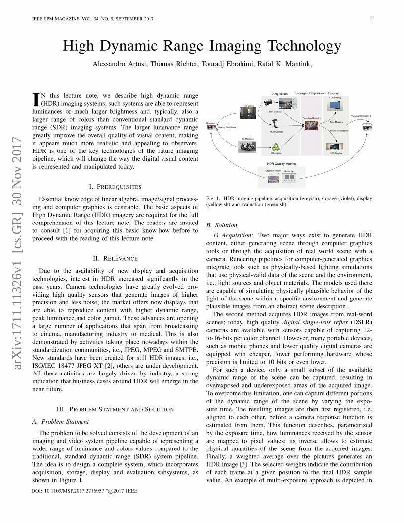
Fig. 3. The simplified decoding workflow for JPEG XT standard[5].B is the base layer and is always represented as a JPEG codestreamwith 8-bit per sample. E is the extension layer that used in conjunctionwith B allows the reconstruction of the HDR image.
its flexible layered structure, the JPEG XT capabilities canbe extended into novel applications such as omnidirectionalphotography, animated images, structural editing as well asprivacy and security that are under examination and develop-ment [6].
In practice, JPEG XT can be seen as a superset of the 8-bitmode JPEG where existing JPEG technology is re-used when-ever possible; this, in particular, allows to encode an HDRimage purely on the basis of legacy JPEG implementations.JPEG XT is a two layered design, of which the first layerrepresents the SDR image. It is encoded in JPEG, with 8-bitsper sample in the ITU BT.601-7 RGB color space (base layerB), see Figure 3. The extension layer E includes the additionalinformation to reconstruct the HDR image starting from thebase layer B.
Concerning video compression, some recent standards areproviding options to encode video in high bit precision, i.e.,up to 12 bits for ISO/IEC 14496-2 and ISO/IEC 14496-10AVC/H.264. These modes are defined in the profile FidelityRange Extensions (FRExt), and for ISO/IEC 23008-2 ITU-T-H.265 (HEVC) in the Format Range Extension (RExt).
The H.264/AVC extensions build upon an EOTF that coversa dynamic range of up to 2.5 magnitudes; while sufficient forconsumer applications, this is a limitation for typical HDRcontent.
H.265/HEVC recently integrated a transfer function forHDR video content that pre-quantizes data to a 10 or 12 bitdomain which is then taken as input by the HEVC encoder.This EOTF, denoted as ST2084 — Hybrid Log-Gamma — isdesigned for luminances up to 10, 000 nits. Finally, guidelineson how to encode HDR video content with HEVC, have beenprovided in ISO/IEC 23008-14 and 15.
Similar to JPEG XT, a backward compatible solution forHDR video encoding has been presented by Mantiuk etal.[7]. Recently a signaling mechanism to support backwardcompatibility, has been integrated into the HEVC standard(ISO/IEC NP TR 23008-15). The backward-compatibility isachieved as in the case of HDR still image encoding describedabove. A base layer encodes the SDR frames, and an extensionlayer hidden from the base includes the necessary informationto extend the dynamic range. To improve encoding perfor-mance, the redundancy information is minimized through thedecorrelation between the SDR and HDR streams, achievinga reduction in size of the HDR stream to about 30% of thesize of the SDR stream. Invisible noise reduction is also usedto remove details that cannot be seen in the residual streamprior to encoding.
3) Display: The native visualization of HDR content islimited by the physics of the display. Despite the fact that thecurrent technology on the market can guarantee high contrastratio, this is achieved by lowering the black level. However,the peak luminance remains limited, restricting the availabledynamic range for bright images. Even with enhanced contrast,many display panels offer only a limited precision of 8 or atmost 10 bits per color channel, and not all of them support awide color gamut neither.
Tone mapping is a process that compresses the dynamicrange of an input signal to that available by the display or the

IEEE SPM MAGAZINE, VOL. 34, NO. 5, SEPTEMBER 2017 4
Global
Local
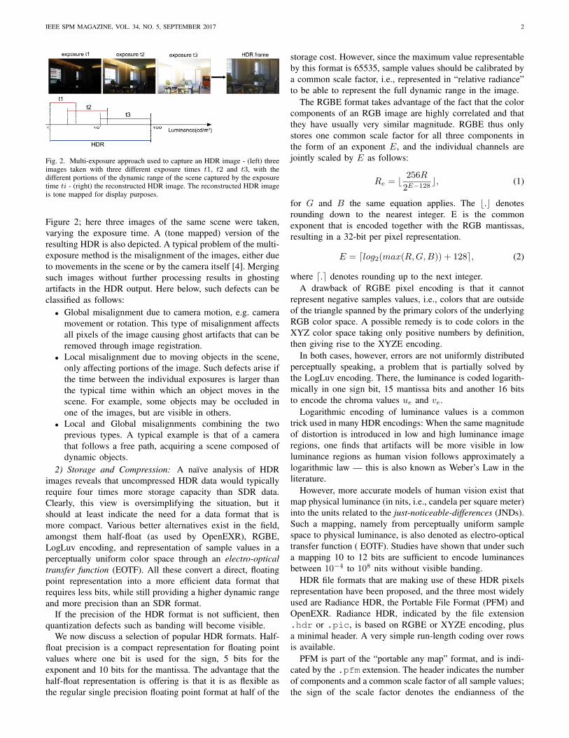
Fig. 4. Global vs Local - Global approach results in lost of details in highcontrast regions. The HDR frame is tone mapped for display purposes.
printing process while keeping the visualization convincing.Tone mappers can be roughly classified into global and localapproaches. The former is applying the same tone curve onthe all image pixels. The latter takes the spatial position andits surrounding into account; by that, local operators can takeadvantage of known effects of the human visual system such aslocal eye adaption to the luminance. While the former is simpleand efficient, it may fail to reproduce details in high contrastimage regions (see Figure 4 (top-left)). Although the latter canreproduce details in such regions better, see Figure 4 (bottom-left), it often comes at the cost of increased complexity andcomputational time; it may also introduce artifacts aroundedges.
Despite this classification, we may also categorize the tonemappers based on their intent. Three main categories of tonemappers can be identified: based on visual system, for scenereproduction and for best subjective quality. The first aimsat integrating into the tone mapper mechanisms that simulatevarious aspects of the human visual system. This includesglare, luminance and chromatic adaptations, night vision, etc.The second category attempts to reproduce the best match incolor gamut and dynamic range available for the display onwhich the image will be visualized. This is achieved throughthe preservation of the original scene’s appearance. The lastcategory produces images with most preferred subjective qual-ity. Typical examples are operators with parameters that canbe adjusted to achieve a specific artistic goal.
Color Correction Dynamic range mismatches between theHDR data and display devices, as previously shown, aretypically handled by tone mappers, focusing on one dimen-sion of the color gamut, along the luminance direction. Thisgenerates two major drawbacks. First, appearance effects areoften ignored, leading to images which may appear poorly ortoo saturated as shown in Figure 5 (left) [8]. Second, sucha tone mapper may not guarantee that all the sample valuesof the tone mapped image are within the available target, asshown in Figure 5 (right). Even though the output luminancemay be reproducible by the display, the chrominance may fallout of the available gamut, resulting in clipping of extremecolors. This clipping may again introduce hue shifts and image
defects. [9].
Fig. 5. Tone mapper drawbacks - (left) changes in appearance due to eithera reduction or an excessive saturation, - (right) pixels may be within thedestination gamut only for the lightness channel L∗; however, their chromachannel may still be out of gamut. Here the HDR input image has been tonemapped for display purposes. Left image courtesy of Francesco Banterle andright image courtesy of Tania Pouli.
To improve the saturation of the tone mapped image, asimple solution is to introduce an adjustable parameter whichallows to control the overall saturation of the tone mappedimage [10]. In the following, let p be a parameter in [0, 1],then
It =
(IoLo
)p
Lt, (3)
Here Io is the input HDR image, It is the final output tonemapped image (both in RGB values), Lo is the luminance ofthe original HDR image and Lt is the luminance of the tonemapped image. The parameter p then needs to be selected forthe best — most pleasing — result. Unfortunately, the simplesolution presented above does not only adjust the saturation, italso implies a luminance shift. Controlling p to get the desiredeffect may be hard. This problem can be overcome by a morecareful choice of the input and output scaling operation [10]:
It =
((IoLo− 1
)p+ 1
)Lt. (4)
While this allows better control of the luminance shift, itmay cause undesirable hue artifacts [8] if applied separatelyto each component of an RGB image. The value of p inthe above equations can be automated based on the slope ofthe tone curve at each luminance level [10]. To reduce hueand lightness shifts, one may work with perceptual uniformcolor space to separate the color appearance parameters suchas saturation from hue and lightness. This will allow tomodify the saturation, of the tone mapped image, to match thesaturation of the input HDR image while hue and lightness ofthe tone mapped image It will remain untouched [8]. Otherapproaches exploit the use of color appearance models,andextend the concept of gamut mapping of the HDR content [9].The former approach guarantees the matching of the colorappearance attributes between the input HDR and the tone

IEEE SPM MAGAZINE, VOL. 34, NO. 5, SEPTEMBER 2017 5
mapped images. The latter ensures that all the tone mappedpixels are within the color gamut of the display, minimizingthe hue and luminance distortion.
Inverse Tone Mapping The latest standardization trendsand technological improvements push the display featurestowards ultra HD, higher dynamic range (HDR), i.e., up to1, 000 and 6, 000 nits, and wide color gamut (ITU-R Rec.2020). Since traditional LCD panels with constant backlightillumination are not able to reproduce the necessary dynamicrange, HDR displays make use of a modulated backlight.In such a display, a front-layer LCD panel includes thecolor filters and provides the necessary level of details foraccurate image reproduction and a lower resolution matrixof independently controlled LEDs modulate its illuminationat a coarser level, providing a much larger dynamic range.Optical layers and reflectors around each LED maximize thebrightness in its corresponding area of the front LCD paneland minimize the light leakage into adjacent cells. Due to thecoarser resolution of the back panel image quality degradationmay appear, which can be reduced through the use of postprocessing filtering of the displayed image.
The widespread availability of SDR content and the recentavailability of displays with larger dynamic range also madeit attractive to process such content for presentations on HDRdisplays. This process can be seen as the opposite problem oftone mapping, and is thus called “inverse tone mapping”. Theability to reconstruct the mapping between the pixel valuesencoded in the SDR image and the scene luminance values,also known as inverse camera response function, is the desir-able goal. While it is an easy task to reconstruct the cameraresponse function from a series of different exposures of thesame SDR content, it is an ill-pose problem to reconstructsuch an inverse when only a single exposure of an unknowncamera is available.
The camera response function models the complete pipelinefrom light acquisition to SDR pixel values, including the (non-linear) sensor response, exposure, camera post-processing (e.g.flare-removal) and tone mapping of raw pixel values to SDRsample values. Recovering the dynamic range for an SDRcontent will consist of two basic steps. First, estimate aninverse camera response function to linearize the SDR contentsignal, then adjust the dynamic range of the SDR pixel to fitit to the dynamic range of the HDR display. However, SDRimages are presenting two major issues when expanding themto larger dynamic range. First, the limited pixels precision, i.e.,quantization to 256 values per channel, causes loss of detailand posterization. These artifacts while barely visible in theSDR domain, can be emphasized during the expansion of thedynamic range. Second, under and over-exposed regions in theSDR image contain very limited information. This may lead,during the dynamic range expansion, to regions that have thesame appearance as in the original SDR image.
To solve the first problem, advanced filtering is neededbefore boosting the dynamic range of the SDR image. Bilateralfiltering is an example: by tuning its parameters properly, high-and low frequencies can be processed separately avoidingsome of the typical artifacts of range-expansion. While lostimage content cannot be recovered in any way, to solve the sec-
ond problem, inpainting may at least generate plausible imagedetails in under- or overexposed image regions, provided theregions are sufficiently small and enough details are availablearound them.
4) HDR Quality Indices: The evaluation of the quality ofan image or video is one of the fundamental steps in under-standing whether the algorithm is capable of achieving a levelof quality acceptable for a specific application. Dependingon whether the original source is available when assessinga somewhat distorted image or video, one distinguishes be-tween “full reference” and “no reference” quality indices. Ifonly partial information on the original is available, they arecalled “reduced reference” indices. In a second dimension, wecan distinguish between “objective” and “subjective” qualityindices. In the former method, a computer algorithm quantifiesthe differences between a reference and a test image or video.Such an algorithm may include a model of the human visualsystem, and then evaluates the visibility of image defects interms of its observer’s model. The latter method, evaluatesquality through studies by human observers. Based on aparticular test methodology, observers are asked to qualifycharacteristics of single or pairs of visual stimuli in form ofimage or video and to provide a score on a scale, or a relativerating between multiple presentations. Certainly, the secondmethod is capable of catching all aspects of human vision andis thus more appropriate to evaluate (or even define) the qualityof an image or a video. It is, however, also very resource andtime consuming and only a limited number of media artifactscan be rated by such a method. Objective quality indices,as computer implementations, are more convenient as theyallow automatic assessment. However, they are less reliablein estimating the overall image quality as their assessment isbased on a limited mathematical model.
While reliable objective full-reference metrics are knownand have been studied multiple times, no-reference qualityprediction by computer algorithms is a much harder problem.Subjectively, both full and no-reference methods are in use,though might answer slightly different questions. Full refer-ence methods measure “fidelity” — how close is the distortedimage to the reference — while no-reference methods rate theoverall “quality” of a presentation.
In the following, we will focus on full-reference objec-tive quality indices. Here one can again distinguish betweendisplay-referred and luminance-independent metrics. The for-mer expect that the values in images or video correspond to theabsolute luminance emitted from a display on which a presen-tation is shown. The latter accept any relative radiance valuesas input. They assume that human vision is approximatelyscale-independent, a property that is equivalent to the “Weber’sLaw”.Generally, the objective metrics designed for SDR suchas PSNR and SSIM are ill-suited for HDR content. Thesemetrics take as input a gamma corrected image and considerthis content in an approximate perceptually uniform space.However, this assumption is valid for CRT displays that areworking typically in low luminance range (0.1 to 80 nits). Thisis not anymore valid for brighter displays. Here distortionsthat are barely visible in CRT displays, will be noticeable.A simple encoding of the physical luminance that makes

IEEE SPM MAGAZINE, VOL. 34, NO. 5, SEPTEMBER 2017 6
objective metrics for SDR content applicable for HDR contentis to transform luminance values into a perceptually uniform(PU) space. Two major objective metrics for evaluating HDRcontent directly have emerged lately [11], [12]. Both are full-reference human visual system based metrics. HDR-VDP-2 is an objective metric capable of detecting differences inachromatic images. For that, it includes a contrast sensitivitymodel inspired by the properties of the human visual systemfor a wide range of luminance values. The metric takes testand reference HDR images as input which are then mappedfirst to a perceptual space and frequency-filtered in severalorientation and frequency specific subbands modeling the firstlayer of the visual cortex. In each subband, a masking modelis applied. The subband wise difference of the cortex-filteredoutput is then used to predict both visibility as the probabilityof defect-detection, and quality, as the perceived magnitude ofdistortion.
The dynamic range independent (DRI) metrics attempt toevaluate image quality independent of the dynamic rangeof the two images to be compared. If the dynamic rangewould be identical, the pixel-wise difference between testand reference images would already provide an indicator ofthe visible artifact to be measured. If the dynamic range isdifferent, though, a per-pixel difference could either be due toan image defect degrading image quality, or due to the changeof the dynamic range. In the latter, the visible differencesin the test image should not be classified as visual artifacts.To distinguish between the two causes, such metrics apply amodel of the HVS based on the detection and classificationof visible changes in the image structure. These structuralchanges are a measure of contrast, and can be categorizedas follows[12]:
• loss of visible contrast, i.e., if a contrast is visible in thereference image but is not anymore visible in the testimage. This happens, for example, if the tone mappercompresses details so much such that they become invis-ible after tone mapping.
• amplification of invisible contrast, i.e., the opposite ofthe above effect. This type of degradation is typical forinverse tone mapping when, due to contrast stretching,contouring artifacts start to appear.
• reversal of visible contrast, i.e., if the contrast in the testimage is the inverse of the contrast in the reference image.Such defects appear, for example, due to clipping aftertone mapping.
The evaluation of HDR video content is also a very impor-tant issue in various applications and standardization activities.Recently, the HDR-VQM metric has been proposed [11] toprovide a feasible objective metric to evaluate quality in HDRvideo content. Video quality is computed based on a spatio-temporal analysis that relates to human eye fixation behaviorduring video viewing.
IV. WHAT WE HAVE LEARNT
Based on this article, readers could have learned what HDRimagery is, including all steps involved in its specific imagingpipeline, and what extra features it is capable to provide to
the end-user. In particular, HDR imagery is conveying to theend-user an extraordinary experience, when compared to thetraditional digital imaging as known today, e.g., 8-10 bits. Tobetter understand improvements introduced by HDR content,which is perceived by the end-user, one can compare it towhat happened about 50 years ago when television movedfrom black/white to color.
V. ACKNOWLEDGMENTS
EPFL author acknowledge the Swiss State Secretariat forEducation, Research and Innovation (SERI), for the EuropeanUnion’s Horizon 2020 research and innovation programme un-der the Marie Sklodowska-Curie grant agreement No 643072- QoE-Net.
REFERENCES
[1] A. Artusi, F. Banterle, T. O. Aydin, D. Panozzo, and O. Sorkine-Hournung, Image Content Retargeting: Maintaining Color, Tone, andSpatial Consistency, September 2016.
[2] A. Artusi, R. Mantiuk, T. Richter, P. Korshunov, P. Hanhart, T. Ebrahimi,and M. Agostinelli, “JPEG XT: A Compression Standard for HDRand WCG Images [Standards in a Nutshell],” IEEE Signal ProcessingMagazine, vol. 33, no. 2, pp. 118–124, 2016.
[3] P. Debevec and J. Malik, “Recovering high dynamic range radiance mapsfrom photographs,” in SIGGRAPH ’97: Proceedings of the 24th annualconference on Computer graphics and interactive techniques. NewYork, NY, USA: ACM Press/Addison-Wesley Publishing Co., 1997, pp.369–378.
[4] S. Pradeep and C. Aguerrebere, “Practical high dynamic range imagingof everyday scenes: Photographing the world as we see it with our owneyes,” IEEE Signal Processing Magazine, vol. 33, no. 5, pp. 36–44,2016.
[5] A. Artusi, R. Mantiuk, R. Thomas, H. Philippe, K. Pavel, A. Massimil-iano, T. Arkady, and E. Touradj, “Overview and evaluation of the JPEGXT HDR image compression standard,” Real Time Image ProcessingJournal, 2015.
[6] R. Thomas, A. Artusi, and E. Touradj, “Jpeg xt: A new family of jpegbackward-compatible standards,” IEEE Multimedia Magazine, 2016.
[7] R. Mantiuk, A. Efremov, K. Myszkowski, and H.-P. Seidel, “Backwardcompatible high dynamic range MPEG video compression,” ACM Trans.Graph., vol. 25, no. 3, pp. 713–723, 2006.
[8] T. Pouli, A. Artusi, F. Banterle, A. O. Akyuz, H.-P. Seidel, andE. Reinhard, “Color correction for tone reproduction,” in Color andImaging Conference. Society for Imaging Science and Technology,November 2013.
[9] E. Sikudova, T. Pouli, A. Artusi, A. Ahmet Oguz, B. Francesco,E. Reinhard, and Z. M. Mazlumoglu, “A gamut mapping frameworkfor color-accurate reproduction of HDR images,” IEEE Transaction ofComputer Graphics and Applications, 2015.
[10] R. Mantiuk, R. Mantiuk, A. Tomaszewska, and W. Heidrich, “Colorcorrection for tone mapping,” Computer Graphics Forum (Proc. ofEUROGRAPHICS 2009), vol. 28, no. 2, pp. 193–202, 2009.
[11] M. Narwaria, R. K. Mantiuk, M. P. Da Silva, and P. Le Callet, “HDR-VDP-2.2: A calibrated method for objective quality prediction of highdynamic range and standard images,” Journal of Electronic Imaging,vol. in print, 2015.
[12] T. O. Aydin, R. Mantiuk, K. Myszkowski, and H.-P. Seidel, “Dynamicrange independent image quality assessment,” ACM Trans. Graph.(Proc. of SIGGRAPH), vol. 27, no. 3, pp. 69:1–69:10, Aug. 2008.[Online]. Available: http://doi.acm.org/10.1145/1360612.1360668
Alessandro Artusi ([email protected]) is a researcher at KIOSResearch and Innovation Center of the University of Cyprus. He is a memberof the ISO/IEC/JCTC1/SC29/ WG1 Committee (also known as JPEG), one ofthe editors of the JPEG XT standard, and recipient of the Emerging StandardsAwards from the British Standard Institute.
IEEE SPM MAGAZINE, VOL. 34, NO. 5, SEPTEMBER 2017 7
Thomas Richter ([email protected]) is a researcher at the TIKComputing Center of the University of Stuttgart. Member of SC29WG1 since2003.
Touradj Ebrahimi ([email protected]) is a professor at Ecole Poly-technique Federale de Lausanne heading its Multimedia Signal Processinggroup. He is also the convenor (chair) of the JPEG Standardization Committee.
Rafał K. Mantiuk ( [email protected]) is a senior lecturer at the ComputerLaboratory, University of Cambridge, United Kingdom. He is the author ofa popular HDR image quality metric, HDR-VDP-2; the coauthor of pfstools,software for high-dynamic range image processing.