Embed Size (px)
Citation preview
IEEE PES/IAS CONFERENCE ON SUSTAINABLE ALTERNATIVE ENERGY, VALENCIA, 2009, 1
Decomposing Objectives and Functions in PowerSystem Operation and Control
Kai Heussen, Student-Member, IEEE and Morten Lind
Abstract—The introduction of many new energy solutionsrequires the adaptation of classical operation paradigms in powersystems. In the standard operation paradigms, a power system isseen as some equivalent of a synchronous generator, a power lineand an uncontrollable load. This paradigm is being questionedby a diverse mix of challenges posed by renewable energysources, demand response technologies and smart grid concepts,affecting all areas of power system operation. Both, new controlmodes and changes in market design are required eventually.A proper redesign should starts with a coherent approach tomodeling. This paper presents a mean-ends perspective to theanalysis of the control structures and operation paradigms inpresent power systems. In a top-down approach, traditionalfrequency- and area-control mechanisms are formalized. It isdemonstrated that future power system operation paradigms withdifferent generation control modes and controllable demand canbe modeled in a coherent way. Finally, the discussion is openedup toward a formalization of service-exchange between marketparticipants.
Index Terms—Smart Grid, Functional Modeling, Power Sys-tem Control, Area Control, Distributed Resources, ControllableDemand
I. INTRODUCTION
Traditionally, the overall objective of power system op-eration is reliable supply of electrical energy to a passiveconsumer. Modern energy systems combine this objective withthe goal of a sustainable and economical allocation of energysources. Many of the concepts and technologies that have beenintroduced in this field imply a paradigm shift: Generation maybe disturbing the system balance if it is sustainable energy,and demand may be active in restoring the balance. The newsituation may be commonly accepted amongst researchersin the field and in the view of todays’ small to mediumscale penetration of renewable energies. However, taken to alarger scale a new understanding of power system operationis required and possible barriers should be faced.
The power system and its future challenges can be viewedfrom different standpoints, relating to different technologybackgrounds and focus areas (e.g. electricity and grid op-eration, generation and balancing of large scale renewables,information technology focusing on means of communication).Virtual power plants, smart grids, microgrids or virtual utilitiesare all synonymous with the need for a shift toward a newoperational paradigm.
All authors are with the Department of Electical Engineering, TechnicalUniveristy of Denmark, 2800 Kgs. Lyngby, Denmark
e-mail: {kh,hhn,mli}@elektro.dtu.dkThe work presented in this paper is a result of the research project Coherent
Energy and Environmental System Analysis (CEESA), partly financed by TheDanish Council for Strategic Research.
Smart grid technologies affect all levels of system operation,and is driven by trends toward further economic deregulation,the advent of more renewable and distributed energy technolo-gies and the additional overall sustainability goals (e.g. [1]).The emergence of these smart grid technologies emphasizethe need for a deeper understanding of how these increasinglycomplex power systems are composed, and how they could bere-composed.
In fact, advanced information technologies are becomingkey for the smart grid [2]–[4], and a tighter integration betweeninformation systems and grid operation will be required. Thedesign of this integration, however, requires knowledge aboutthe decomposition of the control systems and an understandingof the roles of new (distributed) resources [5], [6].
A large number of smart grid concepts are based on someprinciple of aggregation. Two types of aggregation conceptscan be found in most solutions: (1) Aggregation based onthe location of resources in the grid (physical/electrical), and(2) commercial aggregation concepts directed toward a marketintegration. The former are aimed at improving the technicaloperation of the system, and research in this area is of rathertechnical nature. The functions aggregated here are mostlyancillary services, including frequency- and voltage- controlfunctions. Commercial aggregation concepts (2) are strivingfor a profitable participation in energy markets, and research inthis direction focuses on the economical and market-operationprinciples. In this type of aggregation, subsystem functions areunderstood and aggregated as tradeable resources. Aggregatorstypically establish a marketplace or issue price signals directly.
It is in the nature of aggregation to move away from aspecific implementation to a more general understanding of theroles or functions a component has in a system context. Theseroles need to be reconsidered from a system integration pointof view, which requires a shift in perspective: Formulatingthe functions of the system and its subsystems, rather thanthe technical capabilities and structure of the components [7]–[9]. Modeling in terms of functions helps to understand andexpose the complex interactions between information flowsand component capabilities.
The insight that a more fundamental understanding is re-quired leads back to the analysis of overall goals, yet thesegeneral goals do nothing in defining the structure of a powersystem. A goal-decomposition must be based on the physicaland engineering concepts that constitute an electrical energysystem. Different types of models and system understandingare accordingly required at different levels of decomposition.
In this paper we show how a goal-decomposition can bedone by reframing power system operation into a formalmeans-ends perspective. The result is a model of energy flows
IEEE PES/IAS CONFERENCE ON SUSTAINABLE ALTERNATIVE ENERGY, VALENCIA, 2009, 2
a) b)
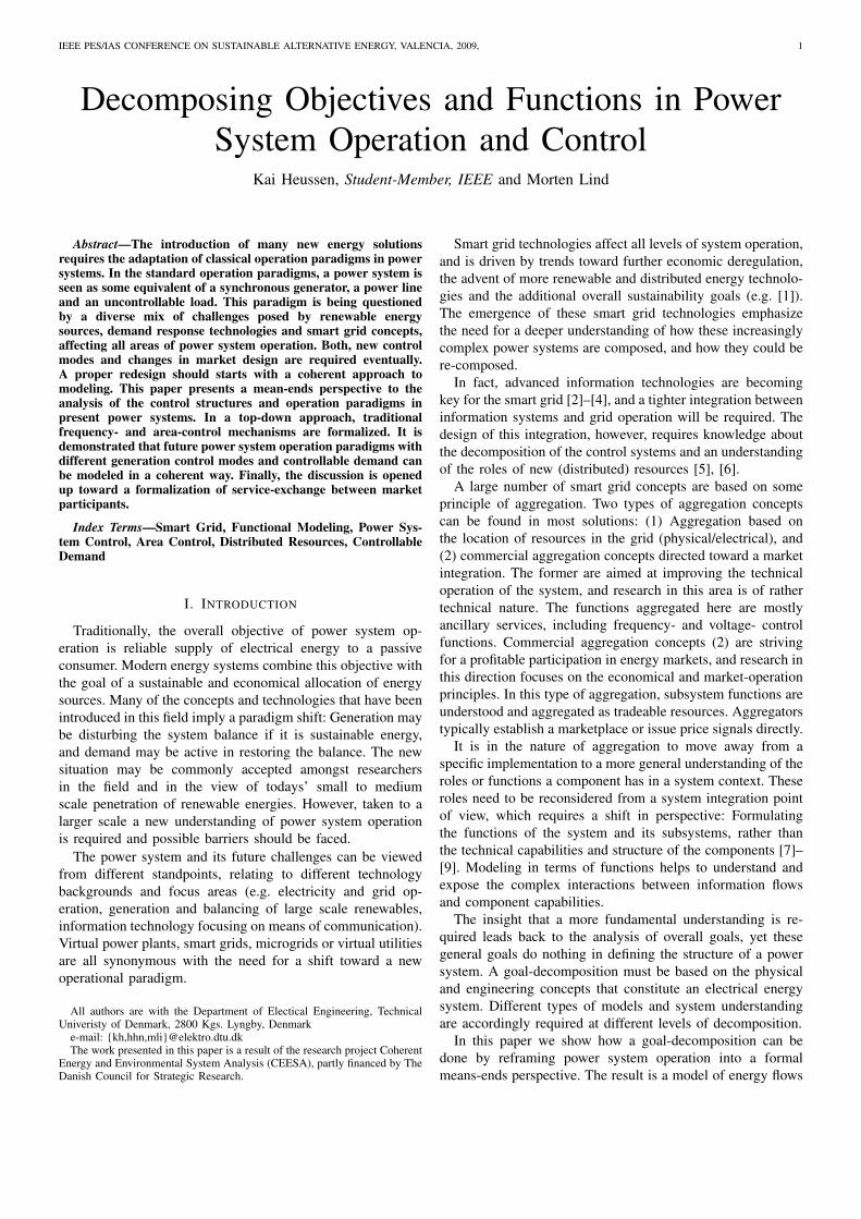
Fig. 1. a) MFM entities and b)MFM relations
and control functions that can reveal the integration of under-lying physical and engineering design concepts into a goal-oriented structure. The subsequent presentation of examplesfor the modeling of typical functions of sustainable generationtechnologies illustrates that a modeling of sustainable energysystems is possible in the same framework.
At first the modeling will follow a textbook description offrequency control, extending on results of an earlier paperby the authors [10]; further operational practices are modeledaccording to the Operation Handbook of the UCTE system1.In a next step, the model is extended to represent the specialroles of uncontrollable generation and controllable demand.The result is a top-down, multi-level decomposition of powersystems in terms of control objectives and means for theirachievement.
In a final discussion, the role of markets in the integrationof control structures constituted by independent entities isanalyzed with a means-ends point of view.
II. MULTILEVEL FLOW MODELING
Multilevel Flow Modeling (MFM) is an approach to mod-eling goals and functions of complex industrial processesinvolving interactions between flows of mass, energy andinformation [11]–[16]. MFM has been developed to supportfunctional modeling [17] of complex dynamic processes andcombines means-end analysis with whole-part decompositionsto describe the functions of the process under study and toenable modeling at different levels of abstraction.
1Using P1: Load Frequency Control and Performance, and P2: Accountingand Scheduling, as well as the appendices A1 and A2. Available at http://www.ucte.org/resources/publications/ophandbook/
In MFM, process functions are represented by elementaryflow functions interconnected to form flow structures with acommon flow object (energy or mass). Connections betweenfunctions within flow structures can be assigned with causalroles, indicating the assignment of an active or passive partic-ipation in the transport of the flow object. Each flow structurerepresents a particular goal-oriented view of the system (Fig-ure 1a)). Objectives can be combined with elementary controlfunctions to form control flow structures. Flow structures areinterconnected in a multilevel representation through means-end relations, and control relations (Figure 1b)).
MFM is founded on fundamental concepts of action [15]and each of the elementary flow and control functions canbe seen as instances of more generic action types. The viewsrepresented by the flow structures, functions, objectives andtheir interrelations comprise together a comprehensive modelof the functional organization of the system represented asa hypergraph. It should be noted that MFM is a formalizedconceptual model of the system which supports qualitativereasoning about control situations [18], [19].
MFM has been used to represent a variety of complex dy-namic processes including fossil and nuclear power generation[20]–[22] and several kinds of chemical processes (e.g. [23]).
Application of MFM includes model based situation assess-ment and decision support for control room operators [24],hazop analysis [25], alarm design [26], alarm filtering [27]and planning of control actions [20], [28]. MFM is supportedby knowledge based tools for model building and reasoning[16].
Application of MFM in power systems is envisioned tofurther intelligent agent solutions in power systems control.MFM models could support situation-awareness of agents, forexample to enable reasoning about appropriate responses infault situations [29]. It has been shown in a previous paperby the authors that the capability of representing control isessential for capturing the functional complexity of powersystems [10]. Here we extend the results from the previouspaper to control areas and expose some first alterations thatenable to represent modern sustainable energy ressources.
III. POWER SYSTEM OBJECTIVES, VALUES AND MEANS
Energy systems are a means to the end of supplying anddistributing energy to all members of society. We value energybeing permanently available and thus the main objective ofpower systems ought to be the reliable supply of electricalenergy; today most would agree, that this objective should bepursued with due respect for future generations and not at allcosts. We say it should be sustainable and economical.
As an entry point for the later analysis it is important toclarify our understanding of values, goals/objectives and thedifferent categories of means.
A goal states the intention associated with a system2. Valuesare valid without a given system context and they generallyqualify goals. The attributes “reliable”, “economical” and“sustainable” further qualify the way in which the means
2In MFM, goals and objectives are distinguished: Goals are more general,rather value-driven, whereas objectives are more formal, rather process-driven.
IEEE PES/IAS CONFERENCE ON SUSTAINABLE ALTERNATIVE ENERGY, VALENCIA, 2009, 3
(power system) should be organized3. These attributes relate tovalues that are associated with our energy supply. These valuesmay be generalized to (1) Security of Supply, (2) ResourceEfficiency and (3) Sustainability [10]. On the one hand, apower system is a technical infrastructure, dealing mostly witha very specific form of electric energy. On the other hand,because it provides fundamental services to society, the systemalso reflects the values its users associate with their energysupply.
Means as analyzed in the context of MFM are functionalmeans – a function is the role of an entity in an action directedat an intentional change of a systems’s state.
Generally, means are actions or things used to achieve anend. Means are therefore naturally fitted for specific types ofpurposes, which means that one could talk about categories ofmeans by purpose:
- electric technology means: grid, generators, active / reac-tive power, control, supervision, system balancing, ...
- information technology means: networks, protocols, soft-ware agents, ...
- control means: measurement, actuation and decision-making equipment.
- economical means: markets, bids, money value, ...The means of electric technology come to define the
structure of the electricity systems. It is typical, that thegeneral objective and the values get into the background inthe process of technology development, sometimes due to alack of appropriate decision making tools. It can be observedthat “reliability” is often evaluated and implemented directlyby the technologists with a focus on the secure operationof the system power system. Economical means are used tocoordinate efficient use of resources. One may add anothercategory of means: Means of sustainability (evaluation), suchas “life-cycle analysis” (LCA).
However, any modeling approach that focuses on one par-ticular type of means tends to give an incomplete view ofthe overall workings (interactions) of a system. An action-based perspective reveals, that in fact all means of technology,economy and control are intertwined on virtually all levels ofdecomposition.
We see functional modelling as a tool that can reflect andexpose the complex entanglement of these means.
IV. MFM MODEL OF STANDARD FREQUENCY CONTROL
In this section we formalize the existing operation andcontrol paradigms of power systems. The control functionspresented here are known and well described in the literature[30]–[32].
This formal understanding may lend itself to a number ofuses, including the types of applications stated in SectionII, such as situation awareness in disturbance situations orautomatic planning of control actions for intelligent agents.
The most abstract view of the multilevel flow model isshown in Figure 2. The symbols used in this diagram are
3Other attributes often stated include: competitiveness, CO2-reduction,wind-integration, etc. These qualifiers are overly specific and may well reflecta lock-in to typical and existing solutions.
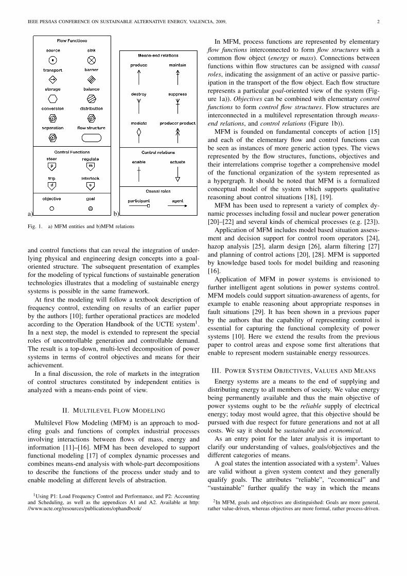
Fig. 2. Abstract view of the electrical energy system (MFM model). Here,“Generation follows demand” is logically represented by the assignment ofcausal roles. The passive causal role of “Generation” is enabled by frequencycontrol.
introduced in Figure 1. The energy system is here describedby an energy flow structure S1, describing a process view,and its association with a goal g1: Satisfy energy demand.Flow structure and goal are connected by a means-end relation:produce, which expresses that this goal is to be achieved bythe system.
S1 comprises three energy flow functions: An energy sourcecalled “Generation”, a transport function called “Delivery”,and an energy sink called “Demand”. These elements representbasic function types: be a source (provide), transport and bea sink (consume).
The flow functions are interconnected by causal relations.A box or arrow at a transport function indicates the causalroles of a connected function. An arrow shows the “agent”role, i.e. the capability of causing a state change in thetransport function; a box means (passive) partication. In Figure2 “Generation” is a passive participant or sender, supplyingenergy to the transport function, whereas Demand is an agentinfluencing the energy flow. These causal roles imply thatgeneration is supposed to be following the load demand. Thiscausal role is enabled by the frequency control functions thatwill be analyzed below. The transport function in S1 representsthe function of power-delivery at any time.
The objective o1 represents the purpose of frequency con-trol. This purpose can be formalized as follows:
o1 : PG!= PD , (1)
where PD is the power consumed by the demand, and PG
is the shaft power of the generators. This equation is thestatement of intention that is PG shall equal PD (not the otherway around). Reading from left to right, this is expressed bythe exclamation mark ( !=).
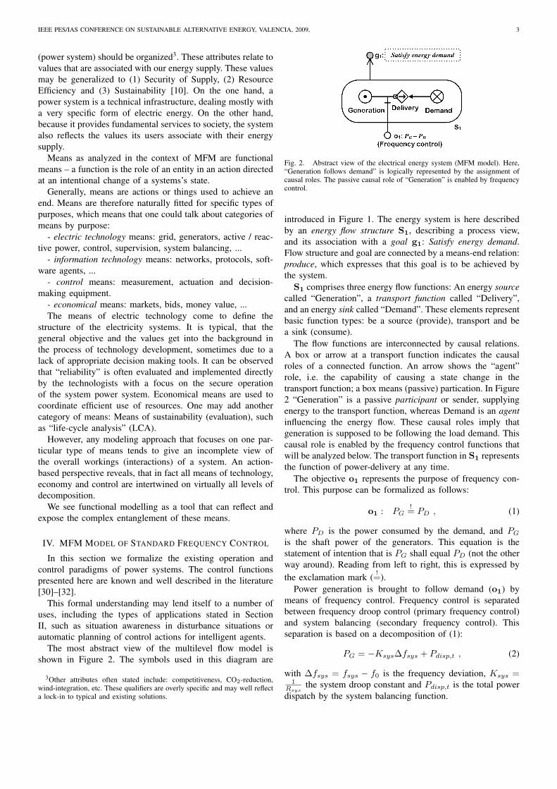
Power generation is brought to follow demand (o1) bymeans of frequency control. Frequency control is separatedbetween frequency droop control (primary frequency control)and system balancing (secondary frequency control). Thisseparation is based on a decomposition of (1):
PG = −Ksys∆fsys + Pdisp,t , (2)
with ∆fsys = fsys − f0 is the frequency deviation, Ksys =1
Rsysthe system droop constant and Pdisp,t is the total power
dispatch by the system balancing function.
IEEE PES/IAS CONFERENCE ON SUSTAINABLE ALTERNATIVE ENERGY, VALENCIA, 2009, 4
Fig. 3. Goal decomposition of frequency control.
The decomposition leads to the objectives o1a and o1b
of droop control and system balancing, respectively. Thisdecomposition of frequency control objectives is shown in Fig-ure 3. Applying control engineering notions, here the systemfrequency control has been split up into separate proportionaland integral controllers.
A. Control Functions: Primary Frequency Control
Droop control or primary frequency control is necessary forthe mitigation of larger short-term deviations in the balancebetween load and demand. Droop control, as the frequency,is shared within the complete synchronous region of a powersystem.
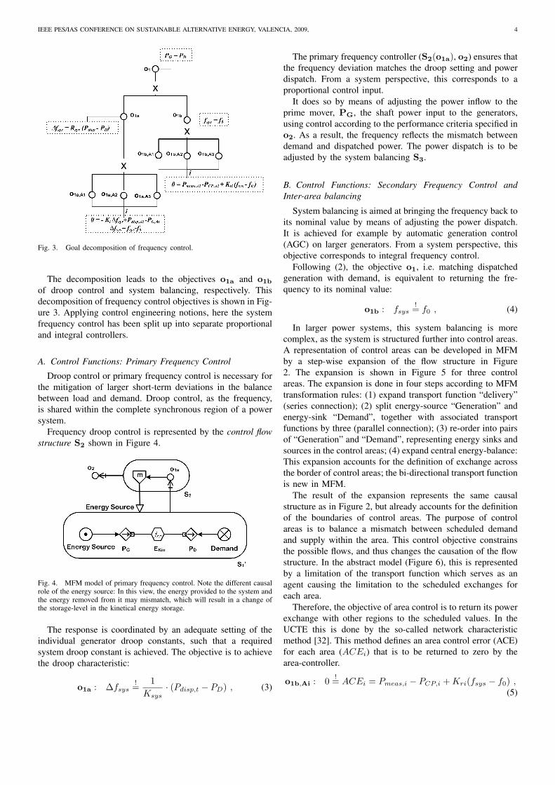
Frequency droop control is represented by the control flowstructure S2 shown in Figure 4.
Fig. 4. MFM model of primary frequency control. Note the different causalrole of the energy source: In this view, the energy provided to the system andthe energy removed from it may mismatch, which will result in a change ofthe storage-level in the kinetical energy storage.
The response is coordinated by an adequate setting of theindividual generator droop constants, such that a requiredsystem droop constant is achieved. The objective is to achievethe droop characteristic:
o1a : ∆fsys!=
1Ksys
· (Pdisp,t − PD) , (3)
The primary frequency controller (S2(o1a), o2) ensures thatthe frequency deviation matches the droop setting and powerdispatch. From a system perspective, this corresponds to aproportional control input.
It does so by means of adjusting the power inflow to theprime mover, PG, the shaft power input to the generators,using control according to the performance criteria specified ino2. As a result, the frequency reflects the mismatch betweendemand and dispatched power. The power dispatch is to beadjusted by the system balancing S3.
B. Control Functions: Secondary Frequency Control andInter-area balancing
System balancing is aimed at bringing the frequency back toits nominal value by means of adjusting the power dispatch.It is achieved for example by automatic generation control(AGC) on larger generators. From a system perspective, thisobjective corresponds to integral frequency control.
Following (2), the objective o1, i.e. matching dispatchedgeneration with demand, is equivalent to returning the fre-quency to its nominal value:
o1b : fsys!= f0 , (4)
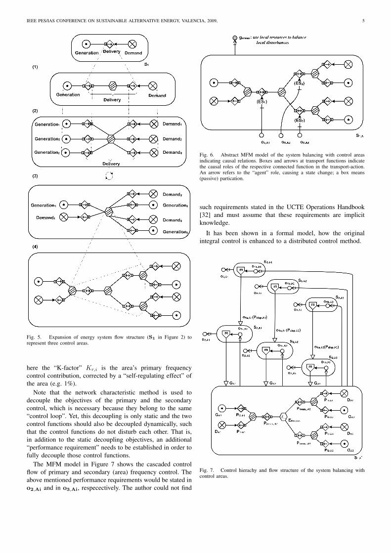
In larger power systems, this system balancing is morecomplex, as the system is structured further into control areas.A representation of control areas can be developed in MFMby a step-wise expansion of the flow structure in Figure2. The expansion is shown in Figure 5 for three controlareas. The expansion is done in four steps according to MFMtransformation rules: (1) expand transport function “delivery”(series connection); (2) split energy-source “Generation” andenergy-sink “Demand”, together with associated transportfunctions by three (parallel connection); (3) re-order into pairsof “Generation” and “Demand”, representing energy sinks andsources in the control areas; (4) expand central energy-balance:This expansion accounts for the definition of exchange acrossthe border of control areas; the bi-directional transport functionis new in MFM.
The result of the expansion represents the same causalstructure as in Figure 2, but already accounts for the definitionof the boundaries of control areas. The purpose of controlareas is to balance a mismatch between scheduled demandand supply within the area. This control objective constrainsthe possible flows, and thus changes the causation of the flowstructure. In the abstract model (Figure 6), this is representedby a limitation of the transport function which serves as anagent causing the limitation to the scheduled exchanges foreach area.
Therefore, the objective of area control is to return its powerexchange with other regions to the scheduled values. In theUCTE this is done by the so-called network characteristicmethod [32]. This method defines an area control error (ACE)for each area (ACEi) that is to be returned to zero by thearea-controller.
o1b,Ai : 0 != ACEi = Pmeas,i − PCP,i + Kri(fsys − f0) ,(5)
IEEE PES/IAS CONFERENCE ON SUSTAINABLE ALTERNATIVE ENERGY, VALENCIA, 2009, 5
Fig. 5. Expansion of energy system flow structure (S1 in Figure 2) torepresent three control areas.
here the “K-factor” Kr,i is the area’s primary frequencycontrol contribution, corrected by a “self-regulating effect” ofthe area (e.g. 1%).
Note that the network characteristic method is used todecouple the objectives of the primary and the secondarycontrol, which is necessary because they belong to the same“control loop”. Yet, this decoupling is only static and the twocontrol functions should also be decoupled dynamically, suchthat the control functions do not disturb each other. That is,in addition to the static decoupling objectives, an additional“performance requirement” needs to be established in order tofully decouple those control functions.
The MFM model in Figure 7 shows the cascaded controlflow of primary and secondary (area) frequency control. Theabove mentioned performance requirements would be stated ino2,Ai and in o3,Ai, respecectively. The author could not find
Fig. 6. Abstract MFM model of the system balancing with control areasindicating causal relations. Boxes and arrows at transport functions indicatethe causal roles of the respective connected function in the transport-action.An arrow refers to the “agent” role, causing a state change; a box means(passive) partication.
such requirements stated in the UCTE Operations Handbook[32] and must assume that these requirements are implicitknowledge.
It has been shown in a formal model, how the originalintegral control is enhanced to a distributed control method.
Fig. 7. Control hierachy and flow structure of the system balancing withcontrol areas.
IEEE PES/IAS CONFERENCE ON SUSTAINABLE ALTERNATIVE ENERGY, VALENCIA, 2009, 6
V. NEW ROLES IN PRESENT AND FUTURE SUSTAINABLEENERGY SYSTEMS
The analysis above gives a compact illustration of thepresent control architecture of power systems. In the followingwe will demonstrate how MFM also can help defining thefunctions and aggregations of new and distributed energyresources.
A. Uncontrollable Generation and Controllable Demand
The models developed above are based on the backgroundassumption that generation at large is controllable (and con-trolled) and that demand is uncontrolled (and uncontrollable);i.e. system imbalances in normal operation are caused by de-mand. This corresponds to the textbook perspective on powersystem control. Nevertheless, the performamnce criterion forfrequency control is given by a design-disturbance, whichtypically determined by the N-1 criterium. So for disturbedoperation, in fact the performance requirements are also guidedby the size of the generators in operation.
Most types of renewable electricity generation do not fitthis classic picture, as their energy-output is not controlled4.One of the central measures for the integration of renewableenergy is the introduction of controllable demand. Just ascontrollable generation this measure increases the adjustablerange of power flows.
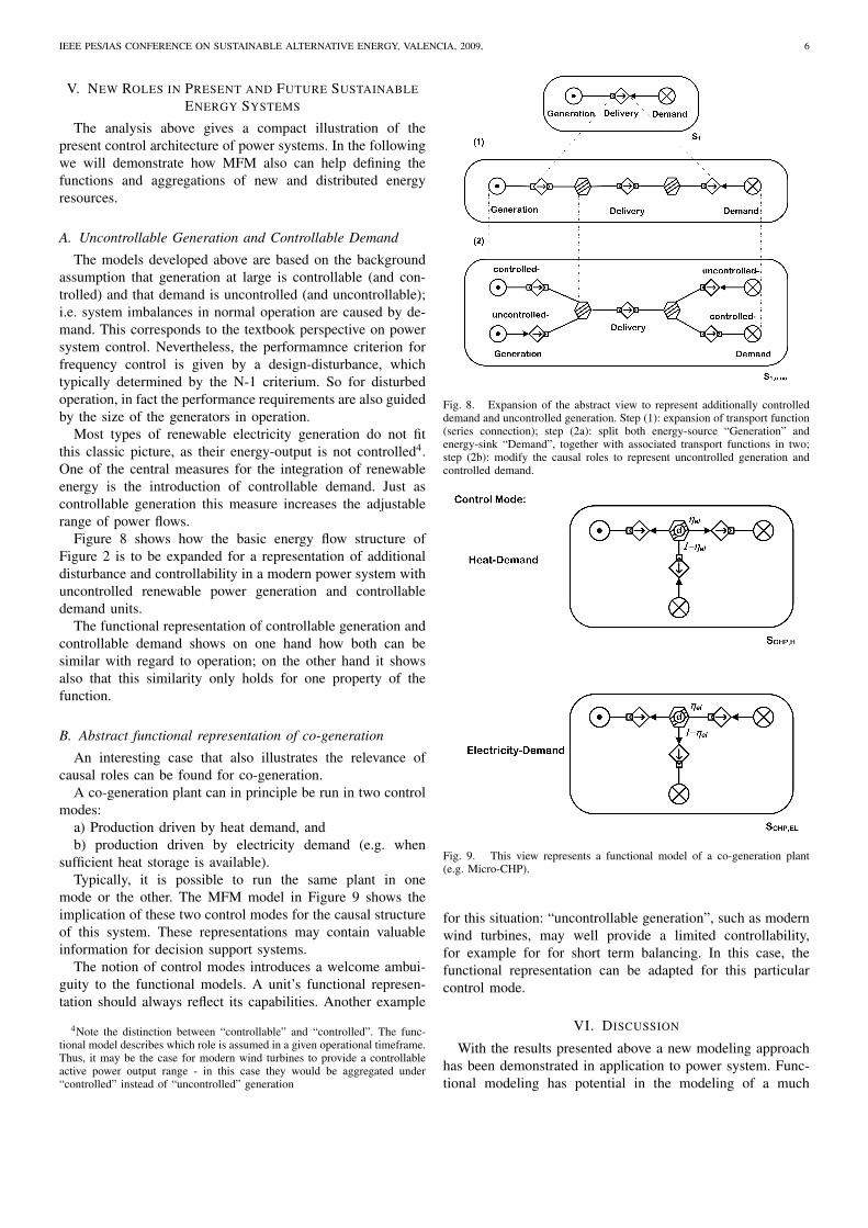
Figure 8 shows how the basic energy flow structure ofFigure 2 is to be expanded for a representation of additionaldisturbance and controllability in a modern power system withuncontrolled renewable power generation and controllabledemand units.
The functional representation of controllable generation andcontrollable demand shows on one hand how both can besimilar with regard to operation; on the other hand it showsalso that this similarity only holds for one property of thefunction.
B. Abstract functional representation of co-generation
An interesting case that also illustrates the relevance ofcausal roles can be found for co-generation.
A co-generation plant can in principle be run in two controlmodes:
a) Production driven by heat demand, andb) production driven by electricity demand (e.g. when
sufficient heat storage is available).Typically, it is possible to run the same plant in one
mode or the other. The MFM model in Figure 9 shows theimplication of these two control modes for the causal structureof this system. These representations may contain valuableinformation for decision support systems.
The notion of control modes introduces a welcome ambui-guity to the functional models. A unit’s functional represen-tation should always reflect its capabilities. Another example
4Note the distinction between “controllable” and “controlled”. The func-tional model describes which role is assumed in a given operational timeframe.Thus, it may be the case for modern wind turbines to provide a controllableactive power output range - in this case they would be aggregated under“controlled” instead of “uncontrolled” generation
Fig. 8. Expansion of the abstract view to represent additionally controlleddemand and uncontrolled generation. Step (1): expansion of transport function(series connection); step (2a): split both energy-source “Generation” andenergy-sink “Demand”, together with associated transport functions in two;step (2b): modify the causal roles to represent uncontrolled generation andcontrolled demand.
Fig. 9. This view represents a functional model of a co-generation plant(e.g. Micro-CHP).
for this situation: “uncontrollable generation”, such as modernwind turbines, may well provide a limited controllability,for example for for short term balancing. In this case, thefunctional representation can be adapted for this particularcontrol mode.
VI. DISCUSSION
With the results presented above a new modeling approachhas been demonstrated in application to power system. Func-tional modeling has potential in the modeling of a much

IEEE PES/IAS CONFERENCE ON SUSTAINABLE ALTERNATIVE ENERGY, VALENCIA, 2009, 7
wider range of promising application fields. In the followingwe discuss the possibility of applying functional modelingsupåported by MFM in two specific areas of difficulty:
a) economic deregulation: representation of controllable anduncontrollable generation in power markets
b) decentralized generation and “aggregation” of controlfunctions
A. Decomposition of Control Functions into Market Entitiesand Exchanged Services
In a market place people meet to exchange goods for money.One can say that a market place is established where at leastone seller offers a good of his own, one or more buyers areinterested in (value) that good and all share a common meansof valuation (money). A deal is made when ownership ofmoney and the good are mutually exchanged between the twomarket entities, typically under the condition that the good-valuation of the buyer meets or exceeds the good-valuation ofthe seller. We talk about “buyer” and “seller” because of therole each individual assumes in the market place. In fact, rolesare defined through the market exchange process, not throughthe individuals taking part in this process.
Yet, the requirement that a good can be exchanged maydepend on more than just the notions of ownership andmoney. Often a number of mutual requirements need to befulfilled before a deal can be made. For example a marketplace traditionally provides support functions to ensure safetyand simplicity of deals. Further properties of both seller andbuyer may be required to enable the exchange of a specificcommodity.
This corresponds to the difficulty in defining service agree-ments: If the good exchanged is not naturally self defined(a piece of something, or subject to a common standard),then buyer and seller need to agree on a definition of theservice being provided. “Energy” would be a relatively simplecommodity, but it requires a specification of the energy carrier.If the carrier is coal, the good is nearly self-defined (a pieceof something). If it is electricity though, the specifics of thesystem function (e.g. the lack of storage) require a strongdefinition of requirements: the power system as the “exchangesystem” requires a cooperative approach to reliability in orderto establish the system function that is necessary for the energyexchange.
In MFM, entities are related to the realization of a function.That is, a flow structure captures the functional compositionof a system, not its realization; a flow structure or a singlefunction may be associated with a physical entity or a virtualaggregation of many. On the other hand, any entity can haveone or several functional self-representations. That is a self-representation of its functions would enable a self-interestedentity to identify requirements when providing and acceptingexternal functions (services).
To illustrate the idea using MFM, Figure 10 shows asimple MFM model of energy exchange between “producer”,“consumer” over an “energy system”. The three basic energyflow structures (source-transport-sink) are interconnected by a“Janus-relation”.
Fig. 10. Sketch of the correspondence between MFM flow structures andmarket entities. The “Janus-relation” (-J-) establishes a connection betweenthe Producer’s sink and the Generation function, as well as between theConsumer’s source and the Demand function.
The “Janus-relation” (-J-) establishes a connection betweencomplementary functions in different flow structures. The twofunctions connected by a Janus-relation represent the samefunctional-entity from different perspectives. For example,an energy-sink is an energy source for another perspective.The two functions share all factual properties, but functionalrequirements, would be tied to the respective flow structure.Thus the physical realization of the energy-sink of this pro-ducer would be identical with the the physical realization ofthe energy-source of the energy system and the consumer’senergy source is identical with the sink of the energy system.The formulation of requirements instead would be with respectto the respective flow structure.
The parallel between the functional (energy) connection ofproducer, consumer and energy system on one hand, and thetheir roles with respect to the market operation on the other, isillustrated in Figure 10. As outlined above, there is a potentialin formulating such economical relations in the same action-theoretical framework as the technical functions treated in theremainder of this paper. The roles of the given entities in thecommodity-exchange-process are indicated.
B. “Functional Aggregation”
As shown in Section IV-B and in Figures 5 and 8, MFMprovides formal rules that guide the expansion and collapse offlow structures. An expansion of a flow function correspondsto a more detailed view of the functional structure of a system,which led to a neww control opportunity in case of the sec-ondary frequency control. From a bottom-up perspective, anarea’s energy source aggregates all generators in the respectivearea. Detailing and aggregation follows along with new controlstructures.
Aggregation is natural in the representation of functions andit lends itself immediately to formalize aggregation concepts.MFM has been developed as a combination of means-endsand whole-part abstraction levels. Current work on MFMformalizes these different representation and abstraction levelsinto a flexible data structure.
Information models that should integrate information aboutdiverse units require a more abstract formalization of the prop-erties of their subsystems. MFM provides a natural frameworkto carry and organize such information.
IEEE PES/IAS CONFERENCE ON SUSTAINABLE ALTERNATIVE ENERGY, VALENCIA, 2009, 8
VII. CONCLUSION
The results in this paper show a further development ofMFM toward a promising modeling tool in the application topower systems in the future. Work lying ahead includes a mod-eling of current modern control concepts such as Microgridsand Virtual Power Plants.
REFERENCES
[1] M. D. Ilic, “From hierarchical to open access electric power systems.”Proceedings of the IEEE, Special Issue on "Modeling, Identification,and Control of Large-Scale Dynamical Systems", vol. 95, no. 5, pp.1060–1084, May 2007.
[2] S. D. J. McArthur, E. M. Davidson, V. M. Catterson, A. L. Dimeas,N. D. Hatziargyriou, F. Ponci, and T. Funabashi, “Multi-agent systemsfor power engineering applications – part I: Concepts, approaches, andtechnical challenges,” Power Systems, IEEE Trans. on, vol. 22, no. 4,pp. 1743–1752, November 2007.
[3] H. Akkermans, J. Schreinemakers, and K. Kok, “Microeconomic dis-tributed control: Theory and application of multi-agent electronic mar-kets,” CRIS, Tech. Rep., 2004.
[4] D. Pudjianto, C. Ramsay, and G. Strbac, “Virtual power plant and systemintegration of distributed energy resources,” IET Renew. Power Gener.,vol. 1, no. 1, pp. 10–16, 2007.
[5] M. Braun, “Technological control capabilities of DER to provide futureancillary services,” Distr. Energy Resources, Int. Journ. of, vol. 3, pp.191–206, 2007.
[6] M. Braun and P. Strauss, “A review on aggregation approaches ofcontrollable distributed energy units in electrical power systems,” Distr.Energy Resources, Int. Journ. of, vol. 4, no. 4, pp. 297–319, 2008.
[7] M. Lind, T. Ackermann, P. Bach, H. W. Bindner, Y. Chen, R. Garcia-Valle, M. Gordon, K. Heussen, P. Nyeng, A. Saleem, P. E. Sørensen,M. Togeby, I. Vlachogiannis, S. You, and Z. Xu, “Ecogrid.dk phase IWP2 report - system architecture,” Energinet.dk, Tech. Rep., 2008.
[8] I. Kamphuis, J. Kok, C. Warmer, and M. Hommelberg, “Architectures fornovel energy infrastructures: Multi-agent based coordination patterns,”in IEEE-NGI, Rotterdam, The Netherlands. ECN, 10-12 November2008, presented, paper available at http://www.ecn.nl/publications/.
[9] O. Gehrke, “Infrastructures for power system integration and controlof small distributed energy resources,” Ph.D. dissertation, TechnicalUniversity of Denmark, 2009, forthcoming.
[10] K. Heussen, A. Saleem, and M. Lind, “Control architecture of powersystems: Modeling of purpose and function,” in Proceedings of the IEEEPES General Meeting 2009, 2009.
[11] M. Lind, “The use of flow models for design of plant operatingprocedures,” in Proc. IWG/NPPCI Specialist meeting on procedures andsystems for assisting an operator in normal and anomalous nuclearpower plant operation situations, Garching, Federal Republic of Ger-many, December 1979.
[12] ——, “The use of flow models for automated plant diagnosis,” in HumanDetection and Diagnosis of System Failures, J. Rasmussen and W. B.Rouse, Eds. Plenum Press, New York, 1981.
[13] ——, “Modeling goals and functions of complex industrial plant,”Applied Artificial Intelligence, vol. 8, no. 2, pp. 259–283, 1994.
[14] ——, “Plant modeling for human supervisory control,” Transactions ofthe Institute of Measurement and Control, vol. 21, no. 4-5, pp. 171–180,1999.
[15] ——, “Modeling goals and functions of control and safety systems inMFM,” in Proceedings International Workshop on Functional Modelingof EngineeringSystems, Kyoto, Japan, January 25 2005, pp. 1–7.
[16] ——, “Perspectives on multilevel flow modeling,” in Proc. 4.th Interna-tional Symposium on Cognitive System Engineering Approach to PowerPlant Control (CSEPC2008), Harbin, Heilongjiang China, September8-10 2008.
[17] ——, “The what, why and how of functional modelling,” in Proceedingsof International Symposium on Symbiotic Nuclear Power Systems for the21’st Century (ISSNP), Tsuruga, Japan, July 9-11 2007, pp. 174–179.
[18] ——, “Status and challenges of intelligent plant control,” Annual Reviewof Control, vol. 20, pp. 23–41, 1996.
[19] A. Saleem, T. Us, and M. Lind, “Means-end based functional modelingfor intelligent control: Modeling and experiments with an industrialheat pump,” in Proc. IASTED conference on Intelligent Control Systems(ICS2007), Cambridge, Massachussets, USA, Nivember 21-23 2007.
[20] M. N. Larsen, “Deriving action sequences for start-up using multilevelflow models,” Ph.D. dissertation, Department of Automation, TechnicalUniversity of Denmark, 1993.
[21] J. Ouyang, M. Yang, H. Yoshikawa, Y. Zhou, and J. Liu, “AlarmAnalysis and Supervisory Control Plan of PWR Plant,” in Proceedingsof CSEPC 2004, Cognitive Systems Engineering in Process Control,Sendai, Japan, Nocember 4-5 2004, pp. 61–68.
[22] J. Liu, H. Yoshikawa, and Y. Zhou, “Application of multilevel flowmodeling to describe complex processes in a nuclear fuel cycle,” inProceedings CSEPC 2004 Cognitive Systems Engineering in ProcessControl, Sendai, Japan, November 4-5 2004, pp. 114–120.
[23] A. Gofuku and Y. Tanaka, “Application of Derivation Technique ofPossible Counter Actions to an Oil Refinery Plant,” in Proc. 4’thIJCAI Workshop on Engineering Problems for Qualitative Reasoning,Stockholm, 1999, pp. 77–83.
[24] J. Petersen, “Situation assessment of complex dynamic systems usingMFM,” in Proceedings of 8th. IFAC/IFIP/IFPRS/IEA Symposium onAnalysis, Design and Evaluation of Human-Machine Systems, Kassel,Germany, September 18-20 2001, pp. 645–650.
[25] N. L. Rossing, M.Lind, N. Jensen, and S. B. Jørgensen, “A goal basedmethodology for hazop analysis,” in Proc. 4.th International Symposiumon Cognitive System Engineering Approach to Power Plant Control(CSEPC2008), Harbin, Heilongjiang, China, September 8-10 2008.
[26] T. Us, N. Jensen, M. Lind, and S. B. Jørgensen, “Fundamental principlesof alarm design,” in Proc. 4.th International Symposium on CognitiveSystem Engineering Approach to Power Plant Control (CSEPC2008),Harbin, Heilongjiang China, September 8-10 2008.
[27] J. E. Larsson, “Diagnosis based on explicit means-end models.” ArtificialIntelligence, vol. 80(1), pp. 29–93, 1996.
[28] A. Gofuku and Y. Tanaka, “Development of an Operator AdvisorySystem: Finding Possible Counter Actions in Anomalous Situations,” inProc. 5’th International Workshop on Functional Modeling of ComplexTechnical Systems, Paris, France, July 1-3 1997, pp. 87–97.
[29] A. Saleem, K. Heussen, and M. Lind, “Agent services for situationaware control of electric power systems with distributed generation,”in Proceedings of the IEEE PES General Meeting 2009, 2009.
[30] P. Kundur, Power System Stability and Control, EPRI, Ed. McGraw-Hill, Inc., 1994.
[31] A. J. Wood and B. F. Wollenberg, Power generation, operation, andcontrol. John Wiley & Sons, 1996.
[32] UCTE Operation Handbook: P1 - Load Frequency Control and Per-formance, 2nd ed., "Union for the Co-ordination of Transmission ofElectricity" (UCTE), 2004, available at http://www.ucte.org/resources/publications/ophandbook/.
Kai Heussen (M’07) is currently a Ph.D. student inAutomation and Electric Energy Systems at the De-partment of Electrical Engineering at the TechnicalUniversity of Denmark. He studied control engineer-ing in Stuttgart and Toronto and received his degreeof Engineering Cybernetics from the University ofStuttgart in 2007. His research interests includecontrol theory, distributed control architecture andthe design of integrated energy sytems with veryhigh shares of renewable energy.
Morten Lind is Professor of Automation at De-partment of Electrical Engineering at Technical Uni-versity of Denmark and is associated Centre forElectric Technology. His research interests includeautomation design, supervisory control of complexindustrial systems and infrastructures, and appli-cation of agent technology and knowledge basedsystem in automation.