Embed Size (px)
Citation preview

This article has been accepted for inclusion in a future issue of this journal. Content is final as presented, with the exception of pagination.
IEEE JOURNAL OF OCEANIC ENGINEERING 1
Mitigating Power Fluctuations in Electric ShipPropulsion With Hybrid Energy Storage
System: Design and AnalysisJun Hou, Student Member, IEEE, Jing Sun, Fellow, IEEE, and Heath F. Hofmann, Senior Member, IEEE
Abstract—Shipboard electric propulsion systems experiencelarge power and torque fluctuations on their drive shaft due topropeller rotational motion and waves. This paper explores newsolutions to address these fluctuations by integrating a hybrid en-ergy storage system (HESS) and exploring energy management(EM) strategies. The HESS combines battery packs with ultra-capacitor banks. Two strategies for real-time EM of HESS areconsidered: one splits the power demand such that high- and low-frequency power fluctuations are compensated by ultracapacitorsand batteries, respectively; another considers the HESS as a singleentity and designs an EM strategy to coordinate the operations ofthe ultracapacitors and batteries. For both strategies, model pre-dictive control is used to address power tracking and energy sav-ing under various operating constraints. To quantitatively analyzethe performance of HESS and its associated controls, a propellerand ship dynamic model, which captures the underlying physicalbehavior, is established to support the control development andsystem optimization. Power fluctuation mitigation and HESS lossminimization, the main objectives, are evaluated in different seaconditions. Simulation results show that the coordination withinHESS provides substantial benefits in terms of reducing fluctua-tions and losses.
Index Terms—Electric ship propulsion, hybrid energy storage,load fluctuation mitigation, model predictive control (MPC),multiobjective optimization.
I. INTRODUCTION
Ship electrification has been a technological trend in com-mercial and military ship development in response to recentenergy efficiency and environmental protection initiatives [1],[2]. Electric propulsion has been playing a central role in thisdesign paradigm shift. The introduction of electric propulsionhas brought about new opportunities for taking a fresh lookat old problems and developing new solutions. Thrust andtorque losses and fluctuations have been identified as inherentelements in the ship propulsion system [3]–[7] due to the hydro-dynamic interactions and wave excitations. Three different load
Manuscript received January 21, 2016; revised August 28, 2016 and Decem-ber 16, 2016; accepted February 21, 2017. This work was supported by theU.S. Office of Naval Research under Grant 00014-11-1-0831 and in part by theU.S. Navy through the Naval Engineering Education Center.
Associate Editor: K. Von Ellenrieder.The authors are with the Department of Naval Architecture and Marine
Engineering and the Department of Electrical Engineering and ComputerScience, University of Michigan, Ann Arbor, MI 48109 USA (e-mail: [email protected]; [email protected]; [email protected]).
Digital Object Identifier 10.1109/JOE.2017.2674878
Fig. 1. Schematic diagram of electric drive system with hybrid energystorage [13].
power fluctuations are studied in this paper: fluctuations from theimpact of the first-order wave at the encounter wave frequency;fluctuations from the in-and-out-of-water effect; and fluctua-tions at the propeller-blade frequency (i.e., number of bladestimes shaft speed in r/s). These fluctuations significantly affectthe performance and life cycle of both mechanical and electri-cal systems involved, as has been analyzed in several publica-tions [8]–[11]. For mechanical systems, excessive fluctuationsin torque and power will increase mechanical stress and causewear and tear. The importance of the mechanical effect causedby the propeller-blade frequency fluctuation has been discussedin [6], [7], [10], and [11]. At the same time, for electrical sys-tems, power fluctuations, especially when the propeller is inand out of water, will cause unpredictable power consumption,reduce electrical efficiency, and even affect power quality onthe shipboard power network [3], [4], [6], [7], [9]–[11], [20].To address this issue, several studies have been discussed in theliterature, such as using thrust control for power smoothing [6],[7]. The tradeoffs between speed control, torque control, andpower control of the motor have been studied in [6].
In this paper, a hybrid energy storage system (HESS) solu-tion has been proposed for mitigating the power fluctuationsof ship electric drivetrains. The concept of the proposed sys-tem is shown in Fig. 1 [12], [13]. The energy storage systemserves as a buffer to absorb energy when the motor is under-loaded and supply energy when overloaded, thereby isolatingthe power network from the propulsion load fluctuations andimproving the overall system efficiency. An HESS will provide
0364-9059 © 2017 IEEE. Personal use is permitted, but republication/redistribution requires IEEE permission.See http://www.ieee.org/publications standards/publications/rights/index.html for more information.

This article has been accepted for inclusion in a future issue of this journal. Content is final as presented, with the exception of pagination.
2 IEEE JOURNAL OF OCEANIC ENGINEERING
Fig. 2. Model structure of the proposed system.
significant performance advantages over a single type of energystorage system, as different energy storage mechanisms providecomplementary features for optimal results.
The integration and operation of the electric propulsion sys-tem with HESS relies on effective energy management strate-gies, as well as properly configured hardware, to achieve thedesired benefits of increased system efficiency, improved relia-bility, and reduced wear and tear. In this paper, we investigateenergy management strategies for an electric propulsion systemwith an HESS to mitigate load power fluctuation effects onshipboard electric propulsion systems. More specifically, weconsider an HESS made of batteries and ultracapacitors (UCs),and explore two control strategies with different levels ofcoordination among the elements within HESS. One decom-poses the power command that is needed to counteract thefluctuations according to their frequency range, then controlsthe battery packs and UC banks independently. This will bereferred to as control with prefiltering (PF) in this paper, asthe charging/discharging of the two components in HESS areoptimized separately after the filtering so that the UCs handlethe high-frequency fluctuations while the batteries deal with thelow-frequency fluctuations. The filter-based strategy has beenexplored and suggested to be one of the most effective energymanagement strategies in hybrid electric vehicle applications[15]–[17]. The other approach, referred to as coordinated con-trol (CC), treats the batteries and UCs as a single entity, andcoordinates their charging/discharging to counteract the totalload fluctuations through an optimization algorithm. The goalof this study is to quantify the performance difference and un-derstand the critical roles of a control strategy in an HESSimplementation. It should be noted that, while the PF leads toa relatively simple low-dimensional optimization problem, theCC is expected to offer improved performance. To evaluate theproposed strategies, two cases are studied. Case I is a worst casescenario study, where the propeller rotational speed is assumedto be constant and the large high-frequency fluctuations occur
on the power network. In Case II, these high-frequency fluctua-tions are filtered by the propeller inertia and a PI controller. Thispaper aims at providing insights that would allow designers tomanage the tradeoff between performance and control complex-ity. To characterize the performance of HESS, the performanceof a single type of energy storage will be included in this studyas a benchmark.
The study presented in this paper is model based. We presenta propeller and ship dynamic model and an HESS model thatcapture the underlying physical dynamic behavior of the com-ponents, particularly the power and thrust fluctuations in thepropulsion load at different sea states. Model predictive control(MPC) algorithms for CC and PF strategies are developed to en-able the application of HESS in ship electric propulsion systemsto achieve the intended design objectives, subject to operatingconstraints. Comparisons between a single type of energy stor-age and HESS with CC and PF strategies are performed. Finally,a sensitivity analysis of the predictive horizon shows the effec-tiveness of the CC strategy in reducing power tracking error andthe promise for real-time applications.
The results presented in this paper are built on [12], whichwas presented at the 2014 American Control Conference. Thispaper significantly expands the preliminary results in [12] by:
1) developing a new MPC strategy for CC to allow the UC tooperate near its most efficient setpoint without violatingconstraints;
2) providing a detailed tradeoff analysis of the HESS withCC and PF strategies in different sea conditions and vali-dating the advantages of the CC strategy with quantitativeresults;
3) presenting a sensitivity analysis of the control designparameters;
4) evaluating the effectiveness of the proposed strategy witha new case study, where the load fluctuations are fil-tered by the propeller inertia and a PI motor speedcontroller.

This article has been accepted for inclusion in a future issue of this journal. Content is final as presented, with the exception of pagination.
HOU et al.: MITIGATING POWER FLUCTUATIONS IN ELECTRIC SHIP PROPULSION WITH HYBRID ENERGY STORAGE SYSTEM 3
Fig. 3. Propeller and ship dynamics model structure.
This paper is organized as follows. Section II presents themodeling of the key components to capture the underlyingdynamics. In Section III, the HESS sizing, based on the fre-quency components of the load fluctuation, is determined forthe case study presented in this paper. Section IV describes theHESS energy management problem formulation and controlstrategies. In Section V, detailed performance evaluations ofeach strategy and a comparison of the strategies are presented.Section VI concludes the paper.
II. DYNAMIC MODEL OF AN ELECTRIC SHIP PROPULSION
SYSTEM WITH HYBRID ENERGY STORAGE
The schematic of the electric propulsion system underinvestigation is shown in Fig. 2. The system consists of a primemover and a generator (PM/G) for power generation, an electricmotor for propulsion, the ship and its propeller, and an HESSpackage. Power converters (i.e., dc/dc and ac/dc converters) areused to connect electrical components. The modeling of eachcomponent is described in this section, and the resulting control-oriented models are presented.
A. Propeller and Ship Dynamic Model
The focus of the propeller and ship model is to capture thedynamic behavior of the propeller and ship motion, including thepower and torque fluctuations induced on the motor drive shaft.The characteristics of the propeller, subject to the wake fieldand in-and-out-of-water effects, are investigated and simulationresults are presented. As shown in Fig. 3, the ship dynamics,propeller characteristics, and motor dynamics are mechanicallycoupled; they influence each other through mechanical connec-tions and internal feedback [13].
1) Propeller Characteristics: The propeller responses, interms of thrust T and torque Q, are nonlinear functions ofpropeller rotational speed n (in revolutions per second), shipspeed U , and propeller parameters (e.g., pitch ratio, propellerdiameter, loss factor).
The thrust, torque, and power can be expressed as follows:
T = sgn(n)βρn2D4fKT(JA , P itch/D,Ae/Ao, Z,Rn ) (1)
Q = sgn(n)βρn2D5fKQ(JA , P itch/D,Ae/Ao, Z,Rn ) (2)
P = 2π sgn(n)βρn3D5fKQ(JA , P itch/D,Ae/Ao, Z,Rn )
(3)
where β is the loss factor, ρ is the density of water, D is thediameter of the propeller, and fKT
and fKQare the functions of
thrust and torque coefficients, respectively, [18], [19].
TABLE ISHIP PARAMETERS
Description Parameter Value
Ship length L s h ip 190 mShip breadth B s h ip 28.4 mShip draft H 15.8 mShip Mass m 20 000 tAdded mass mx 28 755tPropeller diameter D 5.6 mNumber of propeller blades Z 4Propeller pitch ratio P itch/D 0.702Expanded blade–area ratio Ae /Ao 0.5445Reynolds number Rn 2 × 10⁶
Thrust deduction coefficient td 0.2Wetted area S 12297 m2
Advance facing area in the air AT 675.2 m2
Water resistance coefficients CF + CR 0.0043Air resistance coefficient Ca i r 0.8
In fKTand fKQ
, JA is the advance coefficient, Pitch/D isthe pitch ratio, Ae/A0 is the expanded blade–area ratio, withAe being the expanded blade area and A0 being the swept area,Z is the number of propeller blades, and Rn is the Reynoldsnumber. The parameters of the propeller used in this paper arelisted in Table I.
The loss factor β is used to account for the torque and thrustreduction experienced by the propeller when it goes in and outof water.
In our case, we assume βT = βQ = β, and the dynamiceffects of ventilation and lift hysteresis are neglected. The ef-fects of propeller in-and-out-of-water motion and the sensitivityto submergence, however, will be captured in the loss factorusing the following expression, given in [10]:
β=
⎧⎪⎨
⎪⎩
0, h/D ≤ −0.241 − 0.675(1 − 1.538h/D)1.258 , −0.24 < h/D < 0.651, h/D ≥ 0.65
(4)where h is the propeller shaft submergence. A positive valueof h means that the propeller stays in the water, and a negativevalue means the propeller is out of the water.
To complete the propeller model, one needs to know Va ,the advance speed, to calculate the advance coefficient JA =Va/nD. Note that the wake field, defined as w = (U − Va)/U ,should be taken into account. The wake field model is taken from[20], which includes the average and fluctuation components. Inthis model, we assume that the fluctuation component consistsof five harmonic terms as follows:
w =1Z
Z−1∑
i=0
[
0.2 + 0.12cos
(
θ − i
2π
)
+ 0.15cos
(
2θ − 2i
2π
)
+ 0.028cos
(
3θ − 3i
2π
)
+ 0.035cos
(
4θ − 4i
2π
)
− 0.025cos
(
5θ − 5i
2π
)]
(5)

This article has been accepted for inclusion in a future issue of this journal. Content is final as presented, with the exception of pagination.
4 IEEE JOURNAL OF OCEANIC ENGINEERING
where θ ∈ [0, 2π] is the angular position of a single blade. Theparameters in (5) are estimated from [20]. The fluctuation com-ponent of the wake field is related to the blade motion, whichcauses the high-frequency fluctuations.
Remark 2.1: The resulting fluctuations on the power bus willlargely depend on the motor control strategy used. If the rotationspeed and the parameters of the propeller are constant, the thrust,torque, and power will depend on the ship speed U , loss factorβ, and wake field w, respectively. The wake field oscillationin w results in high-frequency fluctuations, and the wave effectleads to low-frequency fluctuations through the ship speed U .
2) Ship Dynamic: The ship dynamics encompass theresponse of the ship speed to different forcing functions, in-cluding those from the propulsion system, wave excitations,wind, and hydrodynamic resistance from water, as well as fromthe environment as
(m + mx) × dU
dt= T (1 − td) + Rship + F (6)
where m is the mass of the ship, mx is the added mass ofthe ship, F is wave disturbances, Rship is the total resistanceincluding frictional resistance RF , wave-making resistance RR ,wind resistance Rwind [20], [21]
Rship = RF + RR + Rwind (7)
where⎧⎪⎪⎪⎪⎪⎨
⎪⎪⎪⎪⎪⎩
RF =12CF ρU 2S
RR =12CRρU 2S
Rwind =12CairρU 2AT
(8)
and td is the thrust deduction coefficient, which represents thethrust loss due to the hull resistance.
In (8), S is the wetted area of the ship, AT is the advancefacing area in the air, CF , CR , and Cair are the drag coefficientsfor the water–ship friction, wave-making, and wind resistance,respectively. These parameters are assumed to be constant.
In (6), the average ship speed is determined by the total resis-tance Rship and the ship thrust T (1 − td), and the oscillation ofship speed is primarily caused by wave excitation term F [22]–[23]. In this paper, the first-order wave excitation is considered,while the second-order drift force due to waves is ignored. Thefirst-order wave excitation has little effect on the average speedof the ship motion but it will introduce fluctuating componentsto the ship motion, which is essential to our model. The second-order wave force can add resistance to the ship; however, theforce is very small in low sea states, and neglecting its effectswill not change the nature of the problem in our study. Theregular wave model is used in this paper to demonstrate theeffectiveness of the proposed method. Irregular wave modelscould represent more realistic sea conditions. However, powerprediction in irregular waves is a challenge, and will be investi-gated in our future work.
The model structure and dynamic equations presented in thispaper are commonly used. However, for this study, we use an
Fig. 4. Load power fluctuations (top plots), zoomed-in fluctuations(middle plots), and their frequency spectrums (bottom plots).
electric cargo ship as the example, whose design is documentedin detail in [24], and whose key parameters are shown in Table I.
For this ship and propeller combination, large fluctuationsare observed in power and thrust due to the propeller rotationalmotion and regular wave encounters. Particularly in rough seaconditions (e.g., sea state 6), the propeller will be in and outof water, causing large and asymmetric fluctuations. A sampleresult of the model response, in both the time domain and fre-quency domain, is shown in Fig. 4, where the torque and powerresponses of the model in two sea states (sea state 4 and seastate 6) are shown side by side.
B. Hybrid Energy Storage System Model
Batteries and UCs are energy storage systems with differ-ent characteristics in terms of their energy and power densities:batteries provide high energy density, while UCs have highpower density. Therefore, an HESS can combine their comple-mentary features and offer superior power and energy densitythan energy storage systems made of batteries or UCs alone.Furthermore, UCs allow batteries to reduce their high poweroperation and thus extend their life.
For the HESS model, we define the states as the state of charge(SOC) of the batteries and UCs, and the control variables as thebattery and UC currents as
x =
[x1
x2
]
=
[SOCB
SOCUC
]
, u =
[u1
u2
]
=
[IB
IUC
]
. (9)
The HESS model is described as follows:
[x1
x2
]
=
⎡
⎢⎣
13600QB
0
01
VmaxCUC
⎤
⎥⎦
[u1
u2
]
(10)
where QB in (Ah) is the capacity of the battery, and CUC andVmax are the capacitance and the maximum voltage of UC,

This article has been accepted for inclusion in a future issue of this journal. Content is final as presented, with the exception of pagination.
HOU et al.: MITIGATING POWER FLUCTUATIONS IN ELECTRIC SHIP PROPULSION WITH HYBRID ENERGY STORAGE SYSTEM 5
TABLE IIHYBRID ENERGY STORAGE PARAMETERS
Description Parameter Value
Open-circuit voltage of one battery module VOC 128 VCapacitance of one UC module CU C 63 FMaximum voltage of one UC module Vm a x 125 VInternal resistance of one battery module RB 64 mΩInternal resistance of one UC module RU C 8.6 mΩ
TABLE IIIPARAMETERS FOR SIMULATION IN TWO SEA STATES
Description Parameter Value
Wave period Tw av e 12 sWave height hw av e 2 m(SS4)/4 m(SS6)Wave length Lw av e 40.29%L s h ip
Ship speed command Ud 12.4 knotMotor speed command ωd 125 r/min
respectively. The terminal power of battery and UC is obtainedas follows:
PB = NB × (VOCIB + RB I2B )
PUC = NUC × (VmaxSOCUCIUC + RUCI2UC) (11)
where NB and NUC are the numbers of the battery and UCmodules, respectively; VOC and RB are the open-circuit voltageand internal resistance of the battery, respectively; and RUC isthe internal resistance of the UC. The parameters of the HESSare shown in Table II [25], [26].
The propeller and ship dynamic model is used to capture thepower load fluctuations in the propulsion system, and providesthe power demand (PFL ) for the HESS. This hybrid energystorage model is used for the MPC formulation in Section IV.
III. HESS CONFIGURATION SELECTION AND SIZING
To quantitatively compare and analyze the performance ofdifferent strategies, two sea states (sea states 4 and 6), cor-responding to moderate and severe operating conditions, re-spectively, are used in the simulation and analysis. Parametersassociated with waves and other components are shown in Ta-ble III. Note that the rotational speed is assumed as constant inthis section, which means that the load torque is fully balancedby the motor torque. This gives us the worst case scenario interms of the mechanical power fluctuations being transferred tothe electrical system. We focus on this worst case first since anattempt will be made to balance the motor torque given that “thetorque unbalance is responsible for the propeller wear and tear,”as discussed in [7, Sec. 5.5.5]. An additional case study is per-formed in Section V, where the rotational speed is regulated bya PI controller and the load torque is not assumed to be balancedby the motor torque.
Medium-voltage dc (MVDC) power generation is used as thearchitecture of the shipboard network in this paper. The benefitsof MVDC include reduced power conversion, increased power
TABLE IVREQUIREMENT BASED ON SEA STATE 4
Low Frequency High Frequency Total
Maximum Power 114 kW 194 kW 308 WEnergy Storage 121 Wh 2.05 Wh 123 Wh
TABLE VHESS CONFIGURATION AND SIZE SELECTION
Battery only UC only HESS
Battery (NB ) 18 modules 0 6 modulesUC (NU C ) 0 14 modules 9 modulesPower 345.6 kW 357 kW 344.7 kWEnergy 192 kWh 1.42 kWh 77.7 kWhWeight 2520 kg 910 kg 1425 kg
density, the elimination of transformers, and advanced reconfig-urability [1]. The HESS herein is designed as a buffer to isolateload fluctuations from the dc bus in the shipboard network, andits effectiveness will be dictated by the configuration as well ascomponent size. The HESS sizing in this paper is based on anenergy and power requirement analysis at sea state 4, shown inTable IV, where the maximum power in one cycle and energystored or drawn in one half cycle are listed. Given the short cy-cles of the propeller rotation motion and wave encounter period,the energy storage requirement is rather mild since the fluctua-tions will induce both underloading (charging) and overloading(discharging) events. The sizes of the energy storage compo-nents shown in Table V are primarily determined by the powerrequirement, where the assumed operating conditions are IB =150 A, IUC = 240 A, SOCB = 80%, and SOCUC = 85%.
Given the weight information (which is estimated based on themanufacturers’ data sheets), we eliminated the “battery only”configuration because of its heavy weight and slow power re-sponse. Detailed design and analysis, including the optimizationof the energy management strategies, were carried out for “UConly” and “HESS” configurations, and the results are presentedin the sequel.
IV. ENERGY MANAGEMENT WITH HESS
A. Multiobjective Optimization Problem Formulation (MOP)
Our goals are to minimize the power tracking error, measuredby root mean square (rms) error for power fluctuation mitigation,and reduce HESS losses to improve energy efficiency. These twoobjectives are captured as follows:
J1 =NT∑
k=0
(PFL(k) − PB (k) − PUC(k))2 (12)
J2 =NT∑
k=0
(NB RB u21(k) + NUCRUCu2
2(k)) (13)
where NT = [(tT − t0)/Ts ], with [·] being the integer roundingof ·, t0 and tT are the initial and final values of the time period

This article has been accepted for inclusion in a future issue of this journal. Content is final as presented, with the exception of pagination.
6 IEEE JOURNAL OF OCEANIC ENGINEERING
being investigated, Ts is the sampling time, PFL is the loadpower fluctuation from the propeller and ship dynamics model,and PB and PUC are the power generated by battery and UCin (11), respectively. Note that the rms tracking error can beexpressed as
√J1/NT . Since NT is constant, minimizing J1 is
equivalent to minimizing the rms tracking error.Note that J1 and J2 are competing in the sense that reducing
the tracking error would lead to increased HESS losses, andvice versa. Therefore, if we consider the MOP to minimize J1and J2 , no single optimal solution can be found that minimizesboth. The weighted-sum method, which converts the MOP to asingle-objective optimization problem, is an easy and efficientway to find the nondominated solutions (i.e., Pareto front) inthis problem. Therefore, the optimization problem minimizingthe weighted sum is considered with a single objective functiondefined as
J =NT∑
k=0
(1 − λ)(PFL(k) − PB (k) − PUC(k))2
+ λ(NB RB u21(k) + NUCRUCu2
2(k)) (14)
subject to the constraints
20% ≤ x1 ≤ 90%
30% ≤ x2 ≤ 99%
−200 A ≤ u1 ≤ 200 A
−240 A ≤ u2 ≤ 240 A (15)
[x1(k + 1)
x2(k + 1)
]
=
[x1(k)
x2(k)
]
+
⎡
⎢⎣
Ts
3600QB0
0Ts
VmaxCUC
⎤
⎥⎦
[u1(k)
u2(k)
]
(16)where λ ∈ [0, 1] is the weighting factor that allows us to put dif-ferent emphasis on each attribute to investigate the performancetradeoff, and SOCminB (SOCmaxB ) and SOCminUC (SOCmaxUC)are the lower (upper) boundaries of the SOC of the batteryand UC, respectively. As discussed in Section III, NB = 6and NUC = 9 for the HESS configuration, and NB = 0 andNUC = 14 when only UCs are used.
The MOP formulated here can be used for offline characteri-zation of optimal solutions and for tradeoff analysis. However,it cannot be used for real-time control for the following reasons.First of all, it is open-loop control without feedback. Second, theoptimization problem is very large in dimension, in the sensethat over hundreds of thousands of steps are involved in (14). Forexample, the minimum self-sustained operation time of HESSis chosen to be 40 min, which means no charging event fromPM/G to HESS for a continuous operation up to 40 min. Itwould require 120 000 steps to capture the performance of thesystem for this 40-min duration, thereby making the problem in(14)–(16) computationally prohibitive to solve in real time, andleading to the MPC formulation discussed in Section IV-B.
B. MPC Problem Formulation
In this section, we apply the receding-horizon approach todevelop a real-time energy management scheme that incorpo-rates feedback and is amenable for real-time computation. Giventhe nature of the energy storage system, as well as the operationconstraints involved, MPC becomes the natural formulation. Thegeneral MPC problem, which minimizes a cost function subjectto constraints within the predictive horizon, can be mathemati-cally expressed as
J = Φ(x(t + N)) +t+N −1∑
k=t
L(x(k), u(k)) (17)
subject to
x(k + 1) = f(x(k), u(k)), x(t) = x0 (18)
C(x(k), u(k)) ≤ 0 (19)
where Φ(x(N)) and L(x(k), u(k)) are the terminal and instan-taneous cost functions, respectively, N is the time window overwhich the cost will be evaluated, x(k) and u(k) are the in-stantaneous values of the states (x ∈ �2) and controls (u ∈ �2)at time k, respectively, C(x(k), u(k)) represents the inequalityconstraints, and t represents the current time. By minimizing(17) subject to (18) and (19), an optimizing control sequenceu∗(t), u∗(t + 1), ..., u∗(t + N − 1) can be obtained. The stan-dard receding horizon MPC then applies the first element ofthe sequence as the control action before moving to the nextsample when new measurements are collected and optimizationis repeated with new initial conditions [27]–[29].
Given the distinctive frequency components in the load powerfluctuation PFL , and the different dynamic responses of the bat-tery and UC, two ways to structure the MPC problem are con-sidered, as illustrated in Fig. 5. One is control with PF, wherethe charging/discharging of UC and battery modules are opti-mized such that the UC power PUC counteracts PFL-High , whilethe battery power PB deals with PFL-Low , where PFL-High andPFL-Low refer to the high-and low-frequency components ofPFL , respectively. The other, referred to as CC, coordinatesthe charging/discharging of the battery and UC to optimize thepower split between them to deal with the total power fluctua-tion. Similarly to MOP, the uncertainties in PFL are not takeninto consideration.
The cost function in MPC is formulated based on MOP, wherethe weighted sum method is used to convert the multiobjectoptimization problem, namely the rms tracking error and HESSlosses, to a single-objective optimization problem. We discretizethe system model developed in Section II with the sampling timeTs . No terminal cost is incorporated in this MPC formulation.Therefore, the specific variables and functions in the CC-MPCformulation are defined as
JHESS =t+N −1∑
k=t
LHESS(x(k), u(k)) (20)

This article has been accepted for inclusion in a future issue of this journal. Content is final as presented, with the exception of pagination.
HOU et al.: MITIGATING POWER FLUCTUATIONS IN ELECTRIC SHIP PROPULSION WITH HYBRID ENERGY STORAGE SYSTEM 7
Fig. 5. Flowcharts of control strategies: left: PF-MPC, right: CC-MPC.
where
LHESS(x(k), u(k)) = (1 − λ)(PFL(k) − PB (k) − PUC(k))2
+ λ(NB RB u21(k) + NUCRUCu2
2(k))(21)
subject to the same constraints in (15) and (16), and u = [u1 , u2 ].In the PF strategy, the batteries will compensate the low-
frequency fluctuations, and UCs will compensate the high-frequency fluctuations. As shown in Fig. 4, the high-frequencycomponent in the load power fluctuation frequency spectrum isaround 8 Hz, while the low-frequency components are smallerthan 1 Hz. A second-order Butterworth lowpass filter, whosecutoff frequency is set at 1 Hz, is used to split the HESS powerdemand PFL into (PFL-High ) and (PFL-Low ) components. Sinceboth batteries and UCs are subject to constraints in (15), MPCwill also be used in the PF strategy. The two separate MPCproblems are defined for PF as:
MPC-B:
JB =t+N −1∑
k=t
LB (u1(k)) (22)
where
LB (u1(k)) = (1 − λ)(PFL-Low (k) − PB (k))2
+ λ(NB RB u21(k)) (23)
subject to constraints related to battery in (15) and (16); andMPC-UC:
JUC =t+N −1∑
k=t
LUC(x2(k), u2(k)) (24)
where
LUC(x2(k), u2(k)) = (1 − λ)(PFL-High(k) − PUC(k))2
+ λ(NUCRUCu22(k)) (25)
subject to constraints related to UC in (15) and (16).To quantify the performance improvement of the HESS sys-
tem, we also formulate the MPC problem for a system whereonly UCs are used. For the “UC only” configuration (UC-Only),

This article has been accepted for inclusion in a future issue of this journal. Content is final as presented, with the exception of pagination.
8 IEEE JOURNAL OF OCEANIC ENGINEERING
Fig. 6. Block MPC (N = 1200, SOCminUC = 30%) performance at sea state 4.
the MPC problem is defined as
JUC Only =t+N −1∑
k=t
LUC Only(x(k), u(k)) (26)
where
LUC Only(x2(k), u2(k)) = (1 − λ)(PFL(k) − PUC(k))2
+ λ(NUCRUCu22(k))
(27)
subject to the constraints related to UC in (15) and (16).Note that NUC for the HESS configuration is 9, and for the
“UC only” configuration is 14.Remark 4.1: For the MOP and MPC formulations, the
weighting factor λ will be varied to explore performance trade-offs between power tracking and loss minimization. When im-plementing the energy management strategy proposed in thispaper, a value of λ will be selected based on the analysis resultsto reflect the desired tradeoff.
V. PERFORMANCE COMPARISON AND RESULTS ANALYSIS
With the simulation model built in Section II and HESS com-ponents determined in Section III, we now present a case studythat aims at quantifying the effects of different energy manage-ment strategies for the electric drive system with HESS. Thesampling time for the control update used in the case study ischosen as 0.02 s, which is properly matched with the underlyingsystem dynamics. The self-sustained operation period, which isdefined as the continuous time the HESS can be used as the
energy buffer for the electric propulsion system without requir-ing charging or discharging from external power sources (suchas the diesel generator), is determined to be 40 min for SS4 and30 min for SS6. The generator will slowly charge the battery tothe initial SOC after 40-min continuous operation at SS4, and30 min at SS6. The optimization problem is solved by sequentialquadratic programming. The resulting performance is evaluatedin terms of the following two metrics.
1) Power tracking measured by rms tracking error.2) Efficiency in terms of losses in the electrical system due
to energy cycling. We define
Loss %
=∑NT
k=0(Powerbattery-loss(k) + PowerUC-loss(k))∑NT
k=0 |PDemand(k)| × 100%.
A. Block MPC Versus Receding Horizon MPC
An offline open-loop block MPC is developed herein to obtaina solution close to the MOP solution, and provide insight intothe coordination of HESS. In this block MPC scheme, the entirecontrol sequence u∗(t), u∗(t + 1), ..., u∗(t + N − 1) from eachoptimization run is applied to the system instead of only the firstelement [30]. The states at the end of the current block will bethe initial states for the next optimization run. The predictivehorizon of each block in (20) is 1200 (24 s) to cover enoughcycles in the load fluctuation. From the simulation results, asshown in Fig. 6, the UC supplies or absorbs as much power as

This article has been accepted for inclusion in a future issue of this journal. Content is final as presented, with the exception of pagination.
HOU et al.: MITIGATING POWER FLUCTUATIONS IN ELECTRIC SHIP PROPULSION WITH HYBRID ENERGY STORAGE SYSTEM 9
Fig. 7. CC-MPC (N = 20, without UC SOC penalty) performance at sea state 4.
it can, and the battery charges the UC to keep it operating in ahigh SOC range.
However, it was observed that with the short predictive hori-zon needed to make CC-MPC real-time feasible, the MPC con-trol will not have the same characteristics as the block MPCwhen the same constraints are reinforced. The result of CC-MPC is shown in Fig. 7, where the predictive horizon N = 20.As can be seen, the short-horizon MPC is not able to keep UCworking in its high SOC range, because the benefit of keepinga high SOC of UC is too small in the short term and is, there-fore, ignored in the optimization. As a result, the SOC of theUC drops quickly. As it decreases, delivering the same outputpower requires larger current, thereby leading to significantlyincreased losses and power tracking error, as shown in Fig. 7.Both the tracking error and battery output current during the1000–1012-s time frame are much larger than those during the400–412-s time frame.
Therefore, to keep UC working in a high-efficiency range,another penalty on the UC SOC is considered for CC-MPC
γUCSOC(x2(k) − SOCUC-D)2 (28)
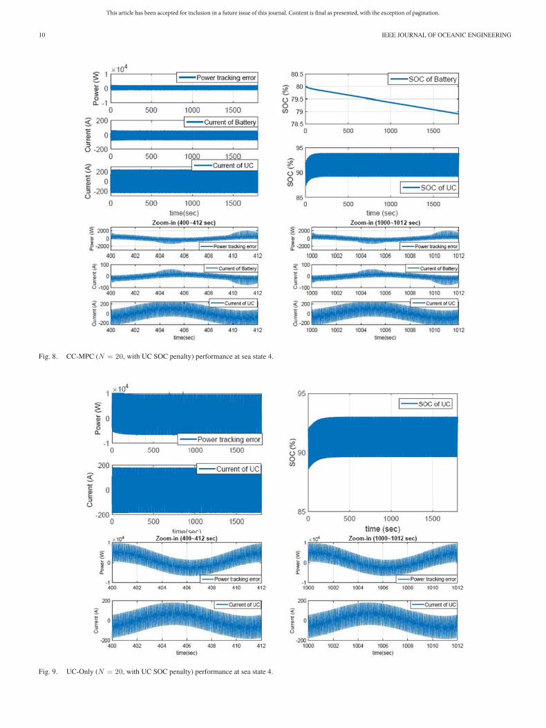
where SOCUC-D is the desired SOC of UC. Compared to thezoom-in plots in Fig. 7, the zoom-in plots in Fig. 8 show thatthis penalty γUCSOC maintains the tracking error and the outputcurrent of the batteries during the 1000–1012-s time frame sameas those during the 400–412-s time frame.
With proper coordination, the usable energy stored in anHESS system mainly depends on the battery, so the penalty
on the UC SOC changing has almost no impact on the totalusable energy in the HESS system. For a fair comparison, thesame penalty is also added into the cost function of PF-MPC.However, this is not possible for a UC-Only system, becausethere is no battery to maintain the UC at a high SOC level.Therefore, for UC-Only, the penalty (28) is not included, other-wise extremely large error will be caused on power tracking, asshown in Fig. 9 as compared with Fig. 8.
To summarize, the cost functions (21) and (25) are integratedwith (28) to obtain the new cost functions as follows:
LHESS(x(k), u(k)) = λTracking(PFL(k) − PB (k) − PUC(k))2
+ λLoss(NB RB u21(k) + NUCRUCu2
2(k))
+ γUCSOC(x2(k) − SOCUC-D)2 (29)
LUC(x2(k), u2(k)) = λTracking(PFL−High(k) − PUC(k))2
+ λLoss(NUCRUCu22(k))
+ γUCSOC(x2(k) − SOCUC-D)2 (30)
where λTracking ∈ [0, 1], λLoss ∈ [0, 1], and γUCSOC are the powertracking error penalty, the energy loss penalty, and UC SOCchanging penalty, respectively; and λTracking + λLoss = 1.
The weighting factors allow us to put different emphasis oneach attribute to investigate the performance tradeoff. By vary-ing λ ∈ [0, 1], λTracking ∈ [0, 1], λLoss ∈ [0, 1], and γUCSOC , theUC-Only (26), the PF-MPC (22)–(24), and the CC-MPC (20)problems are solved at sea states 4 and 6, respectively. Two case
This article has been accepted for inclusion in a future issue of this journal. Content is final as presented, with the exception of pagination.
10 IEEE JOURNAL OF OCEANIC ENGINEERING
Fig. 8. CC-MPC (N = 20, with UC SOC penalty) performance at sea state 4.
Fig. 9. UC-Only (N = 20, with UC SOC penalty) performance at sea state 4.

This article has been accepted for inclusion in a future issue of this journal. Content is final as presented, with the exception of pagination.
HOU et al.: MITIGATING POWER FLUCTUATIONS IN ELECTRIC SHIP PROPULSION WITH HYBRID ENERGY STORAGE SYSTEM 11
Fig. 10. Pareto fronts of UC-Only, CC-MPC, and PF-MPC at sea state4 (N = 20).
Fig. 11. Pareto fronts of UC-Only, CC-MPC, and PF-MPC at sea state6 (N = 20).
studies are performed in Sections V-B and V-C. The first studyfor the balanced torque case, namely, the worst case scenariopresented earlier, is defined as “Case I.” The second case study,where the rotational speed is regulated by a PI controller, isdefined as “Case II.”
B. Case I: Performance Tradeoff Analysis
In this case study, UC-Only, PF-MPC, and CC-MPC are eval-uated at different sea states. The Pareto fronts of these threesolutions, which represent the best achievable performance forthe system with HESS and only UCs, are shown in Figs. 10 and11 with the predictive horizon N = 20. The results indicate thatthe CC-MPC has substantial advantages over the PF-MPC and
UC-Only configuration, in terms of mitigating the load powerfluctuations and reducing losses at both sea state 4 and 6. Notethat the constraints are not active in these simulation results.However, after a long self-sustained operation period, the con-straint of SOC of the battery will become active. MPC is ableto guarantee the battery working within the constraints. Theperformance might be degraded, however, so it is suggested torecharge the HESS before the battery reaches its constraints.
The key observations are summarized in the followingremarks.
Remark 5.1: The Pareto fronts give insights into the effec-tiveness of HESS with MPC and the tradeoff between the track-ing RMS error and the HESS losses. As shown in Figs. 10 and11, the CC-MPC strategy has substantial advantages on trackingerror mitigation, compared with the energy storage system withonly UCs. Furthermore, the CC-MPC strategy is able to reducethe tracking RMS error without significant increase in losses atboth sea states 4 and 6, compared with the PF-MPC strategy.
Remark 5.2: A proper control strategy is the critical enablerfor capitalizing the benefits of HESS. As can be seen fromFigs. 10 and 11, UC only can do as well as (and even betterthan) the HESS if PF-MPC is used. Without proper coordination,HESS does not have convincing performance advantage.
Remark 5.3: Under CC, the battery will properly charge theUC to keep it working at an efficient range to achieve a desiredtracking performance with high efficiency, as shown in Fig. 12(b). In contrast, without the coordination, the UC cannot assistthe battery to reduce the losses, and the battery cannot prop-erly charge the UC when needed, leading to the shortened self-sustained operation time and degraded performance, as shownin Fig. 12(a). The large variation of the SOC of UC is observedin Fig. 12(b), compared with that in Fig. 12(a), because the UCin the CC-MPC must deal with both high- and low-frequencyfluctuations, but the UC in the PF-MPC only addresses high-frequency fluctuations. Therefore, the UC in the CC-MPC isused more efficiently than that in the PF-MPC. Furthermore,the high-frequency fluctuations in the PF-MPC are not reducedto the level achieved by CC-MPC, as shown in Fig. 12(b) be-cause of the penalty of the UC SOC in (30). Without this penalty,the SOC of UC in PF-MPC will decrease fast, and the trackingperformance will deteriorate. Moreover, only when the UC isoperating at high current levels will the batteries in the CC-MPCstrategy start to work to assist in reducing the power tracking er-ror and minimizing the losses, as shown in Fig. 12(d). However,with PF, the battery and UC can be working at cross purposes;namely, when one is charging the other may be discharging.This causes additional losses and degrades power tracking per-formance, as shown in Fig. 12(c). Consequently, the overallenergy consumed in the PF-MPC, as shown in Fig. 12(a), ismuch more than that in the CC-MPC shown in Fig. 12(b).
Remark 5.4: Extending the predictive horizon will gener-ally improve performance, at the cost of increased computa-tional complexity. To make the proposed solution feasible forreal-time implementation, a short predictive horizon is used.A sensitivity analysis of the predictive horizon for CC-MPCis performed to gain insights into the tradeoff between thesedesign attributes. As shown in Figs. 13 and 14, the performance

This article has been accepted for inclusion in a future issue of this journal. Content is final as presented, with the exception of pagination.
12 IEEE JOURNAL OF OCEANIC ENGINEERING
Fig. 12. PF-MPC and CC-MPC performance at sea state 4. (a) PF-MPC. (b) CC-MPC. (c) PF-MPC HESS current (zoom in).(d) CC-MPC HESS current (zoom in).
Fig. 13. Sensitivity analysis of predictive horizon for CC-MPC at sea state 4.
is relatively insensitive to the predictive horizon for this problem.Using a relatively short predictive horizon (N = 5–20), one canachieve similar performance achieved by the offline block MPCsolution (N = 100). It is worth noting that the receding hori-zon MPC (N = 10–20) can achieve better performance than theblock MPC (N = 100) at sea state 4, as shown in Fig. 13, dueto the closed-loop control with feedback in the receding horizonMPC. Given that the required computational time depends on
Fig. 14. Sensitivity analysis of predictive horizon for CC-MPC at sea state 6.
not only the algorithm, but also the computation hardware, thisstudy does not directly prove real-time feasibility. Neverthe-less, by establishing the evidence that a long prediction horizonis not needed for this problem, it provides strong support thatan MPC-based solution can be practical. Moreover, this sen-sitivity analysis provides insight that helps designers managethe tradeoff between performance and control complexity. Asan example, the CC-MPC (N = 20) has been implemented on

This article has been accepted for inclusion in a future issue of this journal. Content is final as presented, with the exception of pagination.
HOU et al.: MITIGATING POWER FLUCTUATIONS IN ELECTRIC SHIP PROPULSION WITH HYBRID ENERGY STORAGE SYSTEM 13
Fig. 15. Pareto-fronts of Cases I and II at sea state 4 (N = 20).
a Speedgoat real-time controller (Processor: Intel Core i5-6803.6 GHz; Memory: DDR3 4096 MB), and the average task exe-cution time (TET) is 10.2 μs and the maximum TET is 22.2 μs,much smaller than the sampling time of 20 ms.
Remark 5.5: The major limitation of UC-Only is its low en-ergy density, which can only maintain a very short self-sustainedoperation time. In this paper, the generator is assumed to oper-ate at its optimal point and provide the constant power, and theload power fluctuations are compensated by the HESS withoutinvolving the main generator. UC-Only performance could beimproved if the generator is used continuously to charge UCs.We will explore this in our future work.
C. Case II: Performance Tradeoff Analysis
To evaluate the effectiveness of the proposed solution, an-other case study is performed, where the rotational speed isregulated by a PI controller. The PI controller for the speed reg-ulation is developed and tuned based on the algorithm given in[6, Appendix B.1]: KP = (1/a)(Is/Tsum) and KI = KP /Ti ,where a = 3 is a constant related to the damping ratio,Is = 4800 kg ·m2 is the total propeller rotational inertia, Tsum =0.011 s is the lumped time constant of the motor and the shaftspeed sensor filter, and Ti = 0.1 s is the PID controller integraltime constant. Since the high-frequency fluctuations are signifi-cantly filtered in Case II, the batteries, instead of UCs, are usedas the single type of energy storage. The number of batterymodules is set at 18, as shown in Table V. This “battery only”configuration is defined as “B-Only” in this case study.
The Pareto fronts of Cases I and II are shown in Figs. 15 and16. The key observations are summarized in Remark 5.6.
Remark 5.6: As shown in Figs. 15 and 16, the performanceof PF-MPC in Case II is even worse than that in Case I.The reason for this can be explained as follows: The high-frequency power fluctuation in Case II is around 40% of thatin Case I, due to the lowpass filter effect of the inertia andthe speed controller in Case II. However, the low-frequencypower fluctuations are almost the same, which means the losses
Fig. 16. Pareto-fronts of Case I and II at sea state 6 (N = 20).
Fig. 17. HESS output currents of CC-MPC (Case II) at sea state 4.
of batteries∑NT
k=0(Powerbattery-loss(k)) are almost the same un-der the PF-MPC strategy. Because the losses of batteries aredominant among the total losses
∑NT
k=0(Powerbattery-loss(k) +PowerUC-loss(k)), the performance metric
Loss %
=∑NT
k=0(Powerbattery-loss(k) + PowerUC-loss(k))∑NT
k=0 |PDemand(k)| × 100%
gets worse as the total command power decreases. On the otherhand, the performance of CC-MPC in Case II is better than thatin Case I at both sea states 4 and 6, as UCs with CC-MPC notonly cancel out the high-frequency fluctuations, but also help indealing with the low-frequency fluctuations, as shown in Fig. 17.As can be seen, the output currents of batteries and UCs are bothreduced, as shown in Fig. 17, compared to Fig. 12(d), whichindicates that the total HESS losses are significantly reducedand the battery life is extended. Compared to B-Only in Figs. 15and 16, CC-MPC outperforms B-Only at both sea states 4 and

This article has been accepted for inclusion in a future issue of this journal. Content is final as presented, with the exception of pagination.
14 IEEE JOURNAL OF OCEANIC ENGINEERING
6. This result provides the insight that even though the high-frequency fluctuations are significantly filtered, with a properstrategy, UC is still essential to improve performance in termsof minimizing tracking error and losses. In summary, Case IIalso demonstrates the effectiveness of the proposed strategyCC-MPC under more realistic conditions.
VI. CONCLUSION
This paper proposes a new solution to address the effectsof power fluctuations in an electric ship propulsion system:an HESS that enables internal energy cycling and coordinatedenergy management. To capture the underlying dynamic behav-ior of ship propulsion systems, a propeller and ship dynamicmodel is developed to support the exploration of HESS so-lutions. According to the frequency characteristics of powerfluctuations, CC and PF control strategies are investigated. TheMPC is formulated based on the MOP to minimize the trackingrms error and HESS losses. The single type of energy storage isalso studied to provide a benchmark in characterizing the per-formance of HESS. For the energy management of HESS, twoMPC-based strategies, CC-MPC and PF-MPC, are designedand evaluated. The comparison results indicate that the CC-MPC strategy outperforms the PF-MPC strategy in terms ofpower tracking, HESS efficiency, and self-sustained operationtime. The sensitivity analysis of the predictive horizon for theCC shows the feasibility of the MPC-based strategies for real-time applications. In summary, CC is preferred to mitigate theshipboard load power fluctuation with HESS, given its superiorperformance and ability in trading off between achieving powertracking and reducing energy losses.
This study establishes a foundation for future work in pushingthis technology forward. We will focus on developing reliablepower prediction models for both regular and irregular waves,enhancing performance and robustness of the solution, and val-idating real-time implementation. Meanwhile, a life-cycle costanalysis of the HESS for shipboard power is also of interestand importance, and will be performed. It is also worth not-ing that there are other multifrequency load fluctuation applica-tions, such as pulse power loads (load periods in microseconds),drilling rigs with heave compensators (load periods in seconds),thrusters in irregular sea (load periods in tens of seconds) andso on, when a coordinated HESS could provide advantages.
ACKNOWLEDGMENT
The authors would like to thank the editor and reviewers fortheir valuable feedback.
REFERENCES
[1] N. Doerry, “Naval power system technology development roadmap,”Electric Ships Office, SEA 05, 2007.
[2] J. Kuseian, “Naval power system technology development roadmap,”Electric Ships Office, PMS 320, 2013.
[3] J. McCarthy, “On the calculation of thrust and torque fluctuations ofpropellers in non-uniform wake flow,” Hydromech. Lab., Washington,DC, USA, Res. Dev. Rep. no. 1533, Oct. 1961.
[4] K. Koushan, “Dynamics of propeller blade and duct loading on ventilatedthrusters in dynamic positioning mode,” in Proc. Dyn. Positioning Conf.,Houston, TX, USA, Oct. 9–10, 2007, pp. 1–13.
[5] P. Liu, M. Islam and B. Veitch, “Some unsteady propulsive characteristicsof a podded propeller unit under maneuvering operation,” in Proc. 1st Int.Symp. Marine Propulsors, Trondheim, Norway, Jun. 2009, pp. 507–516.
[6] Ø. N. Smogeli, “Ventilated thrusters in dynamic positioning mode controlof marine propellers from normal to extreme conditions,” Ph.D. disserta-tion, Dept. Marine Technol., Norwegian Univ. Sci. Technol., Trondheim,Norway, 2006.
[7] D. Radan, “Integrated control of marine electrical power systems,” Ph.D.dissertation, Dept. Marine Technol., Norwegian Univ. Sci. Technol.,Trondheim, Norway, 2008.
[8] T. Perez et al., “An overview of the marine systems simulator (MSS): Asimulink toolbox for marine control systems,” Model., Identif., Control,vol. 27, no. 4, pp. 1–13, 2006.
[9] A. J. Sørensen and Ø. N. Smogeli, “Torque and power control of elec-trically driven marine propellers,” Control Eng. Pract., vol. 17, no. 9,pp. 1053–1064, 2009.
[10] Ø. N. Smogeli and A. J. Sørensen, “Antispin thruster control for ships,”IEEE Trans. Control Syst. Technol., vol. 17, no. 6, pp. 1362–1375,Nov. 2009.
[11] Ø. N. Smogeli, A. J. SØrensen, and K. J. Minsaas, “The concept of anti-spin thruster control,” Control Eng. Pract., vol. 16, no. 4, pp. 465–480,2008.
[12] J. Hou, J. Sun, and H. Hofmann, “Mitigating power fluctuations in elec-trical ship propulsion using model predictive control with hybrid energystorage system,” in Proc. Amer. Control Conf., 2014, pp. 4366–4371.
[13] J. Hou et al., “Modeling and test-bed development for an electric drivesystem with hybrid energy storage,” in Proc. Electr. Mach. Technol. Symp.,2014.
[14] A. C. Takinaci and M. Atlar, “Performance assessment of a concept propul-sor: The thrust-balanced propeller,” Ocean Eng., vol. 29, no. 2, pp. 129–149, 2002.
[15] A. Jaafar et al., “Sizing and energy management of a hybrid locomotivebased on flywheel and accumulators,” IEEE Trans. Veh. Technol., vol. 58,no. 8, pp. 3947–3958, Oct. 2009.
[16] Z. Song et al., “Energy management strategies comparison for electricvehicles with hybrid energy storage system,” Appl. Energy, vol. 134,pp. 321–331, 2014.
[17] A. Florescu et al., “Adaptive frequency-separation-based energymanagement system for electric vehicles,” J. Power Sources, vol. 280,pp. 410–421, 2015.
[18] M. M. Bernitsas, “Kt, Kq and efficiency curves for the wageningenb-series propellers,” Univ. Michigan, Ann Arbor, MI, USA, Tech. Rep.no. 237, 1981.
[19] HydroComp, Inc., Durham, NH, USA, “Correlating propeller perfor-mance with Kt/Kq multipliers,” Tech. Rep. no. 101, 2003.
[20] J. Carlton, Marine Propellers and Propulsion, 3rd ed. Amsterdam, TheNetherlands: Elsevier, 2012.
[21] K. J. Rawson, Basic Ship Theory, 5th ed. Amsterdam, The Netherlands:Elsevier, 2002.
[22] Z. Li, “Path following with roll constraints for marine surface vesselsin wave fields,” Ph.D. dissertation, Dept. Marine Eng. Naval Architect.,Univ. Michigan, Ann Arbor, MI, USA, 2009.
[23] R. L. Beck and J. Wolfe, “Developing a ship motions prediction programusing linear theory for a ship maneuvering through a seaway,” Univ.Michigan, Ann Arbor, MI, USA, Tech. Rep. no. 076, 2007.
[24] D. Peng, “Propeller design report,” Shanghai Jiao Tong University, Shang-hai, China, Tech. Rep., 2009.
[25] 2015. [Online]. Available: http://www. evamerica.com/fluxpbcell072811.pdf
[26] 2015. [Online]. Available: http://www.maxwell.com/products/ultracapacitors/125v-tran-modules/documents
[27] E. F. Camacho and C. Bordons, Model Predictive Control, 2nd ed. NewYork, NY, USA: Springer-Verlag, 2013.
[28] J. B. Rawlings and D. Q. Mayne, Model Predictive Control: Theory andDesign, 1st ed. San Francisco, CA, USA: Nob Hill, 2009.
[29] D. Q. Mayne, “Model predictive control: Recent developments and futurepromise,” Automatica, vol. 50, no. 12, pp. 2967–2986, 2014.
[30] J. Sun, I. V. Kolmanovsky, R. Ghaemi and S. Chen, “A stable block modelpredictive control with variable implementation horizon,” Automatica, vol.43, no. 11, pp. 1945–1953, 2007.

This article has been accepted for inclusion in a future issue of this journal. Content is final as presented, with the exception of pagination.
HOU et al.: MITIGATING POWER FLUCTUATIONS IN ELECTRIC SHIP PROPULSION WITH HYBRID ENERGY STORAGE SYSTEM 15
Jun Hou (S’15) received the M.S. degree in electricalengineering from Northeastern University, Shenyang,China, in 2011. He is currently working toward thePh.D. degree in electrical engineering and computerscience at the University of Michigan, Ann Arbor,MI, USA.
His current research interests include integra-tion, modeling, control, and optimization of hybridenergy storage, power electronic converters, and elec-tric propulsion systems.
Jing Sun (M’89–SM’00–F’04) received the Bache-lor’s and Master’s degrees in electrical engineeringfrom the University of Science and Technology ofChina, Hefei, China, in 1982 and 1984, respectively,and the Ph.D. degree in electrical engineering fromthe University of Southern California, Los Angeles,CA, USA, in 1989.
She is the Michael G. Parsons Professor of en-gineering at the University of Michigan, Ann Arbor,MI, USA. From 1989 to 1993, she was an AssistantProfessor in the Electrical and Computer Engineering
Department at Wayne State University, Detroit, MI. She joined Ford ResearchLaboratory in 1993, where she worked on advanced powertrain system con-trols. After spending almost ten years in industry, she came back to academiain 2003 and joined the Naval Architecture and Marine Engineering Departmentat the University of Michigan. She also has joint appointments in the ElectricalEngineering and Computer Science Department as well as the Mechanical En-gineering Department at the same university. She holds 39 U.S. patents and hascoauthored (with Petros Ioannou) a textbook on Robust Adaptive Control. Shehas published more than 200 archived journal and conference papers.
Dr. Sun received the 2003 IEEE Control System Technology Award.
Heath F. Hofmann (S’90–M’92–SM’16) receivedthe Ph.D. degree in electrical engineering and com-puter science from the University of California atBerkeley, Berkeley, CA, USA, in 1998.
He is currently an Associate Professor with theUniversity of Michigan, Ann Arbor, MI, USA. Hehas authored approximately four dozen papers inrefereed journals. He currently holds 14 patents. Hisresearch interests include power electronics, special-izing in the design, simulation, and control of elec-tromechanical systems, adaptive control techniques,
energy harvesting, flywheel energy storage systems, electric and hybrid electricvehicles, and finite-element analysis.
![IEEE JOURNAL OF OCEANIC ENGINEERING 1 Peer-Reviewed ...rizzini/papers/simetti18joe.pdf · exploitedforresourcegathering[2],monitoringandexploration ofarchaeologicalsites[3],andsecurityapplications[4]toname](https://img.dokumen.tips/doc/110x75/5fd5b89a87747e213733bc82/ieee-journal-of-oceanic-engineering-1-peer-reviewed-rizzinipapers-exploitedforresourcegathering2monitoringandexploration.jpg)


![IEEE JOURNAL OF OCEANIC ENGINEERING 1 Kinematics and ...faculty.washington.edu/jmt3rd/SWIFTdata/Newport/... · breakingwaves inthefield[17].Breakerswereidentified based on rapid](https://img.dokumen.tips/doc/110x75/5eda5a6eb3745412b57133aa/ieee-journal-of-oceanic-engineering-1-kinematics-and-breakingwaves-intheield17breakerswereidentiied.jpg)