Embed Size (px)
DESCRIPTION
This guide principally provides guidance for the interconnection of user-owned substations. In this regard onlymedium- and high-voltage purchased-power interconnections are addressed, since low-voltage (and some mediumvoltage)interconnections for typical residential, commercial, and small industrial energy purchase are adequatelycovered by existing electric utility practices and standards.
Citation preview

IEEE Std 1109-1990
IEEE Guide for the Interconnection of User-Owned Substations to Electric Utilities
SponsorSubstations Committeeof theIEEE Power Engineering Society
Approved May 31, 1990
IEEE Standards Board
Approved October 12, 1990
American National Standards Institute
Abstract: IEEE Std 1109-1990, IEEE Guide for the Interconnection of User-Owned Substations to ElectricUtilities, provides a checklist and selected guidance, for persons not normally practicing in this specializedfield, of major technical design areas that should be considered when interconnecting user-owned andutility-owned facilities at substations. Only medium- and high-voltage purchased-power interconnectionsare addressed. This guide does not discuss the considerable implications of interactive power systemsdesign and operation, nor does it present criteria or directions for the design of substations.Keywords: high-voltage purchased-power interconnections, interconnections, medium-voltagepurchased-power interconnections, non-utility generation, substations, user-owned and utility-ownedfacilities at substations
ISBN 1-55937-041-6
Copyright © 1990 by
The Institute of Electrical and Electronics Engineers, Inc.
345 East 47th Street, New York NY 10017-2394, USA
No part of this publication may be reproduced in any form, in an electronic retrieval system or otherwise, without theprior written permission of the publisher.

ii
IEEE Standards documents are developed within the Technical Committees of the IEEE Societies and the StandardsCoordinating Committees of the IEEE Standards Board. Members of the committees serve voluntarily and withoutcompensation. They are not necessarily members of the Institute. The standards developed within IEEE represent aconsensus of the broad expertise on the subject within the Institute as well as those activities outside of IEEE that haveexpressed an interest in participating in the development of the standard.
Use of an IEEE Standard is wholly voluntary. The existence of an IEEE Standard does not imply that there are no otherways to produce, test, measure, purchase, market, or provide other goods and services related to the scope of the IEEEStandard. Furthermore, the viewpoint expressed at the time a standard is approved and issued is subject to changebrought about through developments in the state of the art and comments received from users of the standard. EveryIEEE Standard is subjected to review at least every five years for revision or reaffirmation. When a document is morethan five years old and has not been reaffirmed, it is reasonable to conclude that its contents, although still of somevalue, do not wholly reflect the present state of the art. Users are cautioned to check to determine that they have thelatest edition of any IEEE Standard.
Comments for revision of IEEE Standards are welcome from any interested party, regardless of membership affiliationwith IEEE. Suggestions for changes in documents should be in the form of a proposed change of text, together withappropriate supporting comments.
Interpretations: Occasionally questions may arise regarding the meaning of portions of standards as they relate tospecific applications. When the need for interpretations is brought to the attention of IEEE, the Institute will initiateaction to prepare appropriate responses. Since IEEE Standards represent a consensus of all concerned interests, it isimportant to ensure that any interpretation has also received the concurrence of a balance of interests. For this reasonIEEE and the members of its technical committees are not able to provide an instant response to interpretation requestsexcept in those cases where the matter has previously received formal consideration.
Comments on standards and requests for interpretations should be addressed to:
Secretary, IEEE Standards Board445 Hoes LaneP.O. Box 1331Piscataway, NJ 08855–1331USA
IEEE Standards documents are adopted by the Institute of Electrical and Electronics Engineers without regard towhether their adoption may involve patents on articles, materials, or processes. Such adoption does not assumeany liability to any patent owner, nor does it assume any obligation whatever to parties adopting the standardsdocuments.

iii
Foreword
(This Foreword is not a part of IEEE Std 1109-1990 , IEEE Guide for the Interconnection of User-Owned Substations to ElectricUtilities.)
This guide provides a “checklist” and selected guidance, for persons not normally practicing in this specialized field,on topics that should be considered when developing the interconnection of user-owned and electric-utility-ownedelectric power facilities, particularly substations. This guide is concerned with large substations for purchased-power-only service and also with substations of all sizes associated with the interconnection of user-owned generating(interactive power, dispersed power, cogeneration, or small-power-producer) facilities.
This guide is concerned with generation (interactive electrical system) interconnections of all magnitudes to the degreethat the substation facilities are affected. However, it is not within the scope of this guide to discuss in detail theconsiderable implications of interactive power systems design and operations, since these are covered in otherdocuments.
A listing of code and standard agencies relevant to substation design is included in the Appendix.
This guide was prepared by Working Group D-6 of the Distribution Substations Subcommittee of the IEEE PowerEngineering Society Substations Committee. The following persons were members of Working Group D-6:
Theodore J. Kolenda, Chair
Mark CarpenterDavid L. GarrettDavid L. Harris
Irving H. KoponenPhilip R. NanneryRaymond J. Perina
Donald R. Schafer
Acknowledgment: Angela T. Taylor
The following persons were on the balloting committee that approved this document for submission to the IEEEStandards Board:
W. AckermanB. Y. AfsharS. J. ArnotN. BarbeitoJ. D. BetzK. L. BlackC. J. BlattnerW. R. BlockR. J. BowerS. D. BrownD. E. BuettnerJ. B. CannonS. ClutsE. F. CounselP. DanforsF. A. DenbrockW. K. DickC. C. DiemondP. R. DolanL. N. FergusonD. L. GarrettH. R. GildenJ. GrzanA. Habin
N. G. HingoraniJ. E. HolladayM. L. HolmD. C. JohnsonG. KaradyJ. J. KeaneR. P. KeilF. F. KlugeD. F. KoenigT. J. KolendaA. E. KollarI. R. KoponenL. W. Kurtz, Jr.K. C. LabbeD. N. LairdL. M. LaskowskiA. F. LeiboldK. E. LewisC. T. LindenbergP. H. LipsW. F. LongR. MatulicT. S. McLenahanS. P. Meliopoulis
P. R. NanneryJ. O’HaraJ. T. OrrellJ. OswaldJ. PaolozziS. G. PatelR. J. PerinaT. A. Pinkham, IIIJ. QuinataD. G. RishworthB. D. RussellJ. SabathD. R. SchaferR. C. St. ClairJ. G. SverakW. K. SwitzerE. R. TaylorH. M. TuckerL. F. Volf, Jr.R. J. WehlingW. M. WernerR. W. WrayR. M. Youngs

iv
When the IEEE Standards Board approved this standard on May 31, 1990, it had the following membership:
Marco W. Migliaro, Chair James M. Daly, Vice Chair
Andrew G. Salem, Secretary
Dennis BodsonPaul L. BorrillFletcher J. BuckleyAllen L. ClappStephen R. DillonDonald C. FleckensteinJay Forster*Thomas L. Hannan
Kenneth D. HendrixJohn W. HorchJoseph L. Koepfinger*Irving KolodnyMichael A. LawlerDonald J. LoughryJohn E. May, Jr.Lawrence V. McCall
L. Bruce McClungDonald T. Michael*Stig NilssonRoy T. OishiGary S. RobinsonTerrance R. WhittemoreDonald W. Zipse
*Member Emeritus

v
CLAUSE PAGE
1. Introduction and Scope .......................................................................................................................................7
2. Definitions and References .................................................................................................................................8
2.1 Definitions.................................................................................................................................................. 82.2 References.................................................................................................................................................. 8
3. System Interconnection Considerations..............................................................................................................9
3.1 Voltage, Voltage Range, Frequency, and Frequency Range ..................................................................... 93.2 Phase Rotation and Phase Position .......................................................................................................... 103.3 Fault Interrupting and Momentary Ratings.............................................................................................. 103.4 Continuous Ratings .................................................................................................................................. 103.5 Types of Service....................................................................................................................................... 103.6 Load and Power-Factor Considerations ................................................................................................... 11
4. Substation Configuration ..................................................................................................................................12
4.1 Breaker Arrangement ............................................................................................................................... 124.2 Power Transformer Connections ............................................................................................................. 164.3 Switch and Bus Construction................................................................................................................... 174.4 Interconnecting Lines Location and Orientation ..................................................................................... 174.5 Control Building ...................................................................................................................................... 174.6 Future Expansion Consideration.............................................................................................................. 18
5. Interactive Power (User-Owned Generation) Considerations ..........................................................................18
5.1 Synchronizing .......................................................................................................................................... 185.2 Startup/Auxiliary Power .......................................................................................................................... 185.3 Generator Grounding ............................................................................................................................... 185.4 Generator Characteristics ......................................................................................................................... 195.5 Reactive Capability .................................................................................................................................. 195.6 Isolating Switch........................................................................................................................................ 19
6. Substation Facilities Design..............................................................................................................................20
6.1 Grounding ................................................................................................................................................ 206.2 Insulation Levels (BIL)............................................................................................................................ 206.3 Clearances and Access ............................................................................................................................. 206.4 Lighting.................................................................................................................................................... 206.5 Lightning (Surge) Protection ................................................................................................................... 206.6 Transmission (or Distribution) Line Termination.................................................................................... 216.7 Switching Equipment............................................................................................................................... 216.8 Instrument Transformers.......................................................................................................................... 216.9 Cable Systems .......................................................................................................................................... 21
7. Protective Relaying ...........................................................................................................................................22
7.1 Line Protection......................................................................................................................................... 227.2 Transformer Protection ............................................................................................................................ 227.3 Bus Protection .......................................................................................................................................... 227.4 Synchronizing/Synchronism Check......................................................................................................... 22

vi
CLAUSE PAGE
7.5 Reclosing and Transfer Tripping ............................................................................................................. 227.6 Load Shedding and “Islanding” ............................................................................................................... 227.7 Generator Protection ................................................................................................................................ 237.8 Relaying Interfaces and Interlocks........................................................................................................... 23
8. Metering and Instrumentation...........................................................................................................................23
8.1 Revenue Metering .................................................................................................................................... 238.2 Indicating Instruments and Status ............................................................................................................ 238.3 Telemetering ............................................................................................................................................ 24
9. Control and Communications ...........................................................................................................................24
9.1 Local Control ........................................................................................................................................... 249.2 Supervisory Control ................................................................................................................................. 249.3 Remote Dispatch ...................................................................................................................................... 259.4 Communications ...................................................................................................................................... 259.5 Communication Circuit Protection .......................................................................................................... 25
10. Maintenance and Operation ..............................................................................................................................25
10.1 Coordination of Switching ....................................................................................................................... 2510.2 Tagging, Lockout, and Grounding........................................................................................................... 2610.3 Personnel Safety and Training ................................................................................................................. 2610.4 Access ...................................................................................................................................................... 2610.5 Testing...................................................................................................................................................... 2610.6 Emergency Conditions ............................................................................................................................. 26
11. Administrative Items.........................................................................................................................................26
12. Contractual Documents.....................................................................................................................................27
Annex (Informative) .....................................................................................................................................................28
Copyright 1990 IEEE All Rights Reserved 7
IEEE Guide for the Interconnection of User-Owned Substations to Electric Utilities
1. Introduction and Scope
This guide presents a “checklist” of major technical design areas that should be considered when interconnecting user-owned and utility-owned facilities at substations. Guidance is presented in selected areas of particular importance.
This guide principally provides guidance for the interconnection of user-owned substations. In this regard onlymedium- and high-voltage purchased-power interconnections are addressed, since low-voltage (and some medium-voltage) interconnections for typical residential, commercial, and small industrial energy purchase are adequatelycovered by existing electric utility practices and standards.
Historically, most utilities with a significant industrial base load have established technical guidelines for largepurchasers of electric energy when the user’s demand mandates the construction of a medium- or high-voltagesubstation having a capacity greater than 500 kVA and connected to a three-phase power interconnection with avoltage greater than 15 kV. These substation and interconnection facilities were usually for the user purchase ofelectric power only. The presence of a user’s own in-house generation facility was uncommon enough to be handled ona case-by-case basis.
The advent of the Public Utilities Regulatory Policies Act (PURPA) of 1978, as well as other public laws, hasprecipitated the development of numerous new electric power generating facilities that are necessarily interconnectedto established electric utilities. It is common for these “dispersed” facilities to be fostered by entrepreneurialorganizations that may or may not be cognizant of the complexities associated with connecting to and interacting witha large electric system by means of a dedicated substation facility, such as is addressed by this document. Therefore,this guide does address in general the interconnection of interactive (dispersed generation, cogeneration, and small-power producer) facilities of all sizes with electric utilities, to the degree that the interconnection substation design isaffected. However, the subject of interactive power systems is addressed in greater detail in the publications of otheragencies or committees.
It is not the intent of this guide to present detailed design criteria or directions. And it is beyond the scope of thisdocument to discuss commercial or contractual issues, which are covered by other existing industry codes, standards,and practices. Also, detailed discussions of the design and operation of interactive power systems (cogeneration,dispersed power, small power producers; and user-owned generation) are not included, since it would be beyond thescope of this document and since these topics are covered by other existing or forthcoming documents.

8 Copyright 1990 IEEE All Rights Reserved
IEEE Std 1109-1990 IEEE GUIDE FOR THE INTERCONNECTION OF USER-OWNED
A listing of related code and standard agencies is included as an appendix to aid the users of this guide in finding othercodes and standards applicable to the design, operation, and equipment selection of proposed interconnectionsubstations.
2. Definitions and References
2.1 Definitions
cogeneration: The generation of electric energy and commercial or industrial quality heat or steam from a singlefacility.
dispersed power: An electric power generation source (or sources) not directly under established electric utilityownership and control.
electrical system: The existing utility network consisting of interconnected and synchronized generation,transmission, and distribution facilities.
generation: The production or storage, or both, of electric energy with the intent of enabling practical use ofcommercial sale of the available energy. This includes photovoltaic, wind-farm, hydro, etc., as well as normalcommercial and industrial thermal sources.
interactive electrical systems: Two or more interconnected and compatible electrical systems with appropriateprotection and measuring provisions at their interconnection point(s).
interconnection: The physical plant and equipment required to facilitate the transfer of electric energy between twoor more entities. It can consist of a substation and an associated transmission line and communications facilities oronly a simple electric power feeder.
small-power producer: A non-utility generation source that is a qualifying small-power production facility underPURPA and the Federal Energy Regulatory Commission (FERC).
user (or customer): The independent party that may be a purchaser of utility electric power or a producer of electricenergy for sale to an electric utility or both.
2.2 References
This guide shall be used in conjunction with the following publications. When the following standards are supersededby an approved revision, the revision shall apply.
[1] ANSI C2-1990 National Electrical Safety Code.1
[2] ANSI C84.1-1989 Voltage Ratings for Electric Power Systems and Equipment (60 Hz).
[3] IEEE Std C37.1-1987 IEEE Standard Definition, Specification, and Analysis of Systems Systems Used forSupervisory Control, Data Acquisition, and Automatic Control (ANSI).2
[4] IEEE Std C37.2-1987 IEEE Standard Electrical Power System Device Function Numbers (ANSI).
[5] IEEE Std C37.122-1983 IEEE Standard Gas-Insulated Substations (ANSI).
[6] IEEE Std 80-1986 IEEE Guide for Safety in AC Substation Grounding (ANSI).
1ANSI publications are available from the Sales Department, American National Standards Institute, 1430 Broadway, New York, NY 10018, USA.2IEEE publications are available from the Institute of Electrical and Electronics Engineers, Service Center, 445 Hoes Lane, Piscataway, NJ 08855-1331, USA.

Copyright 1990 IEEE All Rights Reserved 9
SUBSTATIONS TO ELECTRIC UTILITIES IEEE Std 1109-1990
[7] IEEE Std 81-1983 IEEE Guide for Measuring Earth Resistivity, Ground Impedance, and Earth Surface Potentialsof a Ground System (ANSI).
[8] IEEE Std 525-1987 IEEE Guide for the Design and Installation of Cable Systems in Substations (ANSI).
[9] IEEE Std 605-1987 IEEE Guide for Design of Substation Rigid-Bus Structures (ANSI).
[10] IEEE Std 979-1984 IEEE Guide for Substation Fire Protection (ANSI).
[11] IEEE Std 980-1987 IEEE Guide for Containment and Control of Oil Spills in Substations (ANSI).
[12] IEEE P998 (Draft) Guide for Direct Lighting Stroke Shielding of Substations.3
[13] IEEE Std 1001-1988 IEEE Guide for Interfacing Dispersed Storage and Generation Facilities With ElectricUtility Systems (ANSI).
[14] IEEE Std 1119-1988 IEEE Guide for Fence Safety Clearances in Electric-Supply Stations (ANSI).
[15] IEEE P1127 (Draft) Guide for the Design, Construction, and Operation of Safe and Reliable Substations forEnvironmental Acceptance.4
[16] NFPA 70-1990, National Electrical Code (ANSI).5
3. System Interconnection Considerations
Whether a proposed interconnection is for an interactive (i.e., including user-owned generation) or purchased-energy-only facility, the following significant design factors should be considered for the high-voltage electric powerinterface. Care should be taken to ensure that each party of the interconnection uses a comparable basis for ratings (i.e.,temperature rise) and the same formulas for calculations (e.g., transformer loss-of-life or no-loss-of-life foroverloading) to avoid wasteful overbuilding on the one hand or potentially destructive overloading on the other.
3.1 Voltage, Voltage Range, Frequency, and Frequency Range
Interconnection facility ratings should be selected to operate satisfactorily with the utility’s nominal and normaloperating voltage and frequency. Further, the design of the interconnection facility should consider the anticipatedminimum and maximum voltage ranges below and above nominal, respectively. Typical permissible voltage ranges areup to ±5% of nominal voltage and can be higher. It is particularly important to determine the impact of starting largemotors and other major equipment under low-voltage conditions. Standard nominal system voltages and voltageranges can be found in ANSI C84.1-1987 [2].6 The nominal operating frequency in the United States is 60 Hz. Undernormal conditions, the instantaneous operating frequency may range from 59.970 to 60.030 Hz. For interconnectedutility operation, frequency is usually discussed, measured, and displayed with a resolution of 0.001 Hz. In other partsof the world, other nominal operating frequencies (for example, 50 Hz) and other ranges of instantaneous operatingfrequency may be used.
3This draft document is currently in production; when it is completed, approved, and published, it will become a part of the references of this guide.4See footnote 3.5NFPA publications are available from Publications Sales, National Fire Protection Association, Battery-march Park, Quincy, MA 02269, USA.6The numbers in brackets correspond to those of the references in 2.2.

10 Copyright 1990 IEEE All Rights Reserved
IEEE Std 1109-1990 IEEE GUIDE FOR THE INTERCONNECTION OF USER-OWNED
3.2 Phase Rotation and Phase Position
The phase designation (A, B, C; 1, 2, 3; etc.) should be consistent and the phase sequence should be coordinated,particularly for user-owned generating facilities, as discussed elsewhere. The phase position must be known if the userfacility has interconnections to different utility voltage levels or different utility locations that may have a relativephase shift by virtue of geography or differing system transformer configurations. Accommodating different phasepositions is usually accomplished with appropriate transformer connections or by maintaining isolation of out-of-phase user facilities, either administratively or by permanent lack of interconnection.
3.3 Fault Interrupting and Momentary Ratings
Power generation and distribution equipment directly connected to an electric utility can be subjected to fault levelsthat are largely a product of the utility system’s characteristics and the interconnection impedance. Therefore, the user-owned facilities must possess sufficient fault interrupting and momentary withstand ratings to meet the maximumexpected utility system requirements, with appropriate margin for future system growth. Large user-owned generatorsand synchronous motors can also be another source of fault current contributions to a utility system. Conversely, forplanned user-owned generation systems, it is necessary to confirm the utility system’s ability to accommodate theadditional fault interrupting and momentary withstand requirements.
3.4 Continuous Ratings
The continuous ratings of electrical power apparatus associated with the interconnection should be sufficient toaccommodate the user’s maximum load (or generation) as well as contributions resulting from system exchanges, suchas power from the utility system being transferred (“wheeled”) through the user’s facilities, as can be the case if thereis more than one point of interconnection with the utility. The determination of whether or not there will be systemelectric-energy exchanges depends on the type of service and the configuration of the inter-connection facility (i.e.,substation), as is discussed in other sections. If a system energy exchange can be expected to be superimposed on thespecific user facility loads (or generation), the utility is the source of information regarding the magnitude andconditions of this occurrence.
3.5 Types of Service
The overall interconnection of a user-owned facility can be generally classified as either radial (or dedicated) or loopservice.
Radial service consists of one or more lines configured in a manner such that only the user’s load (or generation)constitutes the total loading of the interconnection line or lines. In effect, it is a branch of the utility system, with nopower flow other than the user’s load or generation passing through the inter-connection facility (see Fig 1).

Copyright 1990 IEEE All Rights Reserved 11
SUBSTATIONS TO ELECTRIC UTILITIES IEEE Std 1109-1990
Figure 1— Radial Service (or Dedicated Service)
NOTE — The user-utility interface points indicated on the figures are shown only to compare alternate substations configurationsand do not necessarily indicate the specific interface point(s) that may be negotiated between a user and the local utility.
Loop service, however, consists of two (or more) lines configured in a manner that permits utility system exchangepower to flow through the interconnection facility in addition to the user’s load (or generation) contributions (seeFig 2).
Both radial and loop service substations can be arranged in numerous (and similar) configurations, as is discussedelsewhere in this guide.
3.6 Load and Power-Factor Considerations
The magnitude, integrity, duration (load factor), and time-of-day availability of the user’s load (or generation) willnormally be of great commercial interest to both parties. In addition to the impact that the magnitude of real power thatis to be accommodated can have on ratings and configuration of facilities, the demand for (or generation of) reactivepower may also warrant equivalent attention. Any large, purchased-power user may be expected to maintain theoverall facility power factor at or above a level agreed between the local utility and the user.
A penalty charge may be incurred by the user for even a momentary deviation from the specified power factor. It is notuncommon for large industrial power users to include shunt capacitors or synchronous motors or both in their plantsto offset the reactive power demands resulting from the induction motor load of the facility. Where capacitors arepresent, however, consideration should be given to the potential problems of electrical system self-excitation ofinduction machines, resonance, and waveform distortions in rectifying equipment.

12 Copyright 1990 IEEE All Rights Reserved
IEEE Std 1109-1990 IEEE GUIDE FOR THE INTERCONNECTION OF USER-OWNED
Figure 2— Loop Service
Conversely, user-owned generating facilities may well be expected to produce reactive power inherent withinequipment capabilities and make it available to the system, as is discussed further in 5.5. This is a capability thatcannot be achieved with induction generators.
4. Substation Configuration
Normally, some type of substation facility will be necessary to provide for the termination of the utilityinterconnection line(s). This substation usually contains the necessary switching and protective devices as needed toisolate and mitigate the effects of faults, to synchronize system elements, and to permit routine maintenance andswitching. The substation can also be the location for any required power transformers to match voltages. Aestheticsshould be considered where local conditions require special attention (see IEEE P1127 [15]).
4.1 Breaker Arrangement
Power circuit breakers and their associated bypass and disconnecting switches, where present, usually constitute themost significant active components of a substation. Breakers are used for load switching, synchronizing, disconnectinggeneration, and interrupting fault current. The use of bypass switches, particularly on main service breakers, isnormally discouraged because of the loss of fault-protection coordination during the period the bypass switch is inservice. (Using a transfer breaker and transfer bus can avoid this concern).
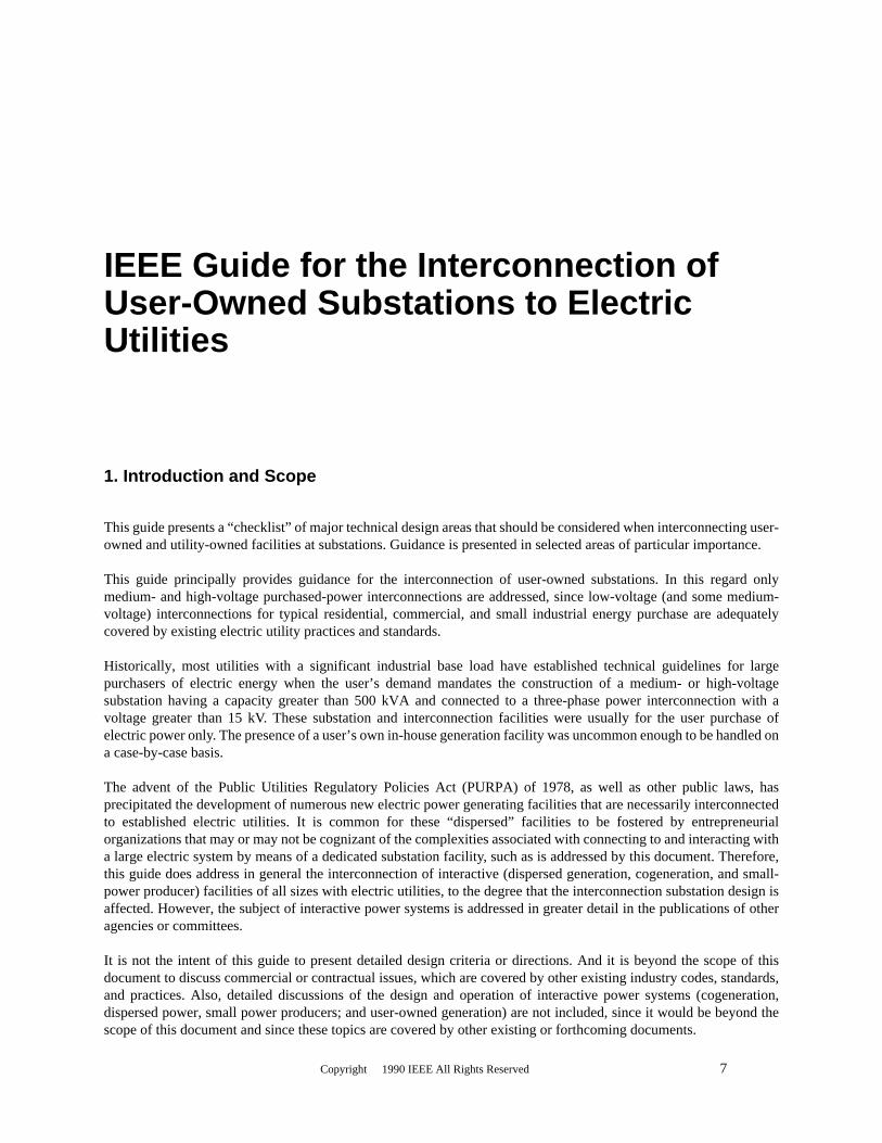
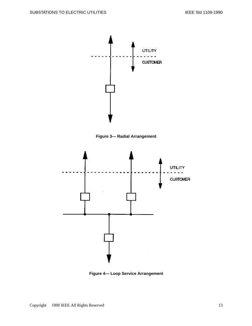
The simplest breaker arrangement is a single-series breaker in a simple radial arrangement (see Fig 3). However, anyscheme requiring more than one connection element each (i.e., line or load) for the utility or customer, or requiringloop service, will necessitate a more complex breaker arrangement. Several of the most common alternatives are: loopservice (Fig 4), “H” tie (Fig 5), ring bus (Fig 6), main and transfer bus (Fig 7), breaker and one half (Fig 8), and doublebreaker, double bus (Fig 9).
Copyright 1990 IEEE All Rights Reserved 13
SUBSTATIONS TO ELECTRIC UTILITIES IEEE Std 1109-1990
Figure 3— Radial Arrangement
Figure 4— Loop Service Arrangement

14 Copyright 1990 IEEE All Rights Reserved
IEEE Std 1109-1990 IEEE GUIDE FOR THE INTERCONNECTION OF USER-OWNED
Figure 5— “H”-Tie Arrangement
Figure 6— Ring Bus Arrangement
Copyright 1990 IEEE All Rights Reserved 15
SUBSTATIONS TO ELECTRIC UTILITIES IEEE Std 1109-1990
Figure 7— Main and Transfer Bus Arrangement
Figure 8— Breaker and One-Half Arrangement

16 Copyright 1990 IEEE All Rights Reserved
IEEE Std 1109-1990 IEEE GUIDE FOR THE INTERCONNECTION OF USER-OWNED
Figure 9— Double-Breaker, Double-Bus Arrangement
The final selection of one particular breaker arrangement (or a hybrid arrangement) depends on an engineeringanalysis of reliability and cost, both of which are functions of the number of breakers per line and the number of loador generation source(s). The arrangement should be acceptable to both the user and the utility.
Utilities may recommend a scheme that has been demonstrated by past performance to be appropriate for their servicearea. Figs 4, 5, 6, and 7 would include most typical user-owned installations. Fuses and circuit interrupters cansometimes be used in lieu of circuit breakers for protection and switching of circuits. These devices are usually usedonly for low-voltage or lower-medium-voltage (i.e., 15 kV voltage class or less) applications. Further, user-ownedgeneration may include its own dedicated generator breaker. Relaying of the generator breaker should be coordinatedwith the substation protective relaying.
4.2 Power Transformer Connections
Both user and utility should agree on the connection scheme for power and metering (instrument) transformers (wye-delta, delta-wye, wye-wye, zig-zig, autotransformer, etc.), as well as transformer capacity and voltage ratings. Theselection (or absence) of wye-connected system grounding sources can have significant implications on reliability,protective relay selection, metering, fault levels, over-voltage conditions, and equipment cost.

Copyright 1990 IEEE All Rights Reserved 17
SUBSTATIONS TO ELECTRIC UTILITIES IEEE Std 1109-1990
In typical present-day practice, high-voltage utility connections are solidly wye-grounded; plant medium-voltagesystems are resistance wye-grounded; and low-voltage systems are also solidly wye-grounded. There are exceptions toall of these.
When choosing transformer connections, the phase shifts should be considered to ensure proper synchronization ofany interactive power systems. Transformer design selection will require analysis of the utility system and localgenerator characteristics (see Section 5.).
4.3 Switch and Bus Construction
Substation switch and bus facilities can be open-air insulated, or metal-enclosed SF6 (sulfur hexafluoride) gas-insulated, or another type of construction. The conventional outdoor air-insulated substation normally uses aluminumcable or tubing for bus conductors because of economic advantages. (See IEEE Std 605-1987 [9].) Copper issometimes encountered in older stations or where corrosive environmental conditions preclude the use of aluminum.Energized parts are supported by porcelain, glass, polymer, or epoxy insulators and are maintained at safe vertical andhorizontal clearances, which are dictated by industry or utility standards and code requirements, such as ANSIC2-1990 [1] and IEEE Std 1119-1988 [14]. Compact SF6 gas-insulated substations (GIS) are generally installed wherespace is at a premium or contamination is a factor. All energized parts are concentrically placed in metallic enclosuresthat are at ground potential. The spaces between the live parts and the enclosures are filled with SF6 gas at anappropriate pressure to achieve the desired dielectric strength. See IEEE Std C37.122-1983 [5] for further informationon GIS.
Supporting structures for electrical equipment are most commonly constructed of galvanized steel. Other materialsthat can be used are aluminum, concrete pedestals, weathered steel, metalized steel, painted steel, and wood.
Metalclad switchgear is typically used for medium-voltage outdoor distribution substation facilities operating at 15 kVor less and occasionally for voltages greater than 15 kV, up to 38 kV.
Particular attention should be paid to access and removal of equipment, particularly transformers. Also, transformersmay require consideration of sound attenuation, oil-fire prevention, and oil-spill mitigation measures, particularly inresidential or wetland areas. IEEE Std 979-1984 [10] and IEEE Std 980-1987 [11] provide further guidance on fireprevention and oil-spill containment, respectively.
4.4 Interconnecting Lines Location and Orientation
The location and orientation of the substation facility should consider the direction and ultimate destination of theoverhead or underground transmission lines connecting to either the utility or the user’s facilities.
Provision should be made for appropriate right-of-way widths, avoidance of structures and other existing facilities,turning-tower positioning, and conductor-phase transpositions. The use of underground power cables is a technicallyfeasible but usually more expensive alternative to overhead lines, particularly for voltages above 38 kV.
4.5 Control Building
A substation usually includes a building or enclosed area to provide a clean, dry indoor environment for neededrelaying, metering, control, and communication equipment.
4.6 Future Expansion Consideration
Provision should be included in any substation for future expansion as needed to accommodate additional utilityinterconnections, additional user interconnections or loads, and additional breaker or switching complexity.

18 Copyright 1990 IEEE All Rights Reserved
IEEE Std 1109-1990 IEEE GUIDE FOR THE INTERCONNECTION OF USER-OWNED
5. Interactive Power (User-Owned Generation) Considerations
The presence of user-owned generating facilities operating in parallel with a large electric utility entails operationalcomplexities that would not exist in the case of a purchase-power-only user, as follows and as is further discussed inIEEE Std 1001-1988 [13].
5.1 Synchronizing
A proper synchronizing scheme consisting of necessary relays, indicators, control facilities, and a properly ratedpower circuit breaker should be provided for each generator to be connected to an interactive power system.
The synchronizing breaker(s) can be located in a user substation facility or in the power generating facility, dependingon specific site conditions, load current magnitude, electrical system configuration, and equipment cost. Thesynchronizing breaker should be relatively close to the generator it serves, since there is a voltage drop limit for direct(hard-wired) equipment control circuits. (See Section 9. for a discussion of control and communications options).
5.2 Startup/Auxiliary Power
Any generating facility should provide for its normal plant (or station) auxiliary power requirements. These loads canbe supplied from the user’s own load buses or from the substation facility. If the generator is a unit-connectedarrangement (i.e., normal auxiliary loads provided from the generator bus), an additional power source is needed tosupply the auxiliary loads when the generator is off-line or not synchronized. Further, an appropriate transfer schemeshould be provided to permit the transfer of auxiliary load from startup to normal source and vice versa.
The phase relationship of these two sources must be coordinated, especially if they originate at different voltage levelsor if they include different voltage transformation sequences. Voltage regulation will be a consideration, since thegenerator(s) could be supporting the system voltage during operation or the generator auxiliary loads could be actingas a major load during the startup mode.
5.3 Generator Grounding
The grounding of a generator should be fully evaluated with regard to its impact on the following:
1) The maximum fault-current level to which the generator will be subjected2) The presence of sufficient ground fault current to permit detection and selective isolation of the faulted
generator without subjecting other generators to unnecessary additional ground fault current3) The grounding of the balance of the auxiliary power distribution system or utility system when the generator
is disconnected
(2) is of particular importance when multiple generators are connected to a common bus. The ideal grounding schemefor a larger generator provides for the generator neutral to be grounded through a distribution transformer with asecondary winding resistor. However, this assumes that a wye-delta (or delta-wye) step-up transformer is provided foreach generator power interconnection, which may not always be the case. For multiple generators connected to asingle bus, resistance grounding is typically used. Effective ground protection of the faulted generator can be providedwith low resistance grounding. However, resistance grounding usually subjects equipment to higher fault levels thandistribution transformer grounding.

Copyright 1990 IEEE All Rights Reserved 19
SUBSTATIONS TO ELECTRIC UTILITIES IEEE Std 1109-1990
5.4 Generator Characteristics
While it is understood that the gross output capability of the generator(s) is probably the most important rating ofinterest to the owner, as well as to the utility, the specific generator electrical and dynamic characteristics will also beof equal importance to both parties and should not be overlooked.
The generator owner will need to obtain specific generator electrical characteristics in order to design the plantelectrical distribution system. Furthermore, the utility will usually require significant dynamic data as well, in order toascertain the generator’s overall impact on system fault levels and stability. The latter is particularly true for a largesynchronous generator.
Harmonic voltage generation between reactive components within an operating system can cause severe damage toequipment. The design effort should address the matter as a potential problem.
Any generator connected to an operating electrical system becomes, during its synchronous operation, functionally apart of that system.
5.5 Reactive Capability
As a corollary to the usual understanding that a large power user is expected to maintain the facility reactive powerdemands (power factor) within certain agreed limits, a utility may require each generator to be capable of providingreactive power to the utility system in proportion to the unit size and capability and within specified voltage limits forboth generator(s) and system. This is a point that should be established early, since the reactive power contributionfrom a facility, whether expressed as a gross power factor at the generator, a net power factor at the utility, or a desiredvoltage to be maintained at the utility bus, may ultimately be reflected in changes in the capability of the generator(rotor, stator, or excitation system) or in the increased heating of these components.
Additional reactive capability does not entail any additional turbine (power) capability, but is reflected in generatorand excitation system thermal capacity.
If a generator (or generators) is not capable of meeting some reactive power (var) requirement, shunt capacitors’ orstatic var compensators or both may be required to supplement the generator contribution. The location of shuntcapacitors on the utility or user system should be reviewed to avoid self-excitation of the generator-capacitor networkin the event of sectionalization and isolation (“islanding”) of the interactive systems. If capacitors are present,switching devices that are transfer-tripped by the utility may be necessary. This particularly applies to inductiongenerators. Any application of capacitors should be done with a full understanding of capacitor effects.
A fundamental premise is that the utility is responsible for providing reliable service in accordance with applicableregulatory requirements that should not be compromised by user-owned operations. Conversely, user-ownedgeneration should not be subject to extraordinary requirements.
5.6 Isolating Switch
The user and utility should agree on the necessity of providing a manually operated isolation switch(es) with a visiblebreak to isolate the generator(s) from the interconnection. Switch location, accessibility, and capability of being lockedor tagged open should also be established.

20 Copyright 1990 IEEE All Rights Reserved
IEEE Std 1109-1990 IEEE GUIDE FOR THE INTERCONNECTION OF USER-OWNED
6. Substation Facilities Design
The prudent design of a user-owned substation should include the following significant areas for consideration in thedesign criteria.
6.1 Grounding
A buried grounding grid of bare cable, possibly including electrodes (ground rods), is necessary for personnel safetyand to provide ground connecting points for equipment. Normally, the substation grounding grid design shouldconform to the requirements of IEEE Std 80-1986 [6]. A ground-resistance test should be required and conducted inaccordance with IEEE Std 81-1983 [7]. The grounding design criteria should be coordinated with adjacent utilities,plants, or other facilities to ensure that transfer potentials will not present personnel hazards in areas remote from anelectrical event or will not damage communications circuits between the user-owned facilities and any remotefacilities.
The effect of a generation facility or substation grounding system on adjacent existing or future cathodic protectionsystems (e.g., pipelines) needs careful study and, probably, field testing.
6.2 Insulation Levels (BIL)
For any given electric power interconnection, the basic impulse insulation level (BIL) (or switching insulation level[SIL] for EHV voltage levels) should be coordinated for power distribution and transmission lines and equipment.Industry references or the local utility are the appropriate sources for existing insulation levels, which are frequentlydifferent for overhead line, insulated cable, and transformer insulation systems at the same voltage level in the sameregion.
6.3 Clearances and Access
Appropriate normal and minimal electrical clearances from energized parts above walkways, roads, and railroads andin other special circumstances are specified in ANSI C2-1990 [1] and IEEE Std 1119-1988 [14], local utilityrequirements, and state and local codes and ordinances. Overhead high-voltage lines can require significant right-of-way area. The presence of energized overhead conductors can affect some potential uses of property located under oradjacent to the conductors. The local utility should be consulted to provide access requirements for maintenance,operation, and metering facilities.
6.4 Lighting
Appropriate minimum lighting levels for various circumstances of indoor, outdoor, and roadway areas are given inNFPA 70-1990 [16] and ANSI C2-1990 [1], in ANSI and IES standards, and in other industry sources. Emergencylighting should be provided in attended areas, in accordance with local codes and regulations.
6.5 Lightning (Surge) Protection
Lightning (surge) protection for substation facilities should be designed for the isokeraunic level (thunderstorm daysper year) for the particular site location. The local utility may be the best source of information on local lightningfrequency, outage records, and application of particular lightning protection methods (shield wires, masts, arrays,arresters, higher BIL levels, reclosing, etc.) to the local system. See IEEE P998 [12] for further background on directstroke lightning protection. For high-voltage facilities, switching surges are an additional design consideration. Theneed for surge protection at generator, transformer, and cable terminals should be considered.
Copyright 1990 IEEE All Rights Reserved 21
SUBSTATIONS TO ELECTRIC UTILITIES IEEE Std 1109-1990
6.6 Transmission (or Distribution) Line Termination
High-voltage transmission lines or medium-voltage distribution lines, whether overhead or underground cable, willusually constitute the most significant physical interface between a user-owned substation and the electric utility.Because of this, particular attention is needed to coordinate the interfacing span between the last utility tower and thesubstation terminal structure for overhead lines. For underground lines, the presence of existing underground utilitiesin the substation vicinity should be identified, which may impact a new underground cable location or rating. For bothoverhead and underground lines, orientation of the substation in relation to the utility and the user’s lines should bearranged to minimize line angles, turning towers, crossings, etc., all of which will impact on the complexity and costof the interconnection transmission facilities.
6.7 Switching Equipment
The final selection and arrangement of particular substation switching devices is closely related to the substationarrangement, discussed in Section 4.
For interactive interconnections, either power circuit breakers or circuit interrupters are required for power circuitswitching and fault interruption. The choice between these switching devices will depend on required faultinterruption capability, clearing and reclosing requirements, etc. For purchase-power-only interconnections, theswitching equipment may be power circuit breakers, circuit interrupters, or fuses. The choice between these switchingdevices will depend on required fault interruption capability and on clearing and reclosing requirements. In addition,the application of fuses should address reduced reliability, increased outage time, single-phasing, ferroresonance, etc.
Disconnect switches are capable of interrupting line charging currents for short lines and switching low-leveltransformer magnetizing currents, particularly when arcing horns or quick-break (high-speed) interrupting devices areadded to the switch. However, they are normally used only to isolate power switching apparatus, lines, and buses andare not suitable for application as a principal switching device.
Any further discussion of the numerous varieties and applications of switching devices mentioned above is beyond thescope of this guide.
6.8 Instrument Transformers
Instrument transformers are devices that are needed to produce a low-voltage reference potential or current source asrequired for protective relaying, synchronizing, metering, control, and indication functions.
Potential sources can be oil-filled or dry-type (epoxy or rubber insulated) wound voltage transformers, capacitorvoltage transformers (CVTs), coupling capacitor potential devices, (CCPDs) or bushing potential devices. Voltagetransformers are the most accurate sources of potential and are usually needed for revenue metering. Bushing potentialdevices, transformer or breaker mounted, are usually suitable only for indicating the presence of voltage and areinadequate for critical relaying or metering functions.
Current sources can be separately mounted oil-filled or dry-type (epoxy or rubber insulated) current transformers orbushing current transformers (BCTs). Again, separately mounted current transformers are the most accurate and areusually needed for revenue metering. Bushing current transformers, both transformer- and breaker-mounted, aresuitable for the majority of relaying, control, indication, and nonrevenue metering functions.
6.9 Cable Systems
Cable systems required to interconnect protective relaying, metering, instrumentation, control, communications, andlow-voltage power equipment systems should be in conformance with IEEE Std 525-1987 [8] or local utility practice.
22 Copyright 1990 IEEE All Rights Reserved
IEEE Std 1109-1990 IEEE GUIDE FOR THE INTERCONNECTION OF USER-OWNED
7. Protective Relaying
Protective relaying is necessary to detect system disturbances and to initiate proper response from power switchingequipment. Protective relaying also is necessary to monitor synchronizing, load transfers, and out-of-step operatingconditions.
Protective relay application is probably the most complex aspect of power systems design. Successful design andoperation needs intimate coordination of utility and owner protective relaying facilities and philosophies. Relay andother devices usually are designated as outlined in IEEE Std C37.2-1987 [4] or as specified by the local utility.
The following categories of protective relaying application are typical.
7.1 Line Protection
Line protection relays monitor the condition of a transmission line and initiate isolation of the line if a fault is detected.Lightning is frequently the principal source of transmission and distribution line faults. Trees, animals, and accidentsare other sources of faults.
7.2 Transformer Protection
Transformer protection relays monitor the condition of a power transformer and initiate its isolation in the eventabnormal conditions are detected that can indicate overloading or an internal fault.
7.3 Bus Protection
Bus protection relays monitor the integrity of a power bus to which several lines, generators, etc. are connected.Detection of a bus fault will initiate isolation of the bus from all connected elements.
7.4 Synchronizing/Synchronism Check
Synchronizing and synchronism check relays are necessary to verify the phase relationship of interactive powersystems or generators before permitting the interconnection of two energized (interactive) systems. An automaticsynchronizing device may be used to control the speed and voltage of a generator and initiate connection to the system.
7.5 Reclosing and Transfer Tripping
Reclosing relays are employed with power circuit breakers to permit the rapid restoration of service to a transmissionline that has been isolated due to the detection of a transient fault condition. Automatic reclosing is appropriate tosupport continuity of service and to maintain stability of the interconnected system. The concept of rapid reclosing isbased on the transient nature of most line faults, particularly those caused by lightning. Particular care should be usedin applying reclosing to generator interconnections. An automatic reclosing scheme should be approved by andcoordinated with the electric utility. Automatic reclosing is generally not applied to underground (cable) lines.Transfer-trip relaying is frequently employed to isolate a generator from a faulted line so as to prevent damage due toreclosing out of synchronism.
7.6 Load Shedding and “Islanding”
Load shedding is necessary when available generation in a defined system, such as a large industrial or cogenerationplant, should suddenly become insufficient to meet the connected load with the system. Such action would serve to

Copyright 1990 IEEE All Rights Reserved 23
SUBSTATIONS TO ELECTRIC UTILITIES IEEE Std 1109-1990
preserve essential loads in operation. Such a condition could be brought about by loss of in-plant generation or loss ofa user-utility interconnection tie line that is importing power at the time of failure. The decay of online generator(s)frequency can be measured to initiate the sequential removal of selected, low-priority plant loads with the ultimatepurpose of maintaining service to essential loads that in-plant generation is capable of supplying. The completeisolation of independent generating systems results in “islands” of load and generation, which are individually lessreliable and more sensitive to disturbance than the interconnected interactive system. This islanding condition alsoraises safety concerns and may necessitate transfer-tripping of additional switching devices to completely isolate thesystems. Reconnection of the isolated systems to a larger, stable system can also be difficult.
7.7 Generator Protection
Specifically designed relaying is required to monitor the condition of the numerous mechanical and electricalfunctions of a turbine generator or any other type of generating machine. Because of the significant capital investmentinherent in any generating unit, sensitivity and speed of response are necessary to detect abnormal conditions. Thispermits isolating and repair before a catastrophic failure can occur, with its consequent financial and safetyimplications.
7.8 Relaying Interfaces and Interlocks
Protective relaying systems can be interconnected with other electrical control and metering systems and may beinterconnected with mechanical process systems. Interlocks establish permissive or restrained systems of operationthat are necessary to ensure the safety of operation and the protection of the investment.
8. Metering and Instrumentation
The following types of metering could be expected to be provided as part of any user-owned facility interconnected toan electric utility.
8.1 Revenue Metering
This is a very significant interconnection parameter for user-purchased power and for sale of user-generated electricenergy. The revenue parameter(s) to be metered will depend on the specific interconnection agreement and couldinclude kWh, kvarh, kW, kvar, kVA, and power factor, in almost any combination. Since bidirectional real and reactivepower flow may be possible, detented (in and out) metering is frequently necessary. Also, time-of-day pricing may beincluded in the specific rate structure, tariff, or contract.
Revenue metering requires the most accurate metering equipment available. This includes calibrated and certifiedmetering accuracy current and voltage transformers, transducers, recording devices, and instruments. Most utilitiesusually have well-defined requirements for the configuration, type, and location of revenue metering equipment.Revenue metering is normally located in areas that are accessible to the utility representatives, although it is notunreasonable to request a cumulative reading to be duplicated at a user-maintained area in order to be monitored by thecustomer or owner. A communications line is needed if remote access of the metering data is necessary (i.e., fordispatching or load research).
8.2 Indicating Instruments and Status
Indicating instruments are provided to display the presence and magnitude of parameters on specific lines, buses, andequipment. Parameters that could be expected to be measured are voltage, current, kW, kvar, kWh, power factor, kVA,

24 Copyright 1990 IEEE All Rights Reserved
IEEE Std 1109-1990 IEEE GUIDE FOR THE INTERCONNECTION OF USER-OWNED
and kvarh. The normal location for such an indication would be at a substation control house, generator control room,or other accessible area.
The choice of indicating instruments is very site-, user-, and utility-specific in that instruments are used to supportoperations and maintenance functions. Indicating instruments as implied here would be located in the geographicvicinity of the user-owned facility. Indicating instruments also include the discrete (open-closed-trip) status display ofequipment such as power circuit breakers, electrically-operated load interrupters, and disconnecting switches.
8.3 Telemetering
Telemetering is the transmission of analog or digital parameters to a remote location. Telemetering is closelyassociated with supervisory control, which is discussed further in 9.2. The parameters that can be telemetered to aremote location are the same as those for local metering, status, and indication.
The remote location that would likely be the destination for telemetered data would be a utility dispatch center or auser’s remote control/monitoring facility. Telemetering of data can be accomplished over wire circuits for shortdistances. For long-distance telemetering, dedicated communications lines, carrier equipment, radio transmission,microwave facilities, or fiber optics circuitry is needed.
9. Control and Communications
Control facilities are needed to provide the human interface for the operation of installed equipment. Communicationsmedia of various types are used to permit the transmission and reception of control initiation signals, as well as for datatransmission (see 8.3). Utility companies may need remote metering, monitoring, and control capabilities of large,dispersed user-owned generating facilities in order to satisfy overall system safety and operation needs.
9.1 Local Control
Local control is usually accomplished by a direct electrical, mechanical, pneumatic, or hydraulic device and is initiatedimmediately at the equipment or at some control facility within sight or walking distance of the equipment. It is theleast sophisticated (and most reliable) control mode.
“Remote Control” is an extension of local control, which implies a greater distance between the controlled device andthe initiating signal, but this control can utilize the same communication medium as for local control and, in fact, candiffer only by degree of proximity to the controlled device. Remote control is particularly applicable to unattendedlocations, which is the usual case for substations, switchyards, or switching stations.
9.2 Supervisory Control
Supervisory control, also generically referred to as SCADA (Supervisory Control and Data Acquisition) systems,represents the long-distance control and data transmission methodology for distances much greater than that capablewith direct local or remote control. As opposed to hard-wired direct local or remote control, which utilizes a dedicatedwire pair or similar dedicated communication medium for each control or data signal, supervisory control usuallyutilizes multiplex technology to superimpose multiple signals on a single communication channel. This system uses anRTU (Remote Terminal Unit) at each terminal to collect, process, and transmit the appropriate multiple input andoutput signals. Supervisory control is generally needed for a utility interconnection that includes remote utility controlof selected customer-owned equipment, such as high-voltage power circuit breakers. Additional information is givenin IEEE Std C37.1-1987 [3].
Copyright 1990 IEEE All Rights Reserved 25
SUBSTATIONS TO ELECTRIC UTILITIES IEEE Std 1109-1990
9.3 Remote Dispatch
Remote dispatch is merely local control of equipment in accordance with the verbal instructions received from aremote central control location, such as a utility central power dispatch center. Remote dispatch can reasonably beexpected to be considered as part of the operations functions of any generator connected to an operating utility system.A voice communication channel, either dial-up or dedicated, is the normal dispatch coordination medium.
9.4 Communications
Various communications media may be considered for the different control functions, as follows.
1) Metallic Hardwire—Suitable only for relatively short distances (up to several hundred feet) for control/relaying/metering functions.
2) Telephone—For voice, SCADA and selected relaying functions (not guaranteed for continuous integrity if anormal line).
3) Power Line Carrier—For voice or SCADA functions (also suitable for relaying functions). Maintainingcontinuous integrity during line faults can be a problem.
4) Leased Telephone Channel—For voice or SCADA functions (also for relaying functions). May be morereliable than a normal telephone line).
5) Microwave—For voice, SCADA, and relaying functions (expensive except for handling many signals at greatdistances; political and environmental considerations may also be necessary).
6) Fiber Optics—For voice, SCADA, and relaying functions (option to a leased telephone line).7) Radio—For voice communications (backup to other systems and for limited switching operations).
Redundant communications links should be considered for any essential function or for installations with significantcustomer-owned generation. Reliable voice communication is essential between generator operators and the utility,particularly during system emergencies.
9.5 Communication Circuit Protection
The reliability of the communication circuit should be considered to ensure the integrity of the circuit under adverseconditions or to minimize the likelihood of circuit interruption. Communication circuits should be supervisedcontinuously and checked periodically to ensure their continued integrity.
Events that could cause circuit interruption can be: digging of buried cables, lightning, insulation failure of conductorsor devices due to transient potential rise, circulating currents, vandalism, and equipment maintenance.
10. Maintenance and Operation
In addition to the design coordination necessary to realize the physical and electrical interfaces between the user’sfacilities and the utility, it is necessary to coordinate normal life-of-plant maintenance and operation functions. Thedetails of such coordination are usually outlined in an operational agreement to which all parties are obligated.Particular items that are likely to be covered by an operational agreement are as follows.
10.1 Coordination of Switching
For personnel safety and in order to avoid disruption of user and utility service or equipment damage or both.

26 Copyright 1990 IEEE All Rights Reserved
IEEE Std 1109-1990 IEEE GUIDE FOR THE INTERCONNECTION OF USER-OWNED
10.2 Tagging, Lockout, and Grounding
Clearly defined procedures for isolating and grounding of equipment and circuits as needed for utility, user, andcontractor maintenance functions.
10.3 Personnel Safety and Training
Minimum level of training needed for operations, maintenance, and construction personnel.
10.4 Access
Provision for both user and utility ingress and egress in all weather conditions at any time of day.
10.5 Testing
From time to time, customer or utility equipment may have to be removed from service. Such equipment may havefailed, may have to be maintained, or may have to be tested. Circuit breakers require periodic preventive maintenance.Oil-filled devices are often DobleTM tested for their power factor or dissipation factor. Instrument transformers usedfor metering may have to be tested for accuracy. Therefore, current transformers may have to have bypasses anddisconnects installed.
The station owner should be aware of these temporary and scheduled equipment outages and should factor them intothe planned operation of the station and the generator(s).
10.6 Emergency Conditions
The user and utility should agree on any special control requirements for the generating facility during periods ofdefined utility system emergency condition operation. Administrative instructions should be made available to theuser’s operating personnel.
11. Administrative Items
The following administrative items, among others, should be considered for equipment and facilities that interfacewith both the user and utility facilities.
1) Drawings and Data—A schedule should be prepared for submission and review of appropriate drawings anddata by all parties during the user-facility interconnection design phase and utility or user systemmodification activities.
2) Color Codes—For cable, wiring, raceway, signs, etc.3) Nameplates—For major equipment.4) Equipment Numbers—For operations and maintenance coordination.5) Signs—To indicate ownership limits and for safety.6) Local Building Codes Compliance7) Access of Utility Employees to the User’s Substation8) Insurance and Liability

Copyright 1990 IEEE All Rights Reserved 27
SUBSTATIONS TO ELECTRIC UTILITIES IEEE Std 1109-1990
12. Contractual Documents
This guide is only a basis for specific discussions and agreements. It is understood that specific user-utility financial,operating, design, and other issues would be outlined in formal contracts, operating agreements, and other documents.

28 Copyright 1990 IEEE All Rights Reserved
IEEE Std 1109-1990 IEEE GUIDE FOR THE INTERCONNECTION OF USER-OWNED
Annex
(Informative)
(This Appendix is not a part of IEEE Std 1109-1990, IEEE Guide for the Interconnection of User-Owned Substations to ElectricUtilities, but is included for information only.)
Related Code and Standard Agencies (and area of applicability)
American Concrete Institute (ACI)P.O. Box 19150, Redford StationDetroit, MI 48219Concrete Design
Association of Edison IlluminatingCompanies (AEIC)51 East 42nd StreetNew York, NY 10017HV Cable Systems
American Institute of Steel Construction (AISC)Three Gateway Center Suite 2350Pittsburgh, PA 15222Steel Application
American National Standards Institute (ANSI)1430 BroadwayNew York, NY 10018Application and Design Standards
American Society of Mechanical Engineers (ASME)345 East 47th StreetNew York, NY 10017Mechanical Equipment
American Society of Testing and Materials (ASTM)1916 Race StreetPhiladelphia, PA 19103Components

Copyright 1990 IEEE All Rights Reserved 29
SUBSTATIONS TO ELECTRIC UTILITIES IEEE Std 1109-1990
Building Officials and Code Administrators International (BOCA)4051 W. Flossmoor RoadCountry Club Hills, IL 60477Building Codes
Electrical Apparatus Service Association (EASA)1331 Baur BoulevardSt. Louis, MO 63132Electrical Testing and Maintenance
Edison Electric Institute (EEI)1111 19th Street, N.W.Washington, D.C. 20036Handbook for Electricity Metering
Factory Mutual System Engineering and Research Association (FMERO)1151 Boston-Providence TurnpikeNorwood, MA 02062Insurance Requirements
Insulated Cable Engineers Association (ICEA)P.O. Box PSouth Yarmouth, MA 02664Cable Application
Institute of Electrical and Electronics Engineers (IEEE)445 Hoes LanePiscataway, NJ 08855Electrical Systems and Equipment Application, National Electrical Safety Code
Illuminating Engineering Society of North American (IESNA)345 East 47th StreetNew York, NY 10017Lighting

30 Copyright 1990 IEEE All Rights Reserved
IEEE Std 1109-1990
Instrument Society of America (ISA)67 Alexander DriveP.O. Box 12277Research Triangle Park, NC 27709Instruments
National Electrical Manufacturers Association (NEMA)2102 L Street, N.W.Washington, D.C. 20037Electrical Equipment Design
National Fire Protection Association (NFPA)Batterymarch ParkQuincy, MA 02269Fire Protection Requirements, National Electrical Code
Prestressed Concrete Institute (PCI)201 North Wells StreetChicago, IL 60606Concrete Structures
Southern Building Code Congress, International (SBCCI)900 Montclair RoadBirmingham, AL 35213Building Codes
Steel Structures Painting Council (SSPC)4400 Fifth AvenuePittsburgh, PA 15213Surface Protection and Coatings