Embed Size (px)
Citation preview
8/6/2019 Iee Sample - Copy
http://slidepdf.com/reader/full/iee-sample-copy 1/4
VTU/Visai/Elect-08
Abstract — Air conditioner has a outdoor unit which has a fanrotating at high speed. It is used to blow out the hot air frominside of room to outside . Besides this the kinetic energy of fanis not fully utilized. this project makes use this kinetic energyto generate electricity.It is a innovative idea. The energygenerated can be fed back to AC to reduce its powerconsumption or can be utilized for other purpose. It can be evenattached to a existing unit. The design and cost of implementing it is very less.
Index Terms :1) Faradays Laws2) Coupling Rods3) Induced EMF 4) Generator Efficiency
II.INTRODUCTION
We all have been using AC without knowing the amount of power that is wasted unutilized in it. this project finds out aneffective way of harnessing this energy. If this idea isrealized efficiently, it could generate unbelievable amount of
power. on the whole. it has the potential to be simple yethighly effective innovation. It could also help to satisfy thegrowing energy demands and helps us create a more‘smarter and energy efficient planet
III. PRINCIPLE OF OPERATION
” When a permanent magnet is moved relative to aconductor, or vice versa, an electromotive force is created”.
Faraday's law of induction makes use of the magnetic fluxΦ B through a surface Σ, defined by an integral over a surface :
where d A is an element of surface area of the moving surfaceΣ(t ), B is the magnetic field, and B·d A is a vector dot
product . The surface is considered to have a "mouth"outlined by a closed curve denoted ∂Σ( t ). When the fluxchanges, Faraday's law of induction says that the work done (per unit charge) moving a test charge around theclosed curve ∂Σ( t ), called the electromotive force (EMF), isgiven by:
where is the magnitude of the electromotive force (EMF)in volts and Φ B is the magnetic flux in webers . The directionof the electromotive force is given by Lenz's law.
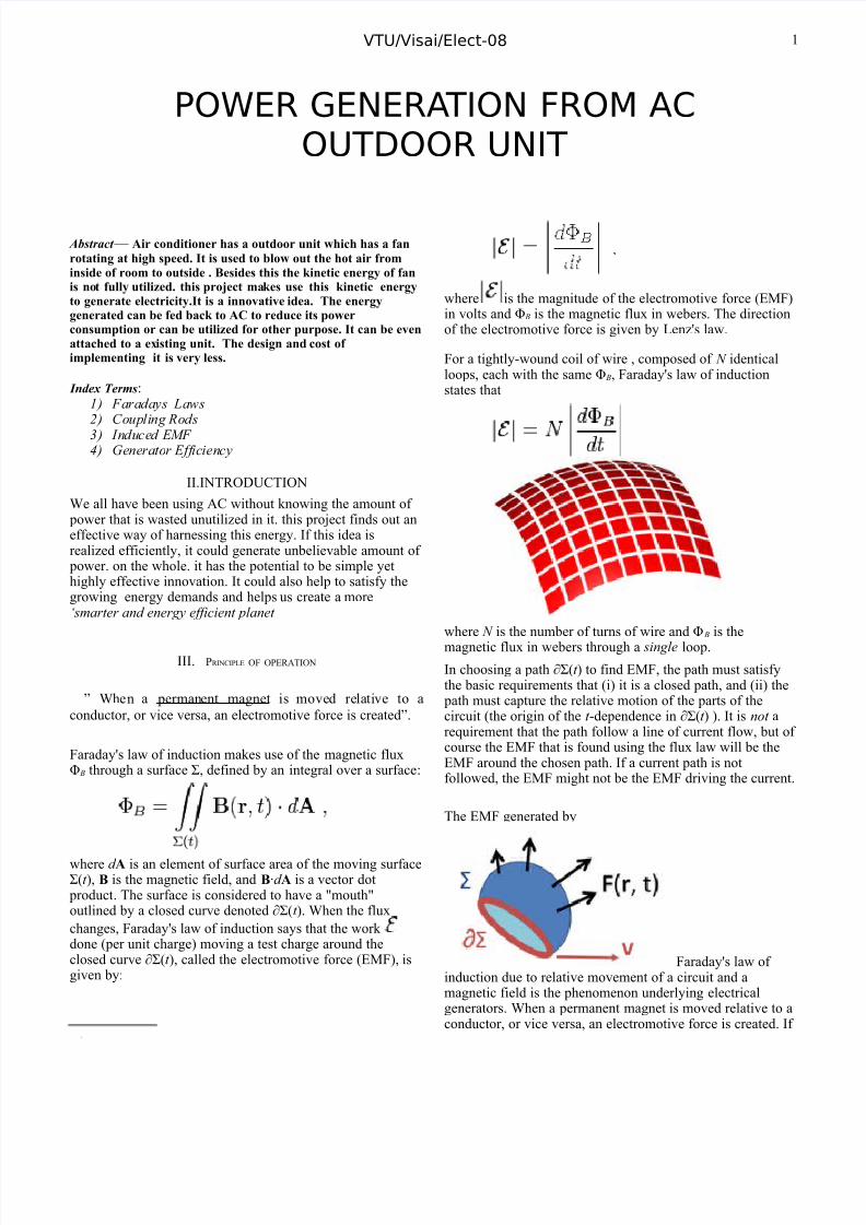
For a tightly-wound coil of wire , composed of N identicalloops, each with the same Φ B, Faraday's law of inductionstates that
where N is the number of turns of wire and Φ B is themagnetic flux in webers through a single loop.In choosing a path ∂Σ( t ) to find EMF, the path must satisfythe basic requirements that (i) it is a closed path, and (ii) the
path must capture the relative motion of the parts of thecircuit (the origin of the t -dependence in ∂Σ( t ) ). It is not arequirement that the path follow a line of current flow, but of course the EMF that is found using the flux law will be theEMF around the chosen path. If a current path is notfollowed, the EMF might not be the EMF driving the current.
The EMF generated by
Faraday's law of induction due to relative movement of a circuit and amagnetic field is the phenomenon underlying electricalgenerators. When a permanent magnet is moved relative to aconductor, or vice versa, an electromotive force is created. If
POWER GENERATION FROM ACOUTDOOR UNIT
1
8/6/2019 Iee Sample - Copy
http://slidepdf.com/reader/full/iee-sample-copy 2/4
VTU/Visai/Elect-08
the wire is connected through an electrical load , current willflow, and thus electrical energy is generated, converting themechanical energy of motion to electrical energy. For example, the drum generator . In the Faraday's disc example,the disc is rotated in a uniform magnetic field perpendicular to the disc, causing a current to flow in the radial arm due tothe Lorentz force. It is interesting to understand how it arisesthat mechanical work is necessary to drive this current. Whenthe generated current flows through the conducting rim, amagnetic field is generated by this current through Ampere'scircuital law . The rim thus becomes an electromagnet thatresists rotation of the disc (an example of Lenz's law ). On thefar side of the figure, the return current flows from therotating arm through the far side of the rim to the bottom
brush. The B-field induced by this return current opposes theapplied B-field, tending to decrease the flux through that sideof the circuit, opposing the increase in flux due to rotation.On the near side of the figure, the return current flows fromthe rotating arm through the near side of the rim to the
bottom brush. The induced B-field increases the flux on thisside of the circuit, opposing the decrease in flux due torotation. Thus, both sides of the circuit generate an emf opposing the rotation. The energy required to keep the discmoving, despite this reactive force, is exactly equal to theelectrical energy generated (plus energy wasted due tofriction , Joule heating , and other inefficiencies). This
behavior is common to all generators converting mechanicalenergy to electrical energy.
Although Faraday's law always describes the working of electrical generators, the detailed mechanism can differ indifferent cases. When the magnet is rotated around astationary conductor, the changing magnetic field creates anelectric field, as described by the Maxwell-Faraday equation,and that electric field pushes the charges through the wire.This case is called an induced EMF. On the other hand, whenthe magnet is stationary and the conductor is rotated, themoving charges experience a magnetic force (as described bythe Lorentz force law), and this magnetic force pushes thecharges through the wire. This case is called motional EMF.
Example: Spatially varying Magnetic field
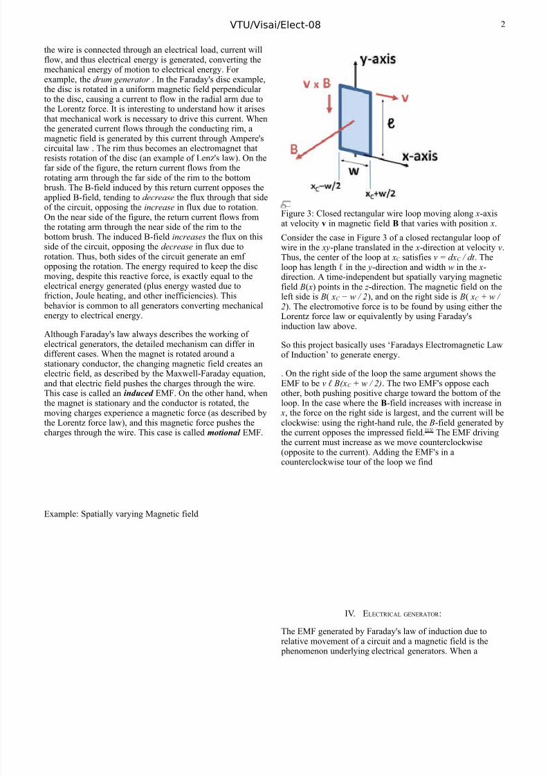
Figure 3: Closed rectangular wire loop moving along x-axisat velocity v in magnetic field B that varies with position x.
Consider the case in Figure 3 of a closed rectangular loop of wire in the xy-plane translated in the x-direction at velocity v.Thus, the center of the loop at xC satisfies v = dx C / dt . Theloop has length ℓ in the y-direction and width w in the x-direction. A time-independent but spatially varying magneticfield B( x) points in the z -direction. The magnetic field on theleft side is B( xC − w / 2 ), and on the right side is B( xC + w / 2). The electromotive force is to be found by using either theLorentz force law or equivalently by using Faraday'sinduction law above.
So this project basically uses ‘Faradays Electromagnetic Lawof Induction’ to generate energy.
. On the right side of the loop the same argument shows theEMF to be v ℓ B(xC + w / 2) . The two EMF's oppose eachother, both pushing positive charge toward the bottom of theloop. In the case where the B-field increases with increase in
x, the force on the right side is largest, and the current will beclockwise: using the right-hand rule, the B-field generated bythe current opposes the impressed field. [13] The EMF drivingthe current must increase as we move counterclockwise(opposite to the current). Adding the EMF's in acounterclockwise tour of the loop we find
IV. E LECTRICAL GENERATOR :
The EMF generated by Faraday's law of induction due torelative movement of a circuit and a magnetic field is the
phenomenon underlying electrical generators. When a
2
8/6/2019 Iee Sample - Copy
http://slidepdf.com/reader/full/iee-sample-copy 3/4
VTU/Visai/Elect-08
permanent magnet is moved relative to a conductor, or viceversa, an
V. C OMPONENTS OF THE PROJECT :
1)Electrical Generator:The EMF generated by Faraday's law of induction due torelative movement of a circuit and a magnetic field is the
phenomenon underlying electrical generators . When a permanent magnet is moved relative to a conductor, or viceversa, an electromotive force is created. If the wire isconnected through an electrical load , current will flow, andthus electrical energy is generated, converting the mechanicalenergy of motion to electrical energy. A differentimplementation of this idea is the Faraday's disc, shown insimplified form in Figure. Note that either the analysis of Figure , or direct application of the Lorentz force law, showsthat a solid conducting disc works the same way.
In the Faraday's disc example, the disc is rotated in a uniformmagnetic field perpendicular to the disc, causing a current toflow in the radial arm due to the Lorentz force. It isinteresting to understand how it arises that mechanical work
is necessary to drive this current. When the generated currentflows through the conducting rim, a magnetic field isgenerated by this current through Ampere's circuital law(labeled "induced B" in Figure 8). The rim thus becomes anelectromagnet that resists rotation of the disc (an example of Lenz's law ). On the far side of the figure, the return currentflows from the rotating arm through the far side of the rim tothe bottom brush. The B-field induced by this return currentopposes the applied B-field, tending to decrease the fluxthrough that side of the circuit, opposing the increase in fluxdue to rotation. On the near side of the figure, the returncurrent flows from the rotating arm through the near side of the rim to the bottom brush. The induced B-field increasesthe flux on this side of the circuit, opposing the decrease in
flux due to rotation. Thus, both sides of the circuit generatean emf opposing the rotation. The energy required to keepthe disc moving, despite this reactive force, is exactly equalto the electrical energy generated (plus energy wasted due tofriction , Joule heating , and other inefficiencies). This
behavior is common to all generators converting mechanicalenergy to electrical energy.
The generator plays the vital role in the project . it is the partwhere the kinetic energy of AC outdoor unit fan getsconverted to electrical energy.
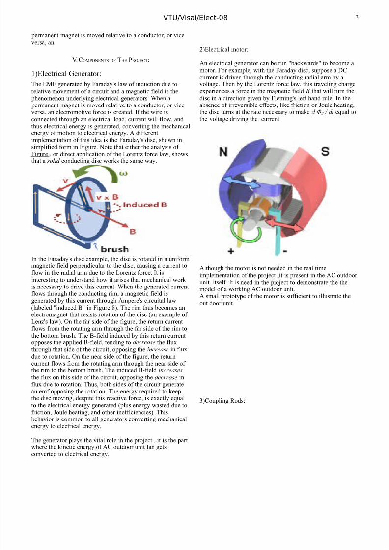
2)Electrical motor:
An electrical generator can be run "backwards" to become amotor. For example, with the Faraday disc, suppose a DCcurrent is driven through the conducting radial arm by avoltage. Then by the Lorentz force law, this traveling chargeexperiences a force in the magnetic field B that will turn thedisc in a direction given by Fleming's left hand rule. In theabsence of irreversible effects, like friction or Joule heating ,the disc turns at the rate necessary to make d Φ B / dt equal tothe voltage driving the current
Although the motor is not needed in the real timeimplementation of the project ,it is present in the AC outdoor unit itself .It is need in the project to demonstrate the themodel of a working AC outdoor unit.A small prototype of the motor is sufficient to illustrate theout door unit.
3)Coupling Rods:
3
8/6/2019 Iee Sample - Copy
http://slidepdf.com/reader/full/iee-sample-copy 4/4
VTU/Visai/Elect-08
These rods are used to couple the rotation of the AC outdoor unit fan to the fan of the generator. It can be made of steel or some alloys for high tensile strength.It is made hollow toreduce the weight hence increasing the efficiency.
VI. W ORKING OF THE PROJECT :
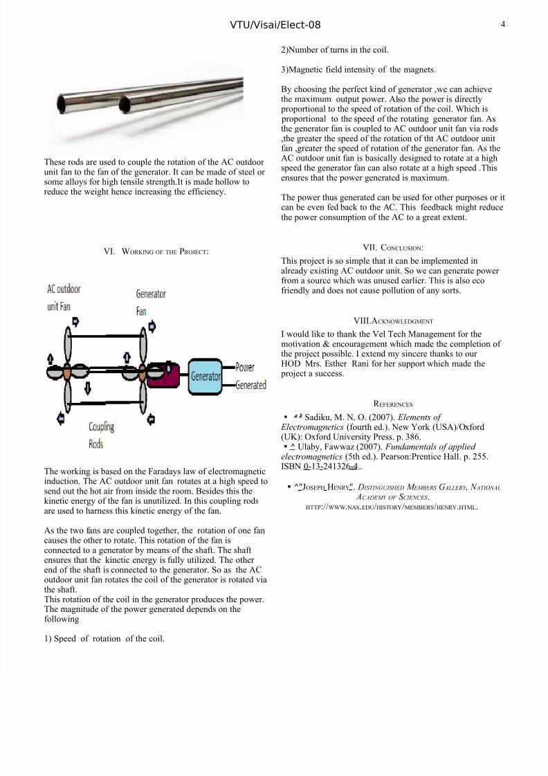
The working is based on the Faradays law of electromagneticinduction. The AC outdoor unit fan rotates at a high speed tosend out the hot air from inside the room. Besides this thekinetic energy of the fan is unutilized. In this coupling rodsare used to harness this kinetic energy of the fan.
As the two fans are coupled together, the rotation of one fan
causes the other to rotate. This rotation of the fan isconnected to a generator by means of the shaft. The shaftensures that the kinetic energy is fully utilized. The other end of the shaft is connected to the generator. So as the ACoutdoor unit fan rotates the coil of the generator is rotated viathe shaft.This rotation of the coil in the generator produces the power.The magnitude of the power generated depends on thefollowing
1) Speed of rotation of the coil.
2)Number of turns in the coil.
3)Magnetic field intensity of the magnets.
By choosing the perfect kind of generator ,we can achievethe maximum output power. Also the power is directly
proportional to the speed of rotation of the coil. Which is proportional to the speed of the rotating generator fan. Asthe generator fan is coupled to AC outdoor unit fan via rods,the greater the speed of the rotation of tht AC outdoor unitfan ,greater the speed of rotation of the generator fan. As theAC outdoor unit fan is basically designed to rotate at a highspeed the generator fan can also rotate at a high speed .Thisensures that the power generated is maximum.
The power thus generated can be used for other purposes or itcan be even fed back to the AC. This feedback might reducethe power consumption of the AC to a great extent.
VII. C ONCLUSION :
This project is so simple that it can be implemented in
already existing AC outdoor unit. So we can generate power from a source which was unused earlier. This is also ecofriendly and does not cause pollution of any sorts.
VIII.A CKNOWLEDGMENT
I would like to thank the Vel Tech Management for themotivation & encouragement which made the completion of the project possible. I extend my sincere thanks to our HOD Mrs. Esther Rani for her support which made the
project a success.
R EFERENCES
a b Sadiku, M. N. O. (2007). Elements of Electromagnetics (fourth ed.). New York (USA)/Oxford(UK): Oxford University Press. p. 386.
^ Ulaby, Fawwaz (2007). Fundamentals of applied electromagnetics (5th ed.). Pearson:Prentice Hall. p. 255.ISBN 0-13-241326-4. .
^ " JOSEPH HENRY ". D ISTINGUISHED M EMBERS G ALLERY , N ATIONAL ACADEMY OF S CIENCES .
HTTP :// WWW . NAS .EDU /HISTORY /MEMBERS /HENRY .HTML .
4


![Sample-Do Not Copy...Sample-Do Not Copy ... 1) [] []](https://img.dokumen.tips/doc/110x75/5f212217e1013b59055687b3/-sample-do-not-copy-sample-do-not-copy-1-.jpg)