Embed Size (px)
Citation preview

Test Report issued under the responsibility of
www.nemko.com
TRF No. IEC60950_1CThis Test Report, when bearing the Nemko name and logo is only valid when issued by a Nemko laboratory, or bya laboratory having special agreement with Nemko.
TEST REPORT
IEC 60950-1Information technology equipment – Safety –
Part 1: General requirements
Report Number. .............................. : 246038
Date of issue .................................... : October 28, 2013
Total number of pages ...................... 11
CB Testing Laboratory .................. : Nemko A/S
Address ............................................ : Gaustadalléen 30, NO-0373 Oslo, Norway
Applicant’s name............................ : Power Integrations, Inc.
Address ............................................ : 5245 Hellyer Avenue, San Jose, CA 95138, U.S.A.
Manufacturer’s name……………….: Power Integrations, Inc.
Address ............................................ : 5245 Hellyer Avenue, San Jose, CA 95138, U.S.A.
Test specification:
Standard........................................... : IEC 60950-1:2005 (Second Edition) + Am 1:2009 withCTL Decision, DSH 1080
Test procedure ................................. : CB Scheme
Non-standard test method…………..: N/A
Test Report Form No. .................... : IEC60950_1C
Test Report Form(s) Originator ......................: SGS Fimko Ltd
Master TRF....................................................: Dated 2012-08
Copyright © 2012 Worldwide System for Conformity Testing and Certification of ElectrotechnicalEquipment and Components (IECEE), Geneva, Switzerland. All rights reserved.
This publication may be reproduced in whole or in part for non-commercial purposes as long as the IECEE is acknowledged ascopyright owner and source of the material. IECEE takes no responsibility for and will not assume liability for damages resultingfrom the reader's interpretation of the reproduced material due to its placement and context.
If this Test Report Form is used by non-IECEE members, the IECEE/IEC logo and the reference to the CBScheme procedure shall be removed.
This report is not valid as a CB Test Report unless signed by an approved CB Testing Laboratoryand appended to a CB Test Certificate issued by an NCB in accordance with IECEE 02.
Test item description ..................... : IC including capacitor discharge function (ICX)
Trade Mark....................................... : CAPZero
Manufacturer .................................... : Power Integrations, Inc.
Model/Type reference ...................... : CAP002DG; CAP003DG; CAP004DG; CAP005DG; CAP006DG;CAP007DG; CAP008DG; CAP009DG; CAP012DG; CAP013DG;CAP014DG; CAP015DG; CAP016DG; CAP017DG; CAP018DG;CAP019DG; SC1143
Ratings ............................................. : 230V AC

Page 2 of 11 Report No. 246038.
TRF No. IEC60950_1C
Testing procedure and testing location:
CB Testing Laboratory: Nemko A/S
Testing location/ address ........................... : Gaustadalléen 30, NO-0373 Oslo, Norway
Associated CB Laboratory:
Testing location/ address ........................... :
Tested by (name + signature) .......... : Ole Morten Aaslund
Approved by (name + signature)...... : Hans-Eirik Lie
Testing procedure: TMP
Testing location/ address ........................... :
Tested by (name + signature) .......... :
Approved by (name + signature)...... :
Testing procedure: WMT
Testing location/ address ........................... :
Tested by (name + signature) .......... :
Witnessed by (name + signature) .... :
Approved by (name + signature)...... :
Testing procedure: SMT
Testing location/ address ........................... :
Tested by (name + signature) .......... :
Approved by (name + signature)...... :
Supervised by (name + signature) ... :
Testing procedure: RMT
Testing location/ address ........................... :
Tested by (name + signature) .......... :
Approved by (name + signature)...... :
Supervised by (name + signature) ... :

Page 3 of 11 Report No. 246038.
TRF No. IEC60950_1C
List of Attachments (including a total number of pages in each attachment):
CTL Decision, DSH 1080 (2 pages)Photos (5 pages)Data sheet (8 pages)Application note (10 pages)
Summary of testing:
This report covers only tests applicable for IC including capacitor discharge function (ICX). Requirementsfor such components are covered by CTL Decision, DSH 1080, refer attachment.
The following clauses are not applicable for such components and are removed from this report:1.5, 1.6, 1.7 (except for 1.7.1 and 1.7.11), 2.1 (except for 2.1.1.7), 2.2, 2.3, 2.4, 2.5, 2.6, 2.7, 2.8, 2.9(except for 2.9.2), 2.10, 3.1, 3.2, 3.3, 3.4, 3.5, 4.1, 4.2, 4.3, 4.4, 4.5, 5.1, 5.2, 5.3 (except 5.3.7 and 5.3.9)and all Annexes.
However, all relevant clauses must be considered for end products using this ICX.
The following tests were performed as per DSH 1080:
- humidity treatment for 120 h at a temperature of (40±2)°C and a relative humidity of (93±3)%
Humidity treatment performed on models CAP002DG, CAP009DG, CAP012DG and CAP019DG, referalso clause 2.9.2 in this report.
- 100 positive impulses and 100 negative impulses between line and neutral using a capacitor with thelargest capacitance and a resistor with the smallest resistance specified by the manufacturer of the ICX;and repeated with a capacitor with the smallest capacitance and the resistor with the largest resistance.The time between any two impulses shall not be less than 1 s. The impulse shall be as specified in circuit2 of Table N.1 (60950-1) / 1.2/50µs in Table K.1 (60065), with Uc equal to the transient voltage.
Impulse tests as described performed on models CAP002DG, CAP009DG, CAP012DG and CAP019DG.Uc = 2500Vpeak. X-capacitor was only mounted during the discharge tests, refer General productinformation and 2.1.1.7.
- Application of an a.c. voltage that is 110% of the rated voltage for 2.5 minutes.
A voltage of 253V AC applied for 2.5 minutes on models CAP002DG, CAP009DG, CAP012DG andCAP019DG.
- 10 000 cycles of power on and off using a capacitor with the smallest capacitance and a resistor with thelargest resistance as specified by the manufacturer of ICX. The power on and off cycles time shall not beless than 1 s.
10 000 cycles of power on and off (cycle time is 1 s) performed on models CAP002DG and CAP012DG.
If any of the associated circuitry components other than those critical for the discharge function fails, itmay be replaces with a new component.
No components failed.
Compliance criteria:Compliance is checked by evaluation of the available data or by conducting the above tests. Thecapacitor discharge test is conducted after above tests, ensuring the ICX or the EUT provided with theICX continues to provide the safeguard function.
NOTE: Evaluation of available data should include information of failure of any associated circuitrycomponents keeps the discharge modes in the on/stay mode.

Page 4 of 11 Report No. 246038.
TRF No. IEC60950_1C
Summary of testing (continued):
After above tests the capacitor discharge tests were performed according to clause 2.1.1.7 on modelsCAP002DG, CAP009DG, CAP012DG and CAP019DG. The circuit tested continue to comply with 2.1.1.7,refer 2.1.1.7 for details. Note that compliance with 2.1.1.7 must also be checked when the ICX forms partof an end product.
In addition to above tests, evaluation of available data from the manufacturer have been made to provethat the discharge function of the ICX remains the same also during single fault conditions. Refer generalproduct information and clause 5.3.7 for details.
Tests performed (name of test and test clause):
1.7.11 Durability (markings)2.1.1.7 Discharge of capacitors in equipment2.9.2 Humidity conditioning
Testing location:
Nemko A/SGaustadalléen 30, NO-0373 Oslo, Norway
Summary of compliance with National Differences
Samples tested comply with the applicable requirements covered by CTL Decision, DSH 1080, attachedto this report.
Copy of marking plate
The artwork below may be only a draft. The use of certification marks on a product must be authorized bythe respective NCBs that own these marks.
(Additional requirements for markings. See 1.7 NOTE)
The following markings are printed on the body of the ICX:
Power Integrations Logo Date code Part no. Serial no.

Page 5 of 11 Report No. 246038.
TRF No. IEC60950_1C
Test item particulars.................................................. :
Equipment mobility .................................................... : [] movable [] hand-held [] transportable[] stationary [x] for building-in [] direct plug-in
Connection to the mains ............................................ : [] pluggable equipment [] type A [] type B[] permanent connection[] detachable power supply cord[] non-detachable power supply cord[] not directly connected to the mains
Must be evaluated in the end product.
Operating condition.................................................... : [x] continuous[] rated operating / resting time:
Access location ......................................................... : [x] operator accessible[] restricted access location
Over voltage category (OVC) ................................... : [] OVC I [x] OVC II [] OVC III [] OVC IV[] other:
Mains supply tolerance (%) or absolute mains supplyvalues ....................................................................... : 110% of rated voltage as per DSH 1080
Tested for IT power systems .................................... : [] Yes [] No
Not applicable for this type of component.
IT testing, phase-phase voltage (V) .......................... : 230V
Class of equipment ................................................... : [] Class I [] Class II [] Class III[x] Not classified
Considered current rating of protective device as partof the building installation (A) .................................... : N/A
Pollution degree (PD) ............................................... : [] PD 1 [x] PD 2 [] PD 3
IP protection class .................................................... : IP20
Altitude during operation (m) .................................... : < 2000m
Altitude of test laboratory (m) .................................... : < 2000m
Mass of equipment (kg) ............................................ : < 10g
Possible test case verdicts:
- test case does not apply to the test object ................. : N/A
- test object does meet the requirement....................... : P (Pass)
- test object does not meet the requirement................. : F (Fail)
Testing.......................................................................... :
Date of receipt of test item............................................ : October 1, 2013
Date(s) of performance of tests .................................... : October 4 – October 18, 2013

Page 6 of 11 Report No. 246038.
TRF No. IEC60950_1C
General remarks:
The test results presented in this report relate only to the object tested.This report shall not be reproduced, except in full, without the written approval of the Issuing testinglaboratory."(see Enclosure #)" refers to additional information appended to the report."(see appended table)" refers to a table appended to the report.
Throughout this report a comma / point is used as the decimal separator.
Manufacturer’s Declaration per sub-clause 6.2.5 of IECEE 02:
The application for obtaining a CB Test Certificateincludes more than one factory location and adeclaration from the Manufacturer stating that thesample(s) submitted for evaluation is (are)representative of the products from each factory hasbeen provided................................................................ :
Yes
Not applicable
When differences exist; they shall be identified in the General product information section.
Name and address of factory (ies) .......................... : Millenium Microtech ShanghaiNo. 351 Guo Shou Jing Rd., Z.J. Hi Tech ParkPudong New Area, Shanghai,201203 CHINA

Page 7 of 11 Report No. 246038.
TRF No. IEC60950_1C
General product information:
The equipment under tests are IC including discharge function (ICX). It is used to cope with environmentalissues, as it limits the power consumption in standby conditions. The ICX blocks current through X-capacitor discharge resistor when AC voltage is connected, and it automatically discharges X-capacitortrough discharge resistors when AC is disconnected.
Figure below shows a typical application for the ICX:
Models covered by this report are listed in table below. Models CAP002DG, CAP009DG, CAP012DG andCAP019DG were chosen to represent all models. During testing the ICX was mounted on a PCB togetherwith a mains fuse (1A) and discharge resistors. Refer attached photos. X-capacitor was only mountedduring the discharge tests, refer summary of testing and 2.1.1.7. Values of X-capacitor and dischargeresistors are as per recommendation from the manufacturer. Refer table below.
Model/PartNo. (ICX)
BVDSS Maximum totalX-capacitance
Total seriesresistance(R1+R2)
CAP002DG 825V <= 500nF 1.5MΩ
CAP003DG 825V 750nF 1.02MΩ
CAP004DG 825V 1µF 780kΩ
CAP005DG 825V 1.5µF 480kΩ
CAP006DG 825V 2µF 360kΩ
CAP007DG 825V 2.5µF 300kΩ
CAP008DG 825V 3.5µF 200kΩ
CAP009DG 825V 5µF 150kΩ
CAP012DG 1000V <= 500nF 1.5MΩ
CAP013DG 1000V 750nF 1.02MΩ
CAP014DG 1000V 1µF 780kΩ
CAP015DG 1000V 1.5µF 480kΩ
CAP016DG 1000V 2µF 360kΩ
CAP017DG 1000V 2.5µF 300kΩ
CAP018DG 1000V 3.5µF 200kΩ
CAP019DG 1000V 5µF 150kΩ
SC1143 1000V 5µF 150kΩ

Page 8 of 11 Report No. 246038.
TRF No. IEC60950_1C
Table on previous page includes tolerances as referred to in the attached data sheet i.e. 5% for resistorsand 20% for total capacitance.
Resistors R1+R2 shall be rated for 50% of the system input voltage to allow for the short-circuit of the ICX,D1 to D2 pins, during single fault test.
Evaluation of singe fault conditions (refer also clause 5.3.7):The ICX has two dedicated pins for the D1 and D2 terminals which add redundancy during single faulttesting (short-circuit or open-circuits). Thus if one pin is physically disconnected from the device or PCB,the ICX will continue to function normally. During a short-circuit the outcome is the same as if the ICX hadnot been used and results in the discharge resistors being connected in series continuously. Figure belowsummarizes the results of the worst case single fault tests.
Evaluation of maximum ambient temperature:Extended tests performed by the manufacturer to prove that the ICX is also reliable at the maximumspecified ambient temperature (105°C).
Refer also attached data sheet and application note from the manufacturer for further details.
Abbreviations used in the report:
- normal conditions N.C. - single fault conditions S.F.C- functional insulation OP - basic insulation BI- double insulation DI - supplementary insulation SI- between parts of oppositepolarity BOP - reinforced insulation RI
Indicate used abbreviations (if any)

Page 9 of 11 Report No. 246038.
IEC 60950-1/Am1
Clause Requirement + Test Result - Remark Verdict
TRF No. IEC60950_1C
1.7.1 Power rating and identification markings The required marking islocated on the outside surfaceof the component.
P
1.7.1.1 Power rating marking Refer below: P
Multiple mains supply connections..........................: Must be considered wheninstalled in the end product.
N/A
Rated voltage(s) or voltage range(s) (V) ...............: Rated nominal voltage isdeclared to be 230V AC.
P
Symbol for nature of supply, for d.c. only ...............: AC supplied. N/A
Rated frequency or rated frequency range (Hz) ....: Must be considered wheninstalled in the end product.
N/A
Rated current (mA or A) ........................................: Must be considered wheninstalled in the end product.
N/A
1.7.1.2 Identification markings Refer below: P
Manufacturer’s name or trade-mark or identificationmark .......................................................................:
CAPZero P
Model identification or type reference ....................: CAP002DG; CAP003DG;CAP004DG; CAP005DG;CAP006DG; CAP007DG;CAP008DG; CAP009DG;CAP012DG; CAP013DG;CAP014DG; CAP015DG;CAP016DG; CAP017DG;CAP018DG; CAP019DG;SC1143
P
Symbol for Class II equipment only .......................: Must be considered wheninstalled in the end product.
N/A
Other markings and symbols .................................: The additional marking doesnot give rise tomisunderstandings.
P
Language(s) ........................................................ : Must be considered wheninstalled in the end product.
1.7.11 Durability The marking withstandsrequired tests.
P

Page 10 of 11 Report No. 246038.
IEC 60950-1/Am1
Clause Requirement + Test Result - Remark Verdict
TRF No. IEC60950_1C
2.1.1.7 Discharge of capacitors in equipment Capacitor discharge testsperformed on modelsCAP002DG, CAP009DG,CAP012DG and CAP019DGafter tests described inSummary of testing wereperfomed. Refer test resultsbelow.Discharge tests must also beperformed when the ICXforms part of an end product.
P
Measured voltage (V); time-constant (s) ................: CAP002DG:Vpeak: 360VVpeak, 37%: 133.2VTime-constant: 702msCAP009DG:Vpeak: 348VVpeak, 37%: 129VTime-constant: 796msCAP012DG:Vpeak: 356VVpeak, 37%: 132VTime-constant: 720msCAP019DG:Vpeak: 360VVpeak, 37%: 133.2VTime-constant: 796ms
2.9.2 Humidity conditioning Humidity treatment for 120 hperformed.
P
Relative humidity (%), temperature (°C) ............ : 40°C, 91%

Page 11 of 11 Report No. 246038.
IEC 60950-1/Am1
Clause Requirement + Test Result - Remark Verdict
TRF No. IEC60950_1C
5.3.7 Simulation of faults The ICX has two dedicatedpins for the D1 and D2terminals which addredundancy during single faulttesting (short-circuit or open-circuits). Thus if one pin isphysically disconnected fromthe device or PCB, the ICXwill continue to functionnormally. During a short-circuit the outcome is thesame as if the ICX had notbeen used and results in thedischarge resistors beingconnected in seriescontinuously. Refer also figurein general productinformation.
Extended surge testsperformed by themanufacturer to maximize thevoltage stress of the ICX.Tests showed that the ICXcontinued to function asintended even when exposedto surge levels far beyond itsintended application.
P
5.3.9 Compliance criteria for abnormal operating and faultconditions
Refer 5.3.7 above. P
5.3.9.1 During the tests - P
5.3.9.2 After the tests - P

- Page 1 of 2 -
DSH 1080Report No. 246038

- Page 2 of 2 -
DSH 1080Report No. 246038

- Page 1 of 5 -
PhotosReport No. 246038

- Page 2 of 5 -
PhotosReport No. 246038

- Page 3 of 5 -
PhotosReport No. 246038

- Page 4 of 5 -
PhotosReport No. 246038

- Page 5 of 5 -
PhotosReport No. 246038
X-capacitors mounted during discharge tests:

- Page 1 of 8 -
Data sheetReport No. 246038

- Page 2 of 8 -
Data sheetReport No. 246038

- Page 3 of 8 -
Data sheetReport No. 246038

- Page 4 of 8 -
Data sheetReport No. 246038

- Page 5 of 8 -
Data sheetReport No. 246038

- Page 6 of 8 -
Data sheetReport No. 246038

- Page 7 of 8 -
Data sheetReport No. 246038

- Page 8 of 8 -
Data sheetReport No. 246038

- Page 1 of 10 -
Application noteReport No. 246038

- Page 2 of 10 -
Application noteReport No. 246038
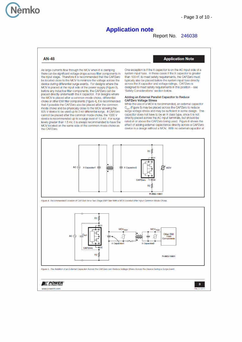
- Page 3 of 10 -
Application noteReport No. 246038

- Page 4 of 10 -
Application noteReport No. 246038

- Page 5 of 10 -
Application noteReport No. 246038

- Page 6 of 10 -
Application noteReport No. 246038

- Page 7 of 10 -
Application noteReport No. 246038

- Page 8 of 10 -
Application noteReport No. 246038

- Page 9 of 10 -
Application noteReport No. 246038

- Page 10 of 10 -
Application noteReport No. 246038